EP3378111B1 - Gamme de batterie - Google Patents
Gamme de batterie Download PDFInfo
- Publication number
- EP3378111B1 EP3378111B1 EP17752281.0A EP17752281A EP3378111B1 EP 3378111 B1 EP3378111 B1 EP 3378111B1 EP 17752281 A EP17752281 A EP 17752281A EP 3378111 B1 EP3378111 B1 EP 3378111B1
- Authority
- EP
- European Patent Office
- Prior art keywords
- battery
- cell
- battery cells
- arrangement according
- recesses
- Prior art date
- Legal status (The legal status is an assumption and is not a legal conclusion. Google has not performed a legal analysis and makes no representation as to the accuracy of the status listed.)
- Active
Links
Images


Classifications
-
- H—ELECTRICITY
- H01—ELECTRIC ELEMENTS
- H01M—PROCESSES OR MEANS, e.g. BATTERIES, FOR THE DIRECT CONVERSION OF CHEMICAL ENERGY INTO ELECTRICAL ENERGY
- H01M6/00—Primary cells; Manufacture thereof
- H01M6/42—Grouping of primary cells into batteries
- H01M6/44—Grouping of primary cells into batteries of tubular or cup-shaped cells
-
- H—ELECTRICITY
- H01—ELECTRIC ELEMENTS
- H01M—PROCESSES OR MEANS, e.g. BATTERIES, FOR THE DIRECT CONVERSION OF CHEMICAL ENERGY INTO ELECTRICAL ENERGY
- H01M50/00—Constructional details or processes of manufacture of the non-active parts of electrochemical cells other than fuel cells, e.g. hybrid cells
- H01M50/20—Mountings; Secondary casings or frames; Racks, modules or packs; Suspension devices; Shock absorbers; Transport or carrying devices; Holders
- H01M50/218—Mountings; Secondary casings or frames; Racks, modules or packs; Suspension devices; Shock absorbers; Transport or carrying devices; Holders characterised by the material
- H01M50/22—Mountings; Secondary casings or frames; Racks, modules or packs; Suspension devices; Shock absorbers; Transport or carrying devices; Holders characterised by the material of the casings or racks
- H01M50/227—Organic material
-
- H—ELECTRICITY
- H01—ELECTRIC ELEMENTS
- H01M—PROCESSES OR MEANS, e.g. BATTERIES, FOR THE DIRECT CONVERSION OF CHEMICAL ENERGY INTO ELECTRICAL ENERGY
- H01M50/00—Constructional details or processes of manufacture of the non-active parts of electrochemical cells other than fuel cells, e.g. hybrid cells
- H01M50/20—Mountings; Secondary casings or frames; Racks, modules or packs; Suspension devices; Shock absorbers; Transport or carrying devices; Holders
- H01M50/204—Racks, modules or packs for multiple batteries or multiple cells
- H01M50/207—Racks, modules or packs for multiple batteries or multiple cells characterised by their shape
- H01M50/213—Racks, modules or packs for multiple batteries or multiple cells characterised by their shape adapted for cells having curved cross-section, e.g. round or elliptic
-
- H—ELECTRICITY
- H01—ELECTRIC ELEMENTS
- H01M—PROCESSES OR MEANS, e.g. BATTERIES, FOR THE DIRECT CONVERSION OF CHEMICAL ENERGY INTO ELECTRICAL ENERGY
- H01M50/00—Constructional details or processes of manufacture of the non-active parts of electrochemical cells other than fuel cells, e.g. hybrid cells
- H01M50/20—Mountings; Secondary casings or frames; Racks, modules or packs; Suspension devices; Shock absorbers; Transport or carrying devices; Holders
- H01M50/218—Mountings; Secondary casings or frames; Racks, modules or packs; Suspension devices; Shock absorbers; Transport or carrying devices; Holders characterised by the material
- H01M50/22—Mountings; Secondary casings or frames; Racks, modules or packs; Suspension devices; Shock absorbers; Transport or carrying devices; Holders characterised by the material of the casings or racks
- H01M50/222—Inorganic material
- H01M50/224—Metals
Definitions
- the invention relates to a battery arrangement with a holding module with similar recesses formed therein for receiving electrical battery cells, part of each battery cell being a cylindrical cell base body, which has a positive contact with a bare metal outer surface in the region of its one end face and with in the region of its other end face a negative contact is provided with a bright metallic outer surface, and with means for cooling and / or heating the holding module.
- Such a battery arrangement which is particularly suitable for accumulators for electric travel drives, is known from US Pat WO 2008/156737 A1 known.
- a battery arrangement is required to have a high electrical output, which leads to a corresponding heating of the individual battery cells. Cooling is therefore required, for which purpose cooling tubes through which cooling fluid flows are passed between adjacent battery rows. In the immediate area of the battery cells, the cooling tubes are deformed so that there is an enlarged contact surface between the flat side of the flat cooling tube and the cylindrical jacket of the respective battery cell.
- a battery cooling system is known, according to which a cooling device is connected in terms of flow via a connecting line to the interior of an airtight housing.
- Several battery cells are hermetically sealed in the housing.
- the individual battery cells are cylindrical with a circular cross section. Accordingly, there is a space between the batteries through which liquid coolant can flow.
- the known battery cooling system is insufficient in terms of cooling capacity.
- the housing is not suitable for dissipating even one cell's heat as quickly as possible in the event of an explosion.
- the mechanical protection is insufficient.
- the invention is based on the object of designing and developing a battery arrangement of the generic type in such a way that mechanical protection is ensured in the event of an explosion of one or more battery cells with a sufficiently good cooling capacity.
- the holding module be a homogeneous body made of heat-conducting material, such as, for example, which can be flowed through by a heat transfer fluid.
- Such a holding module enables a high cooling capacity on the lateral surfaces of the battery cells.
- the holding module being a homogeneous, ie one-piece body made of a good heat-conducting material such as B. is aluminum, which is also flowed through by a cooling fluid and is provided with cooling channels in its interior.
- Recesses for receiving the electrical battery cells extend between a first outside and a second outside of the homogeneous body parallel to this. Each recess extends continuously and without changing its cross-section between the outer sides. Each recess is therefore only open to the outside and not in other directions.
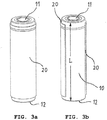
- each cell base body is covered over its circumference and most of its length by a good heat-conducting jacket of its own. B. enclosed in silicone. With this jacket, the cell base body lies flat against the cylindrical wall sections.
- starting product z. B. can be an aluminum block on which the recesses can be made by drilling or milling processes only. Also a complete production from cast metal, as an extruded module or in an additive process, i.e. in a 3-D printing process is possible.
- the individual battery cells are inserted into the so manufactured or during casting the same with shaped recesses in the longitudinal direction of the battery, which allows an overall simple and, above all, fully automated assembly, in which, for. B. a plurality of battery cells can be used simultaneously in the homogeneous aluminum body.
- this jacket made of a good heat-conducting material with which each cell base of the battery cells is enclosed.
- this jacket can, for. B. consist of silicone, but can achieve good heat transfer values and thus good heat dissipation from the battery cells even with a jacket made of polyethylene, polypropylene or rubber.
- the cylindrical wall sections of the recesses in the longitudinal direction of the battery are each shorter than the basic cell body of the battery cell. Accordingly, the distance between the two outer sides of the holding module is also less than the length of the basic cell body.
- each recess accommodates only a single battery cell.
- the cross section of the recess can be circular-cylindrical, as a result of which heat transfer is possible over the entire circumference of the battery cell.
- a variant can be more favorable in which the recesses are enlarged by having an elongated cross section and each accommodating a group of battery cells.
- the battery cells forming this group are preferably arranged in a straight row.
- the elongated cross section of such an enlarged recess is composed of cross-sectional areas formed by the cylindrical wall sections, in which the battery cells are located, and transition areas, wherein the width of the recess in the transition areas is smaller than in the cross-sectional areas.
- the battery cells are preferably arranged in rows of cells.
- the battery cells are preferably arranged in a plurality of cell rows which are parallel to one another, the battery cells in mutually adjacent cell rows being mutually offset.
- the cell row adjacent to this cell row also consists of battery cells with uniform polarity, although the polarity of the battery cells combined therein is opposite in directly adjacent cell rows.
- a construction is advantageous in which a plurality of battery cells are electrically connected in series and the series extends at right angles to the elongated cross section of the recesses.
- a further embodiment is characterized by an arrangement of the battery cells in at least two battery groups, the battery groups being separated from one another by the cooling channel formed in the holding module and through which a cooling fluid can flow.
- the cooling channel preferably extends transversely to the direction of the cell rows.
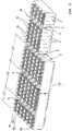
- the battery arrangement according to the Figures 1 and 2nd finds application z. B. as an accumulator of a vehicle with a powerful electric travel drive. However, other areas of application are also possible in which a high battery or battery power is required.
- rechargeable batteries also known as rechargeable batteries.
- the basic component of the battery arrangement is an overall block-shaped holding module 2.
- the holding module 2 is a homogeneous, one-piece body made of a metal, which can be electrically conductive, and which is characterized above all by good heat conduction.
- Particularly suitable as a holding module is e.g. B. an aluminum block.
- In the block there are cooling channels 9, through which a heat transfer fluid can flow, in order to either cool the block or, in the case of low outside temperatures, to heat the block and thus bring the batteries to working temperature.
- the heat transfer fluid can, for. B. be water, or a suitable oil.
- the holding module 2 is provided with a plurality of similar recesses 4 for the purpose of equipping it with electrical battery cells 5.
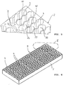
- the recesses 4, whose shape mainly from the Figures 4 - 7 can be easily recognized, are introduced into the metal block by drilling or milling processes, for example.
- the cooling channels 9 can also be produced using the same technology.
- the holding module 2 is designed here as a rectangular cuboid, the length of which is greater than its width, but other geometries are also possible, depending on the purpose and location.
- height H of the holding module 2 is less than its length and width.
- the height H also designates the distance between a first outer side 7A and a second outer side 7B of the holding module 2 parallel to this.
- the longitudinal axes of the cylindrical battery cells 5 extend perpendicular to the two outer sides 7A, 7B.
- the recesses 4 extend continuously and without changing their cross-section between the two outer sides 7A, 7B of the homogeneous body. Each 5 recess 4 is only open to these outer sides 7A, 7B, and not z. B. across.
- the cross section of the recesses 4 is designed such that at least wall sections 22, 23 of the recesses are partially cylindrical, and a cylindrical battery cell 5 is arranged in this partially cylindrical cross section.
- a battery cell 5 is shown in dashed lines in one of the recesses 4. It can be seen that the cylindrical wall sections 22, 23 extend over a large part of the circumference of the battery cell 5, and on the wall sections 22, 23 there is direct, flat contact and thus an area of intensive heat transfer between the battery cell 5 and the wall of the recess 4 consists.
- this protective sheath can first be removed and removed by the sheath 20 from e.g. B. silicone can be replaced.
- the jacket 20 should cover at least 75% of the length L of the cell base body 10.
- the rather centrally arranged recesses in the holding module 2 are of such a length that these recesses accommodate a larger number of battery cells 5, in the exemplary embodiment six battery cells.
- the recesses 4 arranged on the longitudinal ends of the module 2 are of such a length that these recesses accommodate only a smaller number and preferably only half of the battery cells 5, ie three battery cells in the exemplary embodiment.
- each recess 4 can accommodate more than just one battery cell
- the cross section of the recess 4 is composed of cross-sectional sections 25 formed by the cylindrical wall sections 22, 23, in which the battery cells are located, and transition regions 26 arranged therebetween, the width B being the Recess 4 in the transition regions 26 is smaller than in the cross-sectional regions 25.
- each recess 4 receives a group of battery cells 5, the battery cells 5 of the group forming a row.
- each recess 4 it is also possible to arrange a separate, cylindrical recess in the holding module for each individual battery cell 5.
- the excess heat from the battery cell is dissipated as best as possible to the fully enclosing metal of the holding module.
- this heat is transferred well to the battery cell 5 in order to bring it to the optimum operating temperature for the battery cell, for example at low initial temperatures.
- the fluid channels 9, which serve as cooling channels or as heating channels depending on the operating situation, run transversely to the longitudinal extent of the recesses 4, and thus also transversely to the cell rows R1, R2, R3 in which the battery cells 5 are arranged.
- the battery cells 5 in immediately adjacent cell rows R1 and R2 or R2 and R3 are mutually offset in the holding module 2.
- the walls 40 between adjacent recesses 4 thus have an undulating course. This arrangement of the recesses enables a high packing density of the battery cells and thus also a particularly compact holding module 2.
- All battery cells 5, which are arranged in a common recess 4, have the same polarity, that is, the same orientation of their electrical contacts 11, 12.
- all battery cells of a cell row R1, R2, R3 have the same polarity.
- the polarity of the battery cells combined therein is opposite in the respectively immediately adjacent cell row.
- cell rows whose batteries have a first polarity alternate with cell rows whose batteries have the reverse polarity. This clearly shows the Fig. 1 recognize, in which the plus contacts 11 and the minus contacts 12 of individual battery cells 5 are designated.
- the battery arrangement has a common positive conductor 34 along one long side of the holding module 2 and a common negative conductor 35 along the other long side.
- An electrical connection 32 leads from the positive conductor 34 to the positive contact 11 of the battery cell in the cell row immediately adjacent to the positive conductor 34.
- a connection 33 leads from the common negative conductor 35 to the negative contact 12 of the battery cell in the cell row immediately adjacent to the negative conductor 35.
- Contact elements 39 each bridge the positive contact 11 of the battery cell of one cell row with the negative contact 12 of the battery cell of the adjacent cell row.
- This electrical series connection extends transversely to the recesses 4 and to the cell rows R1, R2, R3. With this type of electrical contacting, a plurality of battery cells are therefore electrically connected in series, and this series extends at right angles to the extension of the elongate cross section of the recesses 4.
Landscapes
- Chemical & Material Sciences (AREA)
- Chemical Kinetics & Catalysis (AREA)
- Electrochemistry (AREA)
- General Chemical & Material Sciences (AREA)
- Inorganic Chemistry (AREA)
- Engineering & Computer Science (AREA)
- Manufacturing & Machinery (AREA)
- Secondary Cells (AREA)
- Battery Mounting, Suspending (AREA)
Claims (15)
- Gamme de batterie, avec un module de retenue (2) avec des creux (4) similaires qui y sont constitués intérieurement et qui sont destinés à recevoir des éléments de batterie (5) électriques, un corps de base d'élément (10) cylindrique faisant partie intégrante de chaque élément de batterie (5) et étant, dans la zone d'un côté frontal, muni d'un contact positif (11) avec une surface extérieure métallique nue et, dans la zone de son autre côté frontal, muni d'un contact négatif (12) avec une surface extérieure métallique nue, et avec des moyens pour refroidir et/ou chauffer le module de retenue (2),
caractérisée en ce que le module de retenue (2) est un corps homogène, pouvant être parcouru par un fluide caloporteur, en matériau conducteur de la chaleur comme par exemple de l'aluminium, avec un premier côté extérieur (7A) et un deuxième côté extérieur (7B) parallèle à celui-ci, en ce que les creux (4) s'étendent respectivement entre les côtés extérieurs (7A, 7B) de façon continue et sans variation de leur section transversale et ne sont ouverts qu'au niveau des côtés extérieurs (7A, 7B), en ce qu'au moins des tronçons de paroi (22, 23) des creux (4) sont cylindriques, et en ce que chaque corps de base d'élément (10) est, sur sa périphérie et sur la majeure partie de sa longueur, entouré d'une propre enveloppe (20) conduisant la chaleur et est, par cette enveloppe, adjacent sur toute sa surface aux tronçons de paroi (22, 23). - Gamme de batterie selon la revendication 1, caractérisée en ce que l'enveloppe (20) se compose de l'un des matériaux parmi le silicone, le polyéthylène, le polypropylène ou le caoutchouc.
- Gamme de batterie selon la revendication 1 ou 2, caractérisée en ce que l'enveloppe (20) présente la forme d'un manchon ouvert aux deux extrémités.
- Gamme de batterie selon l'une des revendications 1 à 3, caractérisée en ce que l'enveloppe (20) couvre au moins 75 % de la longueur (L) du corps de base d'élément (10).
- Gamme de batterie selon l'une des revendications 1 à 4, caractérisée en ce que, dans la direction longitudinale de batterie, les tronçons de paroi (22, 23) sont respectivement plus courts que le corps de base d'élément (10).
- Gamme de batterie selon l'une des revendications 1 à 5, caractérisée en ce que, pour chaque élément de batterie (5), le contact positif (11) de celui-ci dépasse de l'un des côtés extérieurs (7A, 7B), et le contact négatif (12) dépasse de l'autre des côtés extérieurs (7A, 7B) du module de retenue (2).
- Gamme de batterie selon l'une des revendications 1 à 6, caractérisée en ce que les creux reçoivent respectivement un élément de batterie (5) individuel, la section transversale du creux pouvant avoir la forme d'un cylindre circulaire.
- Gamme de batterie selon l'une des revendications 1 à 7, caractérisée en ce que les creux (4) comportent une section transversale de forme allongée et reçoivent respectivement un groupe d'éléments de batterie (5).
- Gamme de batterie selon la revendication 8, caractérisé en ce que les éléments de batterie (5) formant le groupe sont disposés en une rangée, et en ce que la section transversale du creux (4) se compose de zones de section transversale (25), formées par les tronçons de paroi (22, 23) cylindriques, dans lesquelles se trouvent les éléments de batterie (5), et de zones de transition (26), la largeur (B) du creux (4) étant plus faible dans les zones de transition (26) que dans les zones de section transversale (25).
- Gamme de batterie selon l'une des revendications 1 à 9, caractérisée en ce que les éléments de batterie (5) sont disposés en rangées d'éléments (R1, R2, R3, ...), les éléments de batterie (5) pouvant être disposés en plusieurs rangées d'éléments (R1, R2, R3, ...) parallèles entre elles, et les éléments de batterie (5) pouvant, dans le module de retenue (2), être disposés en rangées d'éléments directement voisines alternativement de façon décalée les uns par rapport aux autres.
- Gamme de batterie selon la revendication 10, caractérisée en ce que tous les éléments de batterie (5) d'une rangée d'éléments présentent la même polarité, la rangée d'éléments voisine de la rangée d'éléments pouvant également se composer d'éléments de batterie (5) de polarité uniforme.
- Gamme de batterie selon les revendications 10 à 11, caractérisée en ce que, dans des rangées d'éléments directement voisines, la polarité des éléments de batterie (5) qui y sont rassemblés intérieurement est opposée.
- Gamme de batterie selon l'une des revendications 10 à 12, caractérisée en ce qu'une pluralité d'éléments de batterie (5) sont montés électriquement en série et en ce que la rangée s'étend à angle droit par rapport à la section transversale de forme allongée des creux (4).
- Gamme de batterie selon l'une des revendications 1 à 13, caractérisée par un agencement des éléments de batterie (5) en au moins deux groupes de batteries (G1, G2, G3), les groupes de batteries étant séparés les uns des autres par un canal de refroidissement (9) qui est constitué dans le module de retenue (2) et qui peut être parcouru par un fluide de refroidissement.
- Gamme de batterie selon l'une des revendications 10 à 14, caractérisée en ce que le canal de refroidissement (9) s'étend transversalement aux rangées d'éléments (R1, R2, R3).
Applications Claiming Priority (2)
| Application Number | Priority Date | Filing Date | Title |
|---|---|---|---|
| DE102016113177.6A DE102016113177A1 (de) | 2016-07-18 | 2016-07-18 | Batterieanordnung |
| PCT/DE2017/200063 WO2018014918A1 (fr) | 2016-07-18 | 2017-07-06 | Agencement de batterie |
Publications (2)
| Publication Number | Publication Date |
|---|---|
| EP3378111A1 EP3378111A1 (fr) | 2018-09-26 |
| EP3378111B1 true EP3378111B1 (fr) | 2020-05-13 |
Family
ID=59631506
Family Applications (1)
| Application Number | Title | Priority Date | Filing Date |
|---|---|---|---|
| EP17752281.0A Active EP3378111B1 (fr) | 2016-07-18 | 2017-07-06 | Gamme de batterie |
Country Status (5)
| Country | Link |
|---|---|
| EP (1) | EP3378111B1 (fr) |
| CN (1) | CN109716552B (fr) |
| DE (1) | DE102016113177A1 (fr) |
| ES (1) | ES2805099T3 (fr) |
| WO (1) | WO2018014918A1 (fr) |
Families Citing this family (11)
| Publication number | Priority date | Publication date | Assignee | Title |
|---|---|---|---|---|
| WO2020200338A1 (fr) * | 2019-04-05 | 2020-10-08 | Scio Technology Gmbh | Boîtier de macro-module d'éléments de batterie, dispositif de mise en contact pour un boîtier de macro-module d'éléments de batterie, couvercle de boîtier pour un dispositif de mise en contact pour un boîtier de macro-module d'éléments de batterie et un macro-module d'éléments de batterie |
| CN114641892A (zh) * | 2019-12-27 | 2022-06-17 | 松下知识产权经营株式会社 | 蓄电模块 |
| CN111477994B (zh) * | 2020-06-28 | 2020-11-13 | 四川大学 | 具有分流结构的一体式动力电池组冷却系统及电池组 |
| CN111540866B (zh) * | 2020-07-08 | 2020-10-09 | 深圳小木科技有限公司 | 一种电池组与新能源汽车 |
| DE102020120992A1 (de) * | 2020-08-10 | 2022-02-10 | Volkswagen Aktiengesellschaft | Batterieanordnung |
| DE102021121980A1 (de) * | 2021-08-25 | 2023-03-02 | Schuler Pressen Gmbh | Batterie |
| ES1284470Y (es) * | 2021-12-10 | 2022-03-21 | Stark Future S L | Carcasa para bateria electrica |
| WO2023105110A1 (fr) * | 2021-12-10 | 2023-06-15 | Stark Future, S.L. | Carcasse pour pile électrique |
| ES1284379Y (es) * | 2021-12-10 | 2022-03-16 | Stark Future S L | Carcasa para bateria electrica |
| AT527068B1 (de) * | 2023-03-16 | 2025-01-15 | John Deere Electric Powertrain Llc | Temperiervorrichtung für ein Batteriesystem mit einem Grundkörper und mehreren, in einem Strömungskanal angeordneten Lagerhülsen |
| DE102023130442A1 (de) * | 2023-11-03 | 2025-05-08 | Bayerische Motoren Werke Aktiengesellschaft | Batteriemodul für eine Batterie, insbesondere eine Traktionsbatterie eines Kraftfahrzeugs, Kraftfahrzeug, Verfahren und Baukastensystem |
Family Cites Families (9)
| Publication number | Priority date | Publication date | Assignee | Title |
|---|---|---|---|---|
| JP4123541B2 (ja) * | 1997-07-02 | 2008-07-23 | 株式会社デンソー | 電池冷却装置 |
| DE10352046A1 (de) * | 2003-11-07 | 2005-06-09 | Daimlerchrysler Ag | Batterie mit wenigstens einer elektrochemischen Speicherzelle und einer Kühleinrichtung |
| AT9922U1 (de) * | 2006-09-18 | 2008-05-15 | Magna Steyr Fahrzeugtechnik Ag | Hochtemperaturbatterie mit gekühlter trägerplatte |
| US20080311468A1 (en) | 2007-06-18 | 2008-12-18 | Weston Arthur Hermann | Optimized cooling tube geometry for intimate thermal contact with cells |
| DE102008034874B4 (de) * | 2008-07-26 | 2011-06-30 | Daimler AG, 70327 | Batterie und Verwendung einer Batterie |
| DE102008054947A1 (de) * | 2008-12-19 | 2010-06-24 | Robert Bosch Gmbh | Wiederaufladbare Batterie mit einer Wärmetransporteinrichtung zum Heizen und/oder Kühlen der Batterie |
| DE102010005097A1 (de) * | 2010-01-20 | 2011-07-21 | Fraunhofer-Gesellschaft zur Förderung der angewandten Forschung e.V., 80686 | Temperierbare Batteriezellenanordnung |
| US10312554B2 (en) * | 2014-01-28 | 2019-06-04 | Ford Global Technologies, Llc | Battery cooling channel with integrated cell retention features |
| CN105552472A (zh) * | 2016-01-26 | 2016-05-04 | 苏州安靠电源有限公司 | 大容量电池组温控装置和具有该装置的大容量电池组 |
-
2016
- 2016-07-18 DE DE102016113177.6A patent/DE102016113177A1/de not_active Ceased
-
2017
- 2017-07-06 WO PCT/DE2017/200063 patent/WO2018014918A1/fr not_active Ceased
- 2017-07-06 ES ES17752281T patent/ES2805099T3/es active Active
- 2017-07-06 EP EP17752281.0A patent/EP3378111B1/fr active Active
- 2017-07-06 CN CN201780057080.6A patent/CN109716552B/zh active Active
Non-Patent Citations (1)
| Title |
|---|
| None * |
Also Published As
| Publication number | Publication date |
|---|---|
| DE102016113177A1 (de) | 2018-01-18 |
| CN109716552A (zh) | 2019-05-03 |
| WO2018014918A1 (fr) | 2018-01-25 |
| ES2805099T3 (es) | 2021-02-10 |
| EP3378111A1 (fr) | 2018-09-26 |
| CN109716552B (zh) | 2022-04-29 |
Similar Documents
| Publication | Publication Date | Title |
|---|---|---|
| EP3378111B1 (fr) | Gamme de batterie | |
| DE102007063190B4 (de) | Batterie, bestehend aus mehreren Einzelzellen, insbesondere für einen Hybridantrieb | |
| DE102008034699B4 (de) | Batterie mit mehreren Batteriezellen | |
| EP2497145B1 (fr) | Dispositif accumulateur d'énergie | |
| DE102012012294B4 (de) | Fahrzeug mit einer Batterieanordnung | |
| EP3472877B1 (fr) | Module accumulateur à conduction du courant optimisée | |
| DE102007010744B4 (de) | Batteriezelle einer Batterie, Zellverbund aus Batteriezellen und Verwendung mehrerer Zellen | |
| EP2291874A1 (fr) | Accumulateur à piles rondes | |
| DE202007017390U1 (de) | Wärmeaustauscher-Vorrichtung für einen elektrochemischen Energiespeicher | |
| DE102011084536B4 (de) | Kühleinrichtung für einen elektrischen Energiespeicher und Energiespeichervorrichtung | |
| EP2210296A1 (fr) | Batterie d'accumulateurs cylindriques | |
| DE102009035488A1 (de) | Batterie, insbesondere Fahrzeugbatterie | |
| DE102008034875A1 (de) | Batterie, insbesondere Fahrzeugbatterie | |
| DE102011109246A1 (de) | HV-Batterie für alternative Antriebe | |
| WO2017167563A1 (fr) | Dispositif d'équilibrage de température d'un module de batterie, son procédé de fabrication et module de batterie | |
| EP3729538A1 (fr) | Bloc-batterie pour machine-outil portative | |
| DE102012205750B4 (de) | Kühlmittelverteiler für eine Mehrzahl von Kühleinrichtungen, Kühlsystem und Energiespeicher mit einem Kühlsystem | |
| DE102022134765A1 (de) | Gegenstromtemperierungsvorrichtung, Batteriegehäuse zur Verwendung einer Temperierungsvorrichtung | |
| DE102020121370A1 (de) | Sekundärbatterie und batteriemodul mit einer solchen batterie | |
| EP2697843B1 (fr) | Ensemble accumulateur pourvu d'un dispositif de refroidissement | |
| DE102016222630A1 (de) | Kühlvorrichtung und Verfahren zum Herstellen einer Kühlvorrichtung | |
| EP3014207B1 (fr) | Échangeur de chaleur | |
| DE102018114023B4 (de) | Kühlgehäuse für eine Batterie und ein dieses enthaltendes Batteriemodul | |
| DE102017128878A1 (de) | Batteriemodul und Modulgehäuse | |
| DE102022112213B4 (de) | Trägervorrichtung für Batterierundzellen eines Fahrzeugs |
Legal Events
| Date | Code | Title | Description |
|---|---|---|---|
| STAA | Information on the status of an ep patent application or granted ep patent |
Free format text: STATUS: UNKNOWN |
|
| STAA | Information on the status of an ep patent application or granted ep patent |
Free format text: STATUS: THE INTERNATIONAL PUBLICATION HAS BEEN MADE |
|
| PUAI | Public reference made under article 153(3) epc to a published international application that has entered the european phase |
Free format text: ORIGINAL CODE: 0009012 |
|
| STAA | Information on the status of an ep patent application or granted ep patent |
Free format text: STATUS: REQUEST FOR EXAMINATION WAS MADE |
|
| 17P | Request for examination filed |
Effective date: 20180618 |
|
| AK | Designated contracting states |
Kind code of ref document: A1 Designated state(s): AL AT BE BG CH CY CZ DE DK EE ES FI FR GB GR HR HU IE IS IT LI LT LU LV MC MK MT NL NO PL PT RO RS SE SI SK SM TR |
|
| AX | Request for extension of the european patent |
Extension state: BA ME |
|
| DAV | Request for validation of the european patent (deleted) | ||
| DAX | Request for extension of the european patent (deleted) | ||
| GRAP | Despatch of communication of intention to grant a patent |
Free format text: ORIGINAL CODE: EPIDOSNIGR1 |
|
| STAA | Information on the status of an ep patent application or granted ep patent |
Free format text: STATUS: GRANT OF PATENT IS INTENDED |
|
| INTG | Intention to grant announced |
Effective date: 20191217 |
|
| GRAS | Grant fee paid |
Free format text: ORIGINAL CODE: EPIDOSNIGR3 |
|
| GRAA | (expected) grant |
Free format text: ORIGINAL CODE: 0009210 |
|
| STAA | Information on the status of an ep patent application or granted ep patent |
Free format text: STATUS: THE PATENT HAS BEEN GRANTED |
|
| AK | Designated contracting states |
Kind code of ref document: B1 Designated state(s): AL AT BE BG CH CY CZ DE DK EE ES FI FR GB GR HR HU IE IS IT LI LT LU LV MC MK MT NL NO PL PT RO RS SE SI SK SM TR |
|
| REG | Reference to a national code |
Ref country code: GB Ref legal event code: FG4D Free format text: NOT ENGLISH |
|
| REG | Reference to a national code |
Ref country code: CH Ref legal event code: EP |
|
| REG | Reference to a national code |
Ref country code: DE Ref legal event code: R096 Ref document number: 502017005314 Country of ref document: DE |
|
| REG | Reference to a national code |
Ref country code: AT Ref legal event code: REF Ref document number: 1271398 Country of ref document: AT Kind code of ref document: T Effective date: 20200615 |
|
| REG | Reference to a national code |
Ref country code: LT Ref legal event code: MG4D |
|
| REG | Reference to a national code |
Ref country code: NL Ref legal event code: MP Effective date: 20200513 |
|
| PG25 | Lapsed in a contracting state [announced via postgrant information from national office to epo] |
Ref country code: IS Free format text: LAPSE BECAUSE OF FAILURE TO SUBMIT A TRANSLATION OF THE DESCRIPTION OR TO PAY THE FEE WITHIN THE PRESCRIBED TIME-LIMIT Effective date: 20200913 Ref country code: PT Free format text: LAPSE BECAUSE OF FAILURE TO SUBMIT A TRANSLATION OF THE DESCRIPTION OR TO PAY THE FEE WITHIN THE PRESCRIBED TIME-LIMIT Effective date: 20200914 Ref country code: GR Free format text: LAPSE BECAUSE OF FAILURE TO SUBMIT A TRANSLATION OF THE DESCRIPTION OR TO PAY THE FEE WITHIN THE PRESCRIBED TIME-LIMIT Effective date: 20200814 Ref country code: NO Free format text: LAPSE BECAUSE OF FAILURE TO SUBMIT A TRANSLATION OF THE DESCRIPTION OR TO PAY THE FEE WITHIN THE PRESCRIBED TIME-LIMIT Effective date: 20200813 Ref country code: SE Free format text: LAPSE BECAUSE OF FAILURE TO SUBMIT A TRANSLATION OF THE DESCRIPTION OR TO PAY THE FEE WITHIN THE PRESCRIBED TIME-LIMIT Effective date: 20200513 Ref country code: LT Free format text: LAPSE BECAUSE OF FAILURE TO SUBMIT A TRANSLATION OF THE DESCRIPTION OR TO PAY THE FEE WITHIN THE PRESCRIBED TIME-LIMIT Effective date: 20200513 Ref country code: FI Free format text: LAPSE BECAUSE OF FAILURE TO SUBMIT A TRANSLATION OF THE DESCRIPTION OR TO PAY THE FEE WITHIN THE PRESCRIBED TIME-LIMIT Effective date: 20200513 |
|
| REG | Reference to a national code |
Ref country code: DE Ref legal event code: R079 Ref document number: 502017005314 Country of ref document: DE Free format text: PREVIOUS MAIN CLASS: H01M0002100000 Ipc: H01M0050200000 |
|
| PG25 | Lapsed in a contracting state [announced via postgrant information from national office to epo] |
Ref country code: BG Free format text: LAPSE BECAUSE OF FAILURE TO SUBMIT A TRANSLATION OF THE DESCRIPTION OR TO PAY THE FEE WITHIN THE PRESCRIBED TIME-LIMIT Effective date: 20200813 Ref country code: HR Free format text: LAPSE BECAUSE OF FAILURE TO SUBMIT A TRANSLATION OF THE DESCRIPTION OR TO PAY THE FEE WITHIN THE PRESCRIBED TIME-LIMIT Effective date: 20200513 Ref country code: LV Free format text: LAPSE BECAUSE OF FAILURE TO SUBMIT A TRANSLATION OF THE DESCRIPTION OR TO PAY THE FEE WITHIN THE PRESCRIBED TIME-LIMIT Effective date: 20200513 Ref country code: RS Free format text: LAPSE BECAUSE OF FAILURE TO SUBMIT A TRANSLATION OF THE DESCRIPTION OR TO PAY THE FEE WITHIN THE PRESCRIBED TIME-LIMIT Effective date: 20200513 |
|
| PG25 | Lapsed in a contracting state [announced via postgrant information from national office to epo] |
Ref country code: AL Free format text: LAPSE BECAUSE OF FAILURE TO SUBMIT A TRANSLATION OF THE DESCRIPTION OR TO PAY THE FEE WITHIN THE PRESCRIBED TIME-LIMIT Effective date: 20200513 Ref country code: NL Free format text: LAPSE BECAUSE OF FAILURE TO SUBMIT A TRANSLATION OF THE DESCRIPTION OR TO PAY THE FEE WITHIN THE PRESCRIBED TIME-LIMIT Effective date: 20200513 |
|
| PG25 | Lapsed in a contracting state [announced via postgrant information from national office to epo] |
Ref country code: DK Free format text: LAPSE BECAUSE OF FAILURE TO SUBMIT A TRANSLATION OF THE DESCRIPTION OR TO PAY THE FEE WITHIN THE PRESCRIBED TIME-LIMIT Effective date: 20200513 Ref country code: CZ Free format text: LAPSE BECAUSE OF FAILURE TO SUBMIT A TRANSLATION OF THE DESCRIPTION OR TO PAY THE FEE WITHIN THE PRESCRIBED TIME-LIMIT Effective date: 20200513 Ref country code: RO Free format text: LAPSE BECAUSE OF FAILURE TO SUBMIT A TRANSLATION OF THE DESCRIPTION OR TO PAY THE FEE WITHIN THE PRESCRIBED TIME-LIMIT Effective date: 20200513 Ref country code: EE Free format text: LAPSE BECAUSE OF FAILURE TO SUBMIT A TRANSLATION OF THE DESCRIPTION OR TO PAY THE FEE WITHIN THE PRESCRIBED TIME-LIMIT Effective date: 20200513 Ref country code: SM Free format text: LAPSE BECAUSE OF FAILURE TO SUBMIT A TRANSLATION OF THE DESCRIPTION OR TO PAY THE FEE WITHIN THE PRESCRIBED TIME-LIMIT Effective date: 20200513 |
|
| REG | Reference to a national code |
Ref country code: ES Ref legal event code: FG2A Ref document number: 2805099 Country of ref document: ES Kind code of ref document: T3 Effective date: 20210210 |
|
| REG | Reference to a national code |
Ref country code: DE Ref legal event code: R097 Ref document number: 502017005314 Country of ref document: DE |
|
| PG25 | Lapsed in a contracting state [announced via postgrant information from national office to epo] |
Ref country code: PL Free format text: LAPSE BECAUSE OF FAILURE TO SUBMIT A TRANSLATION OF THE DESCRIPTION OR TO PAY THE FEE WITHIN THE PRESCRIBED TIME-LIMIT Effective date: 20200513 Ref country code: MC Free format text: LAPSE BECAUSE OF FAILURE TO SUBMIT A TRANSLATION OF THE DESCRIPTION OR TO PAY THE FEE WITHIN THE PRESCRIBED TIME-LIMIT Effective date: 20200513 Ref country code: SK Free format text: LAPSE BECAUSE OF FAILURE TO SUBMIT A TRANSLATION OF THE DESCRIPTION OR TO PAY THE FEE WITHIN THE PRESCRIBED TIME-LIMIT Effective date: 20200513 |
|
| PLBE | No opposition filed within time limit |
Free format text: ORIGINAL CODE: 0009261 |
|
| STAA | Information on the status of an ep patent application or granted ep patent |
Free format text: STATUS: NO OPPOSITION FILED WITHIN TIME LIMIT |
|
| 26N | No opposition filed |
Effective date: 20210216 |
|
| REG | Reference to a national code |
Ref country code: BE Ref legal event code: MM Effective date: 20200731 |
|
| PG25 | Lapsed in a contracting state [announced via postgrant information from national office to epo] |
Ref country code: LU Free format text: LAPSE BECAUSE OF NON-PAYMENT OF DUE FEES Effective date: 20200706 Ref country code: IE Free format text: LAPSE BECAUSE OF NON-PAYMENT OF DUE FEES Effective date: 20200706 |
|
| PG25 | Lapsed in a contracting state [announced via postgrant information from national office to epo] |
Ref country code: BE Free format text: LAPSE BECAUSE OF NON-PAYMENT OF DUE FEES Effective date: 20200731 Ref country code: SI Free format text: LAPSE BECAUSE OF FAILURE TO SUBMIT A TRANSLATION OF THE DESCRIPTION OR TO PAY THE FEE WITHIN THE PRESCRIBED TIME-LIMIT Effective date: 20200513 |
|
| GBPC | Gb: european patent ceased through non-payment of renewal fee |
Effective date: 20210706 |
|
| PG25 | Lapsed in a contracting state [announced via postgrant information from national office to epo] |
Ref country code: GB Free format text: LAPSE BECAUSE OF NON-PAYMENT OF DUE FEES Effective date: 20210706 |
|
| PG25 | Lapsed in a contracting state [announced via postgrant information from national office to epo] |
Ref country code: MT Free format text: LAPSE BECAUSE OF FAILURE TO SUBMIT A TRANSLATION OF THE DESCRIPTION OR TO PAY THE FEE WITHIN THE PRESCRIBED TIME-LIMIT Effective date: 20200513 Ref country code: CY Free format text: LAPSE BECAUSE OF FAILURE TO SUBMIT A TRANSLATION OF THE DESCRIPTION OR TO PAY THE FEE WITHIN THE PRESCRIBED TIME-LIMIT Effective date: 20200513 |
|
| PG25 | Lapsed in a contracting state [announced via postgrant information from national office to epo] |
Ref country code: MK Free format text: LAPSE BECAUSE OF FAILURE TO SUBMIT A TRANSLATION OF THE DESCRIPTION OR TO PAY THE FEE WITHIN THE PRESCRIBED TIME-LIMIT Effective date: 20200513 |
|
| PGFP | Annual fee paid to national office [announced via postgrant information from national office to epo] |
Ref country code: TR Payment date: 20240627 Year of fee payment: 8 |
|
| PGFP | Annual fee paid to national office [announced via postgrant information from national office to epo] |
Ref country code: FR Payment date: 20240724 Year of fee payment: 8 |
|
| PGFP | Annual fee paid to national office [announced via postgrant information from national office to epo] |
Ref country code: ES Payment date: 20240816 Year of fee payment: 8 |
|
| PGFP | Annual fee paid to national office [announced via postgrant information from national office to epo] |
Ref country code: AT Payment date: 20240718 Year of fee payment: 8 |
|
| PGFP | Annual fee paid to national office [announced via postgrant information from national office to epo] |
Ref country code: IT Payment date: 20240731 Year of fee payment: 8 |
|
| PGFP | Annual fee paid to national office [announced via postgrant information from national office to epo] |
Ref country code: DE Payment date: 20250929 Year of fee payment: 9 |
|
| PGFP | Annual fee paid to national office [announced via postgrant information from national office to epo] |
Ref country code: CH Payment date: 20250801 Year of fee payment: 9 |
|
| REG | Reference to a national code |
Ref country code: AT Ref legal event code: MM01 Ref document number: 1271398 Country of ref document: AT Kind code of ref document: T Effective date: 20250706 |
|
| PG25 | Lapsed in a contracting state [announced via postgrant information from national office to epo] |
Ref country code: AT Free format text: LAPSE BECAUSE OF NON-PAYMENT OF DUE FEES Effective date: 20250706 |
|
| PG25 | Lapsed in a contracting state [announced via postgrant information from national office to epo] |
Ref country code: FR Free format text: LAPSE BECAUSE OF NON-PAYMENT OF DUE FEES Effective date: 20250731 |