EP3378113B1 - Blocs-batteries et procédé d'assemblage de blocs-batteries - Google Patents
Blocs-batteries et procédé d'assemblage de blocs-batteries Download PDFInfo
- Publication number
- EP3378113B1 EP3378113B1 EP16891051.1A EP16891051A EP3378113B1 EP 3378113 B1 EP3378113 B1 EP 3378113B1 EP 16891051 A EP16891051 A EP 16891051A EP 3378113 B1 EP3378113 B1 EP 3378113B1
- Authority
- EP
- European Patent Office
- Prior art keywords
- terminals
- connector
- battery pack
- configurable
- battery
- Prior art date
- Legal status (The legal status is an assumption and is not a legal conclusion. Google has not performed a legal analysis and makes no representation as to the accuracy of the status listed.)
- Active
Links
Images








Classifications
-
- H—ELECTRICITY
- H01—ELECTRIC ELEMENTS
- H01M—PROCESSES OR MEANS, e.g. BATTERIES, FOR THE DIRECT CONVERSION OF CHEMICAL ENERGY INTO ELECTRICAL ENERGY
- H01M10/00—Secondary cells; Manufacture thereof
- H01M10/42—Methods or arrangements for servicing or maintenance of secondary cells or secondary half-cells
- H01M10/425—Structural combination with electronic components, e.g. electronic circuits integrated to the outside of the casing
-
- H—ELECTRICITY
- H01—ELECTRIC ELEMENTS
- H01M—PROCESSES OR MEANS, e.g. BATTERIES, FOR THE DIRECT CONVERSION OF CHEMICAL ENERGY INTO ELECTRICAL ENERGY
- H01M50/00—Constructional details or processes of manufacture of the non-active parts of electrochemical cells other than fuel cells, e.g. hybrid cells
- H01M50/20—Mountings; Secondary casings or frames; Racks, modules or packs; Suspension devices; Shock absorbers; Transport or carrying devices; Holders
- H01M50/204—Racks, modules or packs for multiple batteries or multiple cells
- H01M50/207—Racks, modules or packs for multiple batteries or multiple cells characterised by their shape
- H01M50/213—Racks, modules or packs for multiple batteries or multiple cells characterised by their shape adapted for cells having curved cross-section, e.g. round or elliptic
-
- H—ELECTRICITY
- H01—ELECTRIC ELEMENTS
- H01M—PROCESSES OR MEANS, e.g. BATTERIES, FOR THE DIRECT CONVERSION OF CHEMICAL ENERGY INTO ELECTRICAL ENERGY
- H01M50/00—Constructional details or processes of manufacture of the non-active parts of electrochemical cells other than fuel cells, e.g. hybrid cells
- H01M50/20—Mountings; Secondary casings or frames; Racks, modules or packs; Suspension devices; Shock absorbers; Transport or carrying devices; Holders
- H01M50/284—Mountings; Secondary casings or frames; Racks, modules or packs; Suspension devices; Shock absorbers; Transport or carrying devices; Holders with incorporated circuit boards, e.g. printed circuit boards [PCB]
-
- H—ELECTRICITY
- H01—ELECTRIC ELEMENTS
- H01M—PROCESSES OR MEANS, e.g. BATTERIES, FOR THE DIRECT CONVERSION OF CHEMICAL ENERGY INTO ELECTRICAL ENERGY
- H01M50/00—Constructional details or processes of manufacture of the non-active parts of electrochemical cells other than fuel cells, e.g. hybrid cells
- H01M50/20—Mountings; Secondary casings or frames; Racks, modules or packs; Suspension devices; Shock absorbers; Transport or carrying devices; Holders
- H01M50/296—Mountings; Secondary casings or frames; Racks, modules or packs; Suspension devices; Shock absorbers; Transport or carrying devices; Holders characterised by terminals of battery packs
-
- H—ELECTRICITY
- H01—ELECTRIC ELEMENTS
- H01M—PROCESSES OR MEANS, e.g. BATTERIES, FOR THE DIRECT CONVERSION OF CHEMICAL ENERGY INTO ELECTRICAL ENERGY
- H01M50/00—Constructional details or processes of manufacture of the non-active parts of electrochemical cells other than fuel cells, e.g. hybrid cells
- H01M50/50—Current conducting connections for cells or batteries
- H01M50/502—Interconnectors for connecting terminals of adjacent batteries; Interconnectors for connecting cells outside a battery casing
- H01M50/503—Interconnectors for connecting terminals of adjacent batteries; Interconnectors for connecting cells outside a battery casing characterised by the shape of the interconnectors
-
- H—ELECTRICITY
- H01—ELECTRIC ELEMENTS
- H01M—PROCESSES OR MEANS, e.g. BATTERIES, FOR THE DIRECT CONVERSION OF CHEMICAL ENERGY INTO ELECTRICAL ENERGY
- H01M50/00—Constructional details or processes of manufacture of the non-active parts of electrochemical cells other than fuel cells, e.g. hybrid cells
- H01M50/50—Current conducting connections for cells or batteries
- H01M50/502—Interconnectors for connecting terminals of adjacent batteries; Interconnectors for connecting cells outside a battery casing
- H01M50/521—Interconnectors for connecting terminals of adjacent batteries; Interconnectors for connecting cells outside a battery casing characterised by the material
- H01M50/522—Inorganic material
-
- H—ELECTRICITY
- H02—GENERATION; CONVERSION OR DISTRIBUTION OF ELECTRIC POWER
- H02J—ELECTRIC POWER NETWORKS; CIRCUIT ARRANGEMENTS OR SYSTEMS FOR SUPPLYING OR DISTRIBUTING ELECTRIC POWER; SYSTEMS FOR STORING ELECTRIC ENERGY
- H02J7/00—Circuit arrangements for charging or discharging batteries or for supplying loads from batteries
- H02J7/70—Circuit arrangements for charging or discharging batteries or for supplying loads from batteries characterised by the mechanical construction
-
- H—ELECTRICITY
- H01—ELECTRIC ELEMENTS
- H01M—PROCESSES OR MEANS, e.g. BATTERIES, FOR THE DIRECT CONVERSION OF CHEMICAL ENERGY INTO ELECTRICAL ENERGY
- H01M2220/00—Batteries for particular applications
- H01M2220/30—Batteries in portable systems, e.g. mobile phone, laptop
-
- H—ELECTRICITY
- H01—ELECTRIC ELEMENTS
- H01M—PROCESSES OR MEANS, e.g. BATTERIES, FOR THE DIRECT CONVERSION OF CHEMICAL ENERGY INTO ELECTRICAL ENERGY
- H01M50/00—Constructional details or processes of manufacture of the non-active parts of electrochemical cells other than fuel cells, e.g. hybrid cells
- H01M50/10—Primary casings; Jackets or wrappings
- H01M50/102—Primary casings; Jackets or wrappings characterised by their shape or physical structure
- H01M50/103—Primary casings; Jackets or wrappings characterised by their shape or physical structure prismatic or rectangular
-
- H—ELECTRICITY
- H01—ELECTRIC ELEMENTS
- H01M—PROCESSES OR MEANS, e.g. BATTERIES, FOR THE DIRECT CONVERSION OF CHEMICAL ENERGY INTO ELECTRICAL ENERGY
- H01M50/00—Constructional details or processes of manufacture of the non-active parts of electrochemical cells other than fuel cells, e.g. hybrid cells
- H01M50/20—Mountings; Secondary casings or frames; Racks, modules or packs; Suspension devices; Shock absorbers; Transport or carrying devices; Holders
- H01M50/244—Secondary casings; Racks; Suspension devices; Carrying devices; Holders characterised by their mounting method
-
- H—ELECTRICITY
- H01—ELECTRIC ELEMENTS
- H01M—PROCESSES OR MEANS, e.g. BATTERIES, FOR THE DIRECT CONVERSION OF CHEMICAL ENERGY INTO ELECTRICAL ENERGY
- H01M50/00—Constructional details or processes of manufacture of the non-active parts of electrochemical cells other than fuel cells, e.g. hybrid cells
- H01M50/20—Mountings; Secondary casings or frames; Racks, modules or packs; Suspension devices; Shock absorbers; Transport or carrying devices; Holders
- H01M50/262—Mountings; Secondary casings or frames; Racks, modules or packs; Suspension devices; Shock absorbers; Transport or carrying devices; Holders with fastening means, e.g. locks
-
- Y—GENERAL TAGGING OF NEW TECHNOLOGICAL DEVELOPMENTS; GENERAL TAGGING OF CROSS-SECTIONAL TECHNOLOGIES SPANNING OVER SEVERAL SECTIONS OF THE IPC; TECHNICAL SUBJECTS COVERED BY FORMER USPC CROSS-REFERENCE ART COLLECTIONS [XRACs] AND DIGESTS
- Y02—TECHNOLOGIES OR APPLICATIONS FOR MITIGATION OR ADAPTATION AGAINST CLIMATE CHANGE
- Y02E—REDUCTION OF GREENHOUSE GAS [GHG] EMISSIONS, RELATED TO ENERGY GENERATION, TRANSMISSION OR DISTRIBUTION
- Y02E60/00—Enabling technologies; Technologies with a potential or indirect contribution to GHG emissions mitigation
- Y02E60/10—Energy storage using batteries
Definitions
- This invention relates to an electrical energy storage device, and in particular a battery pack containing multiple battery cells.
- Battery packs are commonly used in portable electrical equipment and tools, so that these equipment and tools can be used in environments where no fixed power supply is available.
- power tools manufacturers often produce a universal power pack which can be compatibly used in different types of cordless power tools, such as electric drills, hammers, screwdrivers, angle grinder, etc.
- the battery packs usually consist of a plurality of battery cells accommodated in an integral housing where the user can easily install the entire battery into the power tool, or remove it therefrom via latching mechanisms configured on the battery pack housing.
- US20040257033A1 discloses a battery pack used for a battery powered electrical device comprising a case for accommodating at least two battery modules, a switching means provided on a side of the case, and an output terminal formed on the case.
- the switching means selectively closes and opens a series electrical connection of the at least two battery modules.
- the switching means cooperates with an actuator, which is provided on a side of a device's main body holding the battery pack detachably, to establish the series electrical connection when the case is attached to the device's main body, and to interrupt the series electrical connection when the case is detached from the device's main body.
- the present invention in one aspect, is a battery pack which contains a frame and two or more battery cells installed to the frame.
- the two or more battery cells are interconnected by a configurable connector which is configured to enable electrical connections between the two or more battery cells.
- the configurable connector is adapted to be configured in a first status or a second status. In the first status, the two or more battery cells are electrically connected, and in the second status, the two or more battery cells are not electrically connected.
- the configurable connector further contains two terminals which are separated from each other and connected to one of the two or more battery cells respectively.
- the two terminals are not electrically connected and thus the configurable connector is in the second status, unless the two terminals are connected by an intermediate conductor by which the configurable connector becomes to be in the first status.
- the battery pack further contains the intermediate conductor detachably connected to the two terminals of the configurable connector.
- the two terminals are metal clips arranged to be parallel with each other.
- the intermediate conductor contains a metal pin detachably inserted between the two metal clips so that the two terminals become electrically connected and the configurable connector becomes to be in the first status.
- the battery pack contains two or more configurable connectors.
- the intermediate conductors of the two or more configurable connectors are fixedly connected together.
- the battery pack further includes a dummy connector, which is detachably connected to the two terminals and causing the two terminals to be electrically insulated.
- the intermediate connector is a dual-purposes connector which is adapted to either electrically connect the two terminals of the configurable connector, or not causing the two terminals to be electrically connected.
- the dual-purposes connector includes a conducting members and an insulating member which are symmetrically configured on two ends of the dual-purposes connector respectively.
- the battery pack contains two or more configurable connectors.
- the battery pack further contains two or more dummy connectors which are fixedly connected together.
- the battery pack contains a circuit board to which the two terminals of the configurable connector are fixed.
- the battery pack further contains a switch for controlling an electric circuit of the battery pack.
- the intermediate conductor is further connected with an actuating member adapted to trigger the switch.
- the switch is switched on or off as the intermediate conductor connects or disconnects from the two terminals.
- the switch is a push button.
- the battery pack further includes a circuit board on which the electric circuit is implemented.
- the switch is surface-mounted on the circuit board.
- the battery pack further contains a housing accommodating the frame and the two or more battery cells.
- the housing further includes a portion which protects the two terminals of the configurable connector from accidental contact with external objects.
- the portion of the housing is formed with an opening which allows contact with the two terminals by the intermediate conductor.
- a method of manufacturing a battery pack which contains the steps of assembling the battery pack by installing two or more battery cells to a frame; and connecting the two or more battery cells by a configurable connector.
- the configurable connector further contains two terminals which are separated from each other. The two terminals are not electrically connected and the configurable connector is switched off, such that the two or more battery cells are not electrically connected.
- the two terminals are adapted to be connected by an external intermediate conductor whereby the configurable connector becomes switched on.
- the two terminals are two metal clips positioned in parallel.
- the intermediate conductor contains a metal pin, which is adapted to be received by the two metal clips when inserted between the two metal clips so that the two terminals become electrically connected.
- the two terminals are adapted to receive a dummy connector inserted therebetween, which does not cause the two terminals to be electrically connected.
- the battery pack further contains a circuit board to which the two terminals are fixed.
- the intermediate connector is a dual-purposes connector which is adapted to either electrically connect the two terminals of the configurable connector, or not causing the two terminals to be electrically connected.
- the dual-purposes connector includes a conducting members and an insulating member which are symmetrically configured on two ends of the dual-purposes connector respectively.
- the battery pack further contains a housing accommodating the frame and the two or more battery cells.
- the housing further contains a portion which covers the two terminals of the configurable connector from accidental contact with external objects.
- the portion of the housing is formed with an opening which allows contact with the two terminals by the intermediate conductor.
- a method for putting a battery pack to work which contains the step of preparing a battery pack which contains a frame and two or more battery cells installed to the frame.
- the two or more battery cells are interconnected by a configurable connector, which further contains two terminals which are separated from each other and not electrically connected, such that the two or more battery cells are not in electrically connected.
- the method further contains the step of connecting the two terminals of the conductive connector by an intermediate conductor whereby the configurable connector becomes switched on and the two or more battery cells become electrically connected.
- the two terminals are metal clips positioned in parallel.
- the intermediate conductor contains a metal pin detachably inserted between the two metal clips so that the two terminals become electrically connected.
- the battery pack further contains a dummy connector detachably connected to the two terminals and causing the two terminals to be electrically insulated.
- the method further includes the step of disconnecting the dummy connector from the configurable connector prior to the connecting step.
- the intermediate connector is a dual-purposes connector which is adapted to either electrically connect the two terminals of the configurable connector, or not causing the two terminals to be electrically connected.
- the dual-purposes connector includes a conducting members and an insulating member which are symmetrically configured on two ends of the dual-purposes connector respectively.
- the battery pack further contains a circuit board to which the two terminals are fixed.
- the battery pack further contains a switch for controlling an electric circuit of the battery pack.
- the intermediate conductor further connected with an actuating member adapted to trigger the switch.
- the switch is switched on in the connecting step as the intermediate conductor connects to the two terminals.
- the switch is a push button.
- the battery pack further contains a circuit board on which the electric circuit is implemented; the switch being surface-mounted on the circuit board.
- the battery pack further contains a housing accommodating the frame and the two or more battery cells.
- the housing further includes a portion which covers the two terminals of the configurable connector from accidental contact with external objects.
- the portion of the housing is formed with an opening which allows contact with the two terminals by the intermediate conductor.
- the battery pack according to the present invention is not fully functional when it is manufactured in the factory. Such non-functional status continues during the storing, transporting, selling of the battery pack, and even when the consumer who bought the battery pack together or separately from the electric tool that is intended to be used together with the battery pack stores the battery pack in his premise without unpacking.
- the time when the battery pack becomes operational is when the user inserts the conductive terminal holders into the respective terminals, which leads to closing of the circuit within the battery pack and then the battery pack become ready to use.
- the electrical circuit in the battery pack is actually not completed, or say "closed", and in this way there will be much less self-discharging effect due to the internal circuit connecting the plurality of battery cells together.
- a further advantage of the present invention is that an internal wall is configured between the outside environment and the metal clips on the circuit board, which functions to protect the metal clips from the outside environment, therefore eliminates short or safety issues due to the two or more terminals accidently connected by an external object such as the user's finger.
- To operate the configurable connector only the dedicated terminal holder can be inserted into the internal wall with its metal pins.
- a dummy holder is used in place of the terminal holder which helps to insulate two metal clips of a configurable connector.
- a switch button is provided such that only the dedicated terminal holder with an actuating member is able to trigger the switch, in order to enable the electrical circuit in the battery pack.
- Couple or “connect” refers to electrical coupling or connection either directly or indirectly via one or more electrical means unless otherwise stated.
- the first embodiment of the present invention is a battery pack which can be used in outdoor electric tools including electric garden tools.
- the battery pack contains a housing 20 , which accommodates internal components of the battery pack including a plurality of battery cells (not shown), battery frames supporting these battery cells, and a control circuit board of the battery pack (not shown).
- the housing 20 exhibits a special shape which is made in accordance with the dimension of the battery receptacle (not shown) on the aforementioned electric tools, as those skilled in the art would understand.
- Fig. 1 shows the front side of the battery pack, where an indication 22 showing the correct battery inserting direction is made on the housing.
- Fig. 2 shows the back of the battery pack, where the battery pins 26 and the latching mechanism for fixing the battery pack in the battery receptacle of the electric tool are located.
- the battery pins 26 are concealed under a protruded part 28 of the battery housing 20 , so that the battery pins 26 can only be physically contacted by corresponding terminals (not shown) on the charger or the electric tool when the battery pack is inserted into the battery receptacle of the electric tool or the charger.
- the latch mechanism includes an unlocking lever formed with a pressing area 30 on its one end and a post 34 on its other end. The unlocking lever is normally biased by a resilient means (not shown) so that the post 34 is extending beyond the surface of the protruded part 28 .
- the post 34 therefore keeps the battery pack in the battery receptacle once it is installed, where the post 34 snap fits into a corresponding recess structure (not shown ) in the battery receptacle.
- the terminal holder 32 On the protruded part 28 , there is also a terminal holder 32 which is used to enable/disable the internal electrical circuit of the battery pack.
- the electrical connection of the terminal holder 32 will be introduced in more details later.
- the end plate 50 of the terminal holder 32 when installed in battery pack is flush with the surface of the protruded part 28 of the housing 20 .
- the terminal holder 32 is made a separate piece from the battery pack housing 20 so that the terminal holder 32 can be removed from the battery pack housing 20 .
- Fig. 3 shows the protruded part 28 of the housing 20 where the terminal holder is removed, and that the recess 33 which would have been occupied by the terminal holder is revealed.
- the internal wall 42 underneath the terminal holder when the latter is installed on the battery pack.
- the internal wall 42 is made as a single piece with the protruded part 28 and in turn the battery housing 20 .
- the internal wall 42 is lower the surrounding surface of the protruded part 28 so that the recess 33 is formed.
- the internal wall 42 is configured to protect terminals in the configurable connectors and in fact the circuit board (both not shown) inside the battery pack from the outside environment. Objects like the user's fingers cannot contact the circuit board with the presence of the internal wall 42 .
- elongated slots 44 correspond to locations of the three configurable connectors and the orifice 46 corresponds to the location of a surface-mount switch (not shown) on the circuit board.
- a surface-mount switch not shown
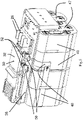
- FIG. 4-6 the battery pack described above is shown with its housing removed to reveal the frames 40 and the circuit board 38 of the battery pack.
- the terminal holder 32 is also illustrated to have been installed on the circuit board 38 .
- the four frames 40 are align substantially in a head-to-tail manner which together forms an elongated shape of the battery pack.
- Each frame 40 contains a plurality of thorough holes 45 where each such thorough hole 45 is used to accommodate one battery cell 42 .
- the battery cell 42 has a cylindrical shape. Multiple battery cells 42 in the same frame 40 are connected by metal strips 47 so as to connect the battery cells 42 in parallel.
- connecting bars 48 which extend along the exterior surface of the frames 40 .
- the connecting bars 48 are made of thin metal strips, which have shapes closely fitting the exterior shape of the portions of frames 40 along which the connecting bar 48 extends.
- Each connecting bar 48 extends from an end of a frame 40 to the circuit board 38 , where the battery cells 42 in different frames 40 are electrically connected to each other at the circuit board 38 , subject to the status of the configurable connectors.
- the aforementioned battery pins 26 are placed on the circuit board 38 and electrically connected to the circuit board 38 . Among the four battery pins 26 , there is a positive pin, a negative pin, a first signal pin, and a second signal pin.
- the configurable connectors can be switched between a first status and a second status, which ultimately control electrical connections between the different battery cells 42 .
- the first status is when the configurable connector is switched on, and the second status is when the configurable connector is switched off.
- the terminal holder 32 has an end plate 50 as mentioned above, the top surface of which is designed to be flush with the exterior shape of the battery housing in order to form a smooth appearance.
- On the other side of the end plate 50 there are three intermediate conductors 52 , and an actuating member 54 , which are substantially connected to the four corner positions of the end plate 50 .
- the intermediate conductors 52 and the actuating member 54 therefore extend from the end plate 50 to the circuit board 38 when the terminal holder 32 is installed.
- the intermediate conductor 52 is a metal pin in a thin plate shape.
- the shape of the intermediate conductor 52 allows it to be inserted between the two metal clips 58 of each configurable connector on the circuit board 38 .
- the actuating member 54 is a rod-like rigid component which is used to actuate the surface-mount switch 56 on the circuit board. Due to the end plate 50 , all three intermediate conductors 52 and the actuating member 54 are fixedly connected.
- the surface-mount switch 56 is a part of the internal electrical circuit of the battery pack and controls the on/off the electrical circuit.
- Figs. 7 and 8 show the metal clips 58 of the configurable connectors in more details.
- the surface-mount switch 56 is also shown in the two figures.
- Fig. 7 shows metal clips 58 in which the intermediate connector 52 is inserted (although the end plate of the terminal holder is not shown), and
- Fig. 8 shows metal clips 58 without the intermediate connector inserted therein.
- the two metal clips 58 are aligned to be in parallel to each other, and both extend upward from the circuit board 38.
- the metal clips 58 are also referred as terminals of each configurable connector.
- Each metal clip 58 is bent into a hook shape with a bent end 64 and a flat end 66 .
- the bent end 64 of the metal clip 58 is used for physically contacting with the intermediate conductor 52 , and since the metal clip 58 is made of thin metal, the bent end of the metal clip 58 is resilient which allows the intermediate conductor 52 to squeeze in but not easily falls out without applying an external force on the intermediate conductor 52 .
- On the flat end 66 of each metal clip 58 there is formed a tab 60 which is made to be parallel with the surface of the circuit board 38 .
- Each tab 60 is used to connect to a strap 62 of a connecting bar (not shown).
- the strap 62 is welded to a corresponding tab 60 , thus enabling electrical connection from the metal clip 58 to its tab 60 , the strap 62 , and in turn the electrical circuit of the battery pack.
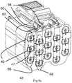
- Figs. 9a and 9b all the battery cells 42 in the battery pack are connected in groups to form ten battery sets in total.
- Each battery set 68 contains three battery cells 42 connected in parallel by metal strips 47 . Therefore, ideally each battery set 68 in Figs. 9a and 9b provide the same output voltage which is the voltage of a single battery cell 42 , but the current outputted by the battery set 68 is three times of that outputted by a single battery cell 42 .
- Fig. 9a there are five such battery sets 68 shown, and in Fig. 9b there are another five such battery sets 68 .
- the leftmost battery set 68 is connected to the leftmost metal clip 58 .
- a metal strip 47 has an end on which the above mentioned strap 62 is formed, and then the strap 62 is connected to the tab 60 of the corresponding metal clip 58 . Since there are only three pairs of metal clips 58 but there are ten battery sets 68 , this would mean that not every battery set 68 is directly connected to a configurable connector.
- the battery pack described above also contains a dummy holder 150 which has a shape similar to the terminal holder 50 but contains no intermediate conductors.
- the dummy holder 150 is intended as a separate piece of component to be used together with the battery pack.
- the dummy holder 150 is shown in Fig. 10 , which contains three dummy connectors 152 which are used to insert into the metal clips of the configurable connectors (not shown) to provide electrical insulation between two adjacent metal clips since the dummy connectors 152 are made of insulating materials.
- the dummy holder 150 can be inserted into the recess 33 of the protruded part 28 of the battery housing.
- the three dummy connectors 152 are connected to an end plate 132 of the dummy holder 150 .
- the end plate 132 is also formed with a snap-fit joint 136 at an end of the dummy holder 150 for the user to lift up the terminal holder 150 from the surface of the protruded part 28 and then remove the dummy holder 150 . Note that unlike the terminal holder described above, there is no actuating member in the dummy holder for triggering the surface-mount switch since the switch is not supposed to be triggered in any event when using a dummy holder.
- the configurable connector described above can be switched between a first status and a second status, depending on whether the terminal holder is inserted, or whether the dummy holder or otherwise nothing is inserted.
- the terminal holder In the first status of the configurable connector, the terminal holder is inserted into the configurable connector so that the metal plugs are electrically connected by the intermediate conductor in the terminal holder, and the configurable connector is switched on. The circuit segment containing the configurable connector is then closed and electrically connected.
- the second status of the configurable connector the dummy holder is inserted into the configurable connector, or actually nothing is inserted into the configurable connector, so that the metal plugs are not electrically connected.
- the configurable connector is switched off.
- the circuit segment containing the configurable connector is then open and not electrically connected.
- the simplified schematic diagram in Fig. 11 shows how ten battery sets 168 can be electrically connected with the three configurable connectors 170 for a battery pack similar to the one shown in Figs. 1-9b .
- all the battery sets 168 are effectively connected in series although among some of the connections between the battery sets 168 the configurable connectors 170 are present.
- Each configurable connector 170 contains two terminals 158 , such as the metal clips as described previously, and an intermediate conductor 152 .
- the three configurable connectors 170 are designated as jumpers JP1, JP2 and JP3 in the circuit diagram, and the ten battery sets 168 are designated as battery sets CL1 to CL10 respectively.
- the two battery pins 172 are the output of the battery pack which provides power or receives power from an external device such as an electric tool, or a battery charger.
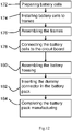
- Fig. 12 shows how the battery pack according to the present invention may be manufactured in factory prior to shipping and delivering to the end user.
- the most important feature of such manufacturing method compared to prior art is that once the battery pack manufactured, it is not ready for normal operation yet since the configurable connectors are not in a switched-on status.
- the battery pack only becomes operable when the user changes the configurable connectors to the switched-on status by inserting the terminal holder into the battery pack.
- the manufacturing method starts at Step 172 , where all the battery cells that are to be assembled in the battery pack are prepared, and in the example of Figs. 1-9b the number of required battery cells would be thirty.
- Step 174 the battery cells are assembled into the battery frames similar to those described above. Three battery cells in a column to be formed as one battery set, and these battery cells are also connected on their poles by metal strips in this step.
- Step 176 the four battery frames are assembled together by welding.
- the circuit board is connected to the battery frames and that necessary connecting bars are implemented along the exterior surface of the battery sets to connect the battery sets to each other and also to the circuit board.
- the connecting bars are sometimes welded together in order to extend from one battery set to another or to change it extending direction (e.g. a bent shape). Also, for some of the connecting bars their ends will be electrically connected to the metal clips in the configurable connectors similar to those described above.
- Step 180 the battery housing will be assembled so that the whole battery pack is made into its final appearance.
- the battery housing provides an internal wall as described above to protect the metal terminals of the configurable connectors from accidental short-circuiting or safety issue to the user
- Step 182 the dummy holder is inserted as an additional protection means and this dummy holder would completely insulate the two metal terminals in a configurable connector from each other and also from the outside environment.
- the manufacturing process of the battery pack is then completed in Step 184 , and it is ready to be shipped and sold to end users.
- Step 186 When the end user purchased or otherwise received the battery pack, he/she only has to perform a simple setup process to make the battery pack operational. As shown in Fig. 13 , the user in Step 186 firstly needs to remove the dummy holder that came along with the battery pack to the end user. Removal of the dummy holder does not instantly make the battery pack ready to work, but the user still needs to insert the terminal holder into the battery pack which electrically connects all the configurable connectors and also activates the switch button on the circuit board of the battery pack in Step 188 . Once the terminal holder is inserted, then the electrical circuit in the battery pack is completely closed and the battery pack is ready to use in Step 190 .
- Fig. 14 shows how the terminal holder 32 may be inserted into the protruded part 28 of the battery pack housing in order to activate the battery pack internal circuit in Step 188 above.
- the terminal holder 32 is not inserted into the recess 33 of the protruded part 28 along a straight-line direction. Rather, an end of the end plate 50 of the terminal holder 32 is firstly pressed against a corresponding end of the recess 33 .
- the terminal holder 32 is then rotated around that end (in a counterclockwise direction in Fig. 14 ), in the process which the intermediate connectors 52 are inserted into their respective metal clips 58 of the configurable connector, and the actuating member 54 engages the surface-mount switch 56 .
- the snap-fit joint 36 finally enters the recess and locks the terminal holder 32 due to the elasticity of the snap-fit joint 36 , the terminal holder 32 is finally installed in the battery pack.
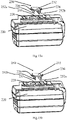
- Figs. 15a and 15b show a battery pack with a single, dual-purposes terminal holder according to a further embodiment of the present invention.
- a single piece of component can be used both as the terminal holder which activates the battery circuit, and as a dummy holder which deactivates the battery circuit and prevents it from accidently short-circuiting.
- the dual-purposes terminal holder 250 similar to the terminal holders and dummy holders described above, is made as a separate part which is removable from the battery housing.
- the dual-purposes terminal holder 250 has a substantially symmetrical shape on its two ends on which the dummy connectors 252b and the intermediate connectors 252a are configured. Both ends of the dual-purposes terminal holder 250 are formed with snap-fit joints 236 .
- the intermediate connectors 252a are made of conductors such as metal materials, and the dummy connectors 252b are made of insulating materials such as plastics.
- the dual-purposes terminal holder 250 is inserted into the recess 233 with its orientation as shown in Fig. 15a , the dummy connectors 252b are inserted into metal clips of each configurable connector (not shown) in the battery pack, while the intermediate connectors 252a are inserted into some other holes formed on the battery housing 220 which do not connect to any other component.
- the dual-purposes terminal holder 250 is used as a safety protection means which would completely insulate the two metal terminals in a configurable connector from each other and also from the outside environment.
- the dual-purposes terminal holder 250 is inserted into the recess 233 with its orientation as shown in Fig. 15b , then the positions of the dummy connectors 252b and intermediate connectors 252a are swapped.
- the intermediate connectors 252a are now inserted into metal clips of each configurable connector (not shown) in the battery pack, while the dummy connectors 252b are inserted into some other holes formed on the battery housing 220 which do not connect to any other component.
- the dual-purposes terminal holder 250 is used as just as a conducting part similar to the terminal holder mentioned previously, which would close the internal circuit of the battery pack and enables the battery pack to enter a ready-to-operate status.
- the battery cells in the battery pack as described in Figs. 1-9b above are accommodated in thorough holes in the battery frames.
- other structures and mechanisms may also be used according to the user's preference to install and fix the battery cells, including but not limited to non-encircling battery racks, heat shrink tubing, etc.
- the battery pack internal circuit is exemplified in Fig. 11 as ten battery sets connected in series. In each battery set the three battery cells are connected in parallel as exemplified in Figs. 9a and 9b .
- the battery cells can be configured in parallel, in serial, or in hybrid to form a battery set, and the battery sets can also be configured in parallel, in serial, or in hybrid.
- Figs. 1-9b and 11 there are three configurable connectors provided in the internal electrical circuit of the battery pack, which are used as circuit breakers at certain points between the battery sets.
- any number of configurable connector can be used in the battery pack as long as they serve the purpose of interrupting the electrical circuit in the battery pack unless terminal connectors are inserted.
- the terminal holder is configured as a separate component which can be freely detached or attached to the battery pack.
- the terminal holder may also be made with different structures.
- the terminal holder can be attached to the battery pack housing using resilient belts.
- a specific manufacturing procedure is shown as an example for the battery packs according to the present invention, including certain steps of installing battery cells and frames in sequence.
- these steps are not limited as such, and that their orders can also be altered.
- the key point of the present invention falls onto the use of configurable connectors, and the arrangement of battery cells or their method of assembling can be varied according to particular applications on need.
- the examples of the battery pack above use a dummy connector in place where the battery pack is not intended to be put into operation.
- the dummy connector is fully optional, and even without such dummy connector the internal wall of the battery housing would serve, to some extents, the purpose of avoid short or safety issues of the metal terminals in the configurable connectors.
Landscapes
- Chemical & Material Sciences (AREA)
- Chemical Kinetics & Catalysis (AREA)
- Electrochemistry (AREA)
- General Chemical & Material Sciences (AREA)
- Engineering & Computer Science (AREA)
- Microelectronics & Electronic Packaging (AREA)
- Manufacturing & Machinery (AREA)
- Inorganic Chemistry (AREA)
- Power Engineering (AREA)
- Battery Mounting, Suspending (AREA)
Claims (15)
- Bloc-batterie, comprenant :a) un boîtier ;b) un cadre reçu dans le boîtier ;c) deux éléments de batterie ou plus installés sur le cadre ; les deux éléments de batterie ou plus étant interconnectés par un connecteur configurable qui est configuré pour permettre des connexions électriques entre les deux éléments de batterie ou plus ; etd) un porte-bornes comprenant un conducteur intermédiaire ;dans lequel, le connecteur configurable est adapté pour être configuré pour passer d'un second état à un premier état ; dans le premier état, les deux éléments de batterie ou plus étant connectés électriquement ; dans le second état, les deux éléments de la batterie ou plus n'étant pas connectés électriquement ;dans lequel le connecteur configurable comprend en outre deux bornes qui sont séparées l'une de l'autre et connectées respectivement à l'un des deux ou plusieurs éléments de batterie ; les deux bornes n'étant pas connectées électriquement et le connecteur configurable se trouvant ainsi dans le second état, à moins que les deux bornes ne soient connectées par le conducteur intermédiaire, moyennant quoi le connecteur configurable se retrouve dans le premier état ;dans lequel le conducteur intermédiaire est connecté de manière détachable aux deux bornes du connecteur configurable ;dans lequel le porte-bornes est installé de manière amovible sur le boîtier et est adapté pour être soulevé du boîtier par un utilisateur.
- Bloc-batterie selon la revendication 1, dans lequel les deux bornes sont des pinces métalliques agencées pour être parallèles l'une à l'autre ; le conducteur intermédiaire comprenant une broche métallique insérée de manière détachable entre les deux pinces métalliques de sorte que les deux bornes deviennent connectées électriquement et que le connecteur configurable se retrouve dans le premier état.
- Bloc-batterie selon la revendication 1, comprenant en outre deux connecteurs configurables ou plus ; les conducteurs intermédiaires des deux connecteurs configurables ou plus sont reliés entre eux de manière fixe.
- Bloc-batterie selon la revendication 1, comprenant en outre un connecteur factice, le connecteur factice étant connecté de manière détachable aux deux bornes et provoquant l'isolation électrique des deux bornes et comprenant en outre, éventuellement, deux connecteurs configurables ou plus ; le bloc-batterie comprenant en outre deux connecteurs factices ou plus qui sont reliés entre eux de manière fixe.
- Bloc-batterie selon la revendication 1, comprenant en outre une carte de circuit imprimé à laquelle sont fixées les deux bornes du connecteur configurable.
- Bloc-batterie selon la revendication 1, comprenant en outre un commutateur pour commander un circuit électrique du bloc-batterie ; le conducteur intermédiaire étant en outre relié à un élément d'actionnement adapté pour déclencher le commutateur ; le commutateur étant activé ou désactivé lorsque le conducteur intermédiaire se connecte ou se déconnecte des deux bornes,et éventuellement dans lequel le commutateur est un bouton-poussoir,et comprenant en outre éventuellement une carte de circuit imprimé sur laquelle le circuit électrique est mis en oeuvre ; le commutateur étant monté en surface sur la carte de circuit imprimé.
- Bloc-batterie selon la revendication 1, dans lequel le boîtier loge le cadre et les deux éléments de batterie ou plus ; le boîtier comprenant en outre une partie qui protège les deux bornes du connecteur configurable contre un contact accidentel avec des objets extérieurs ; la partie du boîtier étant formée avec une ouverture qui permet le contact avec les deux bornes par le conducteur intermédiaire.
- Bloc-batterie selon la revendication 1, dans lequel le connecteur intermédiaire est un connecteur à double usage qui est adapté soit pour connecter électriquement les deux bornes du connecteur configurable, soit pour ne pas provoquer la connexion électrique des deux bornes,
et éventuellement dans lequel le connecteur à double usage comprend un élément conducteur et un élément isolant qui sont configurés symétriquement sur deux extrémités du connecteur à double usage respectivement. - Procédé de fabrication d'un bloc-batterie, comprenant les étapes consistant à :a) assembler le bloc-batterie en installant deux éléments de batterie ou plus sur un cadre reçu dans un boîtier ; etb) connecter les deux éléments de batterie ou plus par un connecteur configurable qui est configuré pour passer d'un second état à un premier état ; le connecteur configurable comprenant en outre deux bornes qui sont séparées l'une de l'autre ; les deux bornes n'étant pas connectées électriquement et le connecteur configurable étant dans le second état, de sorte que les deux éléments de batterie ou plus ne sont pas connectés électriquement ;dans lequel les deux bornes sont adaptées pour être connectées par un conducteur intermédiaire externe sur un porte-bornes, moyennant quoi le connecteur configurable se retrouve dans le premier état, le porte-bornes étant installé de manière amovible sur le boîtier et étant adapté pour être soulevé du boîtier par un utilisateur.
- Procédé selon la revendication 9,dans lequel les deux bornes sont deux pinces métalliques positionnées en parallèle ; le conducteur intermédiaire comprenant une broche métallique ; les deux pinces métalliques étant adaptées pour recevoir la broche métallique insérée entre les deux pinces métalliques de sorte que les deux bornes deviennent connectées électriquement,ou dans lequel le connecteur intermédiaire est un connecteur à double usage qui est adapté soit pour connecter électriquement les deux bornes du connecteur configurable, soit pour ne pas provoquer la connexion électrique des deux bornes et éventuellement dans lequel le connecteur à double usage comprend un élément conducteur et un élément isolant qui sont configurés symétriquement sur deux extrémités du connecteur à double usage respectivement.
- Procédé selon la revendication 9,dans lequel les deux bornes sont adaptées pour recevoir un connecteur factice inséré entre elles, ce qui n'entraîne pas la connexion électrique des deux bornes,oudans lequel le bloc-batterie comprend en outre une carte de circuit imprimé à laquelle les deux bornes sont fixées,oudans lequel le boîtier loge le cadre et les deux éléments de batterie ou plus ; le boîtier comprenant en outre une partie qui couvre les deux bornes du connecteur configurable contre un contact accidentel avec des objets extérieurs ; la partie du boîtier étant formée avec une ouverture qui permet le contact avec les deux bornes par le conducteur intermédiaire.
- Procédé de mise en service d'un bloc-batterie, comprenant les étapes consistant à :a) préparer un bloc-batterie qui comprend :i) un boîtier ;ii) un cadre reçu dans le boîtier ; etiii) deux éléments de batterie ou plus installés sur le cadre ; les deux éléments de batterie ou plus étant interconnectés par un connecteur configurable qui est configuré pour passer d'un second état à un premier état ; le connecteur configurable comprenant en outre deux bornes qui sont séparées l'une de l'autre et non connectées électriquement et le connecteur configurable étant dans le second état, de sorte que les deux éléments de batterie ou plus ne sont pas connectés électriquement ; etiv) un porte-bornes comprenant un conducteur intermédiaire ;b) connecter les deux bornes du connecteur conducteur par le conducteur intermédiaire, moyennant quoi le connecteur configurable se retrouve dans le premier état et les deux éléments de batterie ou plus deviennent connectés électriquement, le porte-bornes étant installé de manière amovible sur le boîtier et étant adapté pour être soulevé du boîtier par un utilisateur.
- Procédé selon la revendication 12,dans lequel les deux bornes sont des pinces métalliques positionnées en parallèle ; le conducteur intermédiaire comprenant une broche métallique insérée de manière détachable entre les deux pinces métalliques de sorte que les deux bornes deviennent connectées électriquement,oudans lequel le bloc-batterie comprend en outre un connecteur factice connecté de manière détachable aux deux bornes et provoquant l'isolation électrique des deux bornes ; le procédé comprend en outre l'étape consistant à déconnecter le connecteur factice du connecteur configurable avant l'étape de connexion,oudans lequel le bloc-batterie comprend en outre une carte de circuit imprimé à laquelle les deux bornes sont fixées.
- Procédé selon la revendication 12,dans lequel le bloc-batterie comprend en outre un commutateur pour commander un circuit électrique du bloc-batterie ; le conducteur intermédiaire étant en outre relié à un élément d'actionnement adapté pour déclencher le commutateur ; le commutateur étant activé lors de l'étape de connexion lorsque le conducteur intermédiaire se connecte aux deux bornes,et éventuellement dans lequel le commutateur est un bouton-poussoir,et en outre, éventuellement, dans lequel le bloc-batterie comprend en outre une carte de circuit imprimé sur laquelle le circuit électrique est mis en oeuvre ; le commutateur étant monté en surface sur la carte de circuit imprimé,ou dans lequel le boîtier loge le cadre et les deux éléments de batterie ou plus ; le boîtier comprenant en outre une partie qui couvre les deux bornes du connecteur configurable contre un contact accidentel avec des objets extérieurs ; la partie du boîtier étant formée avec une ouverture qui permet le contact avec les deux bornes par le conducteur intermédiaire.
- Procédé selon la revendication 12, dans lequel le connecteur intermédiaire est un connecteur à double usage qui est adapté soit pour connecter électriquement les deux bornes du connecteur configurable, soit pour ne pas provoquer la connexion électrique des deux bornes,
et éventuellement dans lequel le connecteur à double usage comprend un élément conducteur et un élément isolant qui sont configurés symétriquement sur deux extrémités du connecteur à double usage respectivement.
Applications Claiming Priority (1)
| Application Number | Priority Date | Filing Date | Title |
|---|---|---|---|
| PCT/CN2016/074731 WO2017143597A1 (fr) | 2016-02-26 | 2016-02-26 | Blocs-batteries et procédé d'assemblage de blocs-batteries |
Publications (3)
| Publication Number | Publication Date |
|---|---|
| EP3378113A1 EP3378113A1 (fr) | 2018-09-26 |
| EP3378113A4 EP3378113A4 (fr) | 2019-07-10 |
| EP3378113B1 true EP3378113B1 (fr) | 2022-11-30 |
Family
ID=58029092
Family Applications (2)
| Application Number | Title | Priority Date | Filing Date |
|---|---|---|---|
| EP16891051.1A Active EP3378113B1 (fr) | 2016-02-26 | 2016-02-26 | Blocs-batteries et procédé d'assemblage de blocs-batteries |
| EP17836345.3A Active EP3381074B1 (fr) | 2016-02-26 | 2017-07-28 | Bloc-batterie |
Family Applications After (1)
| Application Number | Title | Priority Date | Filing Date |
|---|---|---|---|
| EP17836345.3A Active EP3381074B1 (fr) | 2016-02-26 | 2017-07-28 | Bloc-batterie |
Country Status (8)
| Country | Link |
|---|---|
| US (2) | US11196095B2 (fr) |
| EP (2) | EP3378113B1 (fr) |
| CN (2) | CN109075299B (fr) |
| AU (2) | AU2016394097B2 (fr) |
| CA (2) | CA3008493C (fr) |
| MX (2) | MX388053B (fr) |
| TW (2) | TWM553895U (fr) |
| WO (2) | WO2017143597A1 (fr) |
Families Citing this family (26)
| Publication number | Priority date | Publication date | Assignee | Title |
|---|---|---|---|---|
| USD776610S1 (en) * | 2014-04-22 | 2017-01-17 | Briggs & Stratton Corporation | Battery |
| AU2016394097B2 (en) * | 2016-02-26 | 2020-02-20 | Tti (Macao Commercial Offshore) Limited | Battery packs and method of assembling battery packs |
| USD841572S1 (en) | 2016-03-08 | 2019-02-26 | Briggs & Stratton Corporation | Battery |
| US10965133B2 (en) * | 2016-12-16 | 2021-03-30 | Defond Electech Co., Ltd. | Battery pack system for electrically connecting a battery pack to a machine |
| CN211062817U (zh) * | 2016-12-16 | 2020-07-21 | 米沃奇电动工具公司 | 电池组 |
| CN211455740U (zh) | 2016-12-16 | 2020-09-08 | 米沃奇电动工具公司 | 电池组、接口、电气组合、闩锁机构、弹出器、双动作闩锁机构和减震组件 |
| EP3913723A1 (fr) | 2017-03-24 | 2021-11-24 | Milwaukee Electric Tool Corporation | Configuration de terminal pour bloc-batterie |
| TWM578899U (zh) | 2017-06-30 | 2019-06-01 | 美商米沃奇電子工具公司 | 電氣組合、動力工具系統、電動馬達總成、電動馬達、電池組以及馬達總成 |
| DE102017119705A1 (de) * | 2017-08-28 | 2019-02-28 | Robert Bosch Gmbh | Energiespeichersystem mit einem in einen passiven Zustand schaltbaren Energiespeicher |
| MX2020008197A (es) * | 2018-02-12 | 2020-09-22 | Techtronic Cordless Gp | Paquete de baterias que contiene conector giratorio. |
| USD887980S1 (en) | 2018-02-16 | 2020-06-23 | Milwaukee Electric Tool Corporation | Interface portion of a battery pack |
| DE102018206883A1 (de) * | 2018-05-04 | 2019-11-07 | Robert Bosch Gmbh | Akkupack |
| WO2020077618A1 (fr) | 2018-10-19 | 2020-04-23 | Tti (Macao Commercial Offshore) Limited | Blocs-batteries comportant un support de borne configurable |
| EP3981035A1 (fr) | 2019-06-06 | 2022-04-13 | Sew-Eurodrive GmbH & Co. KG | Unité de stockage d'énergie avec boîtier et connecteur de pontage |
| US11424504B2 (en) * | 2019-08-09 | 2022-08-23 | Techtronic Cordless Gp | Battery pack support portion configured to accommodate multiple different device interfaces |
| USD1013634S1 (en) | 2019-09-05 | 2024-02-06 | Techtronic Cordless Gp | Battery pack |
| US11355807B2 (en) * | 2020-01-17 | 2022-06-07 | Bloom Energy Corporation | Shippable battery module and method |
| CN214848862U (zh) * | 2020-07-27 | 2021-11-23 | 浙江动一新能源动力科技股份有限公司 | 多用电池包 |
| JP7681998B2 (ja) * | 2021-03-25 | 2025-05-23 | パナソニックエナジー株式会社 | 電池パック |
| USD1114724S1 (en) | 2022-03-08 | 2026-02-24 | Milwaukee Electric Tool Corporation | Battery pack |
| US20230369872A1 (en) * | 2022-05-12 | 2023-11-16 | Techtronic Cordless Gp | Robotic tool and charging station |
| USD1065046S1 (en) | 2022-09-16 | 2025-03-04 | Briggs & Stratton, Llc | Battery |
| USD1106072S1 (en) | 2023-02-09 | 2025-12-16 | Briggs & Stratton, Llc | Battery pack connector |
| USD1118483S1 (en) | 2023-06-29 | 2026-03-17 | Milwaukee Electric Tool Corporation | Battery pack |
| USD1120861S1 (en) | 2023-07-12 | 2026-03-31 | Milwaukee Electric Tool Corporation | Battery pack |
| USD1086988S1 (en) * | 2023-07-19 | 2025-08-05 | Carlos Bolsi Gavagnin | Battery pack |
Family Cites Families (24)
| Publication number | Priority date | Publication date | Assignee | Title |
|---|---|---|---|---|
| US5308715A (en) * | 1993-08-19 | 1994-05-03 | Grumman Aerospace Corporation | Aircraft system battery pack |
| TW447153B (en) | 1999-06-07 | 2001-07-21 | Matsushita Electric Industrial Co Ltd | Storage battery |
| JP4211276B2 (ja) * | 2002-04-23 | 2009-01-21 | パナソニック電工株式会社 | 充電式電気機器 |
| JP2007520180A (ja) | 2003-10-14 | 2007-07-19 | ブラック アンド デッカー インク | 電池パックの障害状態からの保護を提供するべく適合された二次電池、電動工具、充電器、及び電池パック用の保護方法、保護回路、及び保護装置 |
| KR100560498B1 (ko) | 2004-05-19 | 2006-03-14 | 삼성에스디아이 주식회사 | 이차 전지와 이를 이용한 전지 모듈 |
| JP4869588B2 (ja) * | 2004-12-17 | 2012-02-08 | 株式会社日立製作所 | 電源システム |
| JP4333715B2 (ja) * | 2006-09-07 | 2009-09-16 | 日立工機株式会社 | 電池パック、充電器、及び電動工具 |
| CN101758488B (zh) * | 2008-10-30 | 2012-07-04 | 苏州宝时得电动工具有限公司 | 电动工具以及电动工具和电池包的组合 |
| TWM376916U (en) | 2009-09-04 | 2010-03-21 | Cheng Uei Prec Ind Co Ltd | Battery connector |
| CN101662036B (zh) * | 2009-09-16 | 2012-01-18 | 华为终端有限公司 | 电池 |
| JP5577802B2 (ja) | 2010-04-07 | 2014-08-27 | 日産自動車株式会社 | 電池モジュール |
| US8709628B2 (en) * | 2010-09-02 | 2014-04-29 | Bathium Canada Inc. | Battery pack with connecting device |
| JP5803259B2 (ja) * | 2011-05-17 | 2015-11-04 | 日産自動車株式会社 | 電気自動車のバッテリパック構造 |
| EP2838138B1 (fr) * | 2012-04-12 | 2019-02-27 | Kabushiki Kaisha Toyota Jidoshokki | Interrupteur de courant et dispositif de stockage électrique l'utilisant |
| US9318729B2 (en) * | 2013-04-05 | 2016-04-19 | Makita Corporation | Power tool battery pack |
| JP6039490B2 (ja) * | 2013-04-16 | 2016-12-07 | 日本航空電子工業株式会社 | コネクタおよび組電池 |
| WO2014206323A1 (fr) * | 2013-06-26 | 2014-12-31 | Techtronic Power Tools Technology Limited | Bloc-batterie, batterie d'outil et outil actionné par batterie |
| JP2015095594A (ja) * | 2013-11-13 | 2015-05-18 | 新神戸電機株式会社 | 電気化学セルモジュール及び電気化学セルモジュール用のホルダ |
| KR102106447B1 (ko) * | 2013-12-09 | 2020-05-04 | 삼성에스디아이 주식회사 | 전지 모듈 |
| US9577230B2 (en) * | 2014-03-27 | 2017-02-21 | Ford Global Technologies, Llc | Integrated high voltage service disconnect for traction batteries |
| KR102249889B1 (ko) * | 2014-04-07 | 2021-05-07 | 삼성에스디아이 주식회사 | 이차 전지용 보호 장치 |
| CN105576725B (zh) * | 2014-10-15 | 2018-03-16 | 台达电子工业股份有限公司 | 备援供电装置、其电池总成及其充放电控制方法 |
| CN105336907B (zh) * | 2015-11-09 | 2018-11-27 | 金龙联合汽车工业(苏州)有限公司 | 电动汽车电池组内电池箱或电池模组之间的电接头结构 |
| AU2016394097B2 (en) * | 2016-02-26 | 2020-02-20 | Tti (Macao Commercial Offshore) Limited | Battery packs and method of assembling battery packs |
-
2016
- 2016-02-26 AU AU2016394097A patent/AU2016394097B2/en active Active
- 2016-02-26 EP EP16891051.1A patent/EP3378113B1/fr active Active
- 2016-02-26 MX MX2018007784A patent/MX388053B/es unknown
- 2016-02-26 WO PCT/CN2016/074731 patent/WO2017143597A1/fr not_active Ceased
- 2016-02-26 CA CA3008493A patent/CA3008493C/fr active Active
- 2016-02-26 CN CN201680079666.8A patent/CN109075299B/zh active Active
- 2016-02-26 US US16/065,996 patent/US11196095B2/en active Active
- 2016-08-04 CN CN201620839421.8U patent/CN205985178U/zh active Active
-
2017
- 2017-02-21 TW TW106202505U patent/TWM553895U/zh unknown
- 2017-02-24 TW TW106106386A patent/TWI746522B/zh active
- 2017-07-28 EP EP17836345.3A patent/EP3381074B1/fr active Active
- 2017-07-28 WO PCT/CN2017/094937 patent/WO2018024163A1/fr not_active Ceased
- 2017-07-28 MX MX2018009102A patent/MX388778B/es unknown
- 2017-07-28 CA CA3012910A patent/CA3012910A1/fr active Pending
- 2017-07-28 AU AU2017306457A patent/AU2017306457B2/en active Active
- 2017-07-28 US US16/072,358 patent/US10950830B2/en active Active
Also Published As
| Publication number | Publication date |
|---|---|
| CN109075299A (zh) | 2018-12-21 |
| EP3378113A1 (fr) | 2018-09-26 |
| US20190020072A1 (en) | 2019-01-17 |
| MX388053B (es) | 2025-03-19 |
| CA3008493C (fr) | 2023-07-04 |
| EP3381074A4 (fr) | 2019-08-14 |
| WO2018024163A1 (fr) | 2018-02-08 |
| TWI746522B (zh) | 2021-11-21 |
| TW201806217A (zh) | 2018-02-16 |
| US10950830B2 (en) | 2021-03-16 |
| AU2017306457A1 (en) | 2018-07-05 |
| MX388778B (es) | 2025-03-20 |
| MX2018009102A (es) | 2018-09-03 |
| US20190081290A1 (en) | 2019-03-14 |
| WO2017143597A1 (fr) | 2017-08-31 |
| MX2018007784A (es) | 2019-09-06 |
| AU2016394097B2 (en) | 2020-02-20 |
| EP3381074B1 (fr) | 2025-07-09 |
| US11196095B2 (en) | 2021-12-07 |
| AU2016394097A1 (en) | 2018-07-05 |
| CA3008493A1 (fr) | 2017-08-31 |
| CA3012910A1 (fr) | 2018-02-08 |
| AU2017306457B2 (en) | 2020-04-02 |
| EP3378113A4 (fr) | 2019-07-10 |
| EP3381074C0 (fr) | 2025-07-09 |
| CN109075299B (zh) | 2021-08-31 |
| CN205985178U (zh) | 2017-02-22 |
| TWM553895U (zh) | 2018-01-01 |
| EP3381074A1 (fr) | 2018-10-03 |
Similar Documents
| Publication | Publication Date | Title |
|---|---|---|
| EP3378113B1 (fr) | Blocs-batteries et procédé d'assemblage de blocs-batteries | |
| US20260024866A1 (en) | Battery Pack Containing A Rotatable Connector | |
| US7300297B1 (en) | Power supply with a changeable plug | |
| CN109713764B (zh) | 电池包 | |
| TW202017230A (zh) | 包含可配置端子座的電池組 | |
| JP2001126607A (ja) | 分岐回路遮断器の付加機能ユニット | |
| JP2020017533A (ja) | プラグのアタッチメント | |
| CN215343231U (zh) | 一种多用电子连接器 | |
| CN210378918U (zh) | 一种低压塑壳断路器 | |
| TWI389406B (zh) | Security multimeter connector | |
| CN210040803U (zh) | 改进型多功能电源插排 | |
| CN109119811B (zh) | 容易更换的开关插座、电连接组件及面板组件 | |
| CN101859671A (zh) | 动力电池熔断器 | |
| KR200374898Y1 (ko) | 외부 충격에 강한 플러그 연결 소자 | |
| JP2002064940A (ja) | 携帯電子機器の多連充電装置 | |
| CN2917016Y (zh) | 电源插座之安全重置装置 | |
| KR20100019782A (ko) | 멀티퓨즈 | |
| KR200374899Y1 (ko) | 외부 충격에 강한 플러그 연결 소자 | |
| GB2439979A (en) | Power supply with exchangeable plug | |
| KR19980056580U (ko) | 다양한 플러그핀을 구비한 소켓용 플러그 | |
| JP2007265952A (ja) | 雷保護機能付防雨コンセント |
Legal Events
| Date | Code | Title | Description |
|---|---|---|---|
| STAA | Information on the status of an ep patent application or granted ep patent |
Free format text: STATUS: THE INTERNATIONAL PUBLICATION HAS BEEN MADE |
|
| PUAI | Public reference made under article 153(3) epc to a published international application that has entered the european phase |
Free format text: ORIGINAL CODE: 0009012 |
|
| STAA | Information on the status of an ep patent application or granted ep patent |
Free format text: STATUS: REQUEST FOR EXAMINATION WAS MADE |
|
| 17P | Request for examination filed |
Effective date: 20180622 |
|
| AK | Designated contracting states |
Kind code of ref document: A1 Designated state(s): AL AT BE BG CH CY CZ DE DK EE ES FI FR GB GR HR HU IE IS IT LI LT LU LV MC MK MT NL NO PL PT RO RS SE SI SK SM TR |
|
| AX | Request for extension of the european patent |
Extension state: BA ME |
|
| DAV | Request for validation of the european patent (deleted) | ||
| DAX | Request for extension of the european patent (deleted) | ||
| A4 | Supplementary search report drawn up and despatched |
Effective date: 20190611 |
|
| RIC1 | Information provided on ipc code assigned before grant |
Ipc: H01M 2/10 20060101ALI20190604BHEP Ipc: H01M 2/20 20060101AFI20190604BHEP Ipc: H01M 2/30 20060101ALI20190604BHEP Ipc: H01M 10/42 20060101ALI20190604BHEP Ipc: H01M 2/02 20060101ALI20190604BHEP |
|
| RAP1 | Party data changed (applicant data changed or rights of an application transferred) |
Owner name: TTI (MACAO COMMERCIAL OFFSHORE) LIMITED |
|
| RAP1 | Party data changed (applicant data changed or rights of an application transferred) |
Owner name: TECHTRONIC OUTDOOR PRODUCTS TECHNOLOGY LIMITED |
|
| REG | Reference to a national code |
Ref country code: DE Ref legal event code: R079 Ref document number: 602016076696 Country of ref document: DE Free format text: PREVIOUS MAIN CLASS: H01M0002200000 Ipc: H01M0050200000 |
|
| GRAP | Despatch of communication of intention to grant a patent |
Free format text: ORIGINAL CODE: EPIDOSNIGR1 |
|
| STAA | Information on the status of an ep patent application or granted ep patent |
Free format text: STATUS: GRANT OF PATENT IS INTENDED |
|
| RIC1 | Information provided on ipc code assigned before grant |
Ipc: H01M 50/50 20210101ALI20220805BHEP Ipc: H01M 50/28 20210101ALI20220805BHEP Ipc: H01M 10/42 20060101ALI20220805BHEP Ipc: H01M 50/20 20210101AFI20220805BHEP |
|
| INTG | Intention to grant announced |
Effective date: 20220912 |
|
| GRAS | Grant fee paid |
Free format text: ORIGINAL CODE: EPIDOSNIGR3 |
|
| GRAA | (expected) grant |
Free format text: ORIGINAL CODE: 0009210 |
|
| STAA | Information on the status of an ep patent application or granted ep patent |
Free format text: STATUS: THE PATENT HAS BEEN GRANTED |
|
| AK | Designated contracting states |
Kind code of ref document: B1 Designated state(s): AL AT BE BG CH CY CZ DE DK EE ES FI FR GB GR HR HU IE IS IT LI LT LU LV MC MK MT NL NO PL PT RO RS SE SI SK SM TR |
|
| REG | Reference to a national code |
Ref country code: CH Ref legal event code: EP Ref country code: GB Ref legal event code: FG4D |
|
| REG | Reference to a national code |
Ref country code: AT Ref legal event code: REF Ref document number: 1535382 Country of ref document: AT Kind code of ref document: T Effective date: 20221215 |
|
| REG | Reference to a national code |
Ref country code: IE Ref legal event code: FG4D |
|
| REG | Reference to a national code |
Ref country code: DE Ref legal event code: R096 Ref document number: 602016076696 Country of ref document: DE |
|
| REG | Reference to a national code |
Ref country code: LT Ref legal event code: MG9D |
|
| REG | Reference to a national code |
Ref country code: NL Ref legal event code: MP Effective date: 20221130 |
|
| PG25 | Lapsed in a contracting state [announced via postgrant information from national office to epo] |
Ref country code: SE Free format text: LAPSE BECAUSE OF FAILURE TO SUBMIT A TRANSLATION OF THE DESCRIPTION OR TO PAY THE FEE WITHIN THE PRESCRIBED TIME-LIMIT Effective date: 20221130 Ref country code: PT Free format text: LAPSE BECAUSE OF FAILURE TO SUBMIT A TRANSLATION OF THE DESCRIPTION OR TO PAY THE FEE WITHIN THE PRESCRIBED TIME-LIMIT Effective date: 20230331 Ref country code: NO Free format text: LAPSE BECAUSE OF FAILURE TO SUBMIT A TRANSLATION OF THE DESCRIPTION OR TO PAY THE FEE WITHIN THE PRESCRIBED TIME-LIMIT Effective date: 20230228 Ref country code: LT Free format text: LAPSE BECAUSE OF FAILURE TO SUBMIT A TRANSLATION OF THE DESCRIPTION OR TO PAY THE FEE WITHIN THE PRESCRIBED TIME-LIMIT Effective date: 20221130 Ref country code: FI Free format text: LAPSE BECAUSE OF FAILURE TO SUBMIT A TRANSLATION OF THE DESCRIPTION OR TO PAY THE FEE WITHIN THE PRESCRIBED TIME-LIMIT Effective date: 20221130 Ref country code: ES Free format text: LAPSE BECAUSE OF FAILURE TO SUBMIT A TRANSLATION OF THE DESCRIPTION OR TO PAY THE FEE WITHIN THE PRESCRIBED TIME-LIMIT Effective date: 20221130 |
|
| REG | Reference to a national code |
Ref country code: AT Ref legal event code: MK05 Ref document number: 1535382 Country of ref document: AT Kind code of ref document: T Effective date: 20221130 |
|
| PG25 | Lapsed in a contracting state [announced via postgrant information from national office to epo] |
Ref country code: RS Free format text: LAPSE BECAUSE OF FAILURE TO SUBMIT A TRANSLATION OF THE DESCRIPTION OR TO PAY THE FEE WITHIN THE PRESCRIBED TIME-LIMIT Effective date: 20221130 Ref country code: PL Free format text: LAPSE BECAUSE OF FAILURE TO SUBMIT A TRANSLATION OF THE DESCRIPTION OR TO PAY THE FEE WITHIN THE PRESCRIBED TIME-LIMIT Effective date: 20221130 Ref country code: LV Free format text: LAPSE BECAUSE OF FAILURE TO SUBMIT A TRANSLATION OF THE DESCRIPTION OR TO PAY THE FEE WITHIN THE PRESCRIBED TIME-LIMIT Effective date: 20221130 Ref country code: IS Free format text: LAPSE BECAUSE OF FAILURE TO SUBMIT A TRANSLATION OF THE DESCRIPTION OR TO PAY THE FEE WITHIN THE PRESCRIBED TIME-LIMIT Effective date: 20230330 Ref country code: HR Free format text: LAPSE BECAUSE OF FAILURE TO SUBMIT A TRANSLATION OF THE DESCRIPTION OR TO PAY THE FEE WITHIN THE PRESCRIBED TIME-LIMIT Effective date: 20221130 Ref country code: GR Free format text: LAPSE BECAUSE OF FAILURE TO SUBMIT A TRANSLATION OF THE DESCRIPTION OR TO PAY THE FEE WITHIN THE PRESCRIBED TIME-LIMIT Effective date: 20230301 |
|
| PG25 | Lapsed in a contracting state [announced via postgrant information from national office to epo] |
Ref country code: NL Free format text: LAPSE BECAUSE OF FAILURE TO SUBMIT A TRANSLATION OF THE DESCRIPTION OR TO PAY THE FEE WITHIN THE PRESCRIBED TIME-LIMIT Effective date: 20221130 |
|
| PG25 | Lapsed in a contracting state [announced via postgrant information from national office to epo] |
Ref country code: SM Free format text: LAPSE BECAUSE OF FAILURE TO SUBMIT A TRANSLATION OF THE DESCRIPTION OR TO PAY THE FEE WITHIN THE PRESCRIBED TIME-LIMIT Effective date: 20221130 Ref country code: RO Free format text: LAPSE BECAUSE OF FAILURE TO SUBMIT A TRANSLATION OF THE DESCRIPTION OR TO PAY THE FEE WITHIN THE PRESCRIBED TIME-LIMIT Effective date: 20221130 Ref country code: EE Free format text: LAPSE BECAUSE OF FAILURE TO SUBMIT A TRANSLATION OF THE DESCRIPTION OR TO PAY THE FEE WITHIN THE PRESCRIBED TIME-LIMIT Effective date: 20221130 Ref country code: DK Free format text: LAPSE BECAUSE OF FAILURE TO SUBMIT A TRANSLATION OF THE DESCRIPTION OR TO PAY THE FEE WITHIN THE PRESCRIBED TIME-LIMIT Effective date: 20221130 Ref country code: CZ Free format text: LAPSE BECAUSE OF FAILURE TO SUBMIT A TRANSLATION OF THE DESCRIPTION OR TO PAY THE FEE WITHIN THE PRESCRIBED TIME-LIMIT Effective date: 20221130 Ref country code: AT Free format text: LAPSE BECAUSE OF FAILURE TO SUBMIT A TRANSLATION OF THE DESCRIPTION OR TO PAY THE FEE WITHIN THE PRESCRIBED TIME-LIMIT Effective date: 20221130 |
|
| PG25 | Lapsed in a contracting state [announced via postgrant information from national office to epo] |
Ref country code: SK Free format text: LAPSE BECAUSE OF FAILURE TO SUBMIT A TRANSLATION OF THE DESCRIPTION OR TO PAY THE FEE WITHIN THE PRESCRIBED TIME-LIMIT Effective date: 20221130 Ref country code: AL Free format text: LAPSE BECAUSE OF FAILURE TO SUBMIT A TRANSLATION OF THE DESCRIPTION OR TO PAY THE FEE WITHIN THE PRESCRIBED TIME-LIMIT Effective date: 20221130 |
|
| REG | Reference to a national code |
Ref country code: DE Ref legal event code: R097 Ref document number: 602016076696 Country of ref document: DE |
|
| PG25 | Lapsed in a contracting state [announced via postgrant information from national office to epo] |
Ref country code: MC Free format text: LAPSE BECAUSE OF FAILURE TO SUBMIT A TRANSLATION OF THE DESCRIPTION OR TO PAY THE FEE WITHIN THE PRESCRIBED TIME-LIMIT Effective date: 20221130 |
|
| REG | Reference to a national code |
Ref country code: CH Ref legal event code: PL |
|
| PLBE | No opposition filed within time limit |
Free format text: ORIGINAL CODE: 0009261 |
|
| STAA | Information on the status of an ep patent application or granted ep patent |
Free format text: STATUS: NO OPPOSITION FILED WITHIN TIME LIMIT |
|
| REG | Reference to a national code |
Ref country code: BE Ref legal event code: MM Effective date: 20230228 |
|
| PG25 | Lapsed in a contracting state [announced via postgrant information from national office to epo] |
Ref country code: LU Free format text: LAPSE BECAUSE OF NON-PAYMENT OF DUE FEES Effective date: 20230226 Ref country code: LI Free format text: LAPSE BECAUSE OF NON-PAYMENT OF DUE FEES Effective date: 20230228 Ref country code: CH Free format text: LAPSE BECAUSE OF NON-PAYMENT OF DUE FEES Effective date: 20230228 |
|
| 26N | No opposition filed |
Effective date: 20230831 |
|
| PG25 | Lapsed in a contracting state [announced via postgrant information from national office to epo] |
Ref country code: SI Free format text: LAPSE BECAUSE OF FAILURE TO SUBMIT A TRANSLATION OF THE DESCRIPTION OR TO PAY THE FEE WITHIN THE PRESCRIBED TIME-LIMIT Effective date: 20221130 |
|
| REG | Reference to a national code |
Ref country code: IE Ref legal event code: MM4A |
|
| PG25 | Lapsed in a contracting state [announced via postgrant information from national office to epo] |
Ref country code: IE Free format text: LAPSE BECAUSE OF NON-PAYMENT OF DUE FEES Effective date: 20230226 |
|
| PG25 | Lapsed in a contracting state [announced via postgrant information from national office to epo] |
Ref country code: BE Free format text: LAPSE BECAUSE OF NON-PAYMENT OF DUE FEES Effective date: 20230228 |
|
| PG25 | Lapsed in a contracting state [announced via postgrant information from national office to epo] |
Ref country code: IT Free format text: LAPSE BECAUSE OF FAILURE TO SUBMIT A TRANSLATION OF THE DESCRIPTION OR TO PAY THE FEE WITHIN THE PRESCRIBED TIME-LIMIT Effective date: 20221130 |
|
| PG25 | Lapsed in a contracting state [announced via postgrant information from national office to epo] |
Ref country code: BG Free format text: LAPSE BECAUSE OF FAILURE TO SUBMIT A TRANSLATION OF THE DESCRIPTION OR TO PAY THE FEE WITHIN THE PRESCRIBED TIME-LIMIT Effective date: 20221130 |
|
| PG25 | Lapsed in a contracting state [announced via postgrant information from national office to epo] |
Ref country code: BG Free format text: LAPSE BECAUSE OF FAILURE TO SUBMIT A TRANSLATION OF THE DESCRIPTION OR TO PAY THE FEE WITHIN THE PRESCRIBED TIME-LIMIT Effective date: 20221130 |
|
| PG25 | Lapsed in a contracting state [announced via postgrant information from national office to epo] |
Ref country code: CY Free format text: LAPSE BECAUSE OF FAILURE TO SUBMIT A TRANSLATION OF THE DESCRIPTION OR TO PAY THE FEE WITHIN THE PRESCRIBED TIME-LIMIT; INVALID AB INITIO Effective date: 20160226 |
|
| PG25 | Lapsed in a contracting state [announced via postgrant information from national office to epo] |
Ref country code: HU Free format text: LAPSE BECAUSE OF FAILURE TO SUBMIT A TRANSLATION OF THE DESCRIPTION OR TO PAY THE FEE WITHIN THE PRESCRIBED TIME-LIMIT; INVALID AB INITIO Effective date: 20160226 |
|
| PG25 | Lapsed in a contracting state [announced via postgrant information from national office to epo] |
Ref country code: TR Free format text: LAPSE BECAUSE OF FAILURE TO SUBMIT A TRANSLATION OF THE DESCRIPTION OR TO PAY THE FEE WITHIN THE PRESCRIBED TIME-LIMIT Effective date: 20221130 |
|
| PGFP | Annual fee paid to national office [announced via postgrant information from national office to epo] |
Ref country code: GB Payment date: 20260227 Year of fee payment: 11 |
|
| PGFP | Annual fee paid to national office [announced via postgrant information from national office to epo] |
Ref country code: DE Payment date: 20260227 Year of fee payment: 11 |
|
| PGFP | Annual fee paid to national office [announced via postgrant information from national office to epo] |
Ref country code: FR Payment date: 20260225 Year of fee payment: 11 |