EP3378512B1 - Pompe médicale, procédé de commande de pompe médicale, et programme de commande de pompe médicale - Google Patents
Pompe médicale, procédé de commande de pompe médicale, et programme de commande de pompe médicale Download PDFInfo
- Publication number
- EP3378512B1 EP3378512B1 EP16866459.7A EP16866459A EP3378512B1 EP 3378512 B1 EP3378512 B1 EP 3378512B1 EP 16866459 A EP16866459 A EP 16866459A EP 3378512 B1 EP3378512 B1 EP 3378512B1
- Authority
- EP
- European Patent Office
- Prior art keywords
- unit
- battery
- power
- abnormality
- power supply
- Prior art date
- Legal status (The legal status is an assumption and is not a legal conclusion. Google has not performed a legal analysis and makes no representation as to the accuracy of the status listed.)
- Active
Links
Images




Classifications
-
- A—HUMAN NECESSITIES
- A61—MEDICAL OR VETERINARY SCIENCE; HYGIENE
- A61M—DEVICES FOR INTRODUCING MEDIA INTO, OR ONTO, THE BODY; DEVICES FOR TRANSDUCING BODY MEDIA OR FOR TAKING MEDIA FROM THE BODY; DEVICES FOR PRODUCING OR ENDING SLEEP OR STUPOR
- A61M5/00—Devices for bringing media into the body in a subcutaneous, intra-vascular or intramuscular way; Accessories therefor, e.g. filling or cleaning devices, arm-rests
- A61M5/14—Infusion devices, e.g. infusing by gravity; Blood infusion; Accessories therefor
- A61M5/142—Pressure infusion, e.g. using pumps
- A61M5/14212—Pumping with an aspiration and an expulsion action
- A61M5/14228—Pumping with an aspiration and an expulsion action with linear peristaltic action, i.e. comprising at least three pressurising members or a helical member
-
- A—HUMAN NECESSITIES
- A61—MEDICAL OR VETERINARY SCIENCE; HYGIENE
- A61M—DEVICES FOR INTRODUCING MEDIA INTO, OR ONTO, THE BODY; DEVICES FOR TRANSDUCING BODY MEDIA OR FOR TAKING MEDIA FROM THE BODY; DEVICES FOR PRODUCING OR ENDING SLEEP OR STUPOR
- A61M2205/00—General characteristics of the apparatus
- A61M2205/17—General characteristics of the apparatus with redundant control systems
-
- A—HUMAN NECESSITIES
- A61—MEDICAL OR VETERINARY SCIENCE; HYGIENE
- A61M—DEVICES FOR INTRODUCING MEDIA INTO, OR ONTO, THE BODY; DEVICES FOR TRANSDUCING BODY MEDIA OR FOR TAKING MEDIA FROM THE BODY; DEVICES FOR PRODUCING OR ENDING SLEEP OR STUPOR
- A61M2205/00—General characteristics of the apparatus
- A61M2205/18—General characteristics of the apparatus with alarm
-
- A—HUMAN NECESSITIES
- A61—MEDICAL OR VETERINARY SCIENCE; HYGIENE
- A61M—DEVICES FOR INTRODUCING MEDIA INTO, OR ONTO, THE BODY; DEVICES FOR TRANSDUCING BODY MEDIA OR FOR TAKING MEDIA FROM THE BODY; DEVICES FOR PRODUCING OR ENDING SLEEP OR STUPOR
- A61M2205/00—General characteristics of the apparatus
- A61M2205/50—General characteristics of the apparatus with microprocessors or computers
-
- A—HUMAN NECESSITIES
- A61—MEDICAL OR VETERINARY SCIENCE; HYGIENE
- A61M—DEVICES FOR INTRODUCING MEDIA INTO, OR ONTO, THE BODY; DEVICES FOR TRANSDUCING BODY MEDIA OR FOR TAKING MEDIA FROM THE BODY; DEVICES FOR PRODUCING OR ENDING SLEEP OR STUPOR
- A61M2205/00—General characteristics of the apparatus
- A61M2205/82—Internal energy supply devices
- A61M2205/8206—Internal energy supply devices battery-operated
-
- A—HUMAN NECESSITIES
- A61—MEDICAL OR VETERINARY SCIENCE; HYGIENE
- A61M—DEVICES FOR INTRODUCING MEDIA INTO, OR ONTO, THE BODY; DEVICES FOR TRANSDUCING BODY MEDIA OR FOR TAKING MEDIA FROM THE BODY; DEVICES FOR PRODUCING OR ENDING SLEEP OR STUPOR
- A61M2205/00—General characteristics of the apparatus
- A61M2205/82—Internal energy supply devices
- A61M2205/8262—Internal energy supply devices connectable to external power source, e.g. connecting to automobile battery through the cigarette lighter
Definitions
- the present invention relates to a medical pump for delivering a medication liquid or the like to a patient or the like, a medical pump control method, and a medical pump control program.
- medical pumps such as infusion pumps and syringe pumps are conventionally used to precisely control, for example, a dosage, an administration rate, or the like of a medication liquid when the medication liquid is administered to a patient (for example, Patent Literature 1) .
- Such a medical pump is electrically driven, and thus, typically includes an "AC adapter cable” incorporating an “AC adapter” that converts an alternate current (AC) power supply supplied from an outlet to direct current to be applied for a medical pump.
- AC alternate current
- the medical pump has a built-in battery so as to be able to operate without using the AC adapter cable.
- Patent Literature 1 JP 2002-113099 A US 2012/150114 discloses a battery management system for one or more batteries. Further relevant prior art can be found in US 4,692,145 A , and US 2011/0184383 A1 .
- a medical pump including: an external power acquisition unit that acquires power from the outside; two battery units capable of supplying power without intervention of the external power acquisition unit, wherein the two battery units include a first battery unit and a second battery unit, wherein the second battery unit is an auxiliary battery unit that supplies power in place of the first battery unit; an AC power supply connection information processing unit, that determines whether the power acquisition unit is connected to a power supply; a first battery connection management unit and a second battery connection management unit, that detect whether the first and/or second battery is in a disconnected state; and an abnormality information storage unit that stores abnormality information of the external power acquisition unit and the two battery units, wherein the abnormality information includes that the external power acquisition unit is not connected to an outlet to acquire power from the outside, the first battery unit is disconnected, and the second battery unit is disconnected wherein when abnormality information, detecting disconnection of any two of the external power acquisition unit and the two battery units is stored in the abnormality information storage unit, power supply abnormality state information is output
- an external power acquisition unit for example, an AC power supply unit such as an AC adapter cable
- two battery units for example, a main battery and a sub battery
- the other battery unit supplies power, making it possible to maintain operation or the like of the medical pump, leading to prevention of an occurrence of a serious problem on a patient or the like using the medical pump.
- the above configuration outputs power supply abnormality state information (for example, power supply abnormality information) when abnormality information of any two of the external power acquisition unit and the two battery units is stored in the abnormality information storage unit.
- power supply abnormality state information for example, power supply abnormality information
- the two battery units include a first battery unit and a second battery unit, and a power exhaustion state in which the power stored in the first battery unit lowers to a predetermined level or below with difficulty in supplying a certain level of power is not included in the abnormality information.
- the power exhaustion state in which the power stored in the first battery unit (for example, the main battery) lowers to a predetermined level or below with difficulty in supplying a certain level of power is not included in the abnormality information.
- first battery unit exhaustion state information representing an exhaustion state of the first battery unit and second battery unit exhaustion state information representing an exhaustion state of the second battery unit are stored, and when both of the first battery unit exhaustion state information and the second battery unit exhaustion state information are present, warning information that there is a need to continue acquisition of power from the external power acquisition unit is output.
- warning information for example, "Do not unplug the AC cable” or the like
- the first battery unit exhaustion state information is not included in the "abnormality information", and thus, when both the first battery unit exhaustion state information and the second battery unit exhaustion state information are present, that is, when the battery unit and the auxiliary battery unit both have difficulty in supplying the power, the power supply abnormality state information would not be output, and thus, there is a possibility that the user or the like would stop using the external power acquisition unit (for example, unplugs the AC adapter cable from the outlet).
- the above-described configuration in this case outputs warning information that there is a need to continue acquisition of power from the external power acquisition unit, so as to enable the user to maintain the use of the external power acquisition unit to prevent sudden stop or the like of operation of the medical pump.
- the second battery unit is an auxiliary battery unit that supplies power in place of the first battery unit.
- the present invention is provided to achieve the above object by a method for controlling a medical pump including: an external power acquisition unit that acquires power from the outside; a battery unit capable of supplying power without intervention of the external power acquisition unit; an auxiliary battery unit that supplies power in place of the battery unit; and an abnormality information storage unit that stores abnormality information of the external power acquisition unit, the battery unit, and the auxiliary battery unit, in which when abnormality information of any two of the external power acquisition unit, the battery unit, and the auxiliary battery unit is stored in the abnormality information storage unit, power supply abnormality state information is output.
- a medical pump control program that causes a medical pump including: an external power acquisition unit that acquires power from the outside; a battery unit capable of supplying power without intervention of the external power acquisition unit; an auxiliary battery unit that supplies power in place of the battery unit; and an abnormality information storage unit that stores abnormality information of the external power acquisition unit, the battery unit, and the auxiliary battery unit, to execute a step of outputting power supply abnormality state information when abnormality information of any two of the external power acquisition unit, the battery unit, and the auxiliary battery unit is stored in the abnormality information storage unit.
- a medical pump As described above, according to the present invention, it is possible to provide a medical pump, a medical pump control method, and a medical pump control program capable of alerting in advance the user or the like to the stoppage of the operation of the medical pump, or the like.
- Fig. 1 is a schematic diagram illustrating a main configuration of an infusion pump 10 as an exemplary medical pump.
- the infusion pump 10 includes: a display 11 as a display unit that displays a variety of information; and various operation buttons 12.
- the various operation buttons 12 arranged include: a pilot lamp 12a that contains an LED and indicates operation states of the infusion pump 10 with light emission and display via a light diffusing agent; a fast delivery switch button 12b for injecting a medication liquid at an injection rate faster than a set flow rate (mL/h); a start switch button 12c; a stop switch button 12d; and a menu selection button 12e.
- the infusion pump 10 also includes a liquid delivery driving unit 30 that operates such as applying pressure on a tube 13 as an exemplary tube portion arranged inside the infusion pump 10, so as to deliver medication liquid therein.
- a liquid delivery driving unit 30 that operates such as applying pressure on a tube 13 as an exemplary tube portion arranged inside the infusion pump 10, so as to deliver medication liquid therein.
- the medication liquid delivered by the liquid delivery driving unit 30 is administered to a patient or the like with high accuracy.
- Fig. 2 is a schematic illustration of a main configuration of the liquid delivery driving unit 30 of the infusion pump 10 illustrated in Fig. 1 .
- the liquid delivery driving unit 30 includes a cam structure 32 and a finger structure 33, and liquid delivery of the medication liquid in the tube 13 is controlled with these structures.
- delivery of the medication liquid in the tube 13 is controlled with high accuracy by the operation of the cam structure 32.
- the cam structure 32 includes a plurality of cams, for example, six cams 32a to 32f, while the finger structure 33 includes six fingers 33a to 33f corresponding to the six cams 32a to 32f respectively.
- the six cams 32a to 32f are arranged with a phase difference from each other, and the cam structure 32 is coupled to an output shaft 14a of a drive motor 14.
- the plurality of fingers 33a to 33f is individually driven via the cams 32a to 32f respectively in the Y-direction in Fig. 2 so as to sequentially press an outer peripheral surface of the tube 13 in a T direction in Fig. 2 to deliver the medication liquid in the tube 13.
- the liquid delivery driving unit 30 controls a peristaltic-like movement of the plurality of fingers 33a to 33f to sequentially move the fingers 33a to 33f forward/backward to move a blocking point within the tube 13 in the T direction as if waves propagate so as to squeeze the tube 13 to transfer the medication liquid.
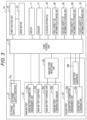
- Fig. 3 is a schematic block diagram illustrating a main configuration of the infusion pump 10 of Fig. 1 .
- the infusion pump 10 includes a "pump control unit 15".
- the pump control unit 15 controls a "pump function unit 16" that controls the drive motor 14 or the like illustrated in Fig. 2 .
- the pump control unit 15 also controls a "speaker 17" that output voice or the like and a “clocking apparatus 18" or the like, in addition to the display 11 illustrated in Fig. 1 .
- the pump control unit 15 controls: an AC power supply unit 21 as an exemplary external power acquisition unit; a main battery 22 as an exemplary first battery unit; a sub battery 23 as an exemplary second battery unit or an auxiliary battery unit; and a main battery monitoring unit 24, or the like.
- the pump control unit 15 also controls a "first variety of information storage unit 40", a "second variety of information storage unit 50", a “third variety of information storage unit 60” and a "fourth variety of information storage unit 70". These configurations will be described below.
- the AC power supply unit 21 includes an AC power supply substrate 21a and also includes an AC adapter cable connected to an outlet or the like in practice.
- the main battery 22 is a battery that stores electricity inside, and is used as a power supply source when the AC adapter cable of the AC power supply unit 21 is not connected to an outlet, or the like. Moreover, the main battery 22 is rechargeable via the AC power supply unit 21.
- the main battery 22 includes a "main battery connection management unit 22a".
- the main battery connection management unit 22a can grasp whether the main battery 22 is in a disconnected state, or the like, due to line breakage, connector disengagement, or the like.
- the main battery 22 includes a "main battery substrate 22b", and further includes a “main battery charging unit 22c” that manages a charging state or the like of the main battery 22, and a “main battery temperature sensor 22d” that measures the temperature of the main battery 22.
- the main battery monitoring unit 24 acquires "battery life determination data", “charge abnormality determination data”, “battery remaining capacity data” or the like from the main battery charging unit 22c, while acquiring "temperature sensor data” from the "main battery temperature sensor 22d".
- the sub battery 23 is a battery used in place of the main battery 22 when the main battery 22 has difficulty in supplying power.
- the sub battery 23 is rechargeable via the AC power supply unit 21 and includes a "sub battery connection management unit 23a" so as to be able to grasp whether the sub battery 23 is in a disconnected state, or the like, due to line breakage, connector disengagement, or the like.
- the sub battery 23 also includes a "sub battery substrate 23b", and a “sub battery charging unit 23c" that manages the charging state or the like.
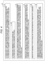
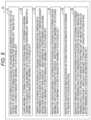
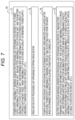
- Figs. 4 to 7 are schematic block diagrams illustrating main configurations of the "first variety of information storage unit 40", the "second variety of information storage unit 50", the “third variety of information storage unit 60" and the “fourth variety of information storage unit 70" in Fig. 3 . The specific configuration of these will be described below.
- the infusion pump 10 illustrated in Fig. 1 has a computer including a central processing unit (CPU), a random access memory (RAM), and a read only memory (ROM) (these are not illustrated), being connected to each other via a bus.
- CPU central processing unit
- RAM random access memory
- ROM read only memory
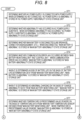
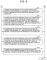
- Figs. 8 to 11 are schematic flowcharts illustrating a main operation example or the like of the infusion pump 10 according to the present embodiment.
- the infusion pump 10 acquires information of the AC power supply unit 21, the main battery 22, the sub battery 23, or the like in Fig. 3 during operation (during liquid delivery). Details will be described below.
- Steps of Figs. 8 and 9 are numbered for the sake of convenience, and these steps may be executed in order or simultaneously.
- step (hereinafter referred to as "ST") 1 the "AC power supply connection confirmation processing unit (program) 41" in Fig. 4 operates and determines whether the "AC power supply unit 21" is connected to the power supply. Specifically, in a case where the AC adapter cable is not connected to the outlet, it is determined as “abnormality", for example, and "AC power supply is abnormal” is stored in the "AC power supply abnormality state storage unit 42" as an exemplary abnormality information storage unit in Fig. 4 .
- the infusion pump 10 uses the AC power supply unit 21 in normal use, having the main battery 22 as a supplementary power supply for the time when the AC power supply unit 21 is not available such as during movement and power failure. In this sense, the case where the AC adapter cable is not connected to an outlet is included in "abnormality".
- processing proceeds to ST 3.
- the "main battery connection state management unit (program) 44" in Fig. 4 operates and determines whether the main battery 22 is disconnected, for example, whether line breakage or connector disengagement has occurred. In the case of disconnection, "main battery is abnormal” is stored in the "main battery abnormality state storage unit 45" in Fig. 4 .
- the processing proceeds to ST 4.
- the "communication error determination processing unit (program) 46" in Fig. 4 operates and determines whether a communication error has occurred between the "main battery monitoring unit 24" and the “pump control unit 15" or the like in Fig. 3 .
- "main battery is abnormal” is stored in the "main battery abnormality state storage unit 45" in Fig. 4 .
- the processing proceeds to ST 5.
- the "main battery life determination processing unit (program) 51" in Fig. 5 operates.
- “battery life determination data” such as data of the transition of the charge amount from the "main battery monitoring unit 24" in Fig. 3
- "main battery is abnormal” is stored in the "main battery abnormality state storage unit 45" in Fig. 4 .
- the processing proceeds to ST 6.
- the "charge abnormality determination processing unit (program) 52" in Fig. 5 operates.
- charge abnormality data such as data of the transition of the charge amount from the "main battery monitoring unit 24" in Fig. 3
- main battery is abnormal is stored in the "main battery abnormality state storage unit 45" in Fig. 4 .
- the processing proceeds to ST 7.
- the "temperature determination processing unit (program) 53" in Fig. 5 operates and determines whether the temperature is a predetermined value or more on the basis of temperature data from the "main battery temperature sensor" acquired from the "main battery monitoring unit 24" in Fig. 3 . In a case where the temperature is the predetermined value or more, "main battery is abnormal” is stored in the "main battery abnormality state storage unit 45" in Fig. 4 .
- the processing proceeds to ST8.
- the "main battery substrate abnormality determination processing unit (program) 54" in Fig. 5 operates and determines whether an abnormality has occurred in the main battery substrate 22b. In a case where it is determined that the abnormality has occurred, "main battery is abnormal” is stored in the "main battery abnormality state storage unit 45" in Fig. 4 .
- main battery remaining capacity exhaustion determination processing unit (program) 55 in Fig. 5 operates and refers to “main battery remaining capacity data” acquired from the "main battery monitoring unit 24" in Fig. 3 and refers to the "main battery exhaustion information storage unit 56" in Fig. 5 .
- the main battery exhaustion information storage unit 56 stores threshold information such as a numerical value for determining that the main battery 22 is in an exhaustion state.
- the main battery remaining capacity exhaustion determination processing unit (program) 55 determines whether the battery remaining capacity data corresponds to "exhaustion” on the basis of these.
- "exhaustion” information is stored in in the "main battery remaining capacity exhaustion information storage unit 61" in Fig. 6 .
- the "exhaustion” information is exemplary first battery unit side exhaustion state information corresponding to an exemplary exhaustion state (power exhaustion state in which power stored in the battery unit lowers to a predetermined level or below with difficulty in supplying a certain level of power).
- the power exhaustion state is not included in the abnormality information.
- the processing proceeds to ST10.
- the "sub battery connection state management unit (program) 62" in Fig. 6 operates and determines whether the "sub battery 23" in Fig. 3 is disconnected, for example, whether line breakage or connector disengagement has occurred. In the case of disconnection, "sub battery is abnormal” is stored in the "sub battery abnormality state storage unit 63" in Fig. 6 .
- the processing proceeds to ST11.
- the "sub battery remaining capacity exhaustion determination processing unit (program) 64" in Fig. 6 operates and refers to the "sub battery remaining battery remaining capacity data" from the "sub battery charging unit 23c" and refers to the "sub battery exhaustion information storage unit 65" in Fig. 6 .
- the sub battery exhaustion information storage unit 65 stores threshold information such as a numerical value for determining that the sub battery 23 is in the exhaustion state.
- the sub battery remaining capacity exhaustion determination processing unit (program) 64 determines whether the battery remaining capacity data corresponds to "exhaustion” on the basis of these. When the data corresponds to "exhaustion”, "sub battery is abnormal” is stored in the "sub battery abnormality state storage unit 63" in Fig. 6 .
- This "exhaustion” information is exemplary second battery unit side exhaustion state information.
- this step also stores "exhaustion abnormality" as specific description of abnormality.
- the sub battery 23 is intended to be used at emergency and thus is not assumed to be exhausted in normal use. Therefore, the case where the sub battery 23 is in the exhaustion state is determined as "abnormality", unlike the main battery 22.
- sub battery substrate abnormality determination processing unit (program) 66" in Fig. 6 operates and determines whether an abnormality has occurred in the "sub battery substrate 23b" in Fig. 3 . In a case where it is determined that the abnormality has occurred, "sub battery is abnormal” is stored in the "sub battery abnormality state storage unit 63" in Fig. 6 .
- the infusion pump 10 that executes steps of acquisition, determination, and storage or the like of the information of the AC power supply unit 21, the main battery 22, the sub battery 23 or the like in Fig. 3 to be executed during operation of the pump (during liquid delivery).
- the following will describe steps of issuing warning or the like by the infusion pump 10 using such information.
- the processing proceeds to ST 21 of Fig. 10 .
- the "power supply abnormality warning generation processing unit (program) 71" in Fig. 7 operates and refers to the "AC power supply abnormality state storage unit 42", the “main battery abnormality state storage unit 45" in Fig. 4 and the “sub battery abnormality state storage unit 63" in Fig. 6 , and determines whether "abnormality" data is stored in a plurality of storage units among these storage units.
- ST 22 determines whether "abnormality” information is stored in a plurality of storage units, that is, whether “abnormality” data is stored in any two storage units among the "AC power supply abnormality state storage unit 42", the “main battery abnormality state storage unit 45", and the "sub battery abnormality state storage unit 63".
- the processing proceeds to ST 23.
- the "drive motor stop processing unit (program) 72" in Fig. 7 operates to stop the drive motor 14. Note that the stop of the drive motor 14 may be performed before the occurrence of a power supply abnormality warning or at the same time as the stop of the drive motor 14.
- the present embodiment includes the sub battery 23 in addition to the AC power supply unit 21 and the main battery 22. Accordingly, even in a case where there is a failure or the like in the AC power supply unit 21 and the main battery 22, or in a case where the AC adapter cable of the AC power supply unit 21 is unplugged from the outlet when the main battery 22 is faulty or the like, the sub battery 23 supplies power.
- the processing proceeds to ST 25.
- the "power supply processing unit (program) 74" in Fig. 7 operates and determines whether three minutes have elapsed after displaying a "power supply abnormality warning" as exemplary power supply abnormality state information on the "display 11" and outputting voice from the "speaker 17".
- the main battery 22 is configured so as not to include the power exhaustion state in the abnormality information, as described above.
- the processing proceeds to ST 28.
- the "battery exhaustion warning generation processing unit (program) 73" in Fig. 7 operates and refers to the "main battery remaining capacity exhaustion information storage unit 61" and the “sub battery abnormality state storage unit 63" in Fig. 6 , and determines whether “exhaustion information” is stored in the “main battery remaining capacity exhaustion information storage unit 61" and whether “exhaustion abnormality” is stored in the "sub battery abnormality state storage unit 63".
- ST 29 determines whether "exhaustion information” is stored in both the “main battery remaining capacity exhaustion information storage unit 61" and the “sub battery abnormality state storage unit 63", and when it is stored, processing proceeds to ST 30.
- ST 30 displays a message such as "Do not unplug AC cable” or "Do not unplug AC cable due to insufficient charge” on the display 11 as warning information, for example.
- the present embodiment is not limited to this and may use a step of first outputting a "power supply abnormality warning" to the display 11 and the speaker 17 and thereafter stopping the operation of the drive motor 14.
- the warning information that there is a need to continue acquisition of power from the AC adapter cable is output, enabling the user to maintain the use of the AC adapter cable and enabling prevention of a sudden stop or the like of the operation of the infusion pump 10.
- the present invention is not limited to the above-described embodiment. While the present embodiment describes the infusion pump 10 as an exemplary medical pump, the present invention is not limited to this. It is allowable to use a "syringe pump" that delivers a medication liquid in a syringe by moving a syringe pusher.
- the above-described embodiment is a case of using the main battery and the sub battery used when the sub battery has difficulty in supplying power, it is also allowable to configure such that two batteries operate in parallel to provide assistance at the time when the AC power supply is in an abnormal state, or when one of the two batteries fails, the other battery may supply power.
Landscapes
- Health & Medical Sciences (AREA)
- Vascular Medicine (AREA)
- Engineering & Computer Science (AREA)
- Anesthesiology (AREA)
- Biomedical Technology (AREA)
- Heart & Thoracic Surgery (AREA)
- Hematology (AREA)
- Life Sciences & Earth Sciences (AREA)
- Animal Behavior & Ethology (AREA)
- General Health & Medical Sciences (AREA)
- Public Health (AREA)
- Veterinary Medicine (AREA)
- Infusion, Injection, And Reservoir Apparatuses (AREA)
Claims (5)
- Pompe médicale comprenant :une unité d'acquisition d'énergie externe (21) qui acquiert de l'énergie de l'extérieur ;deux unités de batterie capables de fournir de l'énergie sans intervention de l'unité d'acquisition d'énergie externe, où les deux unités de batterie incluent une première unité de batterie (22) et une seconde unité de batterie (23), où la seconde unité de batterie (23) est une unité de batterie auxiliaire qui fournit de l'énergie à la place de la première unité de batterie (22) ;une unité de traitement d'informations de branchement d'alimentation électrique en courant alternatif, qui détermine si l'unité d'acquisition d'énergie (21) est branchée à une alimentation électrique ;une première unité de gestion de branchement de batterie et une seconde unité de gestion de branchement de batterie, qui détectent si la première batterie et/ou la seconde batterie est/sont dans un état débranché, respectivement ; etune unité de stockage d'informations d'anomalie (42, 45, 63) qui stocke des informations d'anomalie de l'unité d'acquisition d'énergie externe et des deux unités de batterie, caractérisée en ce queles informations d'anomalie incluent le fait que l'unité d'acquisition d'énergie externe (21) n'est pas branchée à une sortie pour acquérir de l'énergie de l'extérieur, que la première unité de batterie (22) est débranchée, et que la seconde unité de batterie (23) est débranchée ;où lorsque les informations d'anomalie, détectant le débranchement de deux quelconques unités parmi l'unité d'acquisition d'énergie externe (21) et des unités de batterie (22, 23), sont stockées dans l'unité de stockage d'informations d'anomalie (42, 45, 63), une information d'état d'anomalie d'alimentation électrique est fournie.
- Pompe médicale selon la revendication 1,
dans laquelle un état d'épuisement d'énergie dans lequel l'énergie stockée dans la première unité de batterie (22) descend à un niveau prédéterminé ou en dessous avec une difficulté à fournir un certain niveau d'énergie n'est pas inclus dans les informations d'anomalie. - Pompe médicale selon la revendication 2,dans laquelle des informations d'état d'épuisement de première unité de batterie représentant un état d'épuisement de la première unité de batterie (22) et des informations d'état d'épuisement de seconde unité de batterie représentant un état d'épuisement de la seconde unité de batterie (23) sont stockées, etlorsque à la fois les informations d'état d'épuisement de première unité de batterie et les informations d'état d'épuisement de seconde unité de batterie sont présentes, une information d'avertissement qu'il existe un besoin d'acquisition continue d'énergie depuis l'unité d'acquisition d'énergie externe (21) est fournie.
- Procédé de commande d'une pompe médicale qui comprendune unité d'acquisition d'énergie externe (21) qui acquiert de l'énergie de l'extérieur ;deux unités de batterie capables de fournir de l'énergie sans intervention de l'unité d'acquisition d'énergie externe, où les deux unités de batterie incluent une première unité de batterie (22) et une seconde unité de batterie (23), où la seconde unité de batterie (23) est une unité de batterie auxiliaire qui fournit de l'énergie à la place de la première unité de batterie (22) ;une unité de traitement d'informations de branchement d'alimentation électrique en courant alternatif, qui détermine si l'unité d'acquisition d'énergie (21) est branchée à une alimentation électrique ;une première unité de gestion de branchement de batterie et une seconde unité de gestion de branchement de batterie, qui détectent si la première unité de batterie et/ou la seconde unité de batterie est/sont dans un état débranché, respectivement ; etune unité de stockage d'informations d'anomalie (42, 45, 63) qui stocke des informations d'anomalie de l'unité d'acquisition d'énergie externe (21), de l'unité de batterie (22), et de l'unité de batterie auxiliaire (23), le procédé comprenant les étapes consistant à :déterminer, en utilisant l'unité de traitement d'informations de branchement d'alimentation électrique en courant alternatif, la première unité de gestion de branchement de batterie et la seconde unité de gestion de branchement de batterie, si l'alimentation électrique en courant alternatif est débranchée d'une sortie pour acquérir de l'énergie de l'extérieur, que la première unité de batterie (22) est débranchée, ou que l'unité de batterie auxiliaire (23) est débranchée ; etstocker les informations de débranchement en tant qu'informations d'anomalie dans l'unité de stockage d'informations d'anomalie (42, 45, 63) ;où lorsque des informations d'anomalie de deux quelconques unités parmi l'unité d'acquisition d'énergie externe (21), l'unité de batterie (22), et l'unité de batterie auxiliaire (23) sont stockées dans l'unité de stockage d'informations d'anomalie (42, 45, 63), une information d'état d'anomalie d'alimentation électrique est fournie.
- Programme de commande de pompe médicale qui, lorsqu'il est exécuté par un ordinateur de la pompe médicale, amène l'ordinateur à réaliser le procédé selon la revendication 4.
Applications Claiming Priority (2)
| Application Number | Priority Date | Filing Date | Title |
|---|---|---|---|
| JP2015227943 | 2015-11-20 | ||
| PCT/JP2016/084315 WO2017086459A1 (fr) | 2015-11-20 | 2016-11-18 | Pompe médicale, procédé de commande de pompe médicale, et programme de commande de pompe médicale |
Publications (3)
| Publication Number | Publication Date |
|---|---|
| EP3378512A1 EP3378512A1 (fr) | 2018-09-26 |
| EP3378512A4 EP3378512A4 (fr) | 2019-07-31 |
| EP3378512B1 true EP3378512B1 (fr) | 2024-06-19 |
Family
ID=58718981
Family Applications (1)
| Application Number | Title | Priority Date | Filing Date |
|---|---|---|---|
| EP16866459.7A Active EP3378512B1 (fr) | 2015-11-20 | 2016-11-18 | Pompe médicale, procédé de commande de pompe médicale, et programme de commande de pompe médicale |
Country Status (3)
| Country | Link |
|---|---|
| EP (1) | EP3378512B1 (fr) |
| JP (1) | JPWO2017086459A1 (fr) |
| WO (1) | WO2017086459A1 (fr) |
Families Citing this family (3)
| Publication number | Priority date | Publication date | Assignee | Title |
|---|---|---|---|---|
| WO2020149045A1 (fr) * | 2019-01-18 | 2020-07-23 | テルモ株式会社 | Pompe médicale |
| JP7314727B2 (ja) * | 2019-09-04 | 2023-07-26 | ニプロ株式会社 | 医療機器 |
| JP7459549B2 (ja) * | 2020-02-14 | 2024-04-02 | 株式会社ジェイ・エム・エス | 流量監視装置、輸液装置及び異常報知方法 |
Citations (2)
| Publication number | Priority date | Publication date | Assignee | Title |
|---|---|---|---|---|
| US4692145A (en) * | 1984-10-15 | 1987-09-08 | American Hospital Supply Corporation | Power system for infusion pumps |
| US20110184383A1 (en) * | 2008-10-06 | 2011-07-28 | Terumo Kabushiki Kaisha | Syringe pump |
Family Cites Families (2)
| Publication number | Priority date | Publication date | Assignee | Title |
|---|---|---|---|---|
| GB0020060D0 (en) | 2000-08-16 | 2000-10-04 | Smiths Industries Plc | Syringe pumps |
| ES2824836T3 (es) * | 2010-12-13 | 2021-05-13 | Baxter Int | Sistema de gestión de batería |
-
2016
- 2016-11-18 EP EP16866459.7A patent/EP3378512B1/fr active Active
- 2016-11-18 WO PCT/JP2016/084315 patent/WO2017086459A1/fr not_active Ceased
- 2016-11-18 JP JP2017551957A patent/JPWO2017086459A1/ja active Pending
Patent Citations (2)
| Publication number | Priority date | Publication date | Assignee | Title |
|---|---|---|---|---|
| US4692145A (en) * | 1984-10-15 | 1987-09-08 | American Hospital Supply Corporation | Power system for infusion pumps |
| US20110184383A1 (en) * | 2008-10-06 | 2011-07-28 | Terumo Kabushiki Kaisha | Syringe pump |
Also Published As
| Publication number | Publication date |
|---|---|
| EP3378512A1 (fr) | 2018-09-26 |
| EP3378512A4 (fr) | 2019-07-31 |
| WO2017086459A1 (fr) | 2017-05-26 |
| JPWO2017086459A1 (ja) | 2018-09-06 |
Similar Documents
| Publication | Publication Date | Title |
|---|---|---|
| US12128210B2 (en) | Multi-language/multi-processor infusion pump assembly | |
| EP2921190B1 (fr) | Pompe de distribution de liquide | |
| US20230263954A1 (en) | Infusion pump assembly with a backup power supply | |
| US20250046418A1 (en) | Error handling in infusion devices with distributed motor control and related operating methods | |
| EP3378512B1 (fr) | Pompe médicale, procédé de commande de pompe médicale, et programme de commande de pompe médicale | |
| JP6723154B2 (ja) | フェイルセーフ薬剤注入治療システム | |
| CN203710476U (zh) | 一种注射泵 | |
| US10137243B2 (en) | Infusion devices with distributed motor control and related operating methods | |
| ES2841120T3 (es) | Controlador de bomba remoto con comunicación bidireccional para comprobar el estado operativo de la bomba de insulina | |
| CN106921211A (zh) | 用于医疗器械的电源管理系统及其工作方法 | |
| CN103768670A (zh) | 一种人工心脏电源管理系统及其管理方法 | |
| US20220020485A1 (en) | Medical device having failsafe state machine | |
| CN111867655B (zh) | 药液注入系统、药液注入装置、药液注入方法以及程序 | |
| EP1515148A2 (fr) | Système et procédé pour alimentation de puissance par batteries de secours | |
| KR20150003147A (ko) | 내부 데이터 포트를 포함하는 배터리격실을 갖는 휴대용 주입펌프 | |
| JP2023540070A (ja) | 薬液注入装置、薬物注入装置及びその薬物残量を決定する方法 | |
| WO2025083105A1 (fr) | Dispositif médical économe en énergie | |
| JP2021040738A (ja) | ポンプ管理システム | |
| WO2025030128A2 (fr) | Systèmes et procédés de commande de moteur dans des dispositifs de perfusion |
Legal Events
| Date | Code | Title | Description |
|---|---|---|---|
| STAA | Information on the status of an ep patent application or granted ep patent |
Free format text: STATUS: THE INTERNATIONAL PUBLICATION HAS BEEN MADE |
|
| PUAI | Public reference made under article 153(3) epc to a published international application that has entered the european phase |
Free format text: ORIGINAL CODE: 0009012 |
|
| STAA | Information on the status of an ep patent application or granted ep patent |
Free format text: STATUS: REQUEST FOR EXAMINATION WAS MADE |
|
| 17P | Request for examination filed |
Effective date: 20180617 |
|
| AK | Designated contracting states |
Kind code of ref document: A1 Designated state(s): AL AT BE BG CH CY CZ DE DK EE ES FI FR GB GR HR HU IE IS IT LI LT LU LV MC MK MT NL NO PL PT RO RS SE SI SK SM TR |
|
| AX | Request for extension of the european patent |
Extension state: BA ME |
|
| DAV | Request for validation of the european patent (deleted) | ||
| DAX | Request for extension of the european patent (deleted) | ||
| A4 | Supplementary search report drawn up and despatched |
Effective date: 20190701 |
|
| RIC1 | Information provided on ipc code assigned before grant |
Ipc: A61M 5/145 20060101ALI20190625BHEP Ipc: A61M 5/142 20060101AFI20190625BHEP |
|
| STAA | Information on the status of an ep patent application or granted ep patent |
Free format text: STATUS: EXAMINATION IS IN PROGRESS |
|
| 17Q | First examination report despatched |
Effective date: 20220914 |
|
| GRAP | Despatch of communication of intention to grant a patent |
Free format text: ORIGINAL CODE: EPIDOSNIGR1 |
|
| STAA | Information on the status of an ep patent application or granted ep patent |
Free format text: STATUS: GRANT OF PATENT IS INTENDED |
|
| RIC1 | Information provided on ipc code assigned before grant |
Ipc: A61M 5/142 20060101AFI20231123BHEP |
|
| INTG | Intention to grant announced |
Effective date: 20231222 |
|
| GRAS | Grant fee paid |
Free format text: ORIGINAL CODE: EPIDOSNIGR3 |
|
| GRAA | (expected) grant |
Free format text: ORIGINAL CODE: 0009210 |
|
| STAA | Information on the status of an ep patent application or granted ep patent |
Free format text: STATUS: THE PATENT HAS BEEN GRANTED |
|
| AK | Designated contracting states |
Kind code of ref document: B1 Designated state(s): AL AT BE BG CH CY CZ DE DK EE ES FI FR GB GR HR HU IE IS IT LI LT LU LV MC MK MT NL NO PL PT RO RS SE SI SK SM TR |
|
| REG | Reference to a national code |
Ref country code: GB Ref legal event code: FG4D |
|
| REG | Reference to a national code |
Ref country code: CH Ref legal event code: EP |
|
| REG | Reference to a national code |
Ref country code: DE Ref legal event code: R096 Ref document number: 602016088060 Country of ref document: DE |
|
| PG25 | Lapsed in a contracting state [announced via postgrant information from national office to epo] |
Ref country code: BG Free format text: LAPSE BECAUSE OF FAILURE TO SUBMIT A TRANSLATION OF THE DESCRIPTION OR TO PAY THE FEE WITHIN THE PRESCRIBED TIME-LIMIT Effective date: 20240619 |
|
| PG25 | Lapsed in a contracting state [announced via postgrant information from national office to epo] |
Ref country code: FI Free format text: LAPSE BECAUSE OF FAILURE TO SUBMIT A TRANSLATION OF THE DESCRIPTION OR TO PAY THE FEE WITHIN THE PRESCRIBED TIME-LIMIT Effective date: 20240619 Ref country code: HR Free format text: LAPSE BECAUSE OF FAILURE TO SUBMIT A TRANSLATION OF THE DESCRIPTION OR TO PAY THE FEE WITHIN THE PRESCRIBED TIME-LIMIT Effective date: 20240619 |
|
| REG | Reference to a national code |
Ref country code: LT Ref legal event code: MG9D |
|
| PG25 | Lapsed in a contracting state [announced via postgrant information from national office to epo] |
Ref country code: GR Free format text: LAPSE BECAUSE OF FAILURE TO SUBMIT A TRANSLATION OF THE DESCRIPTION OR TO PAY THE FEE WITHIN THE PRESCRIBED TIME-LIMIT Effective date: 20240920 |
|
| REG | Reference to a national code |
Ref country code: NL Ref legal event code: MP Effective date: 20240619 |
|
| PG25 | Lapsed in a contracting state [announced via postgrant information from national office to epo] |
Ref country code: LV Free format text: LAPSE BECAUSE OF FAILURE TO SUBMIT A TRANSLATION OF THE DESCRIPTION OR TO PAY THE FEE WITHIN THE PRESCRIBED TIME-LIMIT Effective date: 20240619 |
|
| PG25 | Lapsed in a contracting state [announced via postgrant information from national office to epo] |
Ref country code: NO Free format text: LAPSE BECAUSE OF FAILURE TO SUBMIT A TRANSLATION OF THE DESCRIPTION OR TO PAY THE FEE WITHIN THE PRESCRIBED TIME-LIMIT Effective date: 20240919 Ref country code: LV Free format text: LAPSE BECAUSE OF FAILURE TO SUBMIT A TRANSLATION OF THE DESCRIPTION OR TO PAY THE FEE WITHIN THE PRESCRIBED TIME-LIMIT Effective date: 20240619 Ref country code: HR Free format text: LAPSE BECAUSE OF FAILURE TO SUBMIT A TRANSLATION OF THE DESCRIPTION OR TO PAY THE FEE WITHIN THE PRESCRIBED TIME-LIMIT Effective date: 20240619 Ref country code: GR Free format text: LAPSE BECAUSE OF FAILURE TO SUBMIT A TRANSLATION OF THE DESCRIPTION OR TO PAY THE FEE WITHIN THE PRESCRIBED TIME-LIMIT Effective date: 20240920 Ref country code: FI Free format text: LAPSE BECAUSE OF FAILURE TO SUBMIT A TRANSLATION OF THE DESCRIPTION OR TO PAY THE FEE WITHIN THE PRESCRIBED TIME-LIMIT Effective date: 20240619 Ref country code: BG Free format text: LAPSE BECAUSE OF FAILURE TO SUBMIT A TRANSLATION OF THE DESCRIPTION OR TO PAY THE FEE WITHIN THE PRESCRIBED TIME-LIMIT Effective date: 20240619 Ref country code: RS Free format text: LAPSE BECAUSE OF FAILURE TO SUBMIT A TRANSLATION OF THE DESCRIPTION OR TO PAY THE FEE WITHIN THE PRESCRIBED TIME-LIMIT Effective date: 20240919 |
|
| PG25 | Lapsed in a contracting state [announced via postgrant information from national office to epo] |
Ref country code: NL Free format text: LAPSE BECAUSE OF FAILURE TO SUBMIT A TRANSLATION OF THE DESCRIPTION OR TO PAY THE FEE WITHIN THE PRESCRIBED TIME-LIMIT Effective date: 20240619 |
|
| REG | Reference to a national code |
Ref country code: AT Ref legal event code: MK05 Ref document number: 1695519 Country of ref document: AT Kind code of ref document: T Effective date: 20240619 |
|
| PG25 | Lapsed in a contracting state [announced via postgrant information from national office to epo] |
Ref country code: NL Free format text: LAPSE BECAUSE OF FAILURE TO SUBMIT A TRANSLATION OF THE DESCRIPTION OR TO PAY THE FEE WITHIN THE PRESCRIBED TIME-LIMIT Effective date: 20240619 |
|
| PG25 | Lapsed in a contracting state [announced via postgrant information from national office to epo] |
Ref country code: PT Free format text: LAPSE BECAUSE OF FAILURE TO SUBMIT A TRANSLATION OF THE DESCRIPTION OR TO PAY THE FEE WITHIN THE PRESCRIBED TIME-LIMIT Effective date: 20241021 |
|
| PG25 | Lapsed in a contracting state [announced via postgrant information from national office to epo] |
Ref country code: PT Free format text: LAPSE BECAUSE OF FAILURE TO SUBMIT A TRANSLATION OF THE DESCRIPTION OR TO PAY THE FEE WITHIN THE PRESCRIBED TIME-LIMIT Effective date: 20241021 |
|
| PG25 | Lapsed in a contracting state [announced via postgrant information from national office to epo] |
Ref country code: PL Free format text: LAPSE BECAUSE OF FAILURE TO SUBMIT A TRANSLATION OF THE DESCRIPTION OR TO PAY THE FEE WITHIN THE PRESCRIBED TIME-LIMIT Effective date: 20240619 |
|
| PG25 | Lapsed in a contracting state [announced via postgrant information from national office to epo] |
Ref country code: EE Free format text: LAPSE BECAUSE OF FAILURE TO SUBMIT A TRANSLATION OF THE DESCRIPTION OR TO PAY THE FEE WITHIN THE PRESCRIBED TIME-LIMIT Effective date: 20240619 |
|
| PG25 | Lapsed in a contracting state [announced via postgrant information from national office to epo] |
Ref country code: IS Free format text: LAPSE BECAUSE OF FAILURE TO SUBMIT A TRANSLATION OF THE DESCRIPTION OR TO PAY THE FEE WITHIN THE PRESCRIBED TIME-LIMIT Effective date: 20241019 Ref country code: AT Free format text: LAPSE BECAUSE OF FAILURE TO SUBMIT A TRANSLATION OF THE DESCRIPTION OR TO PAY THE FEE WITHIN THE PRESCRIBED TIME-LIMIT Effective date: 20240619 |
|
| PG25 | Lapsed in a contracting state [announced via postgrant information from national office to epo] |
Ref country code: CZ Free format text: LAPSE BECAUSE OF FAILURE TO SUBMIT A TRANSLATION OF THE DESCRIPTION OR TO PAY THE FEE WITHIN THE PRESCRIBED TIME-LIMIT Effective date: 20240619 |
|
| PG25 | Lapsed in a contracting state [announced via postgrant information from national office to epo] |
Ref country code: RO Free format text: LAPSE BECAUSE OF FAILURE TO SUBMIT A TRANSLATION OF THE DESCRIPTION OR TO PAY THE FEE WITHIN THE PRESCRIBED TIME-LIMIT Effective date: 20240619 Ref country code: SK Free format text: LAPSE BECAUSE OF FAILURE TO SUBMIT A TRANSLATION OF THE DESCRIPTION OR TO PAY THE FEE WITHIN THE PRESCRIBED TIME-LIMIT Effective date: 20240619 |
|
| PG25 | Lapsed in a contracting state [announced via postgrant information from national office to epo] |
Ref country code: ES Free format text: LAPSE BECAUSE OF FAILURE TO SUBMIT A TRANSLATION OF THE DESCRIPTION OR TO PAY THE FEE WITHIN THE PRESCRIBED TIME-LIMIT Effective date: 20240619 Ref country code: SM Free format text: LAPSE BECAUSE OF FAILURE TO SUBMIT A TRANSLATION OF THE DESCRIPTION OR TO PAY THE FEE WITHIN THE PRESCRIBED TIME-LIMIT Effective date: 20240619 |
|
| PG25 | Lapsed in a contracting state [announced via postgrant information from national office to epo] |
Ref country code: SM Free format text: LAPSE BECAUSE OF FAILURE TO SUBMIT A TRANSLATION OF THE DESCRIPTION OR TO PAY THE FEE WITHIN THE PRESCRIBED TIME-LIMIT Effective date: 20240619 Ref country code: SK Free format text: LAPSE BECAUSE OF FAILURE TO SUBMIT A TRANSLATION OF THE DESCRIPTION OR TO PAY THE FEE WITHIN THE PRESCRIBED TIME-LIMIT Effective date: 20240619 Ref country code: RO Free format text: LAPSE BECAUSE OF FAILURE TO SUBMIT A TRANSLATION OF THE DESCRIPTION OR TO PAY THE FEE WITHIN THE PRESCRIBED TIME-LIMIT Effective date: 20240619 Ref country code: PL Free format text: LAPSE BECAUSE OF FAILURE TO SUBMIT A TRANSLATION OF THE DESCRIPTION OR TO PAY THE FEE WITHIN THE PRESCRIBED TIME-LIMIT Effective date: 20240619 Ref country code: IS Free format text: LAPSE BECAUSE OF FAILURE TO SUBMIT A TRANSLATION OF THE DESCRIPTION OR TO PAY THE FEE WITHIN THE PRESCRIBED TIME-LIMIT Effective date: 20241019 Ref country code: ES Free format text: LAPSE BECAUSE OF FAILURE TO SUBMIT A TRANSLATION OF THE DESCRIPTION OR TO PAY THE FEE WITHIN THE PRESCRIBED TIME-LIMIT Effective date: 20240619 Ref country code: EE Free format text: LAPSE BECAUSE OF FAILURE TO SUBMIT A TRANSLATION OF THE DESCRIPTION OR TO PAY THE FEE WITHIN THE PRESCRIBED TIME-LIMIT Effective date: 20240619 Ref country code: CZ Free format text: LAPSE BECAUSE OF FAILURE TO SUBMIT A TRANSLATION OF THE DESCRIPTION OR TO PAY THE FEE WITHIN THE PRESCRIBED TIME-LIMIT Effective date: 20240619 Ref country code: AT Free format text: LAPSE BECAUSE OF FAILURE TO SUBMIT A TRANSLATION OF THE DESCRIPTION OR TO PAY THE FEE WITHIN THE PRESCRIBED TIME-LIMIT Effective date: 20240619 |
|
| REG | Reference to a national code |
Ref country code: DE Ref legal event code: R097 Ref document number: 602016088060 Country of ref document: DE |
|
| PG25 | Lapsed in a contracting state [announced via postgrant information from national office to epo] |
Ref country code: DK Free format text: LAPSE BECAUSE OF FAILURE TO SUBMIT A TRANSLATION OF THE DESCRIPTION OR TO PAY THE FEE WITHIN THE PRESCRIBED TIME-LIMIT Effective date: 20240619 |
|
| PLBE | No opposition filed within time limit |
Free format text: ORIGINAL CODE: 0009261 |
|
| STAA | Information on the status of an ep patent application or granted ep patent |
Free format text: STATUS: NO OPPOSITION FILED WITHIN TIME LIMIT |
|
| 26N | No opposition filed |
Effective date: 20250320 |
|
| REG | Reference to a national code |
Ref country code: CH Ref legal event code: PL |
|
| PG25 | Lapsed in a contracting state [announced via postgrant information from national office to epo] |
Ref country code: MC Free format text: LAPSE BECAUSE OF FAILURE TO SUBMIT A TRANSLATION OF THE DESCRIPTION OR TO PAY THE FEE WITHIN THE PRESCRIBED TIME-LIMIT Effective date: 20240619 |
|
| PG25 | Lapsed in a contracting state [announced via postgrant information from national office to epo] |
Ref country code: LU Free format text: LAPSE BECAUSE OF NON-PAYMENT OF DUE FEES Effective date: 20241118 |
|
| REG | Reference to a national code |
Ref country code: CH Ref legal event code: PL |
|
| GBPC | Gb: european patent ceased through non-payment of renewal fee |
Effective date: 20241118 |
|
| PG25 | Lapsed in a contracting state [announced via postgrant information from national office to epo] |
Ref country code: CH Free format text: LAPSE BECAUSE OF NON-PAYMENT OF DUE FEES Effective date: 20241130 |
|
| REG | Reference to a national code |
Ref country code: BE Ref legal event code: MM Effective date: 20241130 |
|
| PG25 | Lapsed in a contracting state [announced via postgrant information from national office to epo] |
Ref country code: SE Free format text: LAPSE BECAUSE OF FAILURE TO SUBMIT A TRANSLATION OF THE DESCRIPTION OR TO PAY THE FEE WITHIN THE PRESCRIBED TIME-LIMIT Effective date: 20240619 |
|
| PG25 | Lapsed in a contracting state [announced via postgrant information from national office to epo] |
Ref country code: BE Free format text: LAPSE BECAUSE OF NON-PAYMENT OF DUE FEES Effective date: 20241130 Ref country code: GB Free format text: LAPSE BECAUSE OF NON-PAYMENT OF DUE FEES Effective date: 20241118 |
|
| PG25 | Lapsed in a contracting state [announced via postgrant information from national office to epo] |
Ref country code: FR Free format text: LAPSE BECAUSE OF NON-PAYMENT OF DUE FEES Effective date: 20241130 |
|
| PG25 | Lapsed in a contracting state [announced via postgrant information from national office to epo] |
Ref country code: IE Free format text: LAPSE BECAUSE OF NON-PAYMENT OF DUE FEES Effective date: 20241118 |
|
| PGFP | Annual fee paid to national office [announced via postgrant information from national office to epo] |
Ref country code: DE Payment date: 20250930 Year of fee payment: 10 |
|
| PGFP | Annual fee paid to national office [announced via postgrant information from national office to epo] |
Ref country code: IT Payment date: 20251022 Year of fee payment: 10 |
|
| PG25 | Lapsed in a contracting state [announced via postgrant information from national office to epo] |
Ref country code: HU Free format text: LAPSE BECAUSE OF FAILURE TO SUBMIT A TRANSLATION OF THE DESCRIPTION OR TO PAY THE FEE WITHIN THE PRESCRIBED TIME-LIMIT; INVALID AB INITIO Effective date: 20161118 |
|
| PG25 | Lapsed in a contracting state [announced via postgrant information from national office to epo] |
Ref country code: CY Free format text: LAPSE BECAUSE OF FAILURE TO SUBMIT A TRANSLATION OF THE DESCRIPTION OR TO PAY THE FEE WITHIN THE PRESCRIBED TIME-LIMIT; INVALID AB INITIO Effective date: 20161118 |