EP3378529B1 - Dispositif implantable comprenant un fil optique - Google Patents
Dispositif implantable comprenant un fil optique Download PDFInfo
- Publication number
- EP3378529B1 EP3378529B1 EP18161181.5A EP18161181A EP3378529B1 EP 3378529 B1 EP3378529 B1 EP 3378529B1 EP 18161181 A EP18161181 A EP 18161181A EP 3378529 B1 EP3378529 B1 EP 3378529B1
- Authority
- EP
- European Patent Office
- Prior art keywords
- solid state
- light
- medical device
- ring element
- active medical
- Prior art date
- Legal status (The legal status is an assumption and is not a legal conclusion. Google has not performed a legal analysis and makes no representation as to the accuracy of the status listed.)
- Active
Links
Images


Classifications
-
- A—HUMAN NECESSITIES
- A61—MEDICAL OR VETERINARY SCIENCE; HYGIENE
- A61N—ELECTROTHERAPY; MAGNETOTHERAPY; RADIATION THERAPY; ULTRASOUND THERAPY
- A61N5/00—Radiation therapy
- A61N5/06—Radiation therapy using light
- A61N5/0601—Apparatus for use inside the body
-
- A—HUMAN NECESSITIES
- A61—MEDICAL OR VETERINARY SCIENCE; HYGIENE
- A61N—ELECTROTHERAPY; MAGNETOTHERAPY; RADIATION THERAPY; ULTRASOUND THERAPY
- A61N1/00—Electrotherapy; Circuits therefor
- A61N1/02—Details
- A61N1/04—Electrodes
- A61N1/05—Electrodes for implantation or insertion into the body, e.g. heart electrode
-
- A—HUMAN NECESSITIES
- A61—MEDICAL OR VETERINARY SCIENCE; HYGIENE
- A61N—ELECTROTHERAPY; MAGNETOTHERAPY; RADIATION THERAPY; ULTRASOUND THERAPY
- A61N5/00—Radiation therapy
- A61N5/06—Radiation therapy using light
- A61N2005/0626—Monitoring, verifying, controlling systems and methods
-
- A—HUMAN NECESSITIES
- A61—MEDICAL OR VETERINARY SCIENCE; HYGIENE
- A61N—ELECTROTHERAPY; MAGNETOTHERAPY; RADIATION THERAPY; ULTRASOUND THERAPY
- A61N5/00—Radiation therapy
- A61N5/06—Radiation therapy using light
- A61N2005/065—Light sources therefor
- A61N2005/0651—Diodes
Definitions
- An implantable active medical device also known as “ ⁇ ”active implantable medical device” (AIMD) can be equipped with bioactuator systems capable of providing light therapy or biosensor systems capable of monitoring optical characteristics (e.g., changes in refractive index or reflectivity) indicative of physiological conditions (e.g., temperature, pressure, blood oxygen content, rate of chemical processing, etc.).
- An IMD may be equipped with, for example, a fiber-linked optical interferometric system capable of monitoring hydrostatic pressure at a chosen site within a patient's body; e.g., blood pressure within an artery.
- the proximal end of a flexible, elongated catheter is coupled to an IMD and the distal end of the catheter is positioned adjacent the site to be optically monitored.
- the catheter carries an optical fiber, which is optically coupled to a transceiver disposed within the IMD's canister.
- the transceiver directs outgoing light signals into the proximal end of the fiber, which propagate through the optical fiber until they reach the fiber's distal end.
- the light signals are then modulated by the body fluid (e.g., blood) being monitored and are reflected back into the fiber.
- the modulated signals propagate through the optical fiber once again and are received by the transceiver at the fiber's proximal end.
- the transceiver analyzes characteristics (e.g., amplitude in an interferometer) of the returning signals, and control circuitry coupled to the transceiver determines the blood pressure at the distal end of the catheter.
- An optical feedthrough is utilized to guide the optical fiber through the canister of the IMD.
- the feedthrough may include a ferrule (e.g., titanium) having an aperture there, through which the optical fiber passes.
- a hermetic seal is formed between an inner surface of the ferrule and an outer surface of the optic fiber.
- the hermetic seal can be formed by way of a co-firing or brazing process.
- a window-ferrule braze may be formed by threading an annular ceramic or metal (e.g., gold) preform over the window and positioning the preform against an inner shelf provided within the ferrule.
- the components are chosen to have similar coefficients of thermal expansion, and an inner surface of the ferrule may be metalized prior to insertion of the preform. Then, the feedthrough assembly is heated in a furnace (e.g., to over 700 degrees Celsius for approximately 10-15 minutes) to cause the brazing compound to wet the glass and flow against the ferrule to form a seal. An annealing step is then performed, and the feedthrough assembly is allowed to cool to room temperature.
- US 5,445,608 A relates to a method and an apparatus for providing light-activated therapy.
- WO 2008/105691 A1 relates to a device and method for detecting a myocardial infarction and treating the myocardial infarction using therapeutic light.
- US 2010/174329 A1 relates to combined optical and electrical neural stimulation.
- the present disclosure relates to an implantable medical device with an optical lead.
- the present disclosure relates to an implantable medical device having an optical lead and a solid state lighting device at a distal end portion of the optical lead.
- the solid state light source is disposed within a light transmissive ring.
- the light transmissive ring can form a portion of a hermetic cavity and/or the distal end of the lead.
- an implantable active medical device system includes an active medical device and a lead extending between a proximal portion electrically coupled to the active medical device and a distal end portion configured to emit light.
- the distal end portion includes a solid state light source disposed within a light transmissive ring element.
- the light transmissive ring element can form an exterior segment of the distal end portion.
- the light transmissive ring element can define at least a portion of a hermetic cavity.
- spatially related terms including but not limited to, “top”, bottom”, “front”, “rear”, “lower”, “upper”, “beneath”, “below”, “above”, and “on top”, if used herein, are utilized for ease of description to describe spatial relationships of an element(s) to another.
- Such spatially related terms encompass different orientations of the device in use or operation in addition to the particular orientations depicted in the figures and described herein. For example, if an element depicted in the figures is turned over or flipped over, portions previously described as below or beneath other elements would then be above those other elements.
- an element, component or layer when an element, component or layer is described as being “on” “connected to”, “coupled with” or “in contact with” another element, component or layer, it can be directly on, directly connected to, directly coupled with, in direct contact with, or intervening elements, components or layers may be on, connected, coupled or in contact with the particular element, component or layer, for example.
- an element, component or layer for example is referred to as begin “directly on”, “directly connected to”, “directly coupled with” or “directly in contact with” another element, there are no intervening elements, components or layers for example.
- the present disclosure relates to an implantable medical device with an optical lead.
- the present disclosure relates to an implantable medical device having an optical lead and a solid state lighting device at a distal end portion of the optical lead.
- the solid state light source is disposed within a light transmissive ring forming a portion of the distal end of the lead.
- a lead connector portion of a lead can mate with the lead connector receptacle and electrically couple the lead connector receptacle to provide both light and electrical sensing and/or therapy to a distal end of the lead. While the present disclosure is not so limited, an appreciation of various aspects of the disclosure will be gained through a discussion of the examples provided below.
- the implantable medical device and system described herein can perform optical stimulation techniques, such as optogenetic stimulation techniques and optionally electrical sensing and/or stimulation sequentially or simultaneously.
- the techniques may be capable of exciting or inhibiting neural activity in target neuron populations.
- the target neurons may be selectively transfected with genes that express opsins that are activated by light emitted into the target tissue.
- the light may be selected to activate an opsin to initiate neuronal spikes or to deactivate or inhibit an opsin to cease or prevent neuronal spikes.
- the light may also be selected to activate an opsin to suppress a neuronal spike.
- An optogenetic stimulation system may be configured as an implantable medical device that can deliver optical stimulation through implantable optical fibers or other light-delivery apparatus to a target tissue, such as to specific or highly specific neuron populations.
- the high degree of specificity provided by the optical stimulation may limit or prevent stimulation of non-target tissue, possibly reducing side effects of stimulation.
- Optical stimulation of the target tissue may be configured to cause optogenetic modulation of a selected target population of cells, such as, for example, a particular area of neurons within the brain or spinal cord or nervous system or cardiac system in general.
- the optogenetic modulation may activate light-sensitive channel proteins, referred to herein as "opsins," that are expressed within the target population of cells.
- Opsin expression may be triggered by a biological vector that introduces the opsin to the target neurons.
- the biological vector comprises a gene therapy agent, such as a lentivirus or retrovirus that is designed to selectively transfect a particular population of neurons to selectively deliver the genes to the target neurons that will express for the desired opsins.
- Optogenetic modulation may be particularly useful because the genetic modification provided by biological vectors allows a specific cell population to be targeted and transfected, without modifying neighboring cell populations so that when the area is exposed to stimulation light, only the selected and transfected cell population is actually stimulated.
- biological vectors such as lentiviral-based or retroviral-based vectors, provide for delivery of their genes, allowing for direct cellular targeting through genetic mechanisms as opposed to reliance on electrode positioning. This allows the "placement" of the therapeutic stimulation to be performed by a highly selective biological vector rather than relying on a surgeon who, no matter how skilled, cannot place an electrode with the same precision.
- the optical stimulation may be delivered to target tissue within the brain or spinal cord of a human patient.
- the disclosure is not so limited. Rather, optical stimulation with optional electrical sensing and/or stimulation may be delivered to any of a variety of target tissue sites to support any of a variety or therapies.
- cardiac tissue to support cardiac therapy such as pacing, cardioversion, defibrillation, resynchronization, or other therapies
- gastrointestinal tissue to support gastrointestinal therapy such as therapy to address obesity, motility disorders (e.g., gastroparesis), dyspepsia, or other therapies
- pelvic floor tissue e.g., sacral or pudendal nerve tissue
- pelvic floor therapy such as pain therapy, urinary or fecal incontinence therapy, sexual dysfunction, or other therapies
- cranial tissue to support cranial nerve therapy such as therapy to relieve occipital neuralgia, trigeminal neuralgia, facial pain, migraine headaches, or the like.
- the optogenetic system may be fully implantable in the patient.
- some portions of the optogenetic stimulation system may be implantable in the patient, while other components are configured to be external to the patient.
- one or more programmers may be external to the patient, and communicate with an implanted stimulation device via wireless telemetry.
- a stimulation generator may be external to the body, and be configured to deliver electricity, light, receive sensed signals, and/or deliver fluid via percutaneously implanted optical delivery elements (such as optical fibers), leads and/or conduits.
- Optical fibers are described for purposes of illustration, but without limitation.
- optical fibers, and electrical leads may be constructed as separate elements, or two or more of such components combined with one another in a lead or other elongated element.
- light or “optical light” as used herein refer to electromagnetic radiation having a wavelength and intensity that has a physiologically measurable effect and may include visible light, infrared light, and ultraviolet light.
- light that may be used to provide the optical stimulation of system may include visible light having a wavelength of between about 380 nm and about 750 nm, infrared light having a wavelength of between about 700 nm and about 300 ⁇ m, and ultraviolet light having a wavelength between about 10 nm and about 400 nm.
- a first optical fiber may deliver visible light having a certain wavelength and intensity
- a second optical fiber may deliver visible light having the same wavelength and intensity, or a different wavelength at the same intensity, or the same wavelength and a different intensity
- the second optical fiber may deliver non-visible light, such as infrared or ultraviolet light.
- the one or more optical fibers and may be coupled to the same light source or different light sources.
- a single light source may be optically multiplexed across the plurality of fibers to deliver light via the different fibers at different times or to different light emissive elements on the lead.
- Stereotactic or other positioning techniques may be used to precisely position the optical fibers with respect to target tissue sites.
- the optical stimulation may be in the form of optical light of a particular wavelength and may be delivered as pulses, e.g., with a defined pulse width and pulse rate, or a sine-wave or other light emission transmission pattern or form.
- Various parameters of the pulses may be defined by a stimulation program.
- the optical and/or electrical pulses may be independently delivered substantially continuously for a relatively long period of time, such as several seconds or more, or in pulse bursts, segments, or patterns, and may be delivered alone or in combination with pulses defined by one or more other stimulation programs.
- FIG. 1 is a schematic diagram of an active medical device 20 implanted within a human body of patient 28.
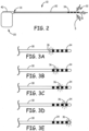
- FIG. 2 is a schematic diagram of an active medical device system 10 showing light 5 being emitted from a distal end 32 of the lead 30.
- the implanted active medical device 20 is illustrated as a neurostimulator, however, the implanted active medical device 20 can be any "active implantable medical device” or “implantable signal generator” as described above and can be placed in any location within a body cavity or tissue within the body, or on the surface of a patient's skin, as desired. This device can provide both electrical stimulation or sensing and optical stimulation therapy or optical stimulation therapy only.
- the active medical device 20 includes a housing defining a hermetic cavity.
- a hybrid or electronics and a power source or battery are located within the hermetic cavity.
- the electronics generally control the active medical device.
- the electronics includes memory.
- the memory can be any magnetic, electronic, or optical media, such as random access memory (RAM), read-only memory (ROM), electronically-erasable programmable ROM, flash memory, or the like.
- the power source can have a number of different sizes or capacities or configurations as required by different optical and/or electrical therapy indications.
- the power source can be electrically connected to the electronics and solid state light source via lead conductors extending along the length of the lead body 30.
- the power source can be any useful battery or inductive coil.
- the active medical device 20 can be coupled to a lead extension 22 having a proximal end 31 coupled to the active medical device 20, and a lead 30 having a proximal end 31 coupled to a distal end 32 of the lead extension 22 and a distal end 32 of the lead 30 coupled to one or more electrodes 34 and/or optical windows or light emissive segments 36 emitting light 5.
- the lead 30 proximal end 31 defines a lead connector and is coupled to a lead connector receptacle 40 of the active medical device 20, without a need for a lead extension 22.
- the active medical device 20 can be implanted in any useful region of the body such as in the abdomen of a patient 28, and the lead 30 is shown placed somewhere along the spinal cord 14 or in the upper body for brain stimulation.
- implantable medical device systems can also include a physician programmer and a patient programmer (not shown).
- the active medical device 20 can be considered to be an implantable signal generator of the type available from Medtronic, Inc. and capable of generating one or more optical and/or electrical signals occurring either simultaneously or one signal shifting in time with respect to the other, and having independently varying amplitudes and signal widths.
- the active medical device 20 contains a power source and the electronics for sending precise, electrical and/or optical signals to the patient to provide the desired treatment therapy.
- FIG.s 3A-3E are side elevation views of illustrative lead 30 distal ends illuminating light emission segments 36. These figures illustrate the selective illumination or light emission from one of the five individual light emission segments 36.
- the light emission segments 36 are separated by electrode 34 segments. There are five individual light emission segments 36 separated by four electrode 34 segments. Light can be selectively emitted from one or more of the individual light emission segments 36, as described below. Electricity can be selectively provided to one or more of the individual electrode 34 segments.
- the individual light emission segments 36 can be formed of any useful light transmissive material such as a glass or sapphire.
- the light emission segments 36 are preferably in the form of a ring or annular ring of light transmissive material.
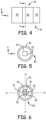
- FIG. 4 is a schematic diagram side elevation of a portion of an illustrative lead distal 30 end 32.
- FIG. 5 is a schematic cross-sectional view of an illustrative single solid state light source embodiment of FIG. 4 taken along line A-A.
- FIG. 6 is a schematic cross-sectional view of an illustrative multiple solid state light source embodiment of FIG. 4 taken along line A-A.
- FIG. 7 is a schematic cross-sectional view of an illustrative multiple solid state light source embodiment taken along a longitudinal axis of FIG. 4 . An x-y axis or x-z axis is illustrated on each figure to aid in orientation of the illustrated view.
- the distal end portion 32 includes a solid state light source 70 disposed within a light transmissive ring element 36.
- the light transmissive ring element 36 forming an exterior segment of the distal end portion 32.
- the light transmissive ring element 36 defines at least a portion of a hermetic cavity 33.
- the light transmissive ring element 36 can be hermetically sealed via brazing or diffusion bonding to the distal end 32 elements such as the electrode 34 segments.
- the solid state light source 70 can be any useful solids state light element.
- Solid state light elements include light emitting diodes (LEDs), organic light emitting diodes (OLEDs), laser diodes, vertical cavity surface emitting lasers (VCSELs) and polymer light emitting diodes, for example.
- the solid state light source 70 is optically coupled to the light transmissive ring element 36 to transmit light from the hermetic enclosure 33 and through the light transmissive ring element 36 and emit light into the environment surrounding the lead 30.
- an optically coupling fluid fills open space in the hermetic cavity 33 and substantially matches the index of refraction of the light transmissive ring element 36 and/or the solid state light source 70.
- the solid state light source 70 is spaced apart from the light transmissive ring element 36 by an air gap.
- the light transmissive ring element 36 can be hermetically bonded to an electrode 34 that can be described as an electrode ring element 34.
- the electrode ring element 34 forms an exterior segment of the distal end portion 32.
- the hermetic cavity 33 is further defined by an end cap 37 hermetically bonded to the electrode ring element 34 or light transmissive ring element 36.
- the end cap 37 can be formed of any useful metal or light transmissive material, as described herein.
- the electrode ring element 34 can be formed of any useful electrically conductive material and also form a hermetic barrier.
- the electrically conducting contact rings are formed of a metallic material such as, for example, titanium, stainless steel, MP35N, niobium, tantalum, platinum, and alloys or combinations thereof.
- the electrode ring element 34 is formed of a metallic material such as, for example, titanium.
- the element(s) and/or compounds used to form the light transmissive ring element 36 are selected in a manner to reduce tensile stresses with electrode ring elements 34.
- light transmissive ring element 36 employing glass, has a coefficient of thermal expansion (CTE) value about equivalent to or within 15% of the CTE associated with, electrode ring element 34.
- CTE coefficient of thermal expansion
- the lead distal end portion 32 includes a plurality of solid state light sources 70 and a plurality of light transmissive ring elements 36.
- each light transmissive ring element 36 surrounds one of the solid state light sources 70 forming a transmissive ring and light source pair.
- Each transmissive ring and light source pair is spaced apart for an adjacent transmissive ring and light source pair by an electrode ring element 34.
- the lead distal end portion 32 can include a plurality of transmissive ring and light source pairs and each transmissive ring and light source pair is activated independently of each other.
- FIG. 5 and FIG. 6 illustrate a transmissive ring and light source pair.
- a single light source 70 is disposed within the hermetic cavity at least partially defined by the light transmissive ring element 36. Only one or a single solid state light source 70 is disposed within a single light transmissive ring element 36 and the single solid state light source 70 emits light through an entire circumference of the single light transmissive ring element 36. The single solid state light source 70 transmits 360 degrees of light through the light transmissive ring element 36.
- a plurality or four light sources 70 are disposed within the hermetic cavity at least partially defined by the light transmissive ring element 36.
- Four solid state light sources 70 are disposed within a single light transmissive ring element 36 and the four solid state light sources 70 combine to emit light through an entire circumference of the single light transmissive ring element 36.
- the four solid state light sources 70 transmit 360 degrees of light through the light transmissive ring element 36.
- the four solid state light sources 70 are electrically coupled to an electronics element 38 that can include an integrated circuit or is electrically coupled to electronics or a circuit.
- the solid state light sources 70 can emit light primarily in different directions, such as a -x or +x or -y or +y directions.
- the solid state light sources 70 can be configured to be activated independently of each other. Thus, one solid state light sources 70 can be activated that emits light primarily in the +x direction while one or more of the remaining solid state light sources 70 remains non-activated, or one solid state light source 70 can be activated that emits light primarily in the -x direction while one or more of the remaining solid state light sources 70 remain non-activated, or one solid state light source 70 can be activated that emits light primarily in the -y direction while one or more of the remaining solid state light sources 70 remains non-activated, or one solid state light source 70 can be activated that emits light primarily in the +y direction while one or more of the remaining solid state light sources 70 remains non-activated.
- a plurality or two light sources 70 are disposed within the hermetic cavity at least partially defined by the light transmissive ring element 36.
- Two solid state light sources 70 are disposed in opposing directions and within a single light transmissive ring element 36 and the two solid state light sources 70 combine to emit light through an entire circumference of the single light transmissive ring element 36.
- the two solid state light sources 70 transmit 360 degrees of light through the light transmissive ring element 36.
- the two solid state light sources 70 are electrically coupled to an electronics element 38 that can include an integrated circuit or is electrically coupled to electronics or a circuit.
- the solid state light sources 70 can emit light primarily in different directions or opposing directions, such as a -x or +x directions.
- the solid state light sources 70 can be configured to be activated independently of each other. Thus, one solid state light source 70 can be activated that emits light primarily in the +x direction while remaining solid state light sources 70 remain non-activated, or one solid state light source 70 can be activated that emits light primarily in the -x direction while the remaining solid state light source 70 remains non-activated.
- the plurality of solid state light sources 70 is an array of at least ten solid state light sources 70.
- the array of at least ten solid state light sources 70 can be arranged on an annular element and co-axially disposed within the single light transmissive ring element 36. Further, any features described as part of one embodiment described herein can be used on or in conjunction with other embodiments described herein to yield yet a further embodiment. It is intended that the description also includes such modifications, variations and combinations.
Landscapes
- Health & Medical Sciences (AREA)
- Engineering & Computer Science (AREA)
- Biomedical Technology (AREA)
- Public Health (AREA)
- Nuclear Medicine, Radiotherapy & Molecular Imaging (AREA)
- Radiology & Medical Imaging (AREA)
- Life Sciences & Earth Sciences (AREA)
- Animal Behavior & Ethology (AREA)
- General Health & Medical Sciences (AREA)
- Veterinary Medicine (AREA)
- Pathology (AREA)
- Cardiology (AREA)
- Heart & Thoracic Surgery (AREA)
- Radiation-Therapy Devices (AREA)
- Electrotherapy Devices (AREA)
Claims (15)
- Système de dispositif médical actif implantable permettant de réaliser des techniques de stimulation optogénétique, le système comprenant :un dispositif médical actif (20) ;un fil conducteur (30) s'étendant entre une partie proximale couplée électriquement au dispositif médical actif et une partie d'extrémité distale configurée pour émettre de la lumière, la partie d'extrémité distale comprenant :une source de lumière à semi-conducteurs (70) disposée à l'intérieur d'un élément annulaire laissant passer la lumière (36),dans lequel l'élément annulaire laissant passer la lumière est lié hermétiquement à un élément annulaire d'électrode (34) et l'élément annulaire d'électrode formant un segment extérieur de la partie d'extrémité distale.
- Système de dispositif médical actif implantable selon la revendication 1, dans lequel la cavité hermétique est en outre définie par un capuchon d'extrémité (37) lié hermétiquement à l'élément annulaire d'électrode ou à l'élément annulaire laissant passer la lumière.
- Système de dispositif médical actif implantable selon l'une quelconque des revendications précédentes dans lequel la cavité hermétique est en outre définie par un capuchon d'extrémité (37) lié hermétiquement à l'élément annulaire laissant passer la lumière.
- Système de dispositif médical actif implantable selon l'une quelconque des revendications précédentes dans lequel la partie d'extrémité distale de fil conducteur comprend en outre une pluralité de sources de lumière à semi-conducteurs (70) et une pluralité d'éléments annulaires laissant passer la lumière (36), dans lequel chaque élément annulaire laissant passer la lumière entoure l'une des sources de lumière à semi-conducteurs formant une paire d'un anneau transmissif et d'une source de lumière, et chaque paire d'anneau transmissif et de source de lumière est espacée d'une paire adjacente d'anneau transmissif et de source de lumière par un élément annulaire d'électrode, en particulier dans lequel la partie d'extrémité distale de fil conducteur comprend une pluralité de paires d'anneaux transmissifs et de sources de lumière et chaque paire d'anneau transmissif et de source de lumière est activée indépendamment des autres.
- Système de dispositif médical actif implantable selon l'une quelconque des revendications 1 à 3 dans lequel une pluralité de sources de lumière à semi-conducteurs (70) est disposée à l'intérieur d'un élément annulaire laissant passer la lumière (36) unique.
- Système de dispositif médical actif implantable selon la revendication 5 dans lequel chaque source de la pluralité de sources de lumière à semi-conducteurs est activée indépendamment des autres.
- Système de dispositif médical actif implantable selon l'une quelconque des revendications 5 à 6 dans lequel la pluralité de sources de lumière à semi-conducteurs comprend deux sources de lumière à semi-conducteurs dirigeant la lumière dans des directions opposées, ou dans lequel la pluralité de sources de lumière à semi-conducteurs comprend quatre sources de lumière à semi-conducteurs dirigeant la lumière dans quatre directions différentes, ou dans lequel la pluralité de sources de lumière à semi-conducteurs comprend un réseau d'au moins dix sources de lumière à semi-conducteurs.
- Système de dispositif médical actif implantable selon l'une quelconque des revendications 1 à 3 dans lequel une source de lumière à semi-conducteurs (70) unique est disposée à l'intérieur d'un élément annulaire laissant passer la lumière (36) unique et la source de lumière à semi-conducteurs unique émet de la lumière à travers toute la circonférence de l'élément annulaire laissant passer la lumière unique.
- Système de dispositif médical actif implantable selon l'une quelconque des revendications précédentes dans lequel la source de lumière à semi-conducteurs émet de la lumière à travers toute la circonférence de l'élément annulaire laissant passer la lumière.
- Système de dispositif médical actif implantable selon l'une quelconque des revendications précédentes dans lequel la source de lumière à semi-conducteurs est une diode électroluminescente.
- Système de dispositif médical actif implantable selon l'une quelconque des revendications précédentes dans lequel l'élément annulaire laissant passer la lumière est le saphir.
- Système de dispositif médical actif implantable selon l'une quelconque des revendications précédentes dans lequel la source de lumière à semi-conducteurs est disposée complètement à l'intérieur de la cavité hermétique.
- Système de dispositif médical actif implantable selon la revendication 2 dans lequel la partie d'extrémité distale de fil conducteur comprend une pluralité d'anneaux transmissifs et d'éléments d'anneaux d'électrode alternés formant une surface extérieure de la partie d'extrémité distale et une source de lumière (70) est disposée à l'intérieur de chaque anneau transmissif et chaque source de lumière est activée indépendamment des autres.
- Système de dispositif médical actif implantable selon la revendication 13 dans lequel chaque élément annulaire laissant passer la lumière entoure deux sources de lumière à semi-conducteurs dirigeant la lumière dans des directions opposées, en particulier dans lequel chaque source de lumière est activée indépendamment des autres.
- Système de dispositif médical actif implantable selon l'une quelconque des revendications précédentes, dans lequel l'élément annulaire laissant passer la lumière forme un segment extérieur de la partie d'extrémité distale, en particulier dans lequel l'élément annulaire laissant passer la lumière définit au moins une partie d'une cavité hermétique (33).
Applications Claiming Priority (3)
| Application Number | Priority Date | Filing Date | Title |
|---|---|---|---|
| US201461984341P | 2014-04-25 | 2014-04-25 | |
| PCT/US2015/027228 WO2015164568A1 (fr) | 2014-04-25 | 2015-04-23 | Dispositif implantable comprenant un fil optique |
| EP15721451.1A EP3134173B1 (fr) | 2014-04-25 | 2015-04-23 | Dispositif implantable comprenant un fil optique |
Related Parent Applications (1)
| Application Number | Title | Priority Date | Filing Date |
|---|---|---|---|
| EP15721451.1A Division EP3134173B1 (fr) | 2014-04-25 | 2015-04-23 | Dispositif implantable comprenant un fil optique |
Publications (2)
| Publication Number | Publication Date |
|---|---|
| EP3378529A1 EP3378529A1 (fr) | 2018-09-26 |
| EP3378529B1 true EP3378529B1 (fr) | 2025-06-11 |
Family
ID=53059475
Family Applications (2)
| Application Number | Title | Priority Date | Filing Date |
|---|---|---|---|
| EP18161181.5A Active EP3378529B1 (fr) | 2014-04-25 | 2015-04-23 | Dispositif implantable comprenant un fil optique |
| EP15721451.1A Not-in-force EP3134173B1 (fr) | 2014-04-25 | 2015-04-23 | Dispositif implantable comprenant un fil optique |
Family Applications After (1)
| Application Number | Title | Priority Date | Filing Date |
|---|---|---|---|
| EP15721451.1A Not-in-force EP3134173B1 (fr) | 2014-04-25 | 2015-04-23 | Dispositif implantable comprenant un fil optique |
Country Status (3)
| Country | Link |
|---|---|
| US (2) | US10245441B2 (fr) |
| EP (2) | EP3378529B1 (fr) |
| WO (1) | WO2015164568A1 (fr) |
Families Citing this family (11)
| Publication number | Priority date | Publication date | Assignee | Title |
|---|---|---|---|---|
| EP3378529B1 (fr) * | 2014-04-25 | 2025-06-11 | Medtronic, Inc. | Dispositif implantable comprenant un fil optique |
| FR3045391B1 (fr) * | 2015-12-17 | 2019-09-06 | Commissariat A L'energie Atomique Et Aux Energies Alternatives | Dispositif implantable pour la stimulation optique du cerveau |
| US10335607B2 (en) | 2016-02-05 | 2019-07-02 | Boston Scientific Neuromodulation Corporation | Implantable optical stimulation lead and methods of making and using |
| US10625072B2 (en) * | 2016-10-21 | 2020-04-21 | Boston Scientific Neuromodulation Corporation | Electrical stimulation methods with optical observation and devices therefor |
| US11903683B2 (en) | 2018-08-03 | 2024-02-20 | Chelak Medical Solutions Inc | Non-barometric determination of hemodynamic effects of cardiac arrhythmias using signals sensed by an implantable device |
| EP3840824A1 (fr) | 2018-11-16 | 2021-06-30 | Boston Scientific Neuromodulation Corporation | Système de stimulation optique avec surveillance à la demande et procédés de fabrication |
| FR3104449B1 (fr) * | 2019-12-12 | 2021-12-24 | Commissariat Energie Atomique | Dispositif d'illumination implantable dans un être vivant |
| US12427332B2 (en) | 2021-04-08 | 2025-09-30 | Boston Scientific Neuromodulation Corporation | Photobiomodulation system and delivery device and methods of making and using |
| EP4515193A4 (fr) | 2022-04-29 | 2026-04-29 | Chelak Medical Solutions Inc | Systèmes, dispositifs et procédés de miniaturisation d'interrogation de réseau de bragg sur fibre pour intégration dans des dispositifs implantables |
| EP4565319A1 (fr) * | 2022-08-22 | 2025-06-11 | Boston Scientific Neuromodulation Corporation | Systèmes de photobiomodulation comprenant une électrode disposée sur ou tout prés un émetteur de lumière et procédés de fabrication et d'utilisation |
| EP4398258A3 (fr) | 2023-01-04 | 2024-08-28 | Boston Scientific Neuromodulation Corporation | Systèmes et procédés incorporant une interface utilisateur de photothérapie pour modulation optique |
Family Cites Families (21)
| Publication number | Priority date | Publication date | Assignee | Title |
|---|---|---|---|---|
| US5445608A (en) * | 1993-08-16 | 1995-08-29 | James C. Chen | Method and apparatus for providing light-activated therapy |
| US5556421A (en) | 1995-02-22 | 1996-09-17 | Intermedics, Inc. | Implantable medical device with enclosed physiological parameter sensors or telemetry link |
| US5902236A (en) | 1997-09-03 | 1999-05-11 | Pmt Corporation | Tissue electrode for recording and stimulation |
| US6198952B1 (en) | 1998-10-30 | 2001-03-06 | Medtronic, Inc. | Multiple lens oxygen sensor for medical electrical lead |
| US7395118B2 (en) * | 2003-09-25 | 2008-07-01 | Advanced Neuromodulation Systems, Inc. | System and method for implantable stimulation lead employing optical fibers |
| US7349618B2 (en) | 2006-04-26 | 2008-03-25 | Medtronic, Inc. | Optical feedthrough assembly for use in implantable medical device |
| US8290592B2 (en) | 2006-09-21 | 2012-10-16 | Cardiac Pacemakers, Inc. | Implantable medical device header with optical interface |
| US8288654B2 (en) | 2006-11-30 | 2012-10-16 | Medtronic, Inc. | Feedthrough assembly including a ferrule, an insulating structure and a glass |
| US7711428B2 (en) | 2007-01-18 | 2010-05-04 | Medtronic, Inc. | Hermetic lead connector assembly |
| US8131370B2 (en) * | 2007-01-18 | 2012-03-06 | Medtronic, Inc | Methods of manufacturing a hermetic lead connector |
| US20100280563A1 (en) * | 2007-02-28 | 2010-11-04 | Anne Norlin-Weissenrieder | Device and method for detecting and treating a myocardial infarction using photobiomodulation |
| US8538530B1 (en) | 2008-11-19 | 2013-09-17 | Advanced Bionics | Hermetically sealed feedthrough case |
| US8396570B2 (en) * | 2009-01-02 | 2013-03-12 | Cochlear Limited | Combined optical and electrical neural stimulation |
| US8192418B2 (en) | 2009-03-10 | 2012-06-05 | Medtronic, Inc. | Releasing a material within a medical device via an optical feedthrough |
| US9724784B2 (en) | 2009-03-10 | 2017-08-08 | Medtronic, Inc. | Optical feedthrough for medical devices |
| US20110125078A1 (en) | 2009-11-25 | 2011-05-26 | Medtronic, Inc. | Optical stimulation therapy |
| US9550063B2 (en) * | 2010-10-14 | 2017-01-24 | II Erich W. Wolf | Apparatus and method using near infrared reflectometry to reduce the effect of positional changes during spinal cord stimulation |
| EP2736594B1 (fr) | 2011-07-25 | 2016-09-14 | NeuroNexus Technologies, Inc. | Système de transfection pour neuromodulation avec administration de fluide passive |
| US9724524B2 (en) * | 2011-08-02 | 2017-08-08 | Medtronic, Inc. | Interconnection of conductor to feedthrough |
| WO2015164571A2 (fr) * | 2014-04-25 | 2015-10-29 | Medtronic, Inc. | Dispositif implantable doté d'un connecteur de sonde optique |
| EP3378529B1 (fr) * | 2014-04-25 | 2025-06-11 | Medtronic, Inc. | Dispositif implantable comprenant un fil optique |
-
2015
- 2015-04-23 EP EP18161181.5A patent/EP3378529B1/fr active Active
- 2015-04-23 EP EP15721451.1A patent/EP3134173B1/fr not_active Not-in-force
- 2015-04-23 WO PCT/US2015/027228 patent/WO2015164568A1/fr not_active Ceased
- 2015-04-23 US US14/694,134 patent/US10245441B2/en active Active
-
2019
- 2019-03-04 US US16/291,170 patent/US11110290B2/en active Active
Also Published As
| Publication number | Publication date |
|---|---|
| EP3378529A1 (fr) | 2018-09-26 |
| EP3134173A1 (fr) | 2017-03-01 |
| US20190201709A1 (en) | 2019-07-04 |
| US10245441B2 (en) | 2019-04-02 |
| WO2015164568A1 (fr) | 2015-10-29 |
| US20150306415A1 (en) | 2015-10-29 |
| US11110290B2 (en) | 2021-09-07 |
| EP3134173B1 (fr) | 2018-03-14 |
Similar Documents
| Publication | Publication Date | Title |
|---|---|---|
| US11110290B2 (en) | Implantable device with optical lead | |
| EP3134180B1 (fr) | Dispositif implantable doté d'un connecteur de sonde optique | |
| US8160696B2 (en) | Nerve stimulator and method using simultaneous electrical and optical signals | |
| US8936630B2 (en) | Optical stimulation therapy | |
| US9700736B2 (en) | Neuromodulation transfection system with active fluid delivery | |
| US10814140B2 (en) | Systems and methods for visualizing and controlling optogenetic stimulation using optical stimulation systems | |
| US7254443B2 (en) | Implantable medical device including a hermetic connector block extension | |
| US8652187B2 (en) | Cuff apparatus and method for optical and/or electrical nerve stimulation of peripheral nerves | |
| US8744570B2 (en) | Optical stimulation of the brainstem and/or midbrain, including auditory areas | |
| US20130317572A1 (en) | Low-level laser therapy | |
| US20130317573A1 (en) | Combination electrical stimulation and low-level laser therapy | |
| EP2736594B1 (fr) | Système de transfection pour neuromodulation avec administration de fluide passive | |
| EP2964321B1 (fr) | Système de neuromodulation distribuée avec des unités de commande d'enregistrement-stimulation auxiliaires | |
| JP2017521140A (ja) | 運動障害のための光遺伝学療法 | |
| US20230096373A1 (en) | Electrical optical medical lead |
Legal Events
| Date | Code | Title | Description |
|---|---|---|---|
| PUAI | Public reference made under article 153(3) epc to a published international application that has entered the european phase |
Free format text: ORIGINAL CODE: 0009012 |
|
| STAA | Information on the status of an ep patent application or granted ep patent |
Free format text: STATUS: THE APPLICATION HAS BEEN PUBLISHED |
|
| AC | Divisional application: reference to earlier application |
Ref document number: 3134173 Country of ref document: EP Kind code of ref document: P |
|
| AK | Designated contracting states |
Kind code of ref document: A1 Designated state(s): AL AT BE BG CH CY CZ DE DK EE ES FI FR GB GR HR HU IE IS IT LI LT LU LV MC MK MT NL NO PL PT RO RS SE SI SK SM TR |
|
| STAA | Information on the status of an ep patent application or granted ep patent |
Free format text: STATUS: REQUEST FOR EXAMINATION WAS MADE |
|
| 17P | Request for examination filed |
Effective date: 20190305 |
|
| RBV | Designated contracting states (corrected) |
Designated state(s): AL AT BE BG CH CY CZ DE DK EE ES FI FR GB GR HR HU IE IS IT LI LT LU LV MC MK MT NL NO PL PT RO RS SE SI SK SM TR |
|
| STAA | Information on the status of an ep patent application or granted ep patent |
Free format text: STATUS: EXAMINATION IS IN PROGRESS |
|
| 17Q | First examination report despatched |
Effective date: 20220426 |
|
| GRAP | Despatch of communication of intention to grant a patent |
Free format text: ORIGINAL CODE: EPIDOSNIGR1 |
|
| STAA | Information on the status of an ep patent application or granted ep patent |
Free format text: STATUS: GRANT OF PATENT IS INTENDED |
|
| INTG | Intention to grant announced |
Effective date: 20250107 |
|
| RAP3 | Party data changed (applicant data changed or rights of an application transferred) |
Owner name: MEDTRONIC, INC. |
|
| GRAS | Grant fee paid |
Free format text: ORIGINAL CODE: EPIDOSNIGR3 |
|
| GRAA | (expected) grant |
Free format text: ORIGINAL CODE: 0009210 |
|
| STAA | Information on the status of an ep patent application or granted ep patent |
Free format text: STATUS: THE PATENT HAS BEEN GRANTED |
|
| AC | Divisional application: reference to earlier application |
Ref document number: 3134173 Country of ref document: EP Kind code of ref document: P |
|
| AK | Designated contracting states |
Kind code of ref document: B1 Designated state(s): AL AT BE BG CH CY CZ DE DK EE ES FI FR GB GR HR HU IE IS IT LI LT LU LV MC MK MT NL NO PL PT RO RS SE SI SK SM TR |
|
| REG | Reference to a national code |
Ref country code: GB Ref legal event code: FG4D |
|
| REG | Reference to a national code |
Ref country code: CH Ref legal event code: EP |
|
| REG | Reference to a national code |
Ref country code: IE Ref legal event code: FG4D |
|
| REG | Reference to a national code |
Ref country code: DE Ref legal event code: R096 Ref document number: 602015091817 Country of ref document: DE |
|
| REG | Reference to a national code |
Ref country code: NL Ref legal event code: FP |
|
| PG25 | Lapsed in a contracting state [announced via postgrant information from national office to epo] |
Ref country code: ES Free format text: LAPSE BECAUSE OF FAILURE TO SUBMIT A TRANSLATION OF THE DESCRIPTION OR TO PAY THE FEE WITHIN THE PRESCRIBED TIME-LIMIT Effective date: 20250611 Ref country code: FI Free format text: LAPSE BECAUSE OF FAILURE TO SUBMIT A TRANSLATION OF THE DESCRIPTION OR TO PAY THE FEE WITHIN THE PRESCRIBED TIME-LIMIT Effective date: 20250611 |
|
| REG | Reference to a national code |
Ref country code: LT Ref legal event code: MG9D |
|
| PG25 | Lapsed in a contracting state [announced via postgrant information from national office to epo] |
Ref country code: GR Free format text: LAPSE BECAUSE OF FAILURE TO SUBMIT A TRANSLATION OF THE DESCRIPTION OR TO PAY THE FEE WITHIN THE PRESCRIBED TIME-LIMIT Effective date: 20250912 Ref country code: NO Free format text: LAPSE BECAUSE OF FAILURE TO SUBMIT A TRANSLATION OF THE DESCRIPTION OR TO PAY THE FEE WITHIN THE PRESCRIBED TIME-LIMIT Effective date: 20250911 |
|
| PG25 | Lapsed in a contracting state [announced via postgrant information from national office to epo] |
Ref country code: BG Free format text: LAPSE BECAUSE OF FAILURE TO SUBMIT A TRANSLATION OF THE DESCRIPTION OR TO PAY THE FEE WITHIN THE PRESCRIBED TIME-LIMIT Effective date: 20250611 |
|
| PG25 | Lapsed in a contracting state [announced via postgrant information from national office to epo] |
Ref country code: HR Free format text: LAPSE BECAUSE OF FAILURE TO SUBMIT A TRANSLATION OF THE DESCRIPTION OR TO PAY THE FEE WITHIN THE PRESCRIBED TIME-LIMIT Effective date: 20250611 |
|
| PG25 | Lapsed in a contracting state [announced via postgrant information from national office to epo] |
Ref country code: RS Free format text: LAPSE BECAUSE OF FAILURE TO SUBMIT A TRANSLATION OF THE DESCRIPTION OR TO PAY THE FEE WITHIN THE PRESCRIBED TIME-LIMIT Effective date: 20250911 |
|
| PG25 | Lapsed in a contracting state [announced via postgrant information from national office to epo] |
Ref country code: LV Free format text: LAPSE BECAUSE OF FAILURE TO SUBMIT A TRANSLATION OF THE DESCRIPTION OR TO PAY THE FEE WITHIN THE PRESCRIBED TIME-LIMIT Effective date: 20250611 |
|
| PG25 | Lapsed in a contracting state [announced via postgrant information from national office to epo] |
Ref country code: PT Free format text: LAPSE BECAUSE OF FAILURE TO SUBMIT A TRANSLATION OF THE DESCRIPTION OR TO PAY THE FEE WITHIN THE PRESCRIBED TIME-LIMIT Effective date: 20251013 |
|
| REG | Reference to a national code |
Ref country code: AT Ref legal event code: MK05 Ref document number: 1801899 Country of ref document: AT Kind code of ref document: T Effective date: 20250611 |
|
| PG25 | Lapsed in a contracting state [announced via postgrant information from national office to epo] |
Ref country code: IS Free format text: LAPSE BECAUSE OF FAILURE TO SUBMIT A TRANSLATION OF THE DESCRIPTION OR TO PAY THE FEE WITHIN THE PRESCRIBED TIME-LIMIT Effective date: 20251011 |
|
| PG25 | Lapsed in a contracting state [announced via postgrant information from national office to epo] |
Ref country code: AT Free format text: LAPSE BECAUSE OF FAILURE TO SUBMIT A TRANSLATION OF THE DESCRIPTION OR TO PAY THE FEE WITHIN THE PRESCRIBED TIME-LIMIT Effective date: 20250611 Ref country code: SM Free format text: LAPSE BECAUSE OF FAILURE TO SUBMIT A TRANSLATION OF THE DESCRIPTION OR TO PAY THE FEE WITHIN THE PRESCRIBED TIME-LIMIT Effective date: 20250611 |
|
| PG25 | Lapsed in a contracting state [announced via postgrant information from national office to epo] |
Ref country code: CZ Free format text: LAPSE BECAUSE OF FAILURE TO SUBMIT A TRANSLATION OF THE DESCRIPTION OR TO PAY THE FEE WITHIN THE PRESCRIBED TIME-LIMIT Effective date: 20250611 |
|
| PG25 | Lapsed in a contracting state [announced via postgrant information from national office to epo] |
Ref country code: PL Free format text: LAPSE BECAUSE OF FAILURE TO SUBMIT A TRANSLATION OF THE DESCRIPTION OR TO PAY THE FEE WITHIN THE PRESCRIBED TIME-LIMIT Effective date: 20250611 |
|
| PG25 | Lapsed in a contracting state [announced via postgrant information from national office to epo] |
Ref country code: EE Free format text: LAPSE BECAUSE OF FAILURE TO SUBMIT A TRANSLATION OF THE DESCRIPTION OR TO PAY THE FEE WITHIN THE PRESCRIBED TIME-LIMIT Effective date: 20250611 |
|
| PG25 | Lapsed in a contracting state [announced via postgrant information from national office to epo] |
Ref country code: SK Free format text: LAPSE BECAUSE OF FAILURE TO SUBMIT A TRANSLATION OF THE DESCRIPTION OR TO PAY THE FEE WITHIN THE PRESCRIBED TIME-LIMIT Effective date: 20250611 Ref country code: RO Free format text: LAPSE BECAUSE OF FAILURE TO SUBMIT A TRANSLATION OF THE DESCRIPTION OR TO PAY THE FEE WITHIN THE PRESCRIBED TIME-LIMIT Effective date: 20250611 |
|
| PG25 | Lapsed in a contracting state [announced via postgrant information from national office to epo] |
Ref country code: DK Free format text: LAPSE BECAUSE OF FAILURE TO SUBMIT A TRANSLATION OF THE DESCRIPTION OR TO PAY THE FEE WITHIN THE PRESCRIBED TIME-LIMIT Effective date: 20250611 |
|
| PG25 | Lapsed in a contracting state [announced via postgrant information from national office to epo] |
Ref country code: IT Free format text: LAPSE BECAUSE OF FAILURE TO SUBMIT A TRANSLATION OF THE DESCRIPTION OR TO PAY THE FEE WITHIN THE PRESCRIBED TIME-LIMIT Effective date: 20250611 |
|
| PGFP | Annual fee paid to national office [announced via postgrant information from national office to epo] |
Ref country code: NL Payment date: 20260319 Year of fee payment: 12 |
|
| PLBE | No opposition filed within time limit |
Free format text: ORIGINAL CODE: 0009261 |
|
| STAA | Information on the status of an ep patent application or granted ep patent |
Free format text: STATUS: NO OPPOSITION FILED WITHIN TIME LIMIT |
|
| REG | Reference to a national code |
Ref country code: CH Ref legal event code: L10 Free format text: ST27 STATUS EVENT CODE: U-0-0-L10-L00 (AS PROVIDED BY THE NATIONAL OFFICE) Effective date: 20260423 |