EP3378554A1 - Pied modulaire, procédé et dispositif de filtration d'un fluide brut contenant une impureté au moyen d'au moins une unité de filtre à membrane ainsi que leur utilisation - Google Patents
Pied modulaire, procédé et dispositif de filtration d'un fluide brut contenant une impureté au moyen d'au moins une unité de filtre à membrane ainsi que leur utilisation Download PDFInfo
- Publication number
- EP3378554A1 EP3378554A1 EP18163518.6A EP18163518A EP3378554A1 EP 3378554 A1 EP3378554 A1 EP 3378554A1 EP 18163518 A EP18163518 A EP 18163518A EP 3378554 A1 EP3378554 A1 EP 3378554A1
- Authority
- EP
- European Patent Office
- Prior art keywords
- membrane filter
- fluid
- filter unit
- compressed air
- raw
- Prior art date
- Legal status (The legal status is an assumption and is not a legal conclusion. Google has not performed a legal analysis and makes no representation as to the accuracy of the status listed.)
- Granted
Links
Images
Classifications
-
- C—CHEMISTRY; METALLURGY
- C02—TREATMENT OF WATER, WASTE WATER, SEWAGE, OR SLUDGE
- C02F—TREATMENT OF WATER, WASTE WATER, SEWAGE, OR SLUDGE
- C02F1/00—Treatment of water, waste water, or sewage
- C02F1/44—Treatment of water, waste water, or sewage by dialysis, osmosis or reverse osmosis
-
- B—PERFORMING OPERATIONS; TRANSPORTING
- B01—PHYSICAL OR CHEMICAL PROCESSES OR APPARATUS IN GENERAL
- B01D—SEPARATION
- B01D61/00—Processes of separation using semi-permeable membranes, e.g. dialysis, osmosis or ultrafiltration; Apparatus, accessories or auxiliary operations specially adapted therefor
- B01D61/14—Ultrafiltration; Microfiltration
- B01D61/18—Apparatus therefor
-
- B—PERFORMING OPERATIONS; TRANSPORTING
- B01—PHYSICAL OR CHEMICAL PROCESSES OR APPARATUS IN GENERAL
- B01D—SEPARATION
- B01D61/00—Processes of separation using semi-permeable membranes, e.g. dialysis, osmosis or ultrafiltration; Apparatus, accessories or auxiliary operations specially adapted therefor
- B01D61/14—Ultrafiltration; Microfiltration
- B01D61/20—Accessories; Auxiliary operations
-
- B—PERFORMING OPERATIONS; TRANSPORTING
- B01—PHYSICAL OR CHEMICAL PROCESSES OR APPARATUS IN GENERAL
- B01D—SEPARATION
- B01D63/00—Apparatus in general for separation processes using semi-permeable membranes
- B01D63/08—Flat membrane modules
- B01D63/087—Single membrane modules
-
- B—PERFORMING OPERATIONS; TRANSPORTING
- B01—PHYSICAL OR CHEMICAL PROCESSES OR APPARATUS IN GENERAL
- B01D—SEPARATION
- B01D65/00—Accessories or auxiliary operations, in general, for separation processes or apparatus using semi-permeable membranes
- B01D65/02—Membrane cleaning or sterilisation ; Membrane regeneration
-
- B—PERFORMING OPERATIONS; TRANSPORTING
- B01—PHYSICAL OR CHEMICAL PROCESSES OR APPARATUS IN GENERAL
- B01D—SEPARATION
- B01D2313/00—Details relating to membrane modules or apparatus
- B01D2313/21—Specific headers, end caps
-
- B—PERFORMING OPERATIONS; TRANSPORTING
- B01—PHYSICAL OR CHEMICAL PROCESSES OR APPARATUS IN GENERAL
- B01D—SEPARATION
- B01D2313/00—Details relating to membrane modules or apparatus
- B01D2313/26—Specific gas distributors or gas intakes
-
- B—PERFORMING OPERATIONS; TRANSPORTING
- B01—PHYSICAL OR CHEMICAL PROCESSES OR APPARATUS IN GENERAL
- B01D—SEPARATION
- B01D2321/00—Details relating to membrane cleaning, regeneration, sterilization or to the prevention of fouling
- B01D2321/04—Backflushing
-
- B—PERFORMING OPERATIONS; TRANSPORTING
- B01—PHYSICAL OR CHEMICAL PROCESSES OR APPARATUS IN GENERAL
- B01D—SEPARATION
- B01D2321/00—Details relating to membrane cleaning, regeneration, sterilization or to the prevention of fouling
- B01D2321/18—Use of gases
- B01D2321/185—Aeration
Definitions
- the invention relates to a module foot for a device for filtering raw fluid by means of at least one membrane filter unit, with at least one compressed air area with at least one compressed air inlet and at least one raw water area with at least one raw water inlet according to the preamble of claim 1.
- the invention relates to a device for filtering raw fluid by means of at least one membrane filter unit according to the preamble of claim 6.
- the invention also relates to a method for filtering a crude fluid containing a contamination by means of at least one membrane filter unit, according to claim 1.
- the invention relates to the use of a module base in a filter device for pearly feeding compressed air according to claim 10.
- Filtering methods and filter devices are generally known from the prior art.
- membrane filters For filtering raw water, such as spring water, filter systems are used with membrane filters in which the raw water is pumped by means of a pump through membrane filter elements.
- a membrane filter elements can tubular membranes made of various materials, the wall thickness z. B. 0.1 to 1.0 mm and more.
- the raw water is freed of suspended particles and dirt particles as well as viruses and bacteria and the like, which are deposited on the surface of the membranes.
- To clean the membranes is then carried out at regular intervals a backwashing in the way that in conventional filter systems by means of an additional backwash the membrane elements are treated with pure water opposite to the direction of filtration.
- the deposited dirt particles are detached at the membrane elements and can be discharged via a sewer pipe.
- a method and a filter system for filtering raw water and for backwashing membrane filter units wherein at least two membrane filter units are used with which pure water is produced in the filtering operation of polluted raw water, wherein in the backwash for cleaning the membrane filter elements this opposite to the filtration direction with be used as rinse water used pure water.
- Raw water is supplied via a pump to at least one membrane filter unit operating in the filtering mode, wherein the pure water produced by at least one membrane filter unit is introduced in the backwashing direction into the membrane filter unit to be backwashed and then discharged on the output side as rinsing waste water.
- module foot according to claim 1 an apparatus according to claim 6, a method according to claim 7 and a use according to claim 10.
- the invention includes the technical teaching that in a module base for a device for filtering raw fluid by means of at least one membrane filter unit, with at least one compressed air area with at least one compressed air inlet and at least one raw water area with at least one raw water inlet, provided that the raw water area and the compressed air area are separated by a partition, wherein the partition is at least partially formed with at least one bead holes as an aerator, so that supplied compressed air from the compressed air area by the partition in the raw water area pearls.
- the partition is preferably made of a metal sheet. This is preferably slightly curved, thus concave or convex. Other embodiments are possible.
- the partition wall is preferably formed as a circular disk.
- the wall thickness of the partition wall is preferably constant. In other embodiments, the wall thickness of the partition varies.
- the bead opening is designed such that incoming compressed air bubbles. That is, the partition creates small bubbles or droplets of the incoming compressed air.
- the module foot has a cup-shaped housing having a bottom and a side wall, wherein the partition wall is arranged at a distance from the bottom area in the housing.
- the compressed air area is smaller than the raw water area. That is, the partition sits off-center.
- the partition wall preferably separates the two areas approximately parallel to the floor. The partition extends in each case to the adjacent side wall, so that the areas are separated or separated by the partition wall.
- a further embodiment provides that the compressed air inlet is formed as a passage opening through the side wall in a region between the bottom and the partition wall. Compressed air thus passes through the compressed air inlet only in the compressed air area and has to pass to the membrane filter unit, the partition, more precisely, their passage openings. As a result, the beads of compressed air is realized.
- an embodiment provides that the partition has a plurality of perforations. Preferably, several perforations are provided.
- the bead openings can be distributed as desired over the partition wall.
- a targeted distribution of the perforations is provided in order to achieve a homogeneous distribution of the pearling compressed air.
- an embodiment provides that the bead openings are arranged in an annular pattern in which a central region of the partition wall has fewer bead openings than an outer zone in the sidewall direction.
- an outer annular region that is to say the region adjacent to the side wall, has fewer bead openings.
- the bead openings are provided exclusively in a middle ring arrangement. The middle area and the outer ring area are free of perforations.
- the invention also includes the technical teaching that in a device for filtering raw fluid by means of at least one membrane filter unit, wherein the device comprises a filter stage with at least one membrane filter unit which is fluidically connected to a Rohfluidseite with a Rohfluidzu Entry and which is formed in one Filtering operation to promote raw fluid in the filter direction through the membrane filter unit so as to produce pure fluid on a clean fluid side, and which is fluidly connected on the clean fluid side with a Spülfluidzu Entry and which is adapted to promote in a backwash rinse fluid in a backwash direction through the membrane filter unit to the Membrane filter unit of filtered dirt particles to clean, further comprising a supply for supplying shear force increasing means, in particular a compressed air supply, is provided, which is designed to e shear in the backwash operation increasing means Inzublasen, it is provided that at least one module foot according to one of the preceding claims is provided, wherein the supply of shear force increasing means is effected by the module foot.
- the shear force increasing means are preferably designed as compressed air. This flows into the module foot and penetrates through the through openings of the partition. In this way, a bead of compressed air is generated.
- a partition a plurality of partitions may be provided.
- the partitions may have the same passage opening arrangement. In other Embodiments, the partitions have differently arranged passage openings.
- the invention includes the technical teaching that in a method of filtering a raw fluid containing a contaminant by means of at least one membrane filter unit, wherein in a filter operation the dirty raw fluid is conveyed from a raw fluid side in a filtering direction through the membrane filter unit to a clean fluid side the clean fluid side to produce a clean purified substantially of contaminants, and in a backwash operation, a purge fluid is conveyed in a backwash direction through the membrane filter unit to clean the membrane filter unit of the filtered contamination, it is provided that shear force increasing means by a Modulfuß the membrane filter unit described here be supplied. In the backwash mode, the compressed air, which represents the shear force increasing agent, supports the cleaning process of the membranes.
- the supplied compressed air is bubbled in the backwash by the module base, that is, it form small bubbles of compressed air or drops. These enter the membrane and rise in this. By rising, the pearling compressed air causes a shearing force effect on adhering dirt particles. These are then peeled off and driven upwards with the flushing fluid and the compressed air to the module head. From there, the dirt is discharged accordingly.
- a rinse water is rinsed from the outside through the membrane filter unit in the backwash direction and purge air designed as compressed air is supplied to the membrane filter unit in a beaded manner by the module foot.
- the supplied pearlescent compressed air increases through membrane openings and / or capillaries of the membrane filter unit in the direction of the module head and thereby shears off adhering dirt in the membrane filter unit, and then collects with the rinsing water in the module head.
- the separating wall acting as a perforator causes a uniform distribution of the incoming compressed air. The targeted distribution of the compressed air, an improved cleaning of the membrane filter units is effected.
- the invention includes the technical teaching that a use of a module base is provided in a filter device for pearly supplying compressed air. It has surprisingly been found that a pearling supply of compressed air provides improved rinsing results. By the pearling supply through the module foot can be the beads adjust the supplied compressed air. By choosing a suitable passage opening and its arrangement, improved dishwashing results can be achieved.
- a filter operation in a filter operation the dirty raw fluid is conveyed from a raw fluid side in a filter direction through the membrane filter unit to a clean fluid side so as to be transported on the Pure fluid side to produce a clean purified from contaminants substantially pure fluid, and in a backwashing a rinse fluid is conveyed in a backwash direction through the membrane filter unit to clean the membrane filter unit of the filtered contamination
- an additional filter means the raw fluid on the Rohfluidseite is added to improve the filtering and / or wherein in the backwashing additionally shear force increasing means, in particular compressed air, is blown into the membrane filter unit to the backwashing in the membrane purity of the contamination and the additional filter medium to clean.
- the crude fluid in addition to an undesired contamination in one embodiment, also comprises an additional filter medium, which thus represents a deliberate contamination.
- the additional filter means is dispensed with.
- the crude fluid is thus in one embodiment a combination of a clean fluid, which is the final product of the filtering process, with an unwanted pollution and a wanted pollution, so a total of pure fluid plus pollution.
- the intentional contamination is not provided. In order to separate the raw fluid from the unwanted contamination, in one embodiment the intentional contamination is added. The intentional contamination is thus matched to the unwanted contamination and supports the filtering process.
- the crude fluid is preferably a raw liquid, more precisely a raw water.
- the pure fluid is preferably a pure liquid, more precisely a pure water.
- the - wanted and / or unwanted - pollution is a fluid, but may also be present in particulate form - detachable or insoluble - in the raw fluid.
- the desired contamination ie the additional filter medium, is completely dispensed with.
- the raw fluid is supplied to the membrane filter unit on the raw fluid side.
- the raw fluid filtered to the clean fluid is removed on the clean fluid side of the membrane filter unit.
- the contamination remains in filter operation in the membrane filter unit.
- the contamination of the clean fluid to the crude fluid is preferably carried out at different times.
- the pure fluid is only polluted with the unwanted pollution. This is combined in time with the desired pollution.
- the crude fluid thus produced is fed via a conveyor unit, preferably a pump, the membrane filter unit.
- the pressure at which the crude fluid is fed to the membrane filter unit can be selected as desired.
- the crude fluid is contaminated clean fluid without intentional contamination.
- the membrane filter unit filters the contamination out of the raw fluid.
- the cleaning is carried out both in the case where an intentional contamination is added, as well as in the case where the intentional pollution is dispensed with, the same.
- the membrane filter unit must be cleaned with appropriate contamination. This is done by means of backwashing.
- a (back) flushing fluid is conveyed into a flushing direction into the membrane filter unit.
- the rinsing direction is opposite to the filter direction.
- the flushing fluid may be any fluid suitable for cleaning the membrane filter unit.
- the flushing fluid is preferably in the form of a pure fluid, preferably in liquid form, in particular as pure water.
- a shear rate increasing agent is supplied to the membrane filter unit in addition to the pure fluid.
- compressed air is used as the shear force increasing means.
- shorter compressed air is used in the following instead of shear force increasing means, whereby other shear force increasing means, in particular gaseous or fluid shear force increasing means can be used.
- the supply of compressed air takes place from the raw water side, more precisely via the module foot.
- the guided through the module foot compressed air forms when passing through the partition beads, so small drops or bubbles. Accordingly, the passage openings are sized.
- the through holes have a diameter range in the order of 0.1 mm to a few millimeters.
- the compressed air acts in the filter direction and the flushing fluid is opposite in the flushing direction.
- the pressure of the flushing fluid and the compressed air are matched to one another.
- the ratio of purge fluid pressure to compressed air pressure is at least about 25:75, preferably about 50:50.
- the compressed air is supplied bubbly. This is achieved via the module foot, through which the compressed air is supplied.
- the additional contamination of the raw fluid in one embodiment with intentional contamination, the additional filter means requires tuning of the pressures.
- the contamination dissolved by the membrane filter unit is mixed with the flushing fluid and the compressed air via a corresponding discharge from the membrane filter unit dissipated.
- This removal of the now contaminated flushing fluid takes place on a discharge side.
- the flushing fluid that was once unpolluted for cleaning now includes the filtered intentional and unwanted contamination.
- additional, intentional soiling it is added to the side where the compressed air is already bubbling. In this way it is prevented that the additional contamination adds the partition with the through holes. Due to the improved results with acting as a perlator Modulfuß but can be completely dispensed with the additional pollution.
- the compressed air also causes an anti-gravity flooding of the pollution, so that it can be easily removed at an upper end of the membrane filter unit - more precisely on a module head - from this.
- the rest of the membrane filter unit thus remains surrounded or surrounded by the hardly or hardly contaminated flushing fluid.
- the filtering process can be carried out in parallel by means of several filter devices.
- the filter methods can be executed offset in time, so that is filtered in one operation and is backwashed in the parallel process.
- the operations may be coupled such that clean fluid from the one process is diverted during filtering to perform backwashing in the parallel process.
- activated carbon is added as an additional filter medium.
- Activated carbon is particularly suitable for filtering chemical contaminants.
- the contamination adheres to the activated carbon and remains in the membrane filter unit. But it can also use other adapted to the unwanted pollution filter media.
- the filter medium is supplied in powder form. In this way, the effective surface of the filter medium is optimized for improved filtering.
- the addition of pulverulent activated carbon is particularly preferred.
- the filter medium or the contamination or the contamination and the filter medium can penetrate into pores of the membrane filter elements used in the membrane filter unit.
- a preferred embodiment of the present invention provides that a granule or particle size of the powdered filter medium is dimensioned such that these in the pores the membrane filter elements can penetrate. Due to a smaller grain size, an effective surface of the added amount of filter medium is optimized. Larger grain sizes cause predominant adhesion to the outside of the membrane filter elements. The smaller granule sizes cause at least partial penetration into the membrane pores. This clogging requires an improved backwashing process. With conventional backwashing operations, such a small grain size is not possible because the clogging of the membrane pores can not be reversed sufficiently by backwashing. Therefore, according to the invention, the shear force increasing means, preferably in the form of compressed air, are supplied during backwashing.
- the pressure of flushing fluid and compressed air is matched to one another.
- the grain size and the membrane pore size are coordinated.
- the contamination together with the additional filter medium with the flushing fluid and / or the shear force increasing means or the compressed air from the membrane filter unit are conveyed into at least one further filter stage and filtered there, so that pure water is produced there again.
- a multi-stage filtering process can be realized, in which the present in the flushed, dirty detergent activated carbon or generally filter means, the effect of which is available for multiple filtering operations, can continue to be used.
- the contamination including flushing fluid and / or shear rate increasing agent is collected and removed by suitable means.
- a corresponding collecting vessel is preferably provided.
- the shear force increasing means in particular the compressed air causes in the flushing fluid an upgrade, so moving against gravity, the pollution. Accordingly, the contamination is collected at an upper end of the membrane filter unit to be purged.
- a discharge line is attached, which can be blocked via corresponding actuators, more precisely via valves.
- the corresponding actuators are opened and the contamination removed.
- the contaminated flushing fluid is removed to another filter stage.
- the further filter stage is constructed analogously to the first filter stage.
- the polluted flushing fluid is fed analogously to the raw water in the first filter stage via a feed line to a membrane filter unit or a plurality of membrane filter units, optionally with the addition of activated carbon.
- the supply of activated carbon or another filter medium can be reduced because the contaminant flushing fluid already contains the additional filter medium.
- the contaminated flushing fluid is through the membrane filter unit (s) promoted and obtained on the clean fluid side of contaminated pure water in the filter operation.
- the second filter stage can also be switched from a filter mode to a backwash mode. In the backwashing operation, a flushing fluid is conveyed counter to the filter direction, thus in the backwashing direction, through the membrane filter unit (s), analogously to the first filter stage.
- the flushing fluid used may be the pure water produced in one of the filter stages or a separately supplied or generated flushing fluid. Depending on whether additional filter stages, which are constructed in an analogous manner, are provided, corresponding filter operations follow.
- the filtering and backwashing is carried out in the at least one further filter stage as in the first filter stage. It can be arranged in this way any number of filter stages.
- the recovered pure fluid and / or flushing fluid can be fluidly connected via corresponding lines with flushing fluid and / or pure water of different filter stages.
- the raw fluid and / or the contaminated flushing fluid can be fluidically connected to the raw fluid and / or the contaminated flushing fluid of other filter stages via corresponding conduit systems. Control is the coupling of flushing / clean / raw fluid via respective actuators such as valves, pumps and the like.
- the contamination resulting in a further filter stage including additional filter medium together with flushing fluid and shear rate increasing agent, in particular compressed air, are sedimented in a sedimentation tank, so that a sediment slurry is formed.
- the sedimentation takes place in a last filter stage, but can also be carried out in intermediate filter stages.
- the contaminated flushing fluid is pumped into one or more sedimentation tanks. There, the contaminated flushing fluid is calmed so that the contaminant can settle in the sedimentation tank.
- the settled impurity forms a sediment sludge.
- the sediment sludge is removed from the sedimentation tank by suitable means.
- the discharged sediment sludge can now be used in many ways.
- the sediment sludge can be fed, for example, to the raw water of a front filter stage.
- the activated carbon contained in the sediment slurry or the additional filter medium contained therein can thus be used in a front filter stage. This is particularly conducive because even in the sediment filter stage, the activated carbon has not completely lost its filtering effect and so this effect can continue to use. In this way, an environmentally friendly filter cycle can be realized.
- a preferred embodiment provides that the sediment sludge is supplied to the raw fluid of a front filter stage.
- the feeding of sediment sludge, crude fluid, flushing fluid, additional filter medium and / or shear force increasing agents takes place under predetermined parameters, such as quantity ratio, pressure ratio and / or temperature conditions.
- the feed preferably takes place under predefined quantities and / or pressure ratios which are correspondingly coordinated with one another.
- a device for filtering raw fluid by means of at least one membrane filter unit has means for carrying out a method described above, in particular a filter stage with at least one membrane filter unit, which fluidly connects to a raw fluid side with a raw fluid supply and is adapted to promote in a filtering operation raw fluid in the filter direction through the membrane filter unit so as to produce pure fluid on a clean fluid side, and which is fluidly connected to the clean fluid side with a Spülfluidzu Insert and which is formed in a backwash operation rinse fluid in a backwash direction through the membrane filter unit to clean the membrane filter unit of filtered dirt particles, further comprising a supply for supplying shear force increasing means, in particular a compressed air supply is provided which is designed to inject shear rate increasing agent in the backwash mode.
- a Modulfuß is provided for suitable control of the supplied compressed air.
- a central supply adapted to add additional filtering agent to the raw fluid in the filtering operation to improve filter
- the membrane filter unit has at least one membrane filter element with membrane pores through which the crude fluid is conveyed and in whose membrane pores or at the membrane surfaces dirt particles accumulate.
- raw fluid and an additional filter medium are added on the raw fluid side in the filter operation in order to filter them through the To promote membrane filter unit, in particular activated carbon is added as an additional filter means.
- Yet another embodiment provides that a plurality of mutually coupled filter stages are provided, whose corresponding clean fluid sides and / or Rohfluidrete are at least partially coupled or coupled together.
- Last but not least, another embodiment provides that a use of a pulverulent activated carbon in the crude fluid in an apparatus and / or a method for filtering raw fluid by means of at least one membrane filter unit having at least one membrane element with membrane pores, through which the raw fluid is conveyed for filtering, wherein the membrane filter units by means of backwashing by supplying shear force increasing means, in particular compressed air is cleaned, is provided.
- the shear force increasing means is preferably gaseous and most preferably formed as compressed air.
- the compressed air at least during injection, has a pressure which is preferably in a range of approximately greater than or equal to 0.2 bar to approximately less than or equal to 2.0 bar, for example approximately 0.5 bar, approximately 1.0 bar and more preferably approximately zero 1.5 bar, most preferably less than or equal to 2.5 bar.
- the compressed air is supplied via the serving as a perlator Modulfuß.
- An additional filter medium which can be added in one embodiment, is preferably formed as activated carbon and / or as a powder.
- the additional filter medium is formed as activated carbon and / or as a powder having a grain size which is designed such that the powder grains or the activated carbon can penetrate into membrane pores of the membrane filter unit.
- the additional filter means is formed as powdered activated carbon.
- the device which is designed in particular as a filter system, comprises a membrane filter unit.
- the device preferably has at least two membrane filter units.
- the membrane filter units can be arranged in a filter stage or in different filter stages. In this case, the membrane units may be identical. In another embodiment, the membrane filter units are formed differently. In particular, membrane filter units are designed differently in different filter stages.
- raw water is pumped as a raw fluid through the membrane filter units, while at least one of the membrane filter units is decoupled from the filtration operation in the backwashing operation. In one embodiment, a separate supply of flushing fluid intended.
- This uncoupled membrane filter unit, the pure water produced by the other or the other membrane filter units is supplied as flushing fluid in the backwash direction, so that the dirt particles or contamination can be detached at the membrane filter elements and discharged via a sewer line.
- No additional backwash pump is needed in the embodiment.
- the backwashing is done via a separate backwash pump.
- a backwashing of individual membrane filter units can be carried out one after the other without interruption of the filtration operation with this method, thus in a quasi-continuous process. It is particularly advantageous to assist in the backwashing process by blowing in compressed air on the raw fluid side or the raw water side, the detachment of the dirt particles to the individual membrane filter elements.
- an additional filter means such as powdered activated carbon support is conducive.
- an additional filter means such as powdered activated carbon support is conducive.
- the injection of compressed air - even in filtration mode - is very advantageous, as this too fast fouling of the membrane filter elements can be prevented.
- the blowing of the shear force increasing means in particular of compressed air, takes place exclusively in the backwashing operation.
- the injected compressed air dirt deposits are more easily solved and also detached from the membrane filter elements and can collect in an upper chamber of the membrane filter elements, from where they can then be discharged during the backwashing via the sewer.
- the filter system comprises at least two membrane filter units, which allows a filtering operation and a backwash operation with only a single pump, in other embodiments with multiple pumps.
- the pure water produced by one or more other membrane filter units is used as flushing fluid, more specifically as flushing water, in which this flushing water is introduced in the backwash direction into the membrane filter unit to be flushed back.
- appropriate shut-off valves are provided.
- the feed lines leading to the membrane filter units from the pump or pumps have separate shut-off valves and also the drain lines leading from the membrane filter units to the sewer line each have separate shut-off valves.
- the pure water produced in the filter system for backwashing individual membrane filter units.
- compressed air can be blown into the membrane filter units via separate compressed air lines in the region of the raw water supply or the raw water side, resulting in at least Backwashing in a very advantageous manner results in a detachment of dirt particles on the membrane filter elements.
- the membrane filter elements of the membrane filter units can be tubular or other shaped elements which can be flowed through from inside to outside or vice versa in the filtration process. In this case, the membrane filter elements can be used for example in cylindrical, vertically oriented pressure vessels that form the membrane filter units of the filter system.
- Drain lines can be connected via shut-off valves with a common sewer pipe for discharging the backwashed rinse water. This upper chamber with the membrane filter units can be vented via an automatic vent valve.
- the filtering process takes place according to the so-called IN / OUT principle. It is filtered from the inside to the outside. Accordingly, powdered activated carbon is added to the raw water or crude fluid before a raw water pump, feed pump or feed pump. Afterwards, the mixed medium, ie raw water plus activated carbon, hits the membrane of the membrane filter unit, ie the filter unit of the first filter stage. In the filtration process preferably no compressed air or another shear rate increasing agent is added. In the backflush mode, i. During backwashing, the previously treated water (filtrate, pure water or generally pure fluid) is used for backwashing as flushing fluid or rinsing water.
- the use of the produced pure water has the advantage that what pure water once went through in the filtering direction through the membrane filter unit, this goes easily in the opposite direction, i. in the backwash direction, also back through the membrane filter unit.
- air is blown into a lower area of the membrane filter unit, more precisely at the bottom of the membrane in the module base air, more precisely compressed air, and from outside to inside (OUT / IN), the rinsing or pure water (filtrate) in pushed in the membrane unit.
- the compressed air generates a shearing effect in the area of the membrane elements on the pollution and solves the pollution easier from the membrane filter unit.
- the dirt removed by the air and the backwash water rises together upwards, thus against the force of gravity, into a module head. From there, the contaminated flushing fluid is removed, preferably discharged laterally. Air is preferably used only in the backwashing and is blown down into the membrane, more precisely in the module base.
- the device for filtering for the IN / OUT method ie from the inside out, and for a backwash after the OUT / IN method, that is from the outside in, designed.
- the tube fluid is filtered from the inside to the outside.
- the device has a module footing. This is among others designed for the introduction of scavenging air and / or raw water.
- a module housing is provided in fluid communication with the module base . This is designed as a hollow cylinder.
- the Membranfilterelmente are arranged such that raw water or crude fluid is introduced from the module base in the membrane filter elements.
- the membrane filter elements are approximately tubular in shape.
- the crude fluid is introduced during the filtration of the module base exclusively in the membrane filter elements. From there, the raw fluid pushes through the pores to the outside. The contaminant will adhere to the inside of the membrane filter elements and / or to the inside of the pores.
- the purified crude fluid pushes through the pores to the outside.
- a filter medium such as activated carbon
- this is also moved through the module base in the filter elements with the crude fluid.
- the filter medium adheres to the inside of the membrane filter elements and / or to the inside of the pores, as well as the contamination.
- the module foot has a raw water inlet and a scavenging air inlet. Both lead to a common chamber of the module base.
- the raw fluid passes through a perforated partition to the filter elements.
- the partition wall is perforated, for example, such that the passage realized by the perforation leads into the filter elements, more precisely the cavity of the filter elements. Since the chamber is suitable both for the raw fluid and for scavenging air, the same applies to the scavenging air.
- the partition fluidly connects the chamber to the interior of the filter elements or membrane filter elements. After passing through the pores of the membrane filter elements, the cleaned crude fluid enters the interior of the hollow cylindrical module housing, in which the membrane filter unit is arranged. Via a clean water outlet, the purified fluid comes out of the interior.
- the rinsing wastewater is discharged from the membrane filter elements via corresponding Spülabwassertechnischen.
- the membrane filter units are fluidically connected to a module head. This has passages to the cavity of the membrane filter elements, so that the rinsing wastewater passes through the passages from the cavity to the Spülabwassertechnisch.
- the membrane filter elements are preferably designed as capillaries. Due to the capillary action, the raw fluid pushes through the pores. More specifically, the capillaries are formed as capillary molded with synthetic resin. The capillaries are potted at their ends with synthetic resin. In this area, raw fluid does not get out through the pores. Due to the hollow cylindrical shape of the filter elements is on the inside only a small surface for depositing the contamination of the raw fluid available.
- an OUT / IN method is operated with additional filter means at most in conventional solution, since a larger membrane surface is provided here, on which the pollution and the filter medium can settle.
- the method is operated in the IN / OUT filtration method or the device is designed for an IN / OUT method.
- backwashing the principle is reversed accordingly.
- flushing fluid is flushed from the outside via the pores inwardly into the hollow membrane filter elements.
- This flushing fluid is guided via the module head into the interior of the module housing. From there it passes through the pores into the cavity of the membrane filter elements.
- purge air is supplied via the module base (from below). The purge air passes from the chamber of the module base through the perforation of the partition into the cavity of the membrane filter elements.
- the rinse water which absorbs the adhering contamination including filter media (activated carbon), is discharged via the module head.
- the module head is designed similar to the module base, with the difference that the module head has a fluid connection with the interior of the module housing which is separate from the flushing water outlet.
- the module foot has only passages in the cavity of the filter elements.
- the module head has both a passage to the interior of the module housing and a separate or separable Spülwasserabhim.
- the flushing water drain comprises in the module head a chamber which has a fluidic connection with the respective cavity of the membrane filter elements via a dividing wall. In this way, the rinsing waste water and / or the scavenging air reach the rinsing water waste water outlet via the cavity.
- the pure water passes through the fluidic connection of the interior and clean water drain out of the interior.
- the pure water drain also serves as flushing water inflow.
- the direction of flow from the membrane filter elements to the flushing water outlet is therefore the same during filtration and backwashing, while the direction of flow in the pure water outlet during filtration is reversed than in the flushing water inlet.
- the flow direction in the module base is always the same during filtering and purging and leads into the membrane filter units, more precisely their cavity.
- the flow direction in the pores is in turn reversed or different during filtering and purging.
- the method can be carried out by means of shear force increasing means or even without.
- an embodiment provides that in a module base with a bottom and a side wall for a device for filtering raw fluid by means of at least one membrane filter unit having at least one compressed air area with at least one compressed air inlet and at least one raw water area with at least one raw water inlet, the raw water area and the compressed air region are separated from each other by means of a partition wall, wherein the partition wall extends in each case to the adjacent side wall and wherein the partition wall is at least partially formed with at least one bead opening as an aerator, so supplied compressed air from the compressed air area through the partition into the raw water area pearls.
- At least one further filter stage is provided in addition to the first filter stage described above.
- the further filter stage is coupled to the previous filter stage.
- the contaminated backwash water of the previous filter stage i. the mixture of everything filtered out in the previous filter stage, including the powdered activated carbon, is recycled after a predetermined time.
- the filtrate (pure water, pure fluid or drinking water) from the further filter stage is added to the raw water or crude fluid of the previous filter stage again.
- the contaminated rinse water is removed analogously to the first or previous filter stage.
- a filter stage can be designed as a sedimentation filter stage, preferably the last filter stage. Here, the contaminated rinse water is added to a sedimentation tank.
- the sludge produced in the sedimentation vessel i. the mixture from the previous rinsing processes, can now be added to the raw water of a previous filter stage, preferably the first filter stage, so that the absorption power of the powdered activated carbon can be further exploited. In this way, a coherent cycle is created.
- the filtration is basically as follows.
- the shut-off devices for raw water and pure water are open.
- the shut-off devices for sludge water / wastewater and backwash water are closed.
- the raw water pump starts and pushes or conveys raw water from the inside to the outside through the membrane filter unit and / or the membrane.
- the recovered pure water flows via a pure water line to the pure water tank.
- the backwashing proceeds as follows.
- the shut-off valves raw water and pure water are closed.
- the shut-off devices sludge water and backwash water are open.
- the rinse water starts and pushes / conveys the rinse water from outside to inside through the membrane filter unit or the membranes. At least partially parallel to this starts the compressed air generator and blows scavenging air in the module foot.
- the scavenging air is distributed in the module base and rolls evenly distributed to the membrane unit or the membranes and their capillaries. As a result of this, the scavenging air rises and shears off the dirt adhering to the membranes. Finally, the scavenging air collects together with rinse water and dirt in the module head, where it forms the mud water.
- the muddy water is then discharged through the muddy water line.
- the backwashing ie the cleaning of the Membrane filter units always the same.
- Compressed air is supplied via the module base.
- the compressed air penetrates the porous partition, which creates a pearl effect.
- the compressed air beads reach the membrane filter unit and rise there in a pearling. Due to the pearly rising, dirt adhering to the membranes is more easily loosened.
- the dirt, the compressed air and the flushing fluid accumulate in the module head. From there, the polluted water or fluid is discharged.
- the Fig. 1 to 3 show schematically in various views and degrees of detail a device 100 for filtering raw water.
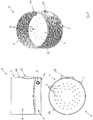
- Fig. 1 schematically shows three views of an embodiment of a module base 1.
- the module foot 1 has a compressed air region 2 with a compressed air inlet 3.
- the module foot 1 a raw water area 8 with a raw water inlet 10.
- the raw water area 8 and the compressed air area 2 are separated from each other by means of a partition 4.
- the partition wall 4 has perforated openings 5 designed as passage openings which fluidly connect the raw water area 8 with the compressed air area 2.
- the module foot 1 has a housing 6.
- the housing 6 is approximately cup-shaped. Accordingly, the housing 6 has a bottom 6a and a side wall 6b. Spaced to the bottom 6a, the partition wall 4 is arranged.
- the dividing wall 4 also extends over the entire cross section of the interior of the housing 6 surrounding the side wall 6b.
- the dividing wall 4 is arched.
- a middle part of the partition wall 4 is in the normal direction to the bottom 6a farther away from the ground than an outer part.
- the compressed air inlet 3 is formed as a passage opening through the side wall 6b in a region between the bottom 6a and the partition 4.
- the raw water inlet 10 is formed as a passage opening through the side wall in a region above the bottom 6a and above the partition wall 4.
- the dividing wall 4 has a plurality of perforated openings 5 formed as a passage opening.
- the bead holes 5 are arranged in an annular pattern around the middle part.
- no bead openings 5 are provided in an outer ring area as well as in the central area.
- the bead openings are spaced apart in three concentric ring lines, in the circumferential direction. arranged around the middle part.
- the bead openings 5 are formed the same size.
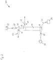
- Fig. 2 1 schematically shows a circuit diagram of an embodiment of a filter device 200.
- the filter device 200 comprises a membrane filter unit 40.
- the membrane filter unit 40 is fluidically connected to the module base 1 at its lower end. At its upper end, the membrane filter unit 40 is fluidically connected to a module head 13.
- the module foot 1 is fluidically connected via the compressed air region 2 and with the Druck Kunststoffzugschreib 3 with a compressed air generator 14.
- the module foot 1 is fluidly connected to the raw water region 8 via the raw water inlet 10 with a raw water pump 31.
- a shut-off element 15 is provided between the raw water pump 31 and the raw water inlet 10.
- the module head 13 has a discharge 60 for the wastewater or contaminated flushing fluid.
- a wastewater drain is controllable via a shut-off device 62, which is fluidically connected to the module head 13. Further, the module head 13 is connected to a supply 65 for the flushing fluid. Rinse water passes through a pump 32 for the rinse fluid / rinse water / backwash water to the module head 13. Interposed is a shut-off 67 for the backwash fluid to regulate the Ruth Cyprusfluidiser to the module head 13. From the supply 65 branches off a clean water discharge 52. The clean water discharge 52 also has a shut-off device 53 for the regulation of the pure water flow.
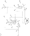
- Fig. 3 schematically another embodiment of a filter device 200.
- a supply of raw water on the raw water inlet or the raw water supply is provided.
- the raw water is fed via the module foot 1 of the device 200.
- the supply of additional filter means via a suitable feeder.
- the additional filter means are presently designed as powdered activated carbon.
- the powdered activated carbon is fed to the raw water.
- a conveying device 30 in the form of a pump 31 is provided in order to convey the raw water together with powder activated carbon to a membrane filter unit 40.
- the membrane filter unit 40 has a plurality of membrane filter elements 41, by or in which the raw water of a Raw water side 11 is conveyed in the filter direction 12 to a clean water side 45.
- the membrane filter unit 40 forms with the corresponding connections and supply and discharge means a first filter stage 50.
- the recovered pure water is discharged on the clean water side 45 of the membrane filter unit 40 for further use.
- the membrane filter unit 40 is switched from the filter operation described above to a backwash.
- the recovered pure water is conveyed at 65 in the (back) rinsing direction, that is to say counter to the filter direction 12 into the membrane filter unit 40 via a conveying device, which is designed as a pump 32 in the FIGURE.
- the contaminated flushing fluid which is presently designed as muddy water, led to a second filter stage 100.
- the contaminated fluid is first passed into a sedimentation tank 110.
- the sludge 101 is at least partially separated from the water by sedimentation.
- the sludge 101 which settles in the sedimentation tank 110 is removed at 120 for further use.
- the water is also discharged at 130.
- a pump 140 is provided.
- the pump 140 conveys the water from the sedimentation tank 110 into a further membrane filter unit 150.
- the filtration process is analogous to the first filter stage 50.
- the pure water or filtrate obtained in the second filter stage 100 is removed at 160 from the membrane filter unit 150 in filter operation in the filter direction.
- the pure water recovered in the second filter stage 100 is supplied to the raw water to the first filter stage 50 at 170.
- a cycle is thus closed.
- the contaminated flushing fluid obtained in the second filter stage 100 according to the same principle as in the first filter stage 50 is removed at 180 and fed to the contaminated flushing fluid removed from the first filter stage 50 for further supply to the second filter stage 100. In this way, a second cycle is closed.
Landscapes
- Engineering & Computer Science (AREA)
- Water Supply & Treatment (AREA)
- Chemical & Material Sciences (AREA)
- Chemical Kinetics & Catalysis (AREA)
- Life Sciences & Earth Sciences (AREA)
- Hydrology & Water Resources (AREA)
- Environmental & Geological Engineering (AREA)
- Organic Chemistry (AREA)
- Separation Using Semi-Permeable Membranes (AREA)
Applications Claiming Priority (1)
| Application Number | Priority Date | Filing Date | Title |
|---|---|---|---|
| DE102017108684.6A DE102017108684B3 (de) | 2017-04-24 | 2017-04-24 | Modulfuß, Vorrichtung und Verfahren zum Filtern eines eine Verschmutzung enthaltenden Rohfluids mittels mindestens einer Membranfiltereinheit sowie eine Verwendung hierzu |
Publications (2)
| Publication Number | Publication Date |
|---|---|
| EP3378554A1 true EP3378554A1 (fr) | 2018-09-26 |
| EP3378554B1 EP3378554B1 (fr) | 2022-11-02 |
Family
ID=61763847
Family Applications (1)
| Application Number | Title | Priority Date | Filing Date |
|---|---|---|---|
| EP18163518.6A Active EP3378554B1 (fr) | 2017-04-24 | 2018-03-23 | Pied modulaire, procédé et dispositif de filtration d'un fluide brut contenant une impureté au moyen d'au moins une unité de filtre à membrane ainsi que leur utilisation |
Country Status (2)
| Country | Link |
|---|---|
| EP (1) | EP3378554B1 (fr) |
| DE (1) | DE102017108684B3 (fr) |
Families Citing this family (2)
| Publication number | Priority date | Publication date | Assignee | Title |
|---|---|---|---|---|
| CN111871212B (zh) * | 2020-08-18 | 2025-01-07 | 常州科德水处理成套设备股份有限公司 | 一种自清洗智能膜池装置 |
| CN113274884A (zh) * | 2021-05-25 | 2021-08-20 | 重庆中轻装备有限公司 | 一种活性炭陶瓷膜错流过滤系统及过滤反冲洗工艺 |
Citations (3)
| Publication number | Priority date | Publication date | Assignee | Title |
|---|---|---|---|---|
| WO2008028626A1 (fr) * | 2006-09-06 | 2008-03-13 | Berghof Filtrations- Und Anlagentechnik Gmbh & Co. Kg | Système de filtrage comportant un système de ventilation |
| WO2013100272A1 (fr) * | 2011-12-28 | 2013-07-04 | 웅진케미칼 주식회사 | Appareil de purification de l'eau comprenant un module membranaire pressurisé |
| WO2015086303A1 (fr) * | 2013-12-11 | 2015-06-18 | Siemens Aktiengesellschaft | Système de filtre et récipient pour le système de filtre |
Family Cites Families (4)
| Publication number | Priority date | Publication date | Assignee | Title |
|---|---|---|---|---|
| KR100405152B1 (ko) * | 2001-06-07 | 2003-11-14 | 은석규 | 간단한 구조로 사이드 스트림 여과와 클로스 플로우여과가 가능한 가변세공 정밀 여과장치 |
| US7122121B1 (en) * | 2004-05-28 | 2006-10-17 | Jiang Ji | Advanced submerged membrane modules, systems and processes |
| DE102005033314B4 (de) | 2005-07-16 | 2008-11-13 | Bödrich & Strecker Anlagenbau GmbH | Verfahren und Filteranlage zum Filtern von Rohwasser |
| CN204051452U (zh) * | 2014-07-23 | 2014-12-31 | 科氏滤膜系统公司 | 用于从水中除去污染物的单顶盖过滤筒 |
-
2017
- 2017-04-24 DE DE102017108684.6A patent/DE102017108684B3/de not_active Expired - Fee Related
-
2018
- 2018-03-23 EP EP18163518.6A patent/EP3378554B1/fr active Active
Patent Citations (3)
| Publication number | Priority date | Publication date | Assignee | Title |
|---|---|---|---|---|
| WO2008028626A1 (fr) * | 2006-09-06 | 2008-03-13 | Berghof Filtrations- Und Anlagentechnik Gmbh & Co. Kg | Système de filtrage comportant un système de ventilation |
| WO2013100272A1 (fr) * | 2011-12-28 | 2013-07-04 | 웅진케미칼 주식회사 | Appareil de purification de l'eau comprenant un module membranaire pressurisé |
| WO2015086303A1 (fr) * | 2013-12-11 | 2015-06-18 | Siemens Aktiengesellschaft | Système de filtre et récipient pour le système de filtre |
Also Published As
| Publication number | Publication date |
|---|---|
| EP3378554B1 (fr) | 2022-11-02 |
| DE102017108684B3 (de) | 2018-05-09 |
Similar Documents
| Publication | Publication Date | Title |
|---|---|---|
| DE60104188T2 (de) | Verfahren und vorrichtung zur behandlung von wasser/abwasser | |
| EP0654294B1 (fr) | Procédé et dispositif de filtration de particules solides de liquides et le rinçage du filtre à contre-courant | |
| DE19648519A1 (de) | Verfahren und Anlage zur Stofftrennung mittels Membranfiltration | |
| EP1147803B1 (fr) | Appareil de filtration et de séparation de fluides, notamment de fluides biologiques-organiques | |
| EP2016992B1 (fr) | Dispositif et procédé destinés au traitement de liquides de nettoyage utilisés dans des brasseries | |
| EP0951327A1 (fr) | Dispositif pour filtrer des liquides en continu | |
| EP1512450A1 (fr) | Dispositif de filtration | |
| EP3378554B1 (fr) | Pied modulaire, procédé et dispositif de filtration d'un fluide brut contenant une impureté au moyen d'au moins une unité de filtre à membrane ainsi que leur utilisation | |
| DE69836703T2 (de) | Vorrichtung zur Bierfiltration | |
| EP1568662B1 (fr) | Bioreacteur à membrane et méthode de traitement des eaux résiduelles | |
| DE102005033314B4 (de) | Verfahren und Filteranlage zum Filtern von Rohwasser | |
| EP3338877B1 (fr) | Procédé et dispositif de filtration d'un fluide brut contenant une impureté au moyen d'au moins une unité de filtre à membrane ainsi que leur utilisation | |
| EP1820563A1 (fr) | Filtre, jeu de remplacement pour un filtre et procédé de filtrage de liquides | |
| EP2070574A1 (fr) | Filtre à pression et procédé destiné à l'épuration de liquides | |
| EP1265819B1 (fr) | Procede et dispositif pour l'epuration d'eaux usees | |
| DE19703877C1 (de) | Verfahren und Vorrichtung zur Reinigung einer Filtermembran | |
| DE2436965C2 (de) | Filter zum Filtern von Flüssigkeiten | |
| EP1803688B1 (fr) | Bioréacteur à membrane et procédé de traitement biologique des eaux usées huileuses | |
| DE202005011219U1 (de) | Filteranlage zum Filtern von Rohwasser | |
| EP1441829B1 (fr) | Dispositif et procede de purification d'eaux usees | |
| DE102006001034A1 (de) | Verfahren und Filteranlage zum Filtern von Rohwasser | |
| WO2001051186A1 (fr) | Procede et dispositif pour liberer des chemins d'ecoulement dans des modules de filtration | |
| EP1618072B1 (fr) | Procede et dispositif de traitement de milieux fluides au moyen d'un reacteur a filtre | |
| EP4541774A1 (fr) | Bassin filtrant à écoulement parallèle pour l'épuration des eaux usées | |
| EP0765293B1 (fr) | Dispositif d'epuration biologique et procede d'epuration d'eaux usees faisant appel audit dispositif |
Legal Events
| Date | Code | Title | Description |
|---|---|---|---|
| PUAI | Public reference made under article 153(3) epc to a published international application that has entered the european phase |
Free format text: ORIGINAL CODE: 0009012 |
|
| STAA | Information on the status of an ep patent application or granted ep patent |
Free format text: STATUS: THE APPLICATION HAS BEEN PUBLISHED |
|
| AK | Designated contracting states |
Kind code of ref document: A1 Designated state(s): AL AT BE BG CH CY CZ DE DK EE ES FI FR GB GR HR HU IE IS IT LI LT LU LV MC MK MT NL NO PL PT RO RS SE SI SK SM TR |
|
| AX | Request for extension of the european patent |
Extension state: BA ME |
|
| STAA | Information on the status of an ep patent application or granted ep patent |
Free format text: STATUS: REQUEST FOR EXAMINATION WAS MADE |
|
| 17P | Request for examination filed |
Effective date: 20190128 |
|
| RBV | Designated contracting states (corrected) |
Designated state(s): AL AT BE BG CH CY CZ DE DK EE ES FI FR GB GR HR HU IE IS IT LI LT LU LV MC MK MT NL NO PL PT RO RS SE SI SK SM TR |
|
| STAA | Information on the status of an ep patent application or granted ep patent |
Free format text: STATUS: EXAMINATION IS IN PROGRESS |
|
| 17Q | First examination report despatched |
Effective date: 20190905 |
|
| GRAP | Despatch of communication of intention to grant a patent |
Free format text: ORIGINAL CODE: EPIDOSNIGR1 |
|
| STAA | Information on the status of an ep patent application or granted ep patent |
Free format text: STATUS: GRANT OF PATENT IS INTENDED |
|
| INTG | Intention to grant announced |
Effective date: 20220803 |
|
| GRAS | Grant fee paid |
Free format text: ORIGINAL CODE: EPIDOSNIGR3 |
|
| GRAA | (expected) grant |
Free format text: ORIGINAL CODE: 0009210 |
|
| STAA | Information on the status of an ep patent application or granted ep patent |
Free format text: STATUS: THE PATENT HAS BEEN GRANTED |
|
| AK | Designated contracting states |
Kind code of ref document: B1 Designated state(s): AL AT BE BG CH CY CZ DE DK EE ES FI FR GB GR HR HU IE IS IT LI LT LU LV MC MK MT NL NO PL PT RO RS SE SI SK SM TR |
|
| REG | Reference to a national code |
Ref country code: GB Ref legal event code: FG4D Free format text: NOT ENGLISH |
|
| REG | Reference to a national code |
Ref country code: CH Ref legal event code: EP Ref country code: AT Ref legal event code: REF Ref document number: 1528339 Country of ref document: AT Kind code of ref document: T Effective date: 20221115 |
|
| REG | Reference to a national code |
Ref country code: DE Ref legal event code: R096 Ref document number: 502018010942 Country of ref document: DE |
|
| REG | Reference to a national code |
Ref country code: IE Ref legal event code: FG4D Free format text: LANGUAGE OF EP DOCUMENT: GERMAN |
|
| REG | Reference to a national code |
Ref country code: LT Ref legal event code: MG9D |
|
| REG | Reference to a national code |
Ref country code: NL Ref legal event code: MP Effective date: 20221102 |
|
| PG25 | Lapsed in a contracting state [announced via postgrant information from national office to epo] |
Ref country code: SE Free format text: LAPSE BECAUSE OF FAILURE TO SUBMIT A TRANSLATION OF THE DESCRIPTION OR TO PAY THE FEE WITHIN THE PRESCRIBED TIME-LIMIT Effective date: 20221102 Ref country code: PT Free format text: LAPSE BECAUSE OF FAILURE TO SUBMIT A TRANSLATION OF THE DESCRIPTION OR TO PAY THE FEE WITHIN THE PRESCRIBED TIME-LIMIT Effective date: 20230302 Ref country code: NO Free format text: LAPSE BECAUSE OF FAILURE TO SUBMIT A TRANSLATION OF THE DESCRIPTION OR TO PAY THE FEE WITHIN THE PRESCRIBED TIME-LIMIT Effective date: 20230202 Ref country code: LT Free format text: LAPSE BECAUSE OF FAILURE TO SUBMIT A TRANSLATION OF THE DESCRIPTION OR TO PAY THE FEE WITHIN THE PRESCRIBED TIME-LIMIT Effective date: 20221102 Ref country code: FI Free format text: LAPSE BECAUSE OF FAILURE TO SUBMIT A TRANSLATION OF THE DESCRIPTION OR TO PAY THE FEE WITHIN THE PRESCRIBED TIME-LIMIT Effective date: 20221102 Ref country code: ES Free format text: LAPSE BECAUSE OF FAILURE TO SUBMIT A TRANSLATION OF THE DESCRIPTION OR TO PAY THE FEE WITHIN THE PRESCRIBED TIME-LIMIT Effective date: 20221102 |
|
| PG25 | Lapsed in a contracting state [announced via postgrant information from national office to epo] |
Ref country code: RS Free format text: LAPSE BECAUSE OF FAILURE TO SUBMIT A TRANSLATION OF THE DESCRIPTION OR TO PAY THE FEE WITHIN THE PRESCRIBED TIME-LIMIT Effective date: 20221102 Ref country code: PL Free format text: LAPSE BECAUSE OF FAILURE TO SUBMIT A TRANSLATION OF THE DESCRIPTION OR TO PAY THE FEE WITHIN THE PRESCRIBED TIME-LIMIT Effective date: 20221102 Ref country code: LV Free format text: LAPSE BECAUSE OF FAILURE TO SUBMIT A TRANSLATION OF THE DESCRIPTION OR TO PAY THE FEE WITHIN THE PRESCRIBED TIME-LIMIT Effective date: 20221102 Ref country code: IS Free format text: LAPSE BECAUSE OF FAILURE TO SUBMIT A TRANSLATION OF THE DESCRIPTION OR TO PAY THE FEE WITHIN THE PRESCRIBED TIME-LIMIT Effective date: 20230302 Ref country code: HR Free format text: LAPSE BECAUSE OF FAILURE TO SUBMIT A TRANSLATION OF THE DESCRIPTION OR TO PAY THE FEE WITHIN THE PRESCRIBED TIME-LIMIT Effective date: 20221102 Ref country code: GR Free format text: LAPSE BECAUSE OF FAILURE TO SUBMIT A TRANSLATION OF THE DESCRIPTION OR TO PAY THE FEE WITHIN THE PRESCRIBED TIME-LIMIT Effective date: 20230203 |
|
| PG25 | Lapsed in a contracting state [announced via postgrant information from national office to epo] |
Ref country code: NL Free format text: LAPSE BECAUSE OF FAILURE TO SUBMIT A TRANSLATION OF THE DESCRIPTION OR TO PAY THE FEE WITHIN THE PRESCRIBED TIME-LIMIT Effective date: 20221102 |
|
| PG25 | Lapsed in a contracting state [announced via postgrant information from national office to epo] |
Ref country code: SM Free format text: LAPSE BECAUSE OF FAILURE TO SUBMIT A TRANSLATION OF THE DESCRIPTION OR TO PAY THE FEE WITHIN THE PRESCRIBED TIME-LIMIT Effective date: 20221102 Ref country code: RO Free format text: LAPSE BECAUSE OF FAILURE TO SUBMIT A TRANSLATION OF THE DESCRIPTION OR TO PAY THE FEE WITHIN THE PRESCRIBED TIME-LIMIT Effective date: 20221102 Ref country code: EE Free format text: LAPSE BECAUSE OF FAILURE TO SUBMIT A TRANSLATION OF THE DESCRIPTION OR TO PAY THE FEE WITHIN THE PRESCRIBED TIME-LIMIT Effective date: 20221102 Ref country code: DK Free format text: LAPSE BECAUSE OF FAILURE TO SUBMIT A TRANSLATION OF THE DESCRIPTION OR TO PAY THE FEE WITHIN THE PRESCRIBED TIME-LIMIT Effective date: 20221102 Ref country code: CZ Free format text: LAPSE BECAUSE OF FAILURE TO SUBMIT A TRANSLATION OF THE DESCRIPTION OR TO PAY THE FEE WITHIN THE PRESCRIBED TIME-LIMIT Effective date: 20221102 |
|
| REG | Reference to a national code |
Ref country code: DE Ref legal event code: R097 Ref document number: 502018010942 Country of ref document: DE |
|
| PG25 | Lapsed in a contracting state [announced via postgrant information from national office to epo] |
Ref country code: SK Free format text: LAPSE BECAUSE OF FAILURE TO SUBMIT A TRANSLATION OF THE DESCRIPTION OR TO PAY THE FEE WITHIN THE PRESCRIBED TIME-LIMIT Effective date: 20221102 Ref country code: AL Free format text: LAPSE BECAUSE OF FAILURE TO SUBMIT A TRANSLATION OF THE DESCRIPTION OR TO PAY THE FEE WITHIN THE PRESCRIBED TIME-LIMIT Effective date: 20221102 |
|
| PLBE | No opposition filed within time limit |
Free format text: ORIGINAL CODE: 0009261 |
|
| STAA | Information on the status of an ep patent application or granted ep patent |
Free format text: STATUS: NO OPPOSITION FILED WITHIN TIME LIMIT |
|
| 26N | No opposition filed |
Effective date: 20230803 |
|
| PG25 | Lapsed in a contracting state [announced via postgrant information from national office to epo] |
Ref country code: MC Free format text: LAPSE BECAUSE OF FAILURE TO SUBMIT A TRANSLATION OF THE DESCRIPTION OR TO PAY THE FEE WITHIN THE PRESCRIBED TIME-LIMIT Effective date: 20221102 |
|
| GBPC | Gb: european patent ceased through non-payment of renewal fee |
Effective date: 20230323 |
|
| PG25 | Lapsed in a contracting state [announced via postgrant information from national office to epo] |
Ref country code: SI Free format text: LAPSE BECAUSE OF FAILURE TO SUBMIT A TRANSLATION OF THE DESCRIPTION OR TO PAY THE FEE WITHIN THE PRESCRIBED TIME-LIMIT Effective date: 20221102 |
|
| REG | Reference to a national code |
Ref country code: BE Ref legal event code: MM Effective date: 20230331 |
|
| PG25 | Lapsed in a contracting state [announced via postgrant information from national office to epo] |
Ref country code: LU Free format text: LAPSE BECAUSE OF NON-PAYMENT OF DUE FEES Effective date: 20230323 |
|
| REG | Reference to a national code |
Ref country code: IE Ref legal event code: MM4A |
|
| PG25 | Lapsed in a contracting state [announced via postgrant information from national office to epo] |
Ref country code: GB Free format text: LAPSE BECAUSE OF NON-PAYMENT OF DUE FEES Effective date: 20230323 |
|
| PG25 | Lapsed in a contracting state [announced via postgrant information from national office to epo] |
Ref country code: IE Free format text: LAPSE BECAUSE OF NON-PAYMENT OF DUE FEES Effective date: 20230323 Ref country code: GB Free format text: LAPSE BECAUSE OF NON-PAYMENT OF DUE FEES Effective date: 20230323 Ref country code: FR Free format text: LAPSE BECAUSE OF NON-PAYMENT OF DUE FEES Effective date: 20230331 |
|
| PG25 | Lapsed in a contracting state [announced via postgrant information from national office to epo] |
Ref country code: BE Free format text: LAPSE BECAUSE OF NON-PAYMENT OF DUE FEES Effective date: 20230331 |
|
| PG25 | Lapsed in a contracting state [announced via postgrant information from national office to epo] |
Ref country code: IT Free format text: LAPSE BECAUSE OF FAILURE TO SUBMIT A TRANSLATION OF THE DESCRIPTION OR TO PAY THE FEE WITHIN THE PRESCRIBED TIME-LIMIT Effective date: 20221102 |
|
| PG25 | Lapsed in a contracting state [announced via postgrant information from national office to epo] |
Ref country code: BG Free format text: LAPSE BECAUSE OF FAILURE TO SUBMIT A TRANSLATION OF THE DESCRIPTION OR TO PAY THE FEE WITHIN THE PRESCRIBED TIME-LIMIT Effective date: 20221102 |
|
| PG25 | Lapsed in a contracting state [announced via postgrant information from national office to epo] |
Ref country code: BG Free format text: LAPSE BECAUSE OF FAILURE TO SUBMIT A TRANSLATION OF THE DESCRIPTION OR TO PAY THE FEE WITHIN THE PRESCRIBED TIME-LIMIT Effective date: 20221102 |
|
| PGFP | Annual fee paid to national office [announced via postgrant information from national office to epo] |
Ref country code: CH Payment date: 20250423 Year of fee payment: 8 |
|
| PG25 | Lapsed in a contracting state [announced via postgrant information from national office to epo] |
Ref country code: CY Free format text: LAPSE BECAUSE OF FAILURE TO SUBMIT A TRANSLATION OF THE DESCRIPTION OR TO PAY THE FEE WITHIN THE PRESCRIBED TIME-LIMIT; INVALID AB INITIO Effective date: 20180323 |
|
| PG25 | Lapsed in a contracting state [announced via postgrant information from national office to epo] |
Ref country code: HU Free format text: LAPSE BECAUSE OF FAILURE TO SUBMIT A TRANSLATION OF THE DESCRIPTION OR TO PAY THE FEE WITHIN THE PRESCRIBED TIME-LIMIT; INVALID AB INITIO Effective date: 20180323 |
|
| PG25 | Lapsed in a contracting state [announced via postgrant information from national office to epo] |
Ref country code: TR Free format text: LAPSE BECAUSE OF FAILURE TO SUBMIT A TRANSLATION OF THE DESCRIPTION OR TO PAY THE FEE WITHIN THE PRESCRIBED TIME-LIMIT Effective date: 20221102 |
|
| REG | Reference to a national code |
Ref country code: CH Ref legal event code: U11 Free format text: ST27 STATUS EVENT CODE: U-0-0-U10-U11 (AS PROVIDED BY THE NATIONAL OFFICE) Effective date: 20260401 |
|
| PGFP | Annual fee paid to national office [announced via postgrant information from national office to epo] |
Ref country code: DE Payment date: 20260320 Year of fee payment: 9 |
|
| PGFP | Annual fee paid to national office [announced via postgrant information from national office to epo] |
Ref country code: AT Payment date: 20260319 Year of fee payment: 9 |