EP3378563A2 - Appareil de distribution de gouttelettes - Google Patents
Appareil de distribution de gouttelettes Download PDFInfo
- Publication number
- EP3378563A2 EP3378563A2 EP18159404.5A EP18159404A EP3378563A2 EP 3378563 A2 EP3378563 A2 EP 3378563A2 EP 18159404 A EP18159404 A EP 18159404A EP 3378563 A2 EP3378563 A2 EP 3378563A2
- Authority
- EP
- European Patent Office
- Prior art keywords
- microplate
- transparency
- droplet
- weight
- initial
- Prior art date
- Legal status (The legal status is an assumption and is not a legal conclusion. Google has not performed a legal analysis and makes no representation as to the accuracy of the status listed.)
- Granted
Links
Images


Classifications
-
- B—PERFORMING OPERATIONS; TRANSPORTING
- B01—PHYSICAL OR CHEMICAL PROCESSES OR APPARATUS IN GENERAL
- B01L—CHEMICAL OR PHYSICAL LABORATORY APPARATUS FOR GENERAL USE
- B01L3/00—Containers or dishes for laboratory use, e.g. laboratory glassware; Droppers
- B01L3/02—Burettes; Pipettes
- B01L3/0241—Drop counters; Drop formers
- B01L3/0268—Drop counters; Drop formers using pulse dispensing or spraying, eg. inkjet type, piezo actuated ejection of droplets from capillaries
-
- B—PERFORMING OPERATIONS; TRANSPORTING
- B41—PRINTING; LINING MACHINES; TYPEWRITERS; STAMPS
- B41J—TYPEWRITERS; SELECTIVE PRINTING MECHANISMS, i.e. MECHANISMS PRINTING OTHERWISE THAN FROM A FORME; CORRECTION OF TYPOGRAPHICAL ERRORS
- B41J2/00—Typewriters or selective printing mechanisms characterised by the printing or marking process for which they are designed
- B41J2/005—Typewriters or selective printing mechanisms characterised by the printing or marking process for which they are designed characterised by bringing liquid or particles selectively into contact with a printing material
- B41J2/01—Ink jet
- B41J2/015—Ink jet characterised by the jet generation process
- B41J2/04—Ink jet characterised by the jet generation process generating single droplets or particles on demand
-
- B—PERFORMING OPERATIONS; TRANSPORTING
- B01—PHYSICAL OR CHEMICAL PROCESSES OR APPARATUS IN GENERAL
- B01L—CHEMICAL OR PHYSICAL LABORATORY APPARATUS FOR GENERAL USE
- B01L9/00—Supporting devices; Holding devices
- B01L9/54—Supports specially adapted for pipettes and burettes
-
- B—PERFORMING OPERATIONS; TRANSPORTING
- B41—PRINTING; LINING MACHINES; TYPEWRITERS; STAMPS
- B41J—TYPEWRITERS; SELECTIVE PRINTING MECHANISMS, i.e. MECHANISMS PRINTING OTHERWISE THAN FROM A FORME; CORRECTION OF TYPOGRAPHICAL ERRORS
- B41J2/00—Typewriters or selective printing mechanisms characterised by the printing or marking process for which they are designed
- B41J2/005—Typewriters or selective printing mechanisms characterised by the printing or marking process for which they are designed characterised by bringing liquid or particles selectively into contact with a printing material
- B41J2/01—Ink jet
- B41J2/015—Ink jet characterised by the jet generation process
- B41J2/04—Ink jet characterised by the jet generation process generating single droplets or particles on demand
- B41J2/045—Ink jet characterised by the jet generation process generating single droplets or particles on demand by pressure, e.g. electromechanical transducers
- B41J2/04501—Control methods or devices therefor, e.g. driver circuits, control circuits
- B41J2/04581—Control methods or devices therefor, e.g. driver circuits, control circuits controlling heads based on piezoelectric elements
-
- B—PERFORMING OPERATIONS; TRANSPORTING
- B41—PRINTING; LINING MACHINES; TYPEWRITERS; STAMPS
- B41J—TYPEWRITERS; SELECTIVE PRINTING MECHANISMS, i.e. MECHANISMS PRINTING OTHERWISE THAN FROM A FORME; CORRECTION OF TYPOGRAPHICAL ERRORS
- B41J2/00—Typewriters or selective printing mechanisms characterised by the printing or marking process for which they are designed
- B41J2/005—Typewriters or selective printing mechanisms characterised by the printing or marking process for which they are designed characterised by bringing liquid or particles selectively into contact with a printing material
- B41J2/01—Ink jet
- B41J2/135—Nozzles
- B41J2/14—Structure thereof only for on-demand ink jet heads
- B41J2/14016—Structure of bubble jet print heads
- B41J2/14032—Structure of the pressure chamber
- B41J2/14048—Movable member in the chamber
-
- B—PERFORMING OPERATIONS; TRANSPORTING
- B41—PRINTING; LINING MACHINES; TYPEWRITERS; STAMPS
- B41J—TYPEWRITERS; SELECTIVE PRINTING MECHANISMS, i.e. MECHANISMS PRINTING OTHERWISE THAN FROM A FORME; CORRECTION OF TYPOGRAPHICAL ERRORS
- B41J2/00—Typewriters or selective printing mechanisms characterised by the printing or marking process for which they are designed
- B41J2/005—Typewriters or selective printing mechanisms characterised by the printing or marking process for which they are designed characterised by bringing liquid or particles selectively into contact with a printing material
- B41J2/01—Ink jet
- B41J2/135—Nozzles
- B41J2/14—Structure thereof only for on-demand ink jet heads
- B41J2/14016—Structure of bubble jet print heads
- B41J2/14153—Structures including a sensor
-
- B—PERFORMING OPERATIONS; TRANSPORTING
- B41—PRINTING; LINING MACHINES; TYPEWRITERS; STAMPS
- B41J—TYPEWRITERS; SELECTIVE PRINTING MECHANISMS, i.e. MECHANISMS PRINTING OTHERWISE THAN FROM A FORME; CORRECTION OF TYPOGRAPHICAL ERRORS
- B41J2/00—Typewriters or selective printing mechanisms characterised by the printing or marking process for which they are designed
- B41J2/005—Typewriters or selective printing mechanisms characterised by the printing or marking process for which they are designed characterised by bringing liquid or particles selectively into contact with a printing material
- B41J2/01—Ink jet
- B41J2/135—Nozzles
- B41J2/14—Structure thereof only for on-demand ink jet heads
- B41J2/14201—Structure of print heads with piezoelectric elements
-
- B—PERFORMING OPERATIONS; TRANSPORTING
- B41—PRINTING; LINING MACHINES; TYPEWRITERS; STAMPS
- B41J—TYPEWRITERS; SELECTIVE PRINTING MECHANISMS, i.e. MECHANISMS PRINTING OTHERWISE THAN FROM A FORME; CORRECTION OF TYPOGRAPHICAL ERRORS
- B41J2/00—Typewriters or selective printing mechanisms characterised by the printing or marking process for which they are designed
- B41J2/005—Typewriters or selective printing mechanisms characterised by the printing or marking process for which they are designed characterised by bringing liquid or particles selectively into contact with a printing material
- B41J2/01—Ink jet
- B41J2/135—Nozzles
- B41J2/14—Structure thereof only for on-demand ink jet heads
- B41J2/1433—Structure of nozzle plates
-
- G—PHYSICS
- G01—MEASURING; TESTING
- G01N—INVESTIGATING OR ANALYSING MATERIALS BY DETERMINING THEIR CHEMICAL OR PHYSICAL PROPERTIES
- G01N35/00—Automatic analysis not limited to methods or materials provided for in any single one of groups G01N1/00 - G01N33/00; Handling materials therefor
- G01N35/10—Devices for transferring samples or any liquids to, in, or from, the analysis apparatus, e.g. suction devices, injection devices
- G01N35/1009—Characterised by arrangements for controlling the aspiration or dispense of liquids
- G01N35/1016—Control of the volume dispensed or introduced
-
- G—PHYSICS
- G01—MEASURING; TESTING
- G01N—INVESTIGATING OR ANALYSING MATERIALS BY DETERMINING THEIR CHEMICAL OR PHYSICAL PROPERTIES
- G01N35/00—Automatic analysis not limited to methods or materials provided for in any single one of groups G01N1/00 - G01N33/00; Handling materials therefor
- G01N35/10—Devices for transferring samples or any liquids to, in, or from, the analysis apparatus, e.g. suction devices, injection devices
- G01N35/1065—Multiple transfer devices
-
- B—PERFORMING OPERATIONS; TRANSPORTING
- B01—PHYSICAL OR CHEMICAL PROCESSES OR APPARATUS IN GENERAL
- B01L—CHEMICAL OR PHYSICAL LABORATORY APPARATUS FOR GENERAL USE
- B01L2200/00—Solutions for specific problems relating to chemical or physical laboratory apparatus
- B01L2200/06—Fluid handling related problems
- B01L2200/0605—Metering of fluids
-
- B—PERFORMING OPERATIONS; TRANSPORTING
- B01—PHYSICAL OR CHEMICAL PROCESSES OR APPARATUS IN GENERAL
- B01L—CHEMICAL OR PHYSICAL LABORATORY APPARATUS FOR GENERAL USE
- B01L2200/00—Solutions for specific problems relating to chemical or physical laboratory apparatus
- B01L2200/14—Process control and prevention of errors
- B01L2200/143—Quality control, feedback systems
-
- B—PERFORMING OPERATIONS; TRANSPORTING
- B01—PHYSICAL OR CHEMICAL PROCESSES OR APPARATUS IN GENERAL
- B01L—CHEMICAL OR PHYSICAL LABORATORY APPARATUS FOR GENERAL USE
- B01L2300/00—Additional constructional details
- B01L2300/08—Geometry, shape and general structure
- B01L2300/0809—Geometry, shape and general structure rectangular shaped
- B01L2300/0816—Cards, e.g. flat sample carriers usually with flow in two horizontal directions
-
- B—PERFORMING OPERATIONS; TRANSPORTING
- B01—PHYSICAL OR CHEMICAL PROCESSES OR APPARATUS IN GENERAL
- B01L—CHEMICAL OR PHYSICAL LABORATORY APPARATUS FOR GENERAL USE
- B01L3/00—Containers or dishes for laboratory use, e.g. laboratory glassware; Droppers
- B01L3/02—Burettes; Pipettes
- B01L3/021—Pipettes, i.e. with only one conduit for withdrawing and redistributing liquids
- B01L3/0217—Pipettes, i.e. with only one conduit for withdrawing and redistributing liquids of the plunger pump type
- B01L3/0237—Details of electronic control, e.g. relating to user interface
-
- B—PERFORMING OPERATIONS; TRANSPORTING
- B41—PRINTING; LINING MACHINES; TYPEWRITERS; STAMPS
- B41J—TYPEWRITERS; SELECTIVE PRINTING MECHANISMS, i.e. MECHANISMS PRINTING OTHERWISE THAN FROM A FORME; CORRECTION OF TYPOGRAPHICAL ERRORS
- B41J2/00—Typewriters or selective printing mechanisms characterised by the printing or marking process for which they are designed
- B41J2/005—Typewriters or selective printing mechanisms characterised by the printing or marking process for which they are designed characterised by bringing liquid or particles selectively into contact with a printing material
- B41J2/01—Ink jet
- B41J2/135—Nozzles
- B41J2/14—Structure thereof only for on-demand ink jet heads
- B41J2/14201—Structure of print heads with piezoelectric elements
- B41J2/14233—Structure of print heads with piezoelectric elements of film type, deformed by bending and disposed on a diaphragm
- B41J2002/14241—Structure of print heads with piezoelectric elements of film type, deformed by bending and disposed on a diaphragm having a cover around the piezoelectric thin film element
-
- B—PERFORMING OPERATIONS; TRANSPORTING
- B41—PRINTING; LINING MACHINES; TYPEWRITERS; STAMPS
- B41J—TYPEWRITERS; SELECTIVE PRINTING MECHANISMS, i.e. MECHANISMS PRINTING OTHERWISE THAN FROM A FORME; CORRECTION OF TYPOGRAPHICAL ERRORS
- B41J2/00—Typewriters or selective printing mechanisms characterised by the printing or marking process for which they are designed
- B41J2/005—Typewriters or selective printing mechanisms characterised by the printing or marking process for which they are designed characterised by bringing liquid or particles selectively into contact with a printing material
- B41J2/01—Ink jet
- B41J2/135—Nozzles
- B41J2/14—Structure thereof only for on-demand ink jet heads
- B41J2002/14475—Structure thereof only for on-demand ink jet heads characterised by nozzle shapes or number of orifices per chamber
-
- B—PERFORMING OPERATIONS; TRANSPORTING
- B41—PRINTING; LINING MACHINES; TYPEWRITERS; STAMPS
- B41J—TYPEWRITERS; SELECTIVE PRINTING MECHANISMS, i.e. MECHANISMS PRINTING OTHERWISE THAN FROM A FORME; CORRECTION OF TYPOGRAPHICAL ERRORS
- B41J2202/00—Embodiments of or processes related to ink-jet or thermal heads
- B41J2202/01—Embodiments of or processes related to ink-jet heads
- B41J2202/11—Embodiments of or processes related to ink-jet heads characterised by specific geometrical characteristics
-
- B—PERFORMING OPERATIONS; TRANSPORTING
- B41—PRINTING; LINING MACHINES; TYPEWRITERS; STAMPS
- B41J—TYPEWRITERS; SELECTIVE PRINTING MECHANISMS, i.e. MECHANISMS PRINTING OTHERWISE THAN FROM A FORME; CORRECTION OF TYPOGRAPHICAL ERRORS
- B41J2202/00—Embodiments of or processes related to ink-jet or thermal heads
- B41J2202/01—Embodiments of or processes related to ink-jet heads
- B41J2202/15—Moving nozzle or nozzle plate
-
- G—PHYSICS
- G01—MEASURING; TESTING
- G01N—INVESTIGATING OR ANALYSING MATERIALS BY DETERMINING THEIR CHEMICAL OR PHYSICAL PROPERTIES
- G01N35/00—Automatic analysis not limited to methods or materials provided for in any single one of groups G01N1/00 - G01N33/00; Handling materials therefor
- G01N35/02—Automatic analysis not limited to methods or materials provided for in any single one of groups G01N1/00 - G01N33/00; Handling materials therefor using a plurality of sample containers moved by a conveyor system past one or more treatment or analysis stations
- G01N35/04—Details of the conveyor system
- G01N2035/0401—Sample carriers, cuvettes or reaction vessels
- G01N2035/0429—Sample carriers adapted for special purposes
- G01N2035/0432—Sample carriers adapted for special purposes integrated with measuring devices
-
- G—PHYSICS
- G01—MEASURING; TESTING
- G01N—INVESTIGATING OR ANALYSING MATERIALS BY DETERMINING THEIR CHEMICAL OR PHYSICAL PROPERTIES
- G01N35/00—Automatic analysis not limited to methods or materials provided for in any single one of groups G01N1/00 - G01N33/00; Handling materials therefor
- G01N35/10—Devices for transferring samples or any liquids to, in, or from, the analysis apparatus, e.g. suction devices, injection devices
- G01N35/1009—Characterised by arrangements for controlling the aspiration or dispense of liquids
- G01N35/1016—Control of the volume dispensed or introduced
- G01N2035/1018—Detecting inhomogeneities, e.g. foam, bubbles, clots
-
- G—PHYSICS
- G01—MEASURING; TESTING
- G01N—INVESTIGATING OR ANALYSING MATERIALS BY DETERMINING THEIR CHEMICAL OR PHYSICAL PROPERTIES
- G01N35/00—Automatic analysis not limited to methods or materials provided for in any single one of groups G01N1/00 - G01N33/00; Handling materials therefor
- G01N35/10—Devices for transferring samples or any liquids to, in, or from, the analysis apparatus, e.g. suction devices, injection devices
- G01N2035/1027—General features of the devices
- G01N2035/1034—Transferring microquantities of liquid
- G01N2035/1041—Ink-jet like dispensers
Definitions
- Embodiments described herein relate generally to the field of microanalysis, and more particularly to a droplet dispensing apparatus and an analytic system comprising the same.
- analytic devices and testing methods involving dispensing liquids in volumes within a picoliter (pL) to microliter ( ⁇ L) range are often used.
- a droplet dispensing apparatus typically ejects droplets of a liquid simultaneously from multiple nozzles into different wells of a microplate (also referred to as a multi-well plate) or the like.
- a droplet dispensing apparatus comprising:
- the senor may be a scale configured to measure a weight of the microplate on the baseplate to determine the liquid amount in the microplate, and the controller may be configured to:
- the senor may be a scanner configured to measure transparency of the microplate, and the controller may be configured to:
- the controller may further be configured to calculate a liquid amount reduction as a function of time from when the initial liquid amount is measured using liquid amounts measured at multiple times.
- the droplet dispensing apparatus may further comprise an additional droplet ejection unit configured to dispense liquid towards the microplate on the baseplate.
- the droplet dispensing apparatus may further comprise a needle-like ejection member on the droplet ejection array configured to engage and open a lid on a periphery of a well opening of the microplate.
- the droplet dispensing apparatus may further comprise a movement mechanism attached to the baseplate and the droplet ejection array and configured to move the droplet ejection array such that droplets can be ejected into each well opening of the microplate.
- a movement mechanism attached to the baseplate and the droplet ejection array and configured to move the droplet ejection array such that droplets can be ejected into each well opening of the microplate.
- the droplet dispensing apparatus may further comprise a display unit to display information of the droplet dispensing apparatus.
- analytic system comprising the droplet dispensing apparatus according to any one of the embodiments.
- a droplet dispensing apparatus comprising a droplet ejection array having a plurality of nozzles from which droplets can be ejected into a well opening of a microplate on a baseplate, the method comprising:
- the method according to the embodiments may further comprise calculating a liquid amount reduction as a function of time from when the initial liquid amount is measured using liquid amounts measured at multiple times.
- a droplet dispensing apparatus includes a droplet ejection array having a plurality of nozzles from which droplets can be ejected into a well opening of a microplate on a baseplate, a sensor configured to detect a liquid amount in the microplate, and a controller configured to detect that a nozzle in the plurality of nozzles is not discharging during a droplet ejection process based on an initial liquid amount in the microplate as detected by the sensor and a final liquid amount in the microplate as detected by the sensor during a droplet ejection process in which a predetermined number of droplets are to be ejected from the plurality of nozzles into the microplate.
- droplet dispensing apparatuses according to example embodiments will be described with reference to the drawings. It should be noted, that the particular embodiments explained below are some possible examples of a droplet dispensing apparatus according to the present disclosure and do not limit the possible configurations, specifications, or the like of droplet dispensing apparatuses according to the present disclosure.
- FIG. 1 is a perspective view of the droplet dispensing apparatus 1 according to the first embodiment.
- FIG. 2 is a plan view of an upper surface of a droplet ejecting apparatus 2 mounted on the droplet dispensing apparatus 1.
- FIG. 3 is a plan view of a lower surface from which a droplet from the droplet ejecting apparatus 2 is ejected.
- FIG. 4 is a cross-sectional view along line F4-F4 of FIG. 2 .
- FIG. 5 is a plan view of a droplet ejection array 27 of the droplet ejecting apparatus 2.
- FIG. 6 is a cross-sectional view along line F6-F6 of FIG. 5 .
- FIG. 7 is a schematic diagram of a non-discharge state detection unit of the droplet dispensing apparatus 1.
- FIG. 8 is a diagram for explaining an ideal state in which there is no drying from a microplate 4 in the droplet dispensing apparatus 1.
- FIG. 9 is a diagram for explaining an actual measurement curve in a case where there is drying from the microplate 4.
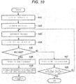
- FIG. 10 is a flowchart for explaining the operation of the non-discharge state detection unit of the droplet dispensing apparatus according to the first embodiment.
- the droplet dispensing apparatus 1 includes a main body 1A having a rectangular flat baseplate 3 and a mounting module 5.
- a microplate 4 which may also be referred to as a receiving unit, a multiwell plate, or a microwell plate in some contexts, has 96 wells into which a solution can be dispensed. Microplates having 96 wells are commonly used in a biochemical research and clinical examination. However, the microplate 4 is not limited to having 96 wells and may have any other number of wells, such as 384 wells, 1536 wells, 3456 wells, or 6144 wells.
- the microplate 4 is disposed at the center position of the baseplate 3 and can be secured to and detached from a plate attachment portion 3a of the baseplate 3.
- the ends of each of the X-direction guide rails 6a and 6b are fixed to fixing bases 7a and 7b protruding on the microplate 4.
- a Y-direction guide rail 8 extending in a Y-direction is installed between the X-direction guide rails 6a and 6b. Both ends of the Y-direction guide rail 8 are fixed to X-direction moving bases 9 which can slide in the X-direction along the X-direction guide rails 6a and 6b, respectively.
- a Y-direction moving base 10 is provided, on which the mounting module 5 is movable in the Y-direction along the Y-direction guide rail 8.
- the mounting module 5 is mounted on the Y-direction moving base 10.
- the droplet ejecting apparatus 2, which is a droplet ejecting unit, is fixed to the mounting module 5.
- the droplet ejecting apparatus 2 can move to any position in X and Y directions, which are orthogonal to each other in this instance, by the combination of a movement of the Y-direction moving base 10 along the Y-direction guide rail 8 in the Y-direction and a movement of the X-direction moving bases 9 along the X-direction guide rails 6a and 6b in the X-direction.
- the droplet ejecting apparatus 2 may be detached from and attached to the mounting module 5.
- the droplet ejecting apparatus 2 has a flat base plate 21. As shown in FIG. 2 , on a surface of the base plate 21 eight solution holding containers 22 are aligned in a row in the Y-direction. In some embodiments, the base plate 21 may have more or less than eight solution holding containers 22.
- the solution holding container 22 is a bottomed cylindrical container and an upper side is open as shown in FIG. 4 . On the bottom surface of the base plate 21, a cylindrical recessed portion 21 a is formed at a position corresponding to each solution holding container 22. The bottom of the solution holding container 22 is adhesively fixed to the recessed portion 21a.
- a solution outlet opening 22a (referred simply to as an opening hereinafter), through which is solution is ejected, is formed at the center position.
- An opening area of a top opening 22b of the solution holding container 22 is larger than an opening area of the opening 22a.
- an electrical mounting board 23 is provided at each of the solution holding containers 22 on the back side of the base plate 21.
- the electrical mounting board 23 is a rectangular flat plate.
- a rectangular recessed portion 21b for mounting the electrical mounting board 23 and a droplet ejection opening 21d communicating with the recessed portion 21b are formed on the back side of the base plate 21. Circumference of the recessed portion 21b extends from the solution holding container 22 towards an end of the base plate 21 (an upper end in FIG. 3 and a right end in FIG. 3 ).
- a portion of the recessed portion 21b overlaps with the solution holding container 22.
- the electrical mounting board 23 is adhesively fixed to the recessed portion 21b.
- an electrical mounting board wiring 24 is patterned on the side opposite to the recessed portion 21b.
- Three wiring patterns 24a, 24b, and 24c respectively connected to a terminal portion 131 of a lower electrode 131 and two terminal portions 133c of an upper electrode 133 are formed in the electrical mounting board wiring 24.
- An input signal control terminal 25 for receiving an external control signal is formed at one end of the electrical mounting board wiring 24.
- An electrode terminal connector 26 is provided at the other end of the electrical mounting board wiring 24. The electrode terminal connector 26 electrically connects the lower electrode terminal portion 131c and the upper electrode terminal portion 133c formed in the droplet ejection array 27 shown in FIG. 5 .
- the droplet ejection opening 21d is provided in the base plate 21, the droplet ejection opening 21d is provided. As shown in FIG. 3 , the droplet ejection opening 21d is a rectangular through-hole, and is formed at a position overlapping the recessed portion 21 a on the back side of the base plate 21.
- the droplet ejection array 27 shown in FIG. 5 is adhesively fixed to the lower surface of the solution holding container 22 so as to cover the opening 22a of the solution holding container 22.
- the droplet ejection array 27 is disposed at a position corresponding to the droplet ejection opening 21d of the base plate 21.
- the droplet ejection array 27 is formed by stacking a nozzle plate 100 and a pressure chamber structure 200.
- the nozzle plate 100 includes a nozzle 110 for discharging liquid, a diaphragm 120, a driving element 130, a protective film 150, and a liquid repelling film 160.
- An actuator 170 is formed with the diaphragm 120 and the driving element 130.
- the actuator 170 may be a piezoelectric element made of a lead-free material containing no lead component, or a piezoelectric element made of lead-containing material.
- the droplet ejection array 27 has a nozzle group in which a plurality of nozzles is arranged in a X-Y plane that is parallel to the X-direction and the Y-direction.
- three nozzles 110 are disposed in a vertical direction (also referred to as a first direction)
- four nozzles 110 are disposed in a horizontal direction (also referred to as a second direction)
- one set of twelve nozzles 110 arranged in 3 ⁇ 4 rows and columns is defined as a nozzle group. That is, in the example embodiment described herein, as shown in FIG. 5 , a plurality of nozzles 110 is disposed in each of the first direction and the second direction.
- the terminal portion 131c of the lower electrode 131 is spaced from the nozzle group in the first direction, and the terminal portion 131c and other terminal portions 131c for other nozzle groups are aligned in the second direction.
- twelve nozzles in one nozzle group are disposed at a position corresponding to one opening 22a of one of the eight solution holding containers 22.
- the twelve nozzles 110 of one nozzle group are disposed only within one well opening 4b of the microplate 4.
- the diaphragm 120 is formed integrally with the pressure chamber structure 200, for example.
- the driving element 130 is formed for each nozzle 110.
- the driving element 130 has an annular shape surrounding the nozzle 110.
- the shape of the driving element 130 is not limited, and may be, for example, a C-shape in which a part of a circular ring is cut out.
- the diaphragm 120 deforms in the thickness direction by the action of the planar driving element 130.
- the droplet ejecting apparatus 2 discharges the solution supplied to the nozzle 110 due to the pressure change occurring in the pressure chamber 210 of the pressure chamber structure 200 caused by the deformation of the diaphragm 120.
- the main body 1A of the droplet dispensing apparatus 1 includes a non-discharge state detection unit 231 shown in FIG. 7 .
- the non-discharge state detection unit 231 includes a weight measuring device 230, which may be referred to as a scale, weight sensor, or simply a sensor, that measures the weight of the microplate 4, using a crystal oscillator, for example.
- the weight measuring device 230 is connected to a controller 232, including a processor (not shown), which controls the operation of the droplet ejecting apparatus 2 or the overall operation of the droplet dispensing apparatus 1. Detection data from the weight measuring device 230 is input to the controller 232.
- a display unit 233 such as a monitor, for example, is connected to the controller 232, and a D curve detection unit 234 that detects a drying reduction curve D, which corresponds to a drying reduction as a function of time, is built therein.
- the controller 232 detects a weight reduction of the droplet due to drying, which corresponds to a correction value in reference to a drying reduction curve D to an initial measured value of the weight (w) of the microplate 4.
- the weight measuring device 230 measures an initial weight of the microplate 4 at a beginning of a dropping process and a final weight (w) of the microplate 4 after droplets are dropped on the microplate 4 for a predetermined time, and displays the measured initial weight and the final weight (w) on the display unit 233 as necessary.
- the controller 232 determines that some of the nozzles 110 in the nozzle group are not discharging, when a difference between the measured final weight (w) and the measured initial weight of the microplate 4 is smaller than an expected weight reduction of the droplets due to drying during the droplet dropping process.
- the controller 232 displays information of the droplet dispensing apparatus 1 on the display unit 233 such as a monitor, and abort further droplet dropping processing.
- the controller 232 does not detect any nozzle 110 that is not discharging, the controller 232 continues further droplet dropping processing until a predetermined number of droplets are dropped into all wells.
- the droplet ejecting apparatus 2 is mounted on the mounting module 5.
- a predetermined amount of solution is supplied to the solution holding container 22 from the top opening 22b of the solution holding container 22 by a pipette or the like (not shown).
- the solution is held on the inner surface of the solution holding container 22.
- the opening 22a at the bottom of the solution holding container 22 communicates with the droplet ejection array 27.
- the solution held in the solution holding container 22 flows into each pressure chamber 210 of the droplet ejection array 27 through the opening 22a.
- a voltage control signal that is input to the input signal control terminal 25 is transmitted from the electrode terminal connector 26 to the terminal portion 131c of the lower electrode 131 and the terminal portion 133c of the upper electrode 133.
- the diaphragm 120 is deformed to change the volume of the pressure chamber 210, and thus the solution is discharged as solution droplets from the nozzle 110 of the droplet ejection array 27.
- solution droplets are simultaneously dropped from the twelve nozzles 110 to one well opening 4b of the microplate 4.
- a predetermined amount of liquid is dropped to each well opening 4b of the microplate 4 from the nozzle 110.
- An amount of liquid that is dropped is controlled by a number of repetitions of one-droplet dropping from each nozzle 110, and thus it is possible to control dropping of a liquid to each well opening 4b in the order of picoliter (pL) to microliter ( ⁇ L).
- the controller 232 performs the control of the non-discharge state detection unit 231 shown in the flowchart of FIG. 10 .
- the controller 232 performs an initial measurement control (Act1).
- an initial weight w0 of a microplate 4 is measured at a time t1 immediately after a first dropping operation starts.
- the controller 232 acquires the initial weight w0 of the microplate 4 measured by the weight measuring device 230 at time t1 .
- a solid line e indicates the expected weight w1 of the microplate 4 after a predetermined number of droplets are dropped.
- FIG. 8 depicts weights of the microplate 4 at times t1, t2, and t3 without a liquid reduction due to drying.
- FIG. 9 depicts time variation of the weight of the microplate 4 in consideration of the liquid reduction due to drying after a predetermined time from the initial measurement time at t1.
- the controller 232 performs first dropping operation control at the time t1 immediately after the first dropping operation starts.
- the controller 232 acquires the initial weight w0 of the microplate 4 measured by the weight measuring device 230.
- the controller 232 detects a liquid reduction caused by drying of the microplate 4, before the second dropping operation starts at a time t2 (Act2).
- the controller 232 acquires weights w (w01, w02, w03 %) of the microplate 4 at each of a plurality of set times (t11, t12, t13 ...) from the initial measurement time t1.
- the controller 232 calculates a characteristic curve connecting w0, w01, w02, w03 ..., and defines the characteristic curve as a drying reduction curve D.
- the controller 232 proceeds to the discharge process in Act3.
- the controller 232 performs the second dropping operation control at time t2 in FIG. 9 .
- the solid line e indicates the expected weight w1 of the microplate 4 after a predetermined number of droplets are dropped.
- the weight w of the microplate 4 decreases due to drying. Therefore, at the time of the second dropping operation, the weight of the liquid in the microplate 4 is w21 ⁇ w0 (w01, w02, and w03).
- the weight w21 is determined along the drying reduction curve D.
- the controller 232 performs the second dropping operation control for the microplate 4 having the weight w21. Therefore, the controller 232 predicts or estimates that the weight w22 after the expected weight reduction due to drying at time point t2 will be less than w1.
- the weight measuring device 230 measures a final weight w31 of the microplate 4, and the controller 232 acquires this the measured final weight w31 (Act4).
- the controller 232 determines whether or not w31 is equal to the predicted weight determined by reference to the drying reduction curve D.
- the controller 232 determines that some of the nozzles 110 in the nozzle group are not discharging as intended (Act6).
- the controller 232 determines that all nozzles 110 in the nozzle group are discharging as intended (Act7). After Act6, the controller 232 proceeds to Act8, displays information indicating a non-discharge state, for example, "Error/Stop" on the display unit 233, and aborts further droplet dropping processes. After Act7, the controller 232 proceeds to Act9 and continues further droplet dropping processes until a predetermined number of droplets are dropped to all wells (Act3). When it is confirmed that the predetermined number of droplets has been dropped to all wells (Act10), the controller 232 completes the process.
- a non-discharge state detection unit 231 is driven at the time of a dropping operation.
- the controller 232 by the non-discharge state detection unit 231, detects weight reduction of droplets due to drying based on an initial weight of the microplate 4 measured by the weight measuring device 230.
- the controller 232 determines that some of the nozzle 110 in the nozzle group are not charging as intended.
- the controller 232 can detect a discharge failure in which some of the nozzles 110 in a nozzle group are not discharging during a dropping process.
- a discharge failure such as clogging, in which some of the nozzles 110 in the nozzle group are not discharging as intended.
- the controller 232 can quickly stop further solution dropping from the nozzle 110.
- the controller 232 can stop the dropping of liquid at an early stage when a discharge failure occurs, which contributes to reduction of waste in a dose-response or the like, and early error detection in an evaluation results of drug performance.
- a piezoelectric element may be made of a lead-free material that has lower piezoelectric characteristics than a piezoelectric element including a lead component, for example, PZT (Pb(Zr, Ti)O 3 : lead titanate zirconate). Therefore, in the case of the piezoelectric element made of a lead-free material, the amount of displacement of the diaphragm 120 during driving is smaller than that of the piezoelectric element made of PZT, so that the amount of liquid per drop is small.
- PZT Pb(Zr, Ti)O 3 : lead titanate zirconate
- a plurality of nozzles 110 (12 nozzles arranged in 3 ⁇ 4 rows and columns) in one nozzle group for one well opening 4b is provided.
- FIG. 11 is a schematic diagram of a non-discharge state detection unit of a droplet dispensing apparatus according to a second embodiment.
- FIG. 12 is a diagram for explaining an ideal state in which there is no drying from a microplate of the droplet dispensing apparatus.
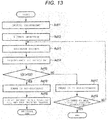
- FIG. 13 is a flowchart for explaining the operation of the non-discharge state detection unit of the droplet dispensing apparatus according to the second embodiment.
- the non-discharge state detection unit 231 of the droplet dispensing apparatus 1 according to the first embodiment is modified as follows.
- the same reference numerals are used for the components that are substantially the same as those of the first embodiment, and the detailed description of repeated components may be omitted.
- a non-discharge state detection unit 241 detects a discharge failure by measuring of a microplate 4 by the weight measuring device 230.
- a non-discharge state detection unit 241 includes a scanner 240, which may be referred to as a transparency sensor or simply a sensor, that detects the presence or absence of droplets discharged from the nozzles 110 in the nozzle group based on the measured or otherwise detected transparency of the microplate 4.
- the scanner 240 is formed of, for example, a CMOS sensor.
- the scanner 240 is connected to a controller 242 which controls the operation of the droplet ejecting apparatus 2 or the overall operation of the droplet dispensing apparatus 1.
- the detection data from the scanner 240 is input to the controller 242.
- a display unit 243 such as a monitor is connected to the controller 242, and a transparency detection unit 244 that measures the transparency of the microplate 4 is built therein.
- the controller 242 detects a decrease or otherwise a change in transparency (v) of droplets due to drying from the initial transparency (v) of the microplate 4.
- the scanner 240 measures initial transparency of the microplate 4 at a beginning of a dropping process and a final transparency (v) of the microplate 4 after droplets are dropped on the microplate 4 and the measured transparency (v) of the microplate 4 for a predetermined time, and displays the measured initial transparency and the final transparency (v) on the display unit 243 as necessary.
- the controller 242 determines that some of the nozzles 110 in the nozzle group are not discharging, when a difference between the measured final transparency (v) and the measured initial transparency of the microplate 4 is smaller than an expected transparency reduction of the droplets due to drying during the droplet dropping process.
- the controller 242 displays information of the droplet dispensing apparatus 1 on the display unit 233 such as a monitor, and abort further droplet dropping processing.
- the controller 242 does not detect any nozzle 110 that is not discharging, the controller 242 continues further droplet dropping processing.
- the controller 242 performs the control of the non-discharge state detection unit 241 shown in the flowchart of FIG. 13 .
- the controller 242 performs initial measurement control (Act11).
- the initial measurement control shown in FIG. 12
- an initial transparency of a microplate 4 is measured at a time t1 immediately after a first dropping operation starts.
- the controller 242 acquires the final transparency v0 of the microplate 4 measured by the scanner 240.
- the controller 242 performs a second dropping operation control at a time t2.
- the solid line e indicates the predicted transparency v1 of the microplate 4 after expected transparency reduction due to drying.
- the actual curve in consideration of the liquid reduction amount due to the dry state of the microplate 4 after a lapse of a predetermined time from the above initial measurement time shows characteristics similar to those in the first embodiment. That is, in the initial measurement control, shown in FIG. 12 , an initial transparency v0 of a microplate 4 is measured at a time t1 immediately after a first dropping operation starts. The controller 242 acquires the final transparency (v) of the microplate 4 measured by the scanner 240.
- the controller 242 detects a liquid reduction caused by drying of the microplate 4, before the second dropping operation starts at a time t2 (Act12).
- the controller 242 acquires transparencies (v) of the microplate 4 at a plurality of set times (t11, t12, t13 ...) from the initial measurement time t1 at which the scanner 240 performs the initial transparency measurement.
- the controller 242 calculates a characteristic curve connecting the transparencies (v) measured at the plurality of set times, and defines the characteristic curve as a drying reduction curve D.
- the controller 242 proceeds to the discharge process in Act13.
- the controller 242 performs the second dropping operation control at time t2 in FIG. 12 .
- the solid line e indicates the expected transparency (v) of the microplate 4 after a predetermined number of droplets are dropped.
- the transparency (v) of the microplate 4 decreases due to drying.
- the transparency (v) is determined along the drying reduction curve D.
- the controller 242 performs the second dropping operation control for the microplate 4 having the transparency (v). Therefore, the controller 242 predicts that the transparency v22 of the microplate 4 at time t2 is less than v1.
- the controller 242 acquires the final transparency v31 of the microplate 4 measured by the scanner 240 (Act14).
- the controller 242 determines whether or not v31 is equal to the predicted transparency determined in reference to the drying reduction curve D.
- the controller 242 determines that some of the nozzles 110 in the nozzle group are not discharging as intended (Act16). If the v31 is equal to the predicted transparency determined in reference the drying reduction curve D, the controller 242 determines that all nozzles 110 in the nozzle group are charging as intended (Act17).
- the controller 242 proceeds to Act18, displays information indicating a non-discharge state, for example, "Error/Stop" on the display unit 233, and aborts further droplet dropping processes.
- the controller 242 proceeds to Act19 and continues further droplet dropping processes until a predetermined number of droplets are dropped to all wells (Act13). When it is confirmed that the predetermined number of droplets has been dropped to all wells (Act10) the controller 242 completes the process.
- the controller 242 acquires weight reduction of droplets due drying based on an initial transparency (v) of the microplate 4 measured by the scanner 240.
- the controller 242 determines that some of the nozzles 110 in the nozzle group are not discharging as intended, when the transparency (v) of the microplate 4 measured by the scanner 240 is smaller than a predicted transparency (v) of the microplate 4 after an expected transparency reduction due to drying of droplets, which corresponds to a correction value in reference to the drying reduction curve D), during a droplet dropping process.
- the controller 242 can detect a discharge failure in which some of the nozzles 110 in a nozzle group are not discharging during a dropping process.
- the controller 242 can detect a discharge failure, such as clogging, in which some of the nozzles 110 in the nozzle group are not discharging as intended.
- a discharge failure such as clogging
- the controller 242 can quickly stop further solution dropping from the nozzle 110.
- the controller 242 can stop the dropping of liquid at an early stage when a discharge failure occurs, which contributes to reduction of waste in a dose-response or the like, and early error detection in an evaluation results of drug performance. As a result, it is possible to provide a droplet dispensing apparatus which can provide more accurate evaluation results of drug performance. Furthermore, in the second embodiment, since the scanner 240 measures the transparency (v) of the microplate 4 by, the controller 242 can detect a discharge failure in individual nozzles 110 for each well-opening 4b of the microplate 4. Therefore, it is possible to more accurately detect a discharge failure in specific nozzles 110 in one nozzle group are not discharging.
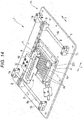
- FIG. 14 is a perspective view of a non-discharge state detection unit of a droplet dispensing apparatus according to a third embodiment.
- the droplet dispensing apparatus 1 according to the first embodiment is modified.
- the same reference numerals are used for the components that are substantially the same as those of the first embodiment, and the detailed description of repeated components may be omitted.
- a second droplet ejecting unit 251 in addition to the droplet ejection array 27 is provided.
- the second droplet ejecting unit 251 includes a support mechanism (not specifically depicted) which supports the droplet ejecting apparatus 2 so as to be movable to an arbitrary position in the X-Y direction separately from the droplet ejecting apparatus 2.
- the second droplet ejecting unit 251 includes, for example, a water tank (not specifically depicted).
- the second droplet ejecting unit 251 may further include a tank that contains the same liquid as that of the droplet ejection array 27.
- a solution e.g., water
- a solution is additionally discharged from the second droplet ejecting unit 251 to each well opening 4b of the microplate 4.
- the support mechanism of the second droplet ejecting unit 251 may be able to perform a parallel process of dispensing a droplet in parallel with or perpendicular to the droplet ejection array 27.
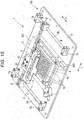
- FIG. 15 is a perspective view of is a perspective view of a non-discharge state detection unit of a droplet dispensing apparatus according to a fourth embodiment.
- the droplet dispensing apparatus 1 according to the first embodiment is modified.
- the same reference numerals are used for the components that are substantially the same as those of the first embodiment, and the detailed description of repeated components may be omitted.
- a sealed box component 261 that encloses the microplate 4 and a spraying device 262 spraying a humidifying solution within the sealed box component 261 are provided on the baseplate 3.
- the sealed box component 261 includes, for example, a frame portion having a highly rigid frame structure and a cover made of an elastic material for closing a space between the frame portions of each frame.
- the inside of the sealed box component 261 can be hermetically sealed by the frame portion and the cover.
- the spraying device 262 includes, for example, a water tank (not specifically depicted).
- the spraying device 262 may further include a tank that contains the same liquid as that of the liquid ejection array 27.
- the spraying device 262 is provided in the sealed box component 261, and sprays a drying prevention liquid inside of the sealed box component 261 for drying prevention.
- droplets for preventing drying are sprayed from the spraying device 262 inside of the sealed box component 261.
- the spraying device 262 may also be configured such that droplets for drying prevention are sprayed simultaneously with the start of the liquid dropping operation from the droplet ejection array 27.
- FIG. 16 is a longitudinal cross-sectional view of a microplate 4 according to a fifth embodiment.
- a lid member 271 made of an elastic material, such as rubber, is provided on the periphery of the opening of the well opening 4b.
- a notch 272 such as a slit is formed at the center position of the opening of the well opening 4b.
- a needle-like injection member 273 is provided with the droplet ejection array 27. At the tip end of the injection member 273, there is provided an actuator capable of injecting droplets of a pL order.
- the opening of the well opening 4b is blocked by the lid 271 in the standby state (when not in use). In this state, the notch 272 of the lid 271 is closed.
- the tip end of the injection member 273 is press-fitted into the notch 272 of the lid 271.
- the tip end of the injection member 273 opens the notch 272 of the lid member 271.
- the lid 271 elastically deforms to a state in which the peripheral portions on both sides of the notch 272 are pushed into the inside of the well opening 4b. Therefore, when the tip end of the injection member 273 is inserted to the inside of the well opening 4b, droplets are discharged from the tip end of the injection member 273.
- the injection member 273 When a specified number of droplets are discharged from the injection member 273, the injection member 273 is drawn out of the microplate 4. At this time, the lid 271 elastically returns to a state in which the peripheral portions on both sides of the notch 272 are closed. Therefore, the well opening 4b of the microplate 4 is closed by the lid 271. As a result, the inner space of the well opening 4b of the microplate 4 is maintained in an airtight state by the lid 271, so that evaporation of the droplet injected into the internal space of the well opening 4b of the microplate 4 is prevented.
Landscapes
- Chemical & Material Sciences (AREA)
- Health & Medical Sciences (AREA)
- General Health & Medical Sciences (AREA)
- Life Sciences & Earth Sciences (AREA)
- Analytical Chemistry (AREA)
- Biochemistry (AREA)
- Physics & Mathematics (AREA)
- General Physics & Mathematics (AREA)
- Immunology (AREA)
- Pathology (AREA)
- Clinical Laboratory Science (AREA)
- Chemical Kinetics & Catalysis (AREA)
- Automatic Analysis And Handling Materials Therefor (AREA)
- Coating Apparatus (AREA)
- Ink Jet (AREA)
Applications Claiming Priority (1)
| Application Number | Priority Date | Filing Date | Title |
|---|---|---|---|
| JP2017059796A JP2018163016A (ja) | 2017-03-24 | 2017-03-24 | 液滴分注装置 |
Publications (3)
| Publication Number | Publication Date |
|---|---|
| EP3378563A2 true EP3378563A2 (fr) | 2018-09-26 |
| EP3378563A3 EP3378563A3 (fr) | 2018-10-17 |
| EP3378563B1 EP3378563B1 (fr) | 2020-04-22 |
Family
ID=61526724
Family Applications (1)
| Application Number | Title | Priority Date | Filing Date |
|---|---|---|---|
| EP18159404.5A Not-in-force EP3378563B1 (fr) | 2017-03-24 | 2018-03-01 | Appareil de distribution de gouttelettes |
Country Status (4)
| Country | Link |
|---|---|
| US (1) | US20180272335A1 (fr) |
| EP (1) | EP3378563B1 (fr) |
| JP (1) | JP2018163016A (fr) |
| CN (1) | CN108621560B (fr) |
Cited By (1)
| Publication number | Priority date | Publication date | Assignee | Title |
|---|---|---|---|---|
| CN109353121A (zh) * | 2018-09-28 | 2019-02-19 | 共享智能铸造产业创新中心有限公司 | 基于喷墨式打印头的喷墨衰减量的计算方法和装置 |
Families Citing this family (10)
| Publication number | Priority date | Publication date | Assignee | Title |
|---|---|---|---|---|
| JP7019303B2 (ja) | 2017-03-24 | 2022-02-15 | 東芝テック株式会社 | 液滴分注装置 |
| JP7019344B2 (ja) | 2017-08-22 | 2022-02-15 | 東芝テック株式会社 | 薬液滴下装置及び薬液吐出装置 |
| JP6925908B2 (ja) | 2017-08-22 | 2021-08-25 | 東芝テック株式会社 | 薬液滴下装置 |
| US20190262829A1 (en) * | 2018-02-28 | 2019-08-29 | Volta Labs, Inc. | Directing Motion of Droplets Using Differential Wetting |
| JP2019184495A (ja) | 2018-04-13 | 2019-10-24 | 東芝テック株式会社 | 液滴分注装置 |
| CN110596411B (zh) * | 2019-10-22 | 2020-11-06 | 威海迈维特智能识别技术有限公司 | 一种微流控芯片点样机及点样方法 |
| JP7458894B2 (ja) * | 2020-05-15 | 2024-04-01 | 東芝テック株式会社 | 液滴分注装置 |
| JP2024160497A (ja) * | 2023-05-01 | 2024-11-14 | 船井電機株式会社 | 液滴分注装置及び制御方法 |
| DE102024102936A1 (de) | 2024-02-01 | 2025-08-07 | Fraunhofer-Gesellschaft zur Förderung der angewandten Forschung eingetragener Verein | System und Verfahren zur Volumenbestimmung in Mikrotiterplatten |
| CN119238966B (zh) * | 2024-12-04 | 2025-04-29 | 广东峰华卓立科技股份有限公司 | 一种粘结剂喷射3d打印的喷墨状态检测设备及方法 |
Family Cites Families (18)
| Publication number | Priority date | Publication date | Assignee | Title |
|---|---|---|---|---|
| DE2937476A1 (de) * | 1979-09-17 | 1981-04-02 | Agfa-Gevaert Ag, 5090 Leverkusen | Vorrichtung zur messung der oberflaechenspannung |
| US6235242B1 (en) * | 1997-09-25 | 2001-05-22 | Robert A. Small | Sample size characterization technique and apparatus for liquid analysis |
| US6998230B1 (en) * | 2000-04-26 | 2006-02-14 | Agilent Technologies, Inc. | Array fabrication with drop detection |
| JP3621041B2 (ja) * | 2000-11-06 | 2005-02-16 | 日本碍子株式会社 | 液滴吐出装置 |
| JP2003322630A (ja) * | 2002-05-01 | 2003-11-14 | Seiko Epson Corp | バイオセンサ、バイオセンシングシステム、及びバイオセンシング方法 |
| SE0300329D0 (sv) * | 2003-02-07 | 2003-02-07 | Jenser Technology Ab | Förfarande och instrument för att mäta ytspänning |
| JP2004361234A (ja) * | 2003-06-04 | 2004-12-24 | Seiko Epson Corp | 液滴吐出評価試験装置 |
| JP2005114432A (ja) * | 2003-10-03 | 2005-04-28 | Canon Inc | 液体吐出ヘッドおよび該液体吐出ヘッドを備えた液体吐出装置 |
| JP4441336B2 (ja) * | 2004-06-11 | 2010-03-31 | 日本碍子株式会社 | マイクロアレイの製造方法 |
| JP2007107933A (ja) * | 2005-10-11 | 2007-04-26 | Sharp Corp | 液滴量測定方法、及び液滴量測定装置 |
| US20080261326A1 (en) * | 2007-04-23 | 2008-10-23 | Christie Dudenhoefer | Drop-on-demand manufacturing of diagnostic test strips |
| KR101339987B1 (ko) * | 2007-12-24 | 2013-12-10 | 삼성전자주식회사 | 액적 질량편차 측정장치와 이의 액적 질량편차 측정방법과이를 이용하는 패턴형성 시스템 및 이를 이용하는 패턴형성시스템의 제어방법 |
| CN201619301U (zh) * | 2009-12-31 | 2010-11-03 | 杭州宏华数码科技股份有限公司 | 具有调温调湿功能的墨滴观测仪 |
| CN103429348B (zh) * | 2011-01-21 | 2016-03-09 | 拜奥-多特公司 | 具有纵向变换器和可替换毛细管的压电分配器 |
| JP2013044530A (ja) * | 2011-08-22 | 2013-03-04 | Hitachi High-Technologies Corp | 分注装置 |
| KR20190123811A (ko) * | 2012-12-27 | 2019-11-01 | 카티바, 인크. | 정밀 공차 내로 유체를 증착하기 위한 인쇄 잉크 부피 제어를 위한 기법 |
| JP2017015466A (ja) * | 2015-06-29 | 2017-01-19 | 東芝テック株式会社 | 液滴噴射装置 |
| CN106004044B (zh) * | 2016-05-11 | 2017-12-22 | 京东方科技集团股份有限公司 | 墨水测量系统及打印设备 |
-
2017
- 2017-03-24 JP JP2017059796A patent/JP2018163016A/ja active Pending
-
2018
- 2018-02-06 US US15/890,070 patent/US20180272335A1/en not_active Abandoned
- 2018-03-01 EP EP18159404.5A patent/EP3378563B1/fr not_active Not-in-force
- 2018-03-05 CN CN201810177923.2A patent/CN108621560B/zh not_active Expired - Fee Related
Non-Patent Citations (1)
| Title |
|---|
| None |
Cited By (2)
| Publication number | Priority date | Publication date | Assignee | Title |
|---|---|---|---|---|
| CN109353121A (zh) * | 2018-09-28 | 2019-02-19 | 共享智能铸造产业创新中心有限公司 | 基于喷墨式打印头的喷墨衰减量的计算方法和装置 |
| CN109353121B (zh) * | 2018-09-28 | 2020-07-28 | 共享智能铸造产业创新中心有限公司 | 基于喷墨式打印头的喷墨衰减量的计算方法和装置 |
Also Published As
| Publication number | Publication date |
|---|---|
| JP2018163016A (ja) | 2018-10-18 |
| CN108621560B (zh) | 2020-04-28 |
| EP3378563B1 (fr) | 2020-04-22 |
| CN108621560A (zh) | 2018-10-09 |
| EP3378563A3 (fr) | 2018-10-17 |
| US20180272335A1 (en) | 2018-09-27 |
Similar Documents
| Publication | Publication Date | Title |
|---|---|---|
| EP3378563B1 (fr) | Appareil de distribution de gouttelettes | |
| US11213813B2 (en) | Droplet dispensing apparatus | |
| EP3378562A1 (fr) | Appareil de distribution de gouttelettes | |
| US11879766B2 (en) | Droplet dispensing apparatus | |
| EP3378560A1 (fr) | Appareil de distribution de gouttelettes | |
| EP3552705A1 (fr) | Appareil de distribution de gouttelettes | |
| US20100261611A1 (en) | Assay system and method | |
| KR20200118063A (ko) | 자동 부피 측정 장치 | |
| EP3447454A1 (fr) | Appareil de distribution de liquides | |
| EP3446783A1 (fr) | Dispositif et procédé de décharge de liquide | |
| US10682874B2 (en) | Droplet dispensing apparatus | |
| CN109420572B (zh) | 药液滴下装置及药液滴下系统 | |
| US20130099023A1 (en) | Fluid ejection device | |
| US7960183B2 (en) | Biochip manufacturing method and biochip manufacturing device | |
| US20240383252A1 (en) | Droplet dispensing device, sensor plate, and droplet detection method |
Legal Events
| Date | Code | Title | Description |
|---|---|---|---|
| PUAI | Public reference made under article 153(3) epc to a published international application that has entered the european phase |
Free format text: ORIGINAL CODE: 0009012 |
|
| STAA | Information on the status of an ep patent application or granted ep patent |
Free format text: STATUS: THE APPLICATION HAS BEEN PUBLISHED |
|
| PUAL | Search report despatched |
Free format text: ORIGINAL CODE: 0009013 |
|
| AK | Designated contracting states |
Kind code of ref document: A2 Designated state(s): AL AT BE BG CH CY CZ DE DK EE ES FI FR GB GR HR HU IE IS IT LI LT LU LV MC MK MT NL NO PL PT RO RS SE SI SK SM TR |
|
| AX | Request for extension of the european patent |
Extension state: BA ME |
|
| AK | Designated contracting states |
Kind code of ref document: A3 Designated state(s): AL AT BE BG CH CY CZ DE DK EE ES FI FR GB GR HR HU IE IS IT LI LT LU LV MC MK MT NL NO PL PT RO RS SE SI SK SM TR |
|
| AX | Request for extension of the european patent |
Extension state: BA ME |
|
| RIC1 | Information provided on ipc code assigned before grant |
Ipc: B01L 3/02 20060101AFI20180913BHEP Ipc: G01N 35/10 20060101ALN20180913BHEP |
|
| STAA | Information on the status of an ep patent application or granted ep patent |
Free format text: STATUS: REQUEST FOR EXAMINATION WAS MADE |
|
| STAA | Information on the status of an ep patent application or granted ep patent |
Free format text: STATUS: EXAMINATION IS IN PROGRESS |
|
| 17P | Request for examination filed |
Effective date: 20190417 |
|
| RBV | Designated contracting states (corrected) |
Designated state(s): AL AT BE BG CH CY CZ DE DK EE ES FI FR GB GR HR HU IE IS IT LI LT LU LV MC MK MT NL NO PL PT RO RS SE SI SK SM TR |
|
| 17Q | First examination report despatched |
Effective date: 20190513 |
|
| GRAP | Despatch of communication of intention to grant a patent |
Free format text: ORIGINAL CODE: EPIDOSNIGR1 |
|
| STAA | Information on the status of an ep patent application or granted ep patent |
Free format text: STATUS: GRANT OF PATENT IS INTENDED |
|
| RIC1 | Information provided on ipc code assigned before grant |
Ipc: G01N 35/10 20060101ALI20190924BHEP Ipc: B01L 3/02 20060101AFI20190924BHEP Ipc: G01N 35/04 20060101ALN20190924BHEP |
|
| INTG | Intention to grant announced |
Effective date: 20191008 |
|
| RIN1 | Information on inventor provided before grant (corrected) |
Inventor name: KAIHO, SATOSHI Inventor name: KUSUNOKI, RYUTARO Inventor name: YOKOYAMA, SHUHEI Inventor name: SHIMIZU, SEIYA Inventor name: HIGUCHI, MASAAKI |
|
| GRAS | Grant fee paid |
Free format text: ORIGINAL CODE: EPIDOSNIGR3 |
|
| GRAA | (expected) grant |
Free format text: ORIGINAL CODE: 0009210 |
|
| STAA | Information on the status of an ep patent application or granted ep patent |
Free format text: STATUS: THE PATENT HAS BEEN GRANTED |
|
| AK | Designated contracting states |
Kind code of ref document: B1 Designated state(s): AL AT BE BG CH CY CZ DE DK EE ES FI FR GB GR HR HU IE IS IT LI LT LU LV MC MK MT NL NO PL PT RO RS SE SI SK SM TR |
|
| REG | Reference to a national code |
Ref country code: CH Ref legal event code: EP |
|
| REG | Reference to a national code |
Ref country code: IE Ref legal event code: FG4D |
|
| REG | Reference to a national code |
Ref country code: DE Ref legal event code: R096 Ref document number: 602018003864 Country of ref document: DE |
|
| REG | Reference to a national code |
Ref country code: AT Ref legal event code: REF Ref document number: 1259367 Country of ref document: AT Kind code of ref document: T Effective date: 20200515 |
|
| REG | Reference to a national code |
Ref country code: LT Ref legal event code: MG4D |
|
| REG | Reference to a national code |
Ref country code: NL Ref legal event code: MP Effective date: 20200422 |
|
| PG25 | Lapsed in a contracting state [announced via postgrant information from national office to epo] |
Ref country code: PT Free format text: LAPSE BECAUSE OF FAILURE TO SUBMIT A TRANSLATION OF THE DESCRIPTION OR TO PAY THE FEE WITHIN THE PRESCRIBED TIME-LIMIT Effective date: 20200824 Ref country code: NO Free format text: LAPSE BECAUSE OF FAILURE TO SUBMIT A TRANSLATION OF THE DESCRIPTION OR TO PAY THE FEE WITHIN THE PRESCRIBED TIME-LIMIT Effective date: 20200722 Ref country code: FI Free format text: LAPSE BECAUSE OF FAILURE TO SUBMIT A TRANSLATION OF THE DESCRIPTION OR TO PAY THE FEE WITHIN THE PRESCRIBED TIME-LIMIT Effective date: 20200422 Ref country code: LT Free format text: LAPSE BECAUSE OF FAILURE TO SUBMIT A TRANSLATION OF THE DESCRIPTION OR TO PAY THE FEE WITHIN THE PRESCRIBED TIME-LIMIT Effective date: 20200422 Ref country code: NL Free format text: LAPSE BECAUSE OF FAILURE TO SUBMIT A TRANSLATION OF THE DESCRIPTION OR TO PAY THE FEE WITHIN THE PRESCRIBED TIME-LIMIT Effective date: 20200422 Ref country code: IS Free format text: LAPSE BECAUSE OF FAILURE TO SUBMIT A TRANSLATION OF THE DESCRIPTION OR TO PAY THE FEE WITHIN THE PRESCRIBED TIME-LIMIT Effective date: 20200822 Ref country code: SE Free format text: LAPSE BECAUSE OF FAILURE TO SUBMIT A TRANSLATION OF THE DESCRIPTION OR TO PAY THE FEE WITHIN THE PRESCRIBED TIME-LIMIT Effective date: 20200422 Ref country code: GR Free format text: LAPSE BECAUSE OF FAILURE TO SUBMIT A TRANSLATION OF THE DESCRIPTION OR TO PAY THE FEE WITHIN THE PRESCRIBED TIME-LIMIT Effective date: 20200723 |
|
| REG | Reference to a national code |
Ref country code: AT Ref legal event code: MK05 Ref document number: 1259367 Country of ref document: AT Kind code of ref document: T Effective date: 20200422 |
|
| PG25 | Lapsed in a contracting state [announced via postgrant information from national office to epo] |
Ref country code: RS Free format text: LAPSE BECAUSE OF FAILURE TO SUBMIT A TRANSLATION OF THE DESCRIPTION OR TO PAY THE FEE WITHIN THE PRESCRIBED TIME-LIMIT Effective date: 20200422 Ref country code: BG Free format text: LAPSE BECAUSE OF FAILURE TO SUBMIT A TRANSLATION OF THE DESCRIPTION OR TO PAY THE FEE WITHIN THE PRESCRIBED TIME-LIMIT Effective date: 20200722 Ref country code: LV Free format text: LAPSE BECAUSE OF FAILURE TO SUBMIT A TRANSLATION OF THE DESCRIPTION OR TO PAY THE FEE WITHIN THE PRESCRIBED TIME-LIMIT Effective date: 20200422 Ref country code: HR Free format text: LAPSE BECAUSE OF FAILURE TO SUBMIT A TRANSLATION OF THE DESCRIPTION OR TO PAY THE FEE WITHIN THE PRESCRIBED TIME-LIMIT Effective date: 20200422 |
|
| PG25 | Lapsed in a contracting state [announced via postgrant information from national office to epo] |
Ref country code: AL Free format text: LAPSE BECAUSE OF FAILURE TO SUBMIT A TRANSLATION OF THE DESCRIPTION OR TO PAY THE FEE WITHIN THE PRESCRIBED TIME-LIMIT Effective date: 20200422 |
|
| REG | Reference to a national code |
Ref country code: DE Ref legal event code: R097 Ref document number: 602018003864 Country of ref document: DE |
|
| PG25 | Lapsed in a contracting state [announced via postgrant information from national office to epo] |
Ref country code: ES Free format text: LAPSE BECAUSE OF FAILURE TO SUBMIT A TRANSLATION OF THE DESCRIPTION OR TO PAY THE FEE WITHIN THE PRESCRIBED TIME-LIMIT Effective date: 20200422 Ref country code: AT Free format text: LAPSE BECAUSE OF FAILURE TO SUBMIT A TRANSLATION OF THE DESCRIPTION OR TO PAY THE FEE WITHIN THE PRESCRIBED TIME-LIMIT Effective date: 20200422 Ref country code: DK Free format text: LAPSE BECAUSE OF FAILURE TO SUBMIT A TRANSLATION OF THE DESCRIPTION OR TO PAY THE FEE WITHIN THE PRESCRIBED TIME-LIMIT Effective date: 20200422 Ref country code: CZ Free format text: LAPSE BECAUSE OF FAILURE TO SUBMIT A TRANSLATION OF THE DESCRIPTION OR TO PAY THE FEE WITHIN THE PRESCRIBED TIME-LIMIT Effective date: 20200422 Ref country code: RO Free format text: LAPSE BECAUSE OF FAILURE TO SUBMIT A TRANSLATION OF THE DESCRIPTION OR TO PAY THE FEE WITHIN THE PRESCRIBED TIME-LIMIT Effective date: 20200422 Ref country code: IT Free format text: LAPSE BECAUSE OF FAILURE TO SUBMIT A TRANSLATION OF THE DESCRIPTION OR TO PAY THE FEE WITHIN THE PRESCRIBED TIME-LIMIT Effective date: 20200422 Ref country code: EE Free format text: LAPSE BECAUSE OF FAILURE TO SUBMIT A TRANSLATION OF THE DESCRIPTION OR TO PAY THE FEE WITHIN THE PRESCRIBED TIME-LIMIT Effective date: 20200422 Ref country code: SM Free format text: LAPSE BECAUSE OF FAILURE TO SUBMIT A TRANSLATION OF THE DESCRIPTION OR TO PAY THE FEE WITHIN THE PRESCRIBED TIME-LIMIT Effective date: 20200422 |
|
| PG25 | Lapsed in a contracting state [announced via postgrant information from national office to epo] |
Ref country code: SK Free format text: LAPSE BECAUSE OF FAILURE TO SUBMIT A TRANSLATION OF THE DESCRIPTION OR TO PAY THE FEE WITHIN THE PRESCRIBED TIME-LIMIT Effective date: 20200422 Ref country code: PL Free format text: LAPSE BECAUSE OF FAILURE TO SUBMIT A TRANSLATION OF THE DESCRIPTION OR TO PAY THE FEE WITHIN THE PRESCRIBED TIME-LIMIT Effective date: 20200422 |
|
| PLBE | No opposition filed within time limit |
Free format text: ORIGINAL CODE: 0009261 |
|
| STAA | Information on the status of an ep patent application or granted ep patent |
Free format text: STATUS: NO OPPOSITION FILED WITHIN TIME LIMIT |
|
| 26N | No opposition filed |
Effective date: 20210125 |
|
| PG25 | Lapsed in a contracting state [announced via postgrant information from national office to epo] |
Ref country code: SI Free format text: LAPSE BECAUSE OF FAILURE TO SUBMIT A TRANSLATION OF THE DESCRIPTION OR TO PAY THE FEE WITHIN THE PRESCRIBED TIME-LIMIT Effective date: 20200422 |
|
| PG25 | Lapsed in a contracting state [announced via postgrant information from national office to epo] |
Ref country code: MC Free format text: LAPSE BECAUSE OF FAILURE TO SUBMIT A TRANSLATION OF THE DESCRIPTION OR TO PAY THE FEE WITHIN THE PRESCRIBED TIME-LIMIT Effective date: 20200422 |
|
| REG | Reference to a national code |
Ref country code: CH Ref legal event code: PL |
|
| REG | Reference to a national code |
Ref country code: BE Ref legal event code: MM Effective date: 20210331 |
|
| PG25 | Lapsed in a contracting state [announced via postgrant information from national office to epo] |
Ref country code: IE Free format text: LAPSE BECAUSE OF NON-PAYMENT OF DUE FEES Effective date: 20210301 Ref country code: CH Free format text: LAPSE BECAUSE OF NON-PAYMENT OF DUE FEES Effective date: 20210331 Ref country code: LU Free format text: LAPSE BECAUSE OF NON-PAYMENT OF DUE FEES Effective date: 20210301 Ref country code: LI Free format text: LAPSE BECAUSE OF NON-PAYMENT OF DUE FEES Effective date: 20210331 |
|
| PGFP | Annual fee paid to national office [announced via postgrant information from national office to epo] |
Ref country code: GB Payment date: 20220106 Year of fee payment: 5 Ref country code: DE Payment date: 20220105 Year of fee payment: 5 |
|
| PGFP | Annual fee paid to national office [announced via postgrant information from national office to epo] |
Ref country code: FR Payment date: 20220118 Year of fee payment: 5 |
|
| PG25 | Lapsed in a contracting state [announced via postgrant information from national office to epo] |
Ref country code: BE Free format text: LAPSE BECAUSE OF NON-PAYMENT OF DUE FEES Effective date: 20210331 |
|
| PG25 | Lapsed in a contracting state [announced via postgrant information from national office to epo] |
Ref country code: CY Free format text: LAPSE BECAUSE OF FAILURE TO SUBMIT A TRANSLATION OF THE DESCRIPTION OR TO PAY THE FEE WITHIN THE PRESCRIBED TIME-LIMIT Effective date: 20200422 |
|
| PG25 | Lapsed in a contracting state [announced via postgrant information from national office to epo] |
Ref country code: HU Free format text: LAPSE BECAUSE OF FAILURE TO SUBMIT A TRANSLATION OF THE DESCRIPTION OR TO PAY THE FEE WITHIN THE PRESCRIBED TIME-LIMIT; INVALID AB INITIO Effective date: 20180301 |
|
| REG | Reference to a national code |
Ref country code: DE Ref legal event code: R119 Ref document number: 602018003864 Country of ref document: DE |
|
| GBPC | Gb: european patent ceased through non-payment of renewal fee |
Effective date: 20230301 |
|
| PG25 | Lapsed in a contracting state [announced via postgrant information from national office to epo] |
Ref country code: GB Free format text: LAPSE BECAUSE OF NON-PAYMENT OF DUE FEES Effective date: 20230301 |
|
| PG25 | Lapsed in a contracting state [announced via postgrant information from national office to epo] |
Ref country code: GB Free format text: LAPSE BECAUSE OF NON-PAYMENT OF DUE FEES Effective date: 20230301 Ref country code: FR Free format text: LAPSE BECAUSE OF NON-PAYMENT OF DUE FEES Effective date: 20230331 Ref country code: DE Free format text: LAPSE BECAUSE OF NON-PAYMENT OF DUE FEES Effective date: 20231003 |
|
| PG25 | Lapsed in a contracting state [announced via postgrant information from national office to epo] |
Ref country code: MK Free format text: LAPSE BECAUSE OF FAILURE TO SUBMIT A TRANSLATION OF THE DESCRIPTION OR TO PAY THE FEE WITHIN THE PRESCRIBED TIME-LIMIT Effective date: 20200422 |
|
| PG25 | Lapsed in a contracting state [announced via postgrant information from national office to epo] |
Ref country code: MT Free format text: LAPSE BECAUSE OF FAILURE TO SUBMIT A TRANSLATION OF THE DESCRIPTION OR TO PAY THE FEE WITHIN THE PRESCRIBED TIME-LIMIT Effective date: 20200422 |
|
| PG25 | Lapsed in a contracting state [announced via postgrant information from national office to epo] |
Ref country code: TR Free format text: LAPSE BECAUSE OF FAILURE TO SUBMIT A TRANSLATION OF THE DESCRIPTION OR TO PAY THE FEE WITHIN THE PRESCRIBED TIME-LIMIT Effective date: 20200422 |