EP3378565A1 - Broyeur par extrusion à grande vitesse - Google Patents
Broyeur par extrusion à grande vitesse Download PDFInfo
- Publication number
- EP3378565A1 EP3378565A1 EP16865612.2A EP16865612A EP3378565A1 EP 3378565 A1 EP3378565 A1 EP 3378565A1 EP 16865612 A EP16865612 A EP 16865612A EP 3378565 A1 EP3378565 A1 EP 3378565A1
- Authority
- EP
- European Patent Office
- Prior art keywords
- rotor
- stator
- pins
- grinder
- machine shell
- Prior art date
- Legal status (The legal status is an assumption and is not a legal conclusion. Google has not performed a legal analysis and makes no representation as to the accuracy of the status listed.)
- Withdrawn
Links
Images



Classifications
-
- B—PERFORMING OPERATIONS; TRANSPORTING
- B02—CRUSHING, PULVERISING, OR DISINTEGRATING; PREPARATORY TREATMENT OF GRAIN FOR MILLING
- B02C—CRUSHING, PULVERISING, OR DISINTEGRATING IN GENERAL; MILLING GRAIN
- B02C13/00—Disintegrating by mills having rotary beater elements ; Hammer mills
- B02C13/22—Disintegrating by mills having rotary beater elements ; Hammer mills with intermeshing pins ; Pin Disk Mills
- B02C13/24—Disintegrating by mills having rotary beater elements ; Hammer mills with intermeshing pins ; Pin Disk Mills arranged around a vertical axis
-
- B—PERFORMING OPERATIONS; TRANSPORTING
- B02—CRUSHING, PULVERISING, OR DISINTEGRATING; PREPARATORY TREATMENT OF GRAIN FOR MILLING
- B02C—CRUSHING, PULVERISING, OR DISINTEGRATING IN GENERAL; MILLING GRAIN
- B02C13/00—Disintegrating by mills having rotary beater elements ; Hammer mills
- B02C13/26—Details
- B02C13/28—Shape or construction of beater elements
-
- B—PERFORMING OPERATIONS; TRANSPORTING
- B02—CRUSHING, PULVERISING, OR DISINTEGRATING; PREPARATORY TREATMENT OF GRAIN FOR MILLING
- B02C—CRUSHING, PULVERISING, OR DISINTEGRATING IN GENERAL; MILLING GRAIN
- B02C2210/00—Codes relating to different types of disintegrating devices
- B02C2210/02—Features for generally used wear parts on beaters, knives, rollers, anvils, linings and the like
Definitions
- This disclosure relates to the field of mechanical equipment, and more particularly, to a high-speed extrusion cutting grinder.
- Impact flour mill consists of a machine shell, a rotor unit, a stator unit and a motor.
- the rotor unit is composed of wheel hub, circular rotor disk fixed on the hub and rotor pins installed on the rotor disk which consists at least 3 rounds of pins, 16 to 40 pins per round.
- the stator unit is composed of cover plate, stator disk fixed on the cover plate and stator pins installed on the stator disk which consists at least 3 rounds of pins, 20 to 60 pins per round.
- materials are disintegrated by high-speed running rotor pins impacting the materials in the narrow space between rotor pins and stator pins.
- impact flour mill Compared with roller flour mill, impact flour mill possesses the advantages of simple structure, small volume, cost-effective, low energy consumption and long lifespan of quick-wear parts (which refer to the pins with hard alloy slices soldered along radial direction of their working faces).
- the advantages of impact flour mill are distinct only when grinding low-intensity materials such as wheat endosperm. While grinding materials with a bit higher intensity such as rice and corn, those advantages are reduced apparently.
- impact effect cannot disintegrate high-intensity mineral materials, material particles with certain toughness such as plastics, nor low-density fiber-rich material particles such as crop stalks. Therefore low disintegrating efficiency and narrow application field (nowadays restricted in flour milling industry) are the main disadvantages of present impact flour mill.
- the anti-abrasion lifespan of the half sawtooth top arc was only one-tenth to one-fifth times of the 2 mm hard alloy slice within the original impact flour mill.
- the lifespan of rotor pins could be elongated by several times, while the accelerated abrasion of stator pins resulted in an increase of the space between rotor pins and stator pins, which made the advantage of elongated rotor pin lifespan meaningless.
- Jaw crusher is widely-used typical disintegrating machine utilizing extrusion function. Materials are disintegrated by the extrusion on particles between movable jaw and stable jaw. The velocity of movable jaw is several centimeters per second. Jaw crusher can only disintegrate big material particles while the pulverizing efficiency is quite low.
- a high-speed extrusion cutting grinder that can be used for pulverizing cereal and oil plants, plant roots, stems, leaves and seeds, and solid particle materials such as ores, rubbers, and plastics.
- a high-speed extrusion cutting grinder comprising a motor comprising a motor shaft; a machine shell comprising a top surface and a bottom surface; a rotor unit, the rotor unit comprising a wheel hub, a rotor disk fixed on the wheel hub, and at least 3 rounds of the rotor pins installed on the rotor disk; and a stator unit, the stator unit comprising a cover plate, a stator disk fixed on the cover plate, and at least 3 rounds of the stator pins installed on the stator disk.
- the cover plate is fixedly connected to the top surface of the machine shell, and the motor is fixedly connected to the bottom surface of the machine shell; the rotor unit is disposed in the machine shell and fixedly connected to the motor shaft via the wheel hub; the stator unit is fixed on the top surface of the machine shell via the cover plate; the rotor pins and the stator pins are the same in structure; each of the rotor pins and the stator pins comprises a quadrangular steel billet and a screwed or non-screwed connecting rod disposed on the steel billet; a cross section of the quadrangular steel billets is square; an anti-abrasion component is fixed on the quadrangular steel billet of the rotor/the stator pins; the anti-abrasion component comprises two level parts and a V-shaped part; the two level parts are fixed on ends of two inclined faces of the V-shaped part, respectively; both the two level parts and the two inclined faces of the V-shaped part are disposed symmetrically about a center of the quadrangular steel billet
- the anti-abrasion component can have a thickness of at least 2 millimeters; and the height of the steps can increase from 0.5 mm to 1.5 mm from the front direction to the rear direction successively, taking the direction of the steps of the inner or outer tangential working faces of the anti-abrasion component close to the radial working face as the front direction, and the direction far from the radial working face as the rear direction.
- the width of a bottommost step of the inner or outer tangential working faces of the anti-abrasion component can be no less than 1 mm; a width of an uppermost step of the inner or outer tangential working faces of the anti-abrasion component can range from 3 mm to 15 mm.
- the steel billet and the anti-abrasion component can be connected using soldering joint or bonding joint.
- a minimum space between the rotor pins and the stator pins can range from 0.5 mm to 3 mm.
- a linear velocity of the rotor pins can range from 50 meters per second to 150 meters per second.
- a top surface of the cover plate can be provided with a plurality of first annular water channels; one end of the first annular water channels can communicate with an inlet tube, and the other end of the first annular water channels can communicate with an outlet tube.
- the bottom surface of the machine shell can be provided with a plurality of the second annular water channels; the second annular water channels can comprise a volute water channel and a bottom case water channel; one end of the volute water channel can be connected to one end of the bottom case water channel through a water mouth; the other end of the volute water channel can communicate with an inlet tube of the second annular water channels, and the other end of the bottom case water channel can communicate with an outlet tube of the second annular water channels.
- the water mouth can be rectangular.
- a heat-conducting plate can be disposed between the stator disk and the cover plate.
- the direction of the units for example, a stator pin 5, on the stator disk 7, close to the axis of the stator disk 7, is defined as inward while the opposite direction as outward;
- the direction of the units for example, a rotor pin 6, on the rotor disk 8, far from the axis of rotor disk 8, is defined as outward while the opposite direction as inward.
- the direction which the curved arrow in FIG. 4 points to is the direction of the rotation of the rotor disk 8.
- the minimum space between the highest step of the tangential working face 122 outward the level part of the rotor pin 6 and the highest step of the tangential working face 122 inward the level part of the nearest the stator pin 5, or the minimum space between the highest step of the tangential working face 122 inward the level part of the rotor pin 6 and the highest step of the tangential working face 122 outward the level part of the nearest the stator pin 5, can be regarded as minimum space L min between the rotor pin 6 and the stator pin 5.
- the maximum space between the start point of outward apical inclined face of the radial working face 121 of the rotor pin 6 and the start point of inward apical inclined face of the radial working face 121 of the stator pin 5, can be regarded as the maximum space L max between the rotor pin 6 and the stator pin 5.
- the disclosure provides a high-speed grinder which comprises a motor 10, a machine shell 4, a cover plate 3, a rotor unit and a stator unit.
- the cover plate 3 is fixed on the top surface of the machine shell 4.
- the motor 10 is fixed on the bottom surface of the machine shell 4.
- the machine shell 4 is a discoid shell with high edges surrounded.
- the material inlet hole 2 is located at the center of the cover plate 3 which is fixed on the top surface of the machine shell 4.
- the rotor unit comprises a wheel hub 9, a rotor disk 8 which is fixed on the wheel hub 9 and at least three rounds of rotor pins 6 installed on the rotor disk 8.
- the rotor pins 6 are distributed evenly about the central axis of rotor disk 8 along the peripheral direction.
- the rotor unit is disposed inside the machine shell 4 and fixedly connected to a motor shaft through the wheel hub 9.
- the stator unit comprises a cover plate 3, a stator disk 7 fixed on the cover plate 3 and at least three rounds of stator pins 5 installed on the stator disk 7.
- the stator pins 5 are distributed evenly about the central axis of the stator disk 7 along the peripheral direction.
- the stator unit is fixed on the surface of the machine shell 4 through the cover plate 3.
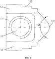
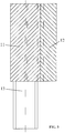
- the rotor pins 8 and the stator pins 7 are the same in structure, comprising quadrangular steel billet 11 whose cross section is square and a screwed or non-screwed connecting rod 13 on the steel billet 11.
- An anti-abrasion component 12 is fixed on the quadrangular steel billet 11 of the rotor pin 6 or the stator pin 5. Fixed joint between the steel billet 11 and the anti-abrasion component 12 is soldering joint or bonding joint.
- the anti-abrasion component 12 is made of cemented carbide or ceramic materials.
- the anti-abrasion component 12 comprises two level parts and a V-shaped part.
- the two-level parts are fixed on the end of the two inclined faces of V-shaped part respectively, both the two-level parts and two inclined faces of the V-shaped part are disposed symmetrically about a center of the quadrangular steel billet 11.
- the level part comprises two to six steps.
- the V-shaped part comprises an arc-shaped apical part and the included angle of the two inclined faces is between 80 and 140 degrees.
- the radial working face 121 results from two inclined faces and arc face of the V-shaped part, while the tangential working face 122 results from the two to six steps of the two-level parts.
- the direction nearer to the radial working face 121 is regarded as front direction, while the direction farther from from radial working face 121 is regarded as rear direction.
- the height of the steps increased from 0.5 mm to 1.5 mm along the direction from front to rear successively.
- the width of the bottommost steps of the inner or outer tangential working faces 122 of the anti-abrasion component 12 is no less than 1 mm.
- the width of the uppermost steps of the inner or outer tangential working faces 122 of the anti-abrasion component 12 is between 3 mm and 15 mm.
- the anti-abrasion component 12 is made of cemented carbide or ceramic materials.
- the arc faces of the radial working faces 121 of the rotor pins 6 and the arc faces of the radial working faces 121 of the stator pins 5 are opposite to one another.
- the inner and outer tangential working faces 122 of the rotor pins 6 and the inner and outer tangential working faces 122 of the stator pins 5 are all tangential to the peripheral direction of the motor movement.
- the minimum space between the highest step of the tangential working face 122 outward of the rotor pin 6 and the highest step of the tangential working face 122 inward of the nearest the stator pin 5, or the minimum space between the highest step of the tangential working face 122 inward of the rotor pin 6 and the highest step of the tangential working face 122 outward of the nearest the stator pin 5, can be regarded as minimum space L min between the rotor pin 6 and the stator pin 5.
- the minimum space L min between the rotor pin 6 and the stator pin 5 is between 0.5 mm and 3 mm.
- the maximum space between the start point of outward apical inclined face of the radial working face 121 of the rotor pin 6 and the start point of inward apical inclined face of the radial working face 121 of the stator pin 5, can be regarded as the maximum space L max between the rotor pin 6 and the stator pin 5.
- the maximum space L max between the rotor pin 6 and the stator pin 5 is between 10 mm and 20 mm.
- the radial space between the rotor pins 6 and the stator pins 5 is always changing from maximum space L max to minimum space L min .
- L min can be designed in the range from 0.5 mm to 3 mm (almost all grinders of same sorts require the particle size of unpulverized material to be larger than 0.5 mm)
- L max setting from 10 mm to 20 mm
- the unusually large extrusion cutting force will rapidly pulverize big particles clamped between radial working face 121 of the rotor pin 6 and radial forking face 121 of the stator pin 5 into small particles, then these small particles will be pulverized again when entering tangential working face 122.
- Radial working face 121 of the pins (in particular, the arc face at the apical intersection of two inclined faces) can divide the incoming materials into both two sides evenly, aggregating materials onto the tangential working face 122 for pulverization, which is crucial for improved pulverizing and efficiency.
- the energy cost just comprises idle load consumption, pulverizing consumption, heat generated by material pulverization and rotor driven material movement consumption totally four consumptions. Since the structure of the present invention is simple, the idle load consumption is lower than most of other pulverizers.
- stator pins 6 drive materials to move circularly meanwhile from the center to periphery of the rotor, then expelled from outlet hole 1 on the machine shell 4.
- the chance of driving material particles to move is just once (while several times in prior ball mills and cone crushers), the energy consumption of rotor driven material movement is much lower than most of other pulverizers.
- the pulverizing related structure features and working principles are the same as the example 1, so example 2 adopts all the advantages of the above-mentioned example 1, where the only difference is a water-cooling unit is added in example 2.
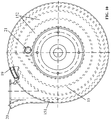
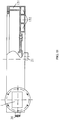
- the water channel 14 is disposed inside the cover plate 3
- second annular water channel 15 is disposed inside the machine shell 4.
- the bottom surface of aluminum made heat-conducting plate 16 is fixed tightly with the stator pins 5 and the nut used to install the stator pin 5.
- the top surface of heat-conducting plate 16 is fixed tightly with the bottom surface of the cover plate 3.
- the second annular water channel 15 is disposed inside the machine shell 4.
- the second annular water channel 15 can be further divided into a volute water channel 151 and a bottom case water channel 152.
- the volute water channel 151 is disposed in the outer part of the machine shell 4, while the bottom case water channel 152 is disposed as several continuous rounds of water channel around the flange plate of motor 10 added in the bottom of the machine shell 4.
- Rectangular water hole 19 connects the volute water channel 151 with the bottom case water channel 152 at the bottom of the machine shell 4.
- Water inlet tube 20 of the second annular water channel is located near the outlet hole 1 on the machine shell 4.
- Water outlet tube 21 of the second annular water channel is located near the motor 10 at the bottom of the machine shell 4.
- cooling water removes heat generated by material pulverization and motor rotation, achieving the goal of lowering the temperature of pulverized materials.
- the grinder has the advantage of cooling down the temperature of pulverized materials.
- the high-speed extrusion cutting grinder provided in the present invention can be widely used in various fields such as grain processing, fodder processing, metallurgy, chemical engineering, plastics, pharmaceuticals, architectures, electronics and energy industries. It can effectively pulverize almost all solid particle materials such as grains, oil plants, sorts of plant roots, stems, leaves and seeds, ores, rubbers and plastics, with advantages such as simple manufacturing process and easy installation and operation, low energy consumption and high utilization of effective electric power.
Landscapes
- Engineering & Computer Science (AREA)
- Food Science & Technology (AREA)
- Crushing And Pulverization Processes (AREA)
- Crushing And Grinding (AREA)
Applications Claiming Priority (2)
| Application Number | Priority Date | Filing Date | Title |
|---|---|---|---|
| CN201510793292.3A CN105268528B (zh) | 2015-11-18 | 2015-11-18 | 高速挤切粉碎机 |
| PCT/CN2016/100235 WO2017084434A1 (fr) | 2015-11-18 | 2016-09-27 | Broyeur par extrusion à grande vitesse |
Publications (2)
| Publication Number | Publication Date |
|---|---|
| EP3378565A1 true EP3378565A1 (fr) | 2018-09-26 |
| EP3378565A4 EP3378565A4 (fr) | 2019-07-31 |
Family
ID=55138881
Family Applications (1)
| Application Number | Title | Priority Date | Filing Date |
|---|---|---|---|
| EP16865612.2A Withdrawn EP3378565A4 (fr) | 2015-11-18 | 2016-09-27 | Broyeur par extrusion à grande vitesse |
Country Status (5)
| Country | Link |
|---|---|
| US (1) | US20180257083A1 (fr) |
| EP (1) | EP3378565A4 (fr) |
| JP (1) | JP2018534134A (fr) |
| CN (1) | CN105268528B (fr) |
| WO (1) | WO2017084434A1 (fr) |
Families Citing this family (7)
| Publication number | Priority date | Publication date | Assignee | Title |
|---|---|---|---|---|
| CN105268528B (zh) * | 2015-11-18 | 2017-12-05 | 王洪福 | 高速挤切粉碎机 |
| WO2017093513A1 (fr) * | 2015-12-04 | 2017-06-08 | Bühler AG | Rotor, meuleuse, enveloppe d'aspiration d'air et élément abasif pour meuleuse |
| CN107442210B (zh) * | 2017-10-13 | 2019-03-26 | 王洪福 | 高效低温挤切粉碎小麦制粉工艺及制粉装置 |
| CN109317273A (zh) * | 2018-11-01 | 2019-02-12 | 王双彬 | 一种粘土剪切粉碎机 |
| CN111298903B (zh) * | 2020-03-05 | 2021-11-09 | 郑州鸿力农业科技有限公司 | 一种多功能挤切机及其应用 |
| CN111482253A (zh) * | 2020-04-17 | 2020-08-04 | 廊坊市恒诺机械有限公司 | 破壁微碎机 |
| US20250041872A1 (en) * | 2021-08-31 | 2025-02-06 | Moviator Oy | Apparatus and method for crushing lumpy material |
Family Cites Families (32)
| Publication number | Priority date | Publication date | Assignee | Title |
|---|---|---|---|---|
| GB943319A (en) * | 1962-03-12 | 1963-12-04 | J M J Ind Inc | Disintegrating mill |
| CA1180926A (fr) * | 1981-09-30 | 1985-01-15 | David R. Webster | Installation et methode d'affinage des pates a papier |
| DE3429365C2 (de) * | 1984-04-18 | 1986-04-17 | Eggeling, Ernst, 4600 Dortmund | Desintegrator für die Prallzerkleinerung von Mahlgut, insbesondere von mineralischem Mahlgut |
| US4767065A (en) * | 1987-01-12 | 1988-08-30 | Jjw, Inc. | Material pulverizing apparatus |
| CN1071141C (zh) * | 1990-01-31 | 2001-09-19 | 布勒公司 | 冲击式撞碎机 |
| JP2554833Y2 (ja) * | 1991-12-17 | 1997-11-19 | ニチアス株式会社 | 高速回転微粉砕機 |
| US5971307A (en) * | 1998-02-13 | 1999-10-26 | Davenport; Ricky W. | Rotary grinder |
| DE4322757C1 (de) * | 1993-07-08 | 1994-07-21 | Holger Hannemann | Desintegrator |
| JPH07227550A (ja) * | 1994-02-17 | 1995-08-29 | Satake Eng Co Ltd | 研削式竪型精穀機 |
| JPH105607A (ja) * | 1996-06-27 | 1998-01-13 | Toyota Motor Corp | 破砕機 |
| US5971305A (en) * | 1997-07-21 | 1999-10-26 | Davenport; Ricky W. | Rotary shredder |
| US7530513B2 (en) * | 2001-10-18 | 2009-05-12 | Aerosion, Ltd. | Apparatus and methodology for comminuting materials |
| DE102005020441A1 (de) * | 2005-04-29 | 2006-11-02 | Silver Cay Worldwide Corp. | Vorrichtung und Verfahren zum Behandeln von Verbundelementen |
| US7472855B2 (en) * | 2006-01-09 | 2009-01-06 | Andritz Inc. | Refiner stator plate having an outer row of teeth slanted to deflect pulp and method for pulp deflection during refining |
| US7478773B2 (en) * | 2006-01-09 | 2009-01-20 | Andritz Inc. | Tooth refiner plates having V-shaped teeth and refining method |
| FI118525B (fi) * | 2006-05-31 | 2007-12-14 | Metso Powdermet Oy | Menetelmä monimateriaalikomponentin tai -rakenteen valmistamiseksi |
| US7753303B2 (en) * | 2006-09-21 | 2010-07-13 | Hall David R | Rotary shaft impactor |
| CN101021228A (zh) * | 2006-10-17 | 2007-08-22 | 王洪福 | 钢坯硬质合金柱销 |
| CN101411999B (zh) * | 2008-10-31 | 2011-05-11 | 江南大学 | 高油脂物料微细化粉碎装置 |
| CN102049326A (zh) * | 2009-10-29 | 2011-05-11 | 王洪福 | 撞击脱皮脱胚机 |
| DE102009052356A1 (de) * | 2009-11-07 | 2011-06-01 | Ceramtec-Etec Gmbh | Auskleidung für eine Trommel einer Kugelmühle |
| DE102009054215B4 (de) * | 2009-11-21 | 2015-12-03 | Ika-Werke Gmbh & Co. Kg | Vorrichtung zum Zerkleinern oder Mahlen |
| CN102658055B (zh) * | 2012-06-07 | 2015-09-09 | 王洪福 | 多棱柱搅拌棒 |
| CN202638319U (zh) * | 2012-06-07 | 2013-01-02 | 王洪福 | 卧式多功能搅拌机 |
| CN102744122B (zh) * | 2012-07-13 | 2014-06-04 | 王洪福 | 带有水冷功能的撞击磨粉杀虫机 |
| US20140131487A1 (en) * | 2012-11-09 | 2014-05-15 | E I Du Pont De Nemours And Company | System including a combined tangential shear homogenizing and flashing apparatus having single or dual effluent outlet(s) and method for flash treating biomass utilizing the same |
| CN102921519B (zh) * | 2012-11-23 | 2014-09-03 | 王洪福 | 具有撞击粉碎和挤压剪切粉碎功能的粉碎机 |
| CN102943799B (zh) * | 2012-11-23 | 2014-10-29 | 王洪福 | 多棱柱销及转子柱销与定子柱销的配合结构 |
| CN103223365B (zh) * | 2013-04-28 | 2014-12-10 | 王洪福 | 具有撞击粉碎和挤压剪切粉碎功能的粉碎机 |
| CN103831155B (zh) * | 2013-12-11 | 2016-04-20 | 河北苹乐面粉机械集团有限公司 | 参数可调的实验用撞击磨粉机 |
| EP2940169A1 (fr) * | 2014-04-30 | 2015-11-04 | Sandvik Intellectual Property AB | Composant résistant à l'usure et dispositif de décomposition mécanique de matériau pourvu d'un tel composant |
| CN105268528B (zh) * | 2015-11-18 | 2017-12-05 | 王洪福 | 高速挤切粉碎机 |
-
2015
- 2015-11-18 CN CN201510793292.3A patent/CN105268528B/zh not_active Expired - Fee Related
-
2016
- 2016-09-27 WO PCT/CN2016/100235 patent/WO2017084434A1/fr not_active Ceased
- 2016-09-27 JP JP2018521872A patent/JP2018534134A/ja active Pending
- 2016-09-27 EP EP16865612.2A patent/EP3378565A4/fr not_active Withdrawn
-
2018
- 2018-05-13 US US15/978,183 patent/US20180257083A1/en not_active Abandoned
Also Published As
| Publication number | Publication date |
|---|---|
| EP3378565A4 (fr) | 2019-07-31 |
| CN105268528B (zh) | 2017-12-05 |
| US20180257083A1 (en) | 2018-09-13 |
| JP2018534134A (ja) | 2018-11-22 |
| CN105268528A (zh) | 2016-01-27 |
| WO2017084434A1 (fr) | 2017-05-26 |
Similar Documents
| Publication | Publication Date | Title |
|---|---|---|
| EP3378565A1 (fr) | Broyeur par extrusion à grande vitesse | |
| US8302892B2 (en) | Conical-shaped impact mill | |
| CN201728133U (zh) | 多级粉碎机 | |
| AU2008236851B2 (en) | Conical-shaped impact mill | |
| CA2774862C (fr) | Super pulverisateur | |
| CN108435370A (zh) | 一种超微中草药粉碎机 | |
| CN102210989A (zh) | 乳化机及其乳化方法 | |
| CN103272674B (zh) | 一种用于从棉粕中提取棉蛋白的气流涡旋微粉机 | |
| CN111298903B (zh) | 一种多功能挤切机及其应用 | |
| CN212284156U (zh) | 一种植物粉碎装置 | |
| CN208302949U (zh) | 一种超微中草药粉碎机 | |
| JP4947707B2 (ja) | 粉砕装置 | |
| US20120132736A1 (en) | Silicon metal grinding machine | |
| US11759788B2 (en) | Grinding apparatus | |
| CN223970023U (zh) | 立式超微粉碎机 | |
| CN104888893B (zh) | 一种鱼粉粉碎装置 | |
| KR101065755B1 (ko) | 분쇄기 | |
| CN223970022U (zh) | 立式超微粉碎机 | |
| WO2016041336A1 (fr) | Meuleuse à tourbillon cyclonique multi-étage | |
| RU2840465C1 (ru) | Центробежный дисковый измельчитель | |
| CN210386035U (zh) | 一种中草药超微粉碎机 | |
| JP3110342U (ja) | 粉砕装置 | |
| CN204017963U (zh) | 一种粉碎磨粉机 | |
| CN201586539U (zh) | 一种五谷精磨机的组合式动磨盘 | |
| CN104815722A (zh) | 锤片粉碎机 |
Legal Events
| Date | Code | Title | Description |
|---|---|---|---|
| STAA | Information on the status of an ep patent application or granted ep patent |
Free format text: STATUS: THE INTERNATIONAL PUBLICATION HAS BEEN MADE |
|
| PUAI | Public reference made under article 153(3) epc to a published international application that has entered the european phase |
Free format text: ORIGINAL CODE: 0009012 |
|
| STAA | Information on the status of an ep patent application or granted ep patent |
Free format text: STATUS: REQUEST FOR EXAMINATION WAS MADE |
|
| 17P | Request for examination filed |
Effective date: 20180516 |
|
| AK | Designated contracting states |
Kind code of ref document: A1 Designated state(s): AL AT BE BG CH CY CZ DE DK EE ES FI FR GB GR HR HU IE IS IT LI LT LU LV MC MK MT NL NO PL PT RO RS SE SI SK SM TR |
|
| AX | Request for extension of the european patent |
Extension state: BA ME |
|
| DAV | Request for validation of the european patent (deleted) | ||
| DAX | Request for extension of the european patent (deleted) | ||
| A4 | Supplementary search report drawn up and despatched |
Effective date: 20190627 |
|
| RIC1 | Information provided on ipc code assigned before grant |
Ipc: B02C 19/00 20060101ALI20190621BHEP Ipc: B02C 13/24 20060101ALI20190621BHEP Ipc: B02C 13/20 20060101ALI20190621BHEP Ipc: B02C 23/00 20060101AFI20190621BHEP Ipc: B02C 13/28 20060101ALI20190621BHEP |
|
| STAA | Information on the status of an ep patent application or granted ep patent |
Free format text: STATUS: THE APPLICATION IS DEEMED TO BE WITHDRAWN |
|
| 18D | Application deemed to be withdrawn |
Effective date: 20200128 |