EP3378600A1 - Rückkehrvorrichtung - Google Patents
Rückkehrvorrichtung Download PDFInfo
- Publication number
- EP3378600A1 EP3378600A1 EP18152076.8A EP18152076A EP3378600A1 EP 3378600 A1 EP3378600 A1 EP 3378600A1 EP 18152076 A EP18152076 A EP 18152076A EP 3378600 A1 EP3378600 A1 EP 3378600A1
- Authority
- EP
- European Patent Office
- Prior art keywords
- return
- wheel
- flywheel
- gun body
- driven
- Prior art date
- Legal status (The legal status is an assumption and is not a legal conclusion. Google has not performed a legal analysis and makes no representation as to the accuracy of the status listed.)
- Granted
Links
Images


Classifications
-
- B—PERFORMING OPERATIONS; TRANSPORTING
- B25—HAND TOOLS; PORTABLE POWER-DRIVEN TOOLS; MANIPULATORS
- B25C—HAND-HELD NAILING OR STAPLING TOOLS; MANUALLY OPERATED PORTABLE STAPLING TOOLS
- B25C1/00—Hand-held nailing tools; Nail feeding devices
- B25C1/06—Hand-held nailing tools; Nail feeding devices operated by electric power
-
- B—PERFORMING OPERATIONS; TRANSPORTING
- B25—HAND TOOLS; PORTABLE POWER-DRIVEN TOOLS; MANIPULATORS
- B25C—HAND-HELD NAILING OR STAPLING TOOLS; MANUALLY OPERATED PORTABLE STAPLING TOOLS
- B25C1/00—Hand-held nailing tools; Nail feeding devices
- B25C1/001—Nail feeding devices
-
- B—PERFORMING OPERATIONS; TRANSPORTING
- B25—HAND TOOLS; PORTABLE POWER-DRIVEN TOOLS; MANIPULATORS
- B25C—HAND-HELD NAILING OR STAPLING TOOLS; MANUALLY OPERATED PORTABLE STAPLING TOOLS
- B25C1/00—Hand-held nailing tools; Nail feeding devices
- B25C1/04—Hand-held nailing tools; Nail feeding devices operated by fluid pressure, e.g. by air pressure
-
- B—PERFORMING OPERATIONS; TRANSPORTING
- B25—HAND TOOLS; PORTABLE POWER-DRIVEN TOOLS; MANIPULATORS
- B25C—HAND-HELD NAILING OR STAPLING TOOLS; MANUALLY OPERATED PORTABLE STAPLING TOOLS
- B25C1/00—Hand-held nailing tools; Nail feeding devices
- B25C1/008—Safety devices
-
- B—PERFORMING OPERATIONS; TRANSPORTING
- B25—HAND TOOLS; PORTABLE POWER-DRIVEN TOOLS; MANIPULATORS
- B25C—HAND-HELD NAILING OR STAPLING TOOLS; MANUALLY OPERATED PORTABLE STAPLING TOOLS
- B25C5/00—Manually operated portable stapling tools; Hand-held power-operated stapling tools; Staple feeding devices therefor
- B25C5/10—Driving means
- B25C5/15—Driving means operated by electric power
Definitions
- the disclosure relates to a return device, and more particularly to a return device adapted for use in a fastening tool, and disposed for returning an impact member from a strike position to a standby position after a nail striking operation is completed.
- Each of conventional electric nail guns disclosed in Taiwanese patent Nos. M513761 , 1445601 and M482482 has a resilient member disposed for returning an impact member to a standby position after a nail striking operation is completed.
- the resilient member may be an elastic rubber or a spring.
- the resilient member since the resilient member is stretched during the nail striking operation, and provides a resilient force to return the impact member to the standby position, the resilient member may suffer from elastic fatigue problem after having been stretched for many times. As a result, the service life of the resilient member is short and the resilient force of the resilient member is gradually decreased.
- the object of the disclosure is to provide a return device that can greatly improve the smoothness and the output kinetic energy of a nail striking operation.
- the return device is adapted for use in a fastening tool.
- the fastening tool includes a gun body, an electrically rotatable flywheel mounted rotatably to the gun body, and an impact member contactable with the flywheel, and movable between a standby position, where the impact member is close to a rear end portion of the gun body, and a strike position, where the impact member is close to a front end portion of the gun body.
- the return device includes a return wheel unit, and a driving unit.
- the return wheel unit is adapted to be mounted to the gun body, and includes a return wheel movable between a free position, where the return wheel is not in contact with the impact member, and a return position, where the impact member is at the strike position and is not contact with the flywheel, and where the return wheel is in contact with the flywheel and the impact member such that, when the flywheel rotates in a first rotational direction, the return wheel is driven by the flywheel to rotate in a second rotational direction which is opposite to the first rotational direction, and moves the impact member from the strike position to the standby position.
- the driving unit is adapted to be mounted to the gun body, and drives the movement of the return wheel between the free position and the return position.
- the fastening tool 1 includes a gun body 10, a central shaft 11 mounted to the gun body 10, an electrically rotatable flywheel 12 rotatably mounted to the gun body 10, an arm 13 pivotally mounted to the gun body 10, and an impact member 14 contactable with the flywheel 12 as a result of movement of the arm 13 toward the flywheel 12.
- the gun body 10 has a first channel 101 opening toward the flywheel 12 and the impact member 14, a front end portion 102, and a rear end portion 103 which is opposite to the front end portion 102.
- the impact member 14 is movable in a longitudinal direction (X) of the arm 13 by virtue of a throwing force of the flywheel 12 between a standby position, where the impact member 14 is close to the rear end portion 103 of the gun body 10, and a strike position, where the impact member 14 is close to the front end portion 102 of the gun body 10.
- the return device includes a return wheel unit 2 and a driving unit 3.
- the return wheel unit 2 is adapted to be mounted to the gun body 10 at a location close to the flywheel 12, and includes a wheel support 21 adapted to be received in the first channel 101 of the gun body 10, a return wheel 22 rotatably mounted to the wheel support 21, and movable between a free position (see Figures 4 and 5 ) and a return position (see Figures 6 and 7 ), and at least one resilient member 23 adapted to be connected between the wheel support 21 and the gun body 10 (see Figure 3A ). When the return wheel 22 is at the free position, the return wheel 22 is not in contact with the impact member 14.
- the return wheel unit 2 includes two resilient members 23, and the number of the resilient members 23 may be varied in other embodiments.
- the resilient members 23 are respectively disposed at two opposite sides of the wheel support 21, and are disposed for providing resilient forces to bias the return wheel 22 to move to the free position.
- the driving unit 3 is adapted to be mounted to the gun body 10, and drives the movement of the return wheel 22 between the free position and the return position.
- the driving unit 3 includes a driving member 31 having a main body 311, and a rod member 312 that is movable relative to the main body 311.
- One of the main body 311 and the rod member 312 is adapted to be fixedly connected to the gun body 10.
- the main body 311 is adapted to be fixedly connected to the gun body 10
- the rod member 312 is electrically driven to push the wheel support 21 so as to move the return wheel 22 to the return position.
- the arm 13 pivots away from the flywheel 12, such that the impact member 14 is not in contact with the flywheel 12.
- the rod member 312 of the driving member 31 is electrically driven to drive the wheel support 21 to overcome the resilient forces of the resilient members 23 so as to move toward the flywheel 12 along the first channel 101.
- the return wheel 22 is in contact with the flywheel 12 and the impact member 14.
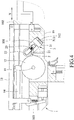
- the second embodiment has a structure similar to that of the first embodiment.
- the gun body 10 of the fastening tool 1 further has a second channel 104 extending in a driving direction which is perpendicular to the longitudinal direction (X), and communicated with the first channel 101, and a third channel 105 extending parallel to the second channel 104.
- the main difference between this embodiment and the previous embodiment resides in the configuration of the driving unit 3.
- the driving unit 3 further includes a guiding member 32 adapted to be received in the gun body 10, and a driven member 33.
- the driving member 31 is adapted to be received in the third channel 105 such that, the rod member 312 is movable relative to the driven member 33 in the driving direction.
- the guiding member 32 is adapted to be received in the second channel 104, is movable in the driving direction, is mounted between the driven member 33 and the wheel support 21, and has an inclined surface 321 abutting against the wheel support 21, and disposed for pushing the wheel support 21.
- the driven member 33 is driven by the driving member 31, and has a middle portion adapted to be pivotally connected to the gun body 10, and two end portions 331 respectively abutting against the rod member 312 of the driving member 31 and the guiding member 32.
- the driven member 33 pivots to push the guiding member 32 with the other one of the end portions 331.
- the guiding member 32 subsequently moves in the second channel 104 toward the wheel support 21 to drive the wheel support 21 with the inclined surface 321 to move in the first channel 101 against the resilient forces of the resilient members 23.
- the return wheel 22 is carried by the wheel support 21 to move to the return position, and comes into contact with the flywheel 12 and the impact member 14 so as to drive the impact member 14 to move back to the standby position.
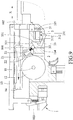
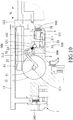
- the third embodiment has a structure similar to that of the second embodiment.
- the main difference between this embodiment and the previous embodiment resides in the configuration of the return wheel unit 2.
- the wheel support 21 has two pivot portions 211 adapted to be pivotally and respectively connected to two opposite ends of the central shaft 11, and a frame portion 212 connected to the pivot portions 211, movable in the first channel 101, disposed for allowing the return wheel 22 to be rotatably mounted thereto, and driven by the driving unit 3.
- the flywheel 12 is in rollable contact with the return wheel 22 and rotates in the first rotational direction, and the return wheel 22 is driven by the flywheel 12 to rotate in the second rotational direction.
- the rod member 312 of the driving member 31 is electrically driven to move in the driving direction and pushes a corresponding one of the end portions 331 of the driven member 33
- the driven member 33 pivots to push the guiding member 32 with the other one of the end portions 331.
- the guiding member 32 subsequently moves in the second channel 104 toward the frame portion 212 of the wheel support 21 to drive the frame portion 212 of the wheel support 21 with the inclined surface 321 to move in the first channel 101 against the resilient forces of the resilient members 23.
- the return wheel 22 is carried by the wheel support 21 to move to the return position so as to drive the impact member 14 to move back to the standby position.
- the pivot portions 211 swing slightly when the return wheel 22 moves from the free position to the return position to allow smooth movement of the frame portion 212 in the first channel 101, the return wheel 22 can move along an outer periphery of the flywheel 12. As such, the slight angular movement of the pivot portions 212 is compensated for by the deformations of the resilient members 23, and the moving smoothness of the frame portion 212 of the wheel support 21 in the first channel 101 is not affected.
- the return device of the disclosure has the following advantages:
Landscapes
- Engineering & Computer Science (AREA)
- Mechanical Engineering (AREA)
- Physics & Mathematics (AREA)
- Fluid Mechanics (AREA)
- Portable Nailing Machines And Staplers (AREA)
Applications Claiming Priority (1)
| Application Number | Priority Date | Filing Date | Title |
|---|---|---|---|
| TW106101657A TWI714707B (zh) | 2017-01-18 | 2017-01-18 | 電動釘槍的無阻式回收裝置 |
Publications (2)
| Publication Number | Publication Date |
|---|---|
| EP3378600A1 true EP3378600A1 (de) | 2018-09-26 |
| EP3378600B1 EP3378600B1 (de) | 2019-12-25 |
Family
ID=61002897
Family Applications (1)
| Application Number | Title | Priority Date | Filing Date |
|---|---|---|---|
| EP18152076.8A Active EP3378600B1 (de) | 2017-01-18 | 2018-01-17 | Rückkehrvorrichtung |
Country Status (4)
| Country | Link |
|---|---|
| US (1) | US10549413B2 (de) |
| EP (1) | EP3378600B1 (de) |
| JP (1) | JP6584540B2 (de) |
| TW (1) | TWI714707B (de) |
Families Citing this family (3)
| Publication number | Priority date | Publication date | Assignee | Title |
|---|---|---|---|---|
| TWI772797B (zh) * | 2020-05-18 | 2022-08-01 | 鑽全實業股份有限公司 | 可釋放導軌的衝擊裝置 |
| TWI809915B (zh) * | 2022-06-13 | 2023-07-21 | 力肯實業股份有限公司 | 電動釘槍之飛輪式驅動擊釘裝置 |
| DE102024203165A1 (de) | 2024-04-08 | 2025-10-09 | Robert Bosch Gesellschaft mit beschränkter Haftung | Eintreibgerät mit einem Schwungradmechanismus |
Citations (6)
| Publication number | Priority date | Publication date | Assignee | Title |
|---|---|---|---|---|
| US4964558A (en) * | 1989-05-26 | 1990-10-23 | Sencorp | Electro-mechanical fastener driving tool |
| US20060261126A1 (en) * | 2005-05-18 | 2006-11-23 | Hilti Aktiengesellschaft | Electrically operated drive-in tool |
| TWM482482U (zh) | 2014-03-10 | 2014-07-21 | Basso Ind Corp | 電動釘槍回收裝置 |
| TWI445601B (de) | 2013-04-11 | 2014-07-21 | ||
| US20150352702A1 (en) * | 2014-06-05 | 2015-12-10 | Basso Industry Corp. | Handheld power tool and impact block return device thereof |
| TWM513761U (zh) | 2015-07-16 | 2015-12-11 | yong-tang Zhang | 水龍頭拆裝工具改良 |
Family Cites Families (14)
| Publication number | Priority date | Publication date | Assignee | Title |
|---|---|---|---|---|
| US4215808A (en) * | 1978-12-22 | 1980-08-05 | Sollberger Roger W | Portable electric fastener driving apparatus |
| US6607111B2 (en) * | 2000-12-22 | 2003-08-19 | Senco Products, Inc. | Flywheel operated tool |
| CA2479979C (en) * | 2002-07-25 | 2007-03-13 | Yih Kai Enterprise Co., Ltd. | Handy electric nailing gun |
| JP4321393B2 (ja) * | 2004-07-20 | 2009-08-26 | マックス株式会社 | ファスナ打込機 |
| US6971567B1 (en) * | 2004-10-29 | 2005-12-06 | Black & Decker Inc. | Electronic control of a cordless fastening tool |
| US20060180631A1 (en) * | 2005-02-16 | 2006-08-17 | Chris Pedicini | Electric motor driven energy storage device for impacting |
| JP2007237351A (ja) * | 2006-03-09 | 2007-09-20 | Hitachi Koki Co Ltd | 携帯用打込機 |
| US8763874B2 (en) * | 2007-10-05 | 2014-07-01 | Senco Brands, Inc. | Gas spring fastener driving tool with improved lifter and latch mechanisms |
| EP2209593B1 (de) * | 2007-10-05 | 2016-07-20 | Senco Brands, Inc | Eine gasfeder verwendendes werkzeug zum eintreiben von befestigungselementen |
| EP2527095B1 (de) * | 2008-05-30 | 2013-12-25 | Black & Decker Inc. | Werkzeug zum Eintreiben von Befestigungselementen |
| TWI385058B (zh) * | 2010-04-26 | 2013-02-11 | Basso Ind Corp | Electric nail gun drive device |
| US9539714B1 (en) * | 2014-10-07 | 2017-01-10 | Tricord Solutions, Inc. | Fastener driving apparatus |
| CN208289826U (zh) * | 2015-02-06 | 2018-12-28 | 米沃奇电动工具公司 | 以气弹簧为动力的紧固件驱动器 |
| TWM513764U (zh) * | 2015-06-11 | 2015-12-11 | Basso Ind Corp | 電動釘槍的回收裝置 |
-
2017
- 2017-01-18 TW TW106101657A patent/TWI714707B/zh active
-
2018
- 2018-01-16 US US15/872,159 patent/US10549413B2/en active Active
- 2018-01-17 EP EP18152076.8A patent/EP3378600B1/de active Active
- 2018-01-17 JP JP2018005505A patent/JP6584540B2/ja not_active Expired - Fee Related
Patent Citations (6)
| Publication number | Priority date | Publication date | Assignee | Title |
|---|---|---|---|---|
| US4964558A (en) * | 1989-05-26 | 1990-10-23 | Sencorp | Electro-mechanical fastener driving tool |
| US20060261126A1 (en) * | 2005-05-18 | 2006-11-23 | Hilti Aktiengesellschaft | Electrically operated drive-in tool |
| TWI445601B (de) | 2013-04-11 | 2014-07-21 | ||
| TWM482482U (zh) | 2014-03-10 | 2014-07-21 | Basso Ind Corp | 電動釘槍回收裝置 |
| US20150352702A1 (en) * | 2014-06-05 | 2015-12-10 | Basso Industry Corp. | Handheld power tool and impact block return device thereof |
| TWM513761U (zh) | 2015-07-16 | 2015-12-11 | yong-tang Zhang | 水龍頭拆裝工具改良 |
Also Published As
| Publication number | Publication date |
|---|---|
| TWI714707B (zh) | 2021-01-01 |
| EP3378600B1 (de) | 2019-12-25 |
| JP6584540B2 (ja) | 2019-10-02 |
| US20190022843A1 (en) | 2019-01-24 |
| JP2018118374A (ja) | 2018-08-02 |
| US10549413B2 (en) | 2020-02-04 |
| TW201827176A (zh) | 2018-08-01 |
Similar Documents
| Publication | Publication Date | Title |
|---|---|---|
| US7513407B1 (en) | Counterforce-counteracting device for a nailer | |
| US10195729B2 (en) | Driving device | |
| US8479966B2 (en) | Floating impact apparatus for electrical nail gun | |
| EP2644323B1 (de) | Elektrische Nagelpistole | |
| AU751720B2 (en) | Multi-stroke fastening device | |
| EP3378600B1 (de) | Rückkehrvorrichtung | |
| US20150251300A1 (en) | Electric nail gun | |
| US11518013B2 (en) | Electric nail gun | |
| US20150306753A1 (en) | Adjusting device for an electric nail gun | |
| US20210354278A1 (en) | Impact device | |
| EP4091770A1 (de) | Nagelpistole | |
| EP2433752A2 (de) | Antriebseinheit für eine elektrische Nagelpistole | |
| US11819991B2 (en) | Retaining device for use with a nail gun | |
| US9803948B2 (en) | Trigger emulation mechanism of electric gun | |
| GB2391178A (en) | Ball trapping and shooting device | |
| US11738431B2 (en) | Retaining device for use with a nail gun | |
| US12202111B2 (en) | Electric nail gun | |
| EP4029653B1 (de) | Haltevorrichtung zur verwendung mit einer nagelpistole | |
| CN219764487U (zh) | 玩具发射器 | |
| GB2452935A (en) | Counterforce device for a nailer | |
| EP3040674B1 (de) | Auslöseremulationsmechanismus für elektrische Pistole | |
| JPS6150577A (ja) | 打撃練習機 |
Legal Events
| Date | Code | Title | Description |
|---|---|---|---|
| PUAI | Public reference made under article 153(3) epc to a published international application that has entered the european phase |
Free format text: ORIGINAL CODE: 0009012 |
|
| STAA | Information on the status of an ep patent application or granted ep patent |
Free format text: STATUS: REQUEST FOR EXAMINATION WAS MADE |
|
| 17P | Request for examination filed |
Effective date: 20180117 |
|
| AK | Designated contracting states |
Kind code of ref document: A1 Designated state(s): AL AT BE BG CH CY CZ DE DK EE ES FI FR GB GR HR HU IE IS IT LI LT LU LV MC MK MT NL NO PL PT RO RS SE SI SK SM TR |
|
| AX | Request for extension of the european patent |
Extension state: BA ME |
|
| GRAP | Despatch of communication of intention to grant a patent |
Free format text: ORIGINAL CODE: EPIDOSNIGR1 |
|
| STAA | Information on the status of an ep patent application or granted ep patent |
Free format text: STATUS: GRANT OF PATENT IS INTENDED |
|
| INTG | Intention to grant announced |
Effective date: 20190611 |
|
| GRAJ | Information related to disapproval of communication of intention to grant by the applicant or resumption of examination proceedings by the epo deleted |
Free format text: ORIGINAL CODE: EPIDOSDIGR1 |
|
| GRAL | Information related to payment of fee for publishing/printing deleted |
Free format text: ORIGINAL CODE: EPIDOSDIGR3 |
|
| STAA | Information on the status of an ep patent application or granted ep patent |
Free format text: STATUS: REQUEST FOR EXAMINATION WAS MADE |
|
| GRAS | Grant fee paid |
Free format text: ORIGINAL CODE: EPIDOSNIGR3 |
|
| GRAR | Information related to intention to grant a patent recorded |
Free format text: ORIGINAL CODE: EPIDOSNIGR71 |
|
| STAA | Information on the status of an ep patent application or granted ep patent |
Free format text: STATUS: GRANT OF PATENT IS INTENDED |
|
| INTC | Intention to grant announced (deleted) | ||
| GRAA | (expected) grant |
Free format text: ORIGINAL CODE: 0009210 |
|
| STAA | Information on the status of an ep patent application or granted ep patent |
Free format text: STATUS: THE PATENT HAS BEEN GRANTED |
|
| AK | Designated contracting states |
Kind code of ref document: B1 Designated state(s): AL AT BE BG CH CY CZ DE DK EE ES FI FR GB GR HR HU IE IS IT LI LT LU LV MC MK MT NL NO PL PT RO RS SE SI SK SM TR |
|
| INTG | Intention to grant announced |
Effective date: 20191119 |
|
| REG | Reference to a national code |
Ref country code: GB Ref legal event code: FG4D |
|
| REG | Reference to a national code |
Ref country code: CH Ref legal event code: EP |
|
| REG | Reference to a national code |
Ref country code: DE Ref legal event code: R096 Ref document number: 602018001696 Country of ref document: DE |
|
| REG | Reference to a national code |
Ref country code: AT Ref legal event code: REF Ref document number: 1216647 Country of ref document: AT Kind code of ref document: T Effective date: 20200115 |
|
| REG | Reference to a national code |
Ref country code: IE Ref legal event code: FG4D |
|
| REG | Reference to a national code |
Ref country code: NL Ref legal event code: MP Effective date: 20191225 |
|
| PG25 | Lapsed in a contracting state [announced via postgrant information from national office to epo] |
Ref country code: LT Free format text: LAPSE BECAUSE OF FAILURE TO SUBMIT A TRANSLATION OF THE DESCRIPTION OR TO PAY THE FEE WITHIN THE PRESCRIBED TIME-LIMIT Effective date: 20191225 Ref country code: NO Free format text: LAPSE BECAUSE OF FAILURE TO SUBMIT A TRANSLATION OF THE DESCRIPTION OR TO PAY THE FEE WITHIN THE PRESCRIBED TIME-LIMIT Effective date: 20200325 Ref country code: GR Free format text: LAPSE BECAUSE OF FAILURE TO SUBMIT A TRANSLATION OF THE DESCRIPTION OR TO PAY THE FEE WITHIN THE PRESCRIBED TIME-LIMIT Effective date: 20200326 Ref country code: FI Free format text: LAPSE BECAUSE OF FAILURE TO SUBMIT A TRANSLATION OF THE DESCRIPTION OR TO PAY THE FEE WITHIN THE PRESCRIBED TIME-LIMIT Effective date: 20191225 Ref country code: BG Free format text: LAPSE BECAUSE OF FAILURE TO SUBMIT A TRANSLATION OF THE DESCRIPTION OR TO PAY THE FEE WITHIN THE PRESCRIBED TIME-LIMIT Effective date: 20200325 Ref country code: SE Free format text: LAPSE BECAUSE OF FAILURE TO SUBMIT A TRANSLATION OF THE DESCRIPTION OR TO PAY THE FEE WITHIN THE PRESCRIBED TIME-LIMIT Effective date: 20191225 Ref country code: LV Free format text: LAPSE BECAUSE OF FAILURE TO SUBMIT A TRANSLATION OF THE DESCRIPTION OR TO PAY THE FEE WITHIN THE PRESCRIBED TIME-LIMIT Effective date: 20191225 |
|
| REG | Reference to a national code |
Ref country code: LT Ref legal event code: MG4D |
|
| PG25 | Lapsed in a contracting state [announced via postgrant information from national office to epo] |
Ref country code: RS Free format text: LAPSE BECAUSE OF FAILURE TO SUBMIT A TRANSLATION OF THE DESCRIPTION OR TO PAY THE FEE WITHIN THE PRESCRIBED TIME-LIMIT Effective date: 20191225 Ref country code: HR Free format text: LAPSE BECAUSE OF FAILURE TO SUBMIT A TRANSLATION OF THE DESCRIPTION OR TO PAY THE FEE WITHIN THE PRESCRIBED TIME-LIMIT Effective date: 20191225 |
|
| PG25 | Lapsed in a contracting state [announced via postgrant information from national office to epo] |
Ref country code: AL Free format text: LAPSE BECAUSE OF FAILURE TO SUBMIT A TRANSLATION OF THE DESCRIPTION OR TO PAY THE FEE WITHIN THE PRESCRIBED TIME-LIMIT Effective date: 20191225 |
|
| PG25 | Lapsed in a contracting state [announced via postgrant information from national office to epo] |
Ref country code: EE Free format text: LAPSE BECAUSE OF FAILURE TO SUBMIT A TRANSLATION OF THE DESCRIPTION OR TO PAY THE FEE WITHIN THE PRESCRIBED TIME-LIMIT Effective date: 20191225 Ref country code: PT Free format text: LAPSE BECAUSE OF FAILURE TO SUBMIT A TRANSLATION OF THE DESCRIPTION OR TO PAY THE FEE WITHIN THE PRESCRIBED TIME-LIMIT Effective date: 20200520 Ref country code: CZ Free format text: LAPSE BECAUSE OF FAILURE TO SUBMIT A TRANSLATION OF THE DESCRIPTION OR TO PAY THE FEE WITHIN THE PRESCRIBED TIME-LIMIT Effective date: 20191225 Ref country code: RO Free format text: LAPSE BECAUSE OF FAILURE TO SUBMIT A TRANSLATION OF THE DESCRIPTION OR TO PAY THE FEE WITHIN THE PRESCRIBED TIME-LIMIT Effective date: 20191225 Ref country code: NL Free format text: LAPSE BECAUSE OF FAILURE TO SUBMIT A TRANSLATION OF THE DESCRIPTION OR TO PAY THE FEE WITHIN THE PRESCRIBED TIME-LIMIT Effective date: 20191225 |
|
| PG25 | Lapsed in a contracting state [announced via postgrant information from national office to epo] |
Ref country code: IS Free format text: LAPSE BECAUSE OF FAILURE TO SUBMIT A TRANSLATION OF THE DESCRIPTION OR TO PAY THE FEE WITHIN THE PRESCRIBED TIME-LIMIT Effective date: 20200425 Ref country code: SK Free format text: LAPSE BECAUSE OF FAILURE TO SUBMIT A TRANSLATION OF THE DESCRIPTION OR TO PAY THE FEE WITHIN THE PRESCRIBED TIME-LIMIT Effective date: 20191225 Ref country code: SM Free format text: LAPSE BECAUSE OF FAILURE TO SUBMIT A TRANSLATION OF THE DESCRIPTION OR TO PAY THE FEE WITHIN THE PRESCRIBED TIME-LIMIT Effective date: 20191225 |
|
| REG | Reference to a national code |
Ref country code: DE Ref legal event code: R097 Ref document number: 602018001696 Country of ref document: DE |
|
| PG25 | Lapsed in a contracting state [announced via postgrant information from national office to epo] |
Ref country code: MC Free format text: LAPSE BECAUSE OF FAILURE TO SUBMIT A TRANSLATION OF THE DESCRIPTION OR TO PAY THE FEE WITHIN THE PRESCRIBED TIME-LIMIT Effective date: 20191225 |
|
| REG | Reference to a national code |
Ref country code: BE Ref legal event code: MM Effective date: 20200131 |
|
| PG25 | Lapsed in a contracting state [announced via postgrant information from national office to epo] |
Ref country code: ES Free format text: LAPSE BECAUSE OF FAILURE TO SUBMIT A TRANSLATION OF THE DESCRIPTION OR TO PAY THE FEE WITHIN THE PRESCRIBED TIME-LIMIT Effective date: 20191225 Ref country code: LU Free format text: LAPSE BECAUSE OF NON-PAYMENT OF DUE FEES Effective date: 20200117 Ref country code: DK Free format text: LAPSE BECAUSE OF FAILURE TO SUBMIT A TRANSLATION OF THE DESCRIPTION OR TO PAY THE FEE WITHIN THE PRESCRIBED TIME-LIMIT Effective date: 20191225 |
|
| PLBE | No opposition filed within time limit |
Free format text: ORIGINAL CODE: 0009261 |
|
| STAA | Information on the status of an ep patent application or granted ep patent |
Free format text: STATUS: NO OPPOSITION FILED WITHIN TIME LIMIT |
|
| REG | Reference to a national code |
Ref country code: AT Ref legal event code: MK05 Ref document number: 1216647 Country of ref document: AT Kind code of ref document: T Effective date: 20191225 |
|
| PG25 | Lapsed in a contracting state [announced via postgrant information from national office to epo] |
Ref country code: SI Free format text: LAPSE BECAUSE OF FAILURE TO SUBMIT A TRANSLATION OF THE DESCRIPTION OR TO PAY THE FEE WITHIN THE PRESCRIBED TIME-LIMIT Effective date: 20191225 Ref country code: BE Free format text: LAPSE BECAUSE OF NON-PAYMENT OF DUE FEES Effective date: 20200131 |
|
| 26N | No opposition filed |
Effective date: 20200928 |
|
| PG25 | Lapsed in a contracting state [announced via postgrant information from national office to epo] |
Ref country code: IE Free format text: LAPSE BECAUSE OF NON-PAYMENT OF DUE FEES Effective date: 20200117 Ref country code: IT Free format text: LAPSE BECAUSE OF FAILURE TO SUBMIT A TRANSLATION OF THE DESCRIPTION OR TO PAY THE FEE WITHIN THE PRESCRIBED TIME-LIMIT Effective date: 20191225 Ref country code: AT Free format text: LAPSE BECAUSE OF FAILURE TO SUBMIT A TRANSLATION OF THE DESCRIPTION OR TO PAY THE FEE WITHIN THE PRESCRIBED TIME-LIMIT Effective date: 20191225 |
|
| PG25 | Lapsed in a contracting state [announced via postgrant information from national office to epo] |
Ref country code: PL Free format text: LAPSE BECAUSE OF FAILURE TO SUBMIT A TRANSLATION OF THE DESCRIPTION OR TO PAY THE FEE WITHIN THE PRESCRIBED TIME-LIMIT Effective date: 20191225 |
|
| REG | Reference to a national code |
Ref country code: CH Ref legal event code: PL |
|
| PG25 | Lapsed in a contracting state [announced via postgrant information from national office to epo] |
Ref country code: LI Free format text: LAPSE BECAUSE OF NON-PAYMENT OF DUE FEES Effective date: 20210131 Ref country code: CH Free format text: LAPSE BECAUSE OF NON-PAYMENT OF DUE FEES Effective date: 20210131 |
|
| PG25 | Lapsed in a contracting state [announced via postgrant information from national office to epo] |
Ref country code: TR Free format text: LAPSE BECAUSE OF FAILURE TO SUBMIT A TRANSLATION OF THE DESCRIPTION OR TO PAY THE FEE WITHIN THE PRESCRIBED TIME-LIMIT Effective date: 20191225 Ref country code: MT Free format text: LAPSE BECAUSE OF FAILURE TO SUBMIT A TRANSLATION OF THE DESCRIPTION OR TO PAY THE FEE WITHIN THE PRESCRIBED TIME-LIMIT Effective date: 20191225 Ref country code: CY Free format text: LAPSE BECAUSE OF FAILURE TO SUBMIT A TRANSLATION OF THE DESCRIPTION OR TO PAY THE FEE WITHIN THE PRESCRIBED TIME-LIMIT Effective date: 20191225 |
|
| PG25 | Lapsed in a contracting state [announced via postgrant information from national office to epo] |
Ref country code: MK Free format text: LAPSE BECAUSE OF FAILURE TO SUBMIT A TRANSLATION OF THE DESCRIPTION OR TO PAY THE FEE WITHIN THE PRESCRIBED TIME-LIMIT Effective date: 20191225 |
|
| PGFP | Annual fee paid to national office [announced via postgrant information from national office to epo] |
Ref country code: GB Payment date: 20231130 Year of fee payment: 7 |
|
| PGFP | Annual fee paid to national office [announced via postgrant information from national office to epo] |
Ref country code: FR Payment date: 20231212 Year of fee payment: 7 |
|
| PGFP | Annual fee paid to national office [announced via postgrant information from national office to epo] |
Ref country code: DE Payment date: 20231205 Year of fee payment: 7 |
|
| REG | Reference to a national code |
Ref country code: DE Ref legal event code: R119 Ref document number: 602018001696 Country of ref document: DE |
|
| GBPC | Gb: european patent ceased through non-payment of renewal fee |
Effective date: 20250117 |
|
| PG25 | Lapsed in a contracting state [announced via postgrant information from national office to epo] |
Ref country code: DE Free format text: LAPSE BECAUSE OF NON-PAYMENT OF DUE FEES Effective date: 20250801 |
|
| PG25 | Lapsed in a contracting state [announced via postgrant information from national office to epo] |
Ref country code: GB Free format text: LAPSE BECAUSE OF NON-PAYMENT OF DUE FEES Effective date: 20250117 |
|
| PG25 | Lapsed in a contracting state [announced via postgrant information from national office to epo] |
Ref country code: FR Free format text: LAPSE BECAUSE OF NON-PAYMENT OF DUE FEES Effective date: 20250131 |