EP3378609B1 - Passiver compliance-mechanismus - Google Patents
Passiver compliance-mechanismus Download PDFInfo
- Publication number
- EP3378609B1 EP3378609B1 EP17192816.1A EP17192816A EP3378609B1 EP 3378609 B1 EP3378609 B1 EP 3378609B1 EP 17192816 A EP17192816 A EP 17192816A EP 3378609 B1 EP3378609 B1 EP 3378609B1
- Authority
- EP
- European Patent Office
- Prior art keywords
- elastic slice
- base
- fixing member
- stiffness
- sliding block
- Prior art date
- Legal status (The legal status is an assumption and is not a legal conclusion. Google has not performed a legal analysis and makes no representation as to the accuracy of the status listed.)
- Active
Links
Images



Classifications
-
- B—PERFORMING OPERATIONS; TRANSPORTING
- B25—HAND TOOLS; PORTABLE POWER-DRIVEN TOOLS; MANIPULATORS
- B25J—MANIPULATORS; CHAMBERS PROVIDED WITH MANIPULATION DEVICES
- B25J17/00—Joints
- B25J17/02—Wrist joints
- B25J17/0208—Compliance devices
-
- B—PERFORMING OPERATIONS; TRANSPORTING
- B25—HAND TOOLS; PORTABLE POWER-DRIVEN TOOLS; MANIPULATORS
- B25J—MANIPULATORS; CHAMBERS PROVIDED WITH MANIPULATION DEVICES
- B25J19/00—Accessories fitted to manipulators, e.g. for monitoring, for viewing; Safety devices combined with or specially adapted for use in connection with manipulators
- B25J19/06—Safety devices
- B25J19/063—Safety devices working only upon contact with an outside object
Definitions
- the present invention relates to a passive compliance mechanism, and more particularly to a passive compliance mechanism capable of adjusting the magnitude of the stiffness.
- the robot is equipped with a compliance mechanism, for example like in document CN 105 599 004 .
- the use of the compliance mechanism can comply with the flexible operation for the assembly process and enhance the safety of the robot that is in direct contact with the user (e.g., the service robot). Due to the compliance mechanism, the robot has the compliant property.
- the compliance mechanisms are divided into two types, i.e., an active compliance mechanism and a passive compliance mechanism. By absorbing energy or generating a compliant action, the passive compliance mechanism achieves the compliance. Since the response rate is very fast, the passive compliance mechanism is widely applied to various kinds of robots.
- the passive compliance mechanism uses the elastic force of a spring to achieve the compliance efficacy. Since the elasticity coefficient of the spring used in the conventional passive compliance mechanism is fixed, the stiffness of the conventional passive compliance mechanism is fixed and unable to be adjusted. If the conventional passive compliance mechanism is applied to a different working environment or a different robot, it is necessary to adjust the stiffness. In accordance with the conventional approach of adjusting the stiffness, the spring is replaced with a new one or the design of the passive compliance mechanism is changed. In other words, the applications of the conventional passive compliance mechanism are insufficient and the fabricating cost is high.
- An object of the present invention provides a passive compliance mechanism capable of adjusting the magnitude of the stiffness in order to overcome the drawbacks of the conventional technologies.
- a passive compliance mechanism includes a fixing member, a base and a stiffness adjustment assembly.
- the base is installed on the fixing member, and includes two notches and an elastic slice. The two notches are arranged side by side.
- the elastic slice is arranged between the two notches and protruded externally from the base in a direction toward an outer periphery of the fixing member. A first end of the elastic slice is connected with the base. A second end of the elastic slice is located near the outer periphery of the fixing member.
- the stiffness adjustment assembly is installed on the fixing member, and includes a linear guide, a sliding block and two stopping blocks. The linear guide is installed on the fixing member and aligned with the elastic slice.
- the sliding block is movably installed on the linear guide.
- the two stopping blocks are fixedly disposed on the sliding block and synchronously moved with the sliding block.
- the two stopping blocks are contacted with two opposite sides of the elastic slice to clamp the elastic slice.
- a stiffness of the base is adjustable according to a clamped position of the elastic slice.
- a passive compliance mechanism in accordance with another aspect of the present invention, there is provided a passive compliance mechanism.
- the passive compliance mechanism includes a fixing member, a base, a first stiffness adjustment assembly and a second stiffness adjustment assembly.
- the base is installed on the fixing member, and includes a first notch, a second notch and an elastic slice.
- the elastic slice is installed on the base, accommodated within the first notch, and protruded externally from the base in a direction toward an outer periphery of the fixing member.
- a first end of the elastic slice is connected with the base.
- a second end of the elastic slice is located near the outer periphery of the fixing member.
- the first stiffness adjustment assembly is installed on the fixing member, and includes a first linear guide, a first sliding block and two first stopping blocks.
- the first linear guide is installed on the fixing member and aligned with the elastic slice.
- the first sliding block is movably installed on the first linear guide.
- the two first stopping blocks are fixedly disposed on the first sliding block and synchronously moved with the first sliding block.
- the two first stopping blocks are contacted with two opposite sides of the elastic slice to clamp the elastic slice.
- a stiffness of the base is adjustable according to a clamped position of the elastic slice.
- the stiffness switching module is installed on the fixing member, and includes a second linear guide, a second sliding block and a second stopping block.
- the second linear guide is installed on the fixing member.
- the second sliding block is movably installed on the first linear guide and selectively moved to a first position or a second position.
- the second stopping block is fixedly disposed on the second sliding block and synchronously moved with the second sliding block.
- the second stopping block is moved to the second notch and engaged with the second notch, so that the base has the maximum stiffness.
- the second stopping block is disengaged from the second notch.
- FIG. 1 is a schematic perspective view illustrating a passive compliance mechanism according to a first embodiment of the present invention.
- the passive compliance mechanism 10 is applied to a service robot, a collaborative robot, an industrial robot or any other appropriate robot.
- the passive compliance mechanism 10 is installed in a joint of an arm or a leg of the robot.
- the passive compliance mechanism 10 comprises a fixing member 11, a base 12 and a stiffness adjustment assembly 13.
- the fixing member 11 is assembled with the joint of the robot.
- the base 12 is installed on the fixing member 11 through a bearing (not shown).
- the base 12 is made of a flexible (or elastic) material.
- the base 12 is subjected to an elastic deformation according to the magnitude of the stiffness of the base 12. Consequently, the base 12 is moved relative to the fixing member 11. Under this circumstance, the base 12 provides the compliant function.
- the base 12 comprises two notches 121 and an elastic slice 122.
- the two notches 121 are arranged side by side.
- the two notches 121 are concavely formed in the direction from an outer periphery of the base 12 to the center of the base 12.
- the elastic slice 122 is arranged between the two notches 121.
- the elastic slice 122 is protruded externally from the base 12 in the direction toward the outer periphery of the fixing member 11.
- a first end of the elastic slice 122 is connected with the base 12.
- a second end of the elastic slice 122 is located near the outer periphery of the fixing member 11.
- the elastic slice 122 is integrally formed with the base 12.
- the stiffness adjustment assembly 13 is installed on the fixing member 11.
- the stiffness adjustment assembly 13 comprises a linear guide 131, a sliding block 132 and two stopping blocks 133.
- the linear guide 131 is installed on the fixing member 11. Moreover, the linear guide 131 is aligned with the elastic slice 122.
- the sliding block 132 is movably installed on the linear guide 131.
- the two stopping blocks 133 are fixedly disposed on the sliding block 132 and synchronously moved with the sliding block 132. Moreover, the two stopping blocks 133 are contacted with two opposite sides of the elastic slice 122. Consequently, the elastic slice 122 is clamped by the two stopping blocks 133.
- the stiffness of the base 12 is adjustable according to the position of the elastic slice 122 clamped by the two stopping blocks 133.
- the two notches 121, the elastic slice 122 and the stiffness adjustment assembly 13 are collaboratively defined as a first stiffness adjustment module.
- the first stiffness adjustment module can be used to adjust the magnitude of the stiffness of the base 12.
- the sizes and shapes of the two notches 121 match the sizes and shapes of the two stopping blocks 133.
- the two notches 121 are concavely formed in the direction from the outer periphery of the base 12 to the center of the base 12. Consequently, the two stopping blocks 133 can be engaged with the two notches 121.
- the two stopping blocks 133 are moved with the sliding block 132.
- the base 12 has the maximum stiffness. Meanwhile, even if an external force is applied to the base 12, the base 12 is not subjected to the elastic deformation because the two stopping blocks 133 are engaged with the two notches 121.
- the base 12 is indirectly fixed on the fixing member 11. Since the base 12 is not subjected to the elastic deformation relative to the fixing member 11, the stiffness of the base 12 is similar to the stiffness of the fixing member 11.
- the two stopping blocks 133 are detached from the two notches 121 and disengaged from the two notches 121, the two stopping blocks 133 are moved between the first end and the second end of the elastic slice 122. Consequently, the position of the elastic slice 122 clamped by the two stopping blocks 133 is adjustable.
- the distance between the first end of the elastic slice 122 and the clamped position of the elastic slice 122 is an available length of the elastic slice 122.
- the magnitude of the stiffness of the base 12 is influenced by the available length of the elastic slice 122.
- the stiffness of the base 12 is lower.
- the stiffness of the base 12 is higher.
- the flexible (or elastic) base 12 of the passive compliance mechanism 10 is capable of absorbing the impact. Consequently, the passive compliance mechanism 10 and the robot with the passive compliance mechanism 10 achieve the compliance. Moreover, the stiffness of the base 12 can be adjusted through the stiffness adjustment assembly 13. Consequently, the compliance of the passive compliance mechanism 10 is correspondingly adjusted.
- the passive compliance mechanism 10 can be applied to many kinds of the robots without the need of replacing any component or changing the design. For example, if the stiffness of the base 12 is adjusted to the maximum value, the passive compliance mechanism 10 is suitably applied to the industrial robot that requires high stiffness. If the stiffness of the base 12 is adjusted to the lower value, the passive compliance mechanism 10 is suitably applied to the service robot that requires high compliance. Alternatively, the passive compliance mechanism 10 is suitably applied to the collaboratively robot that cooperates with the user. In other words, the passive compliance mechanism 10 of the present invention is user-friendly and cost-effective.
- the altitude of the first end of the elastic slice 122 is equal to the altitude of the second end of the elastic slice 122.
- the altitude of the elastic slice 122 is gradually decreased from the first end to the second end of the elastic slice 122.
- the passive compliance mechanism 10 further comprises a cable rope 16 and a motor 15.
- the cable rope 16 is connected between the motor 15 and the sliding block 132.
- the sliding block 132 is towed by the cable rope 16. Consequently, the sliding block 132 is moved along the linear guide 131.
- the way of driving the movement of the sliding block 132 along the linear guide 131 is not restricted.
- the movement of the sliding block 132 is driven according to electromagnetic induction.
- the fixing member 11 further comprises a raised block 111.
- the base 12 further comprises an opening 123 corresponding to the raised block 111. After the raised block 111 is penetrated through the opening 123, the base 12 is sheathed around the raised block 111. Consequently, the base 12 is installed on the fixing member 11.
- the passive compliance mechanism 10 further comprises a hollow pipe 19. The hollow pipe 19 runs through the center of the fixing member 11 and the center of the raised block 111. A portion of the cable rope 16 or any other wire of the passive compliance mechanism 10 can be wired through the hollow pipe 19. Consequently, the operation of the passive compliance mechanism 10 is not adversely affected by the cable rope 16 or the wire.
- the stiffness adjustment assembly 13 further comprises two position-limiting structures 134.
- the two position-limiting structures 134 are separately disposed on the fixing member 11. One of the two position-limiting structures 134 is located near the center of the fixing member 11. The other of the two position-limiting structures 134 is located near the outer periphery of the fixing member 11.
- the range between the two position-limiting structures 134 is substantially a movable range of the sliding block 132.
- the length of the movable range is slightly larger than or equal to the displacement of the two stopping blocks 133 from the two notches 121 to the second end of the elastic slice 122.
- the sliding block 132 further comprises a protrusion structure 135.
- the protrusion structure 135 is protruded from a lateral surface of the sliding block 132.
- the protrusion structure 135 is arranged between the two position-limiting structures 134. While the sliding block 132 is moved along the linear guide 131, the movable range of the protrusion structure 135 (or the sliding block 132) is limited by the two position-limiting structures 134. That is, when the two stopping blocks 133 are moved to the two notches 121 and engaged with the two notches 121, the sliding block 132 cannot be continuously moved toward the center of the fixing member 11. Similarly, when the two stopping blocks 133 are moved to the position corresponding to the second end of the elastic slice 122, the sliding block 132 cannot be continuously moved toward the outer periphery of the fixing member 11.
- the passive compliance mechanism 10 further comprises a sensor 14.
- the sensor 14 is aligned with the base 12 and installed on the fixing member 11.
- the sensor 14 is used for measuring the displacement of the base 12 relative to the fixing member 11 in response to the elastic deformation. After the magnitude of the stiffness of the base 12 is obtained and the displacement of the base 12 is measured by the sensor 14, the torque of the passive compliance mechanism 10 is calculated. Consequently, the passive compliance mechanism 10 is capable of sensing the torque.
- the sensor 14 is used for measuring the torque angle of the passive compliance mechanism 10.
- FIG. 2 is a schematic perspective view illustrating a variant example of the passive compliance mechanism of FIG. 1 .
- the passive compliance mechanism 10' further comprises a second stiffness adjustment module.
- the second stiffness adjustment module comprises two notches 121, an elastic slice 122 and a stiffness adjustment assembly 13.
- the components, relationships and functions of the second stiffness adjustment module are similar to those of the first stiffness adjustment module, and are not redundantly described herein.
- the first stiffness adjustment module and the second stiffness adjustment module are located at two opposite sides of the fixing member 11.
- the first stiffness adjustment module and the second stiffness adjustment module are arranged near each other. The first stiffness adjustment module and the second stiffness adjustment module cooperate with each other to adjust the stiffness of the base.
- the passive compliance mechanism comprises at least three stiffness adjustment modules according to the practical requirements.
- FIG. 3 is a schematic perspective view illustrating a passive compliance mechanism according to a second embodiment of the present invention.
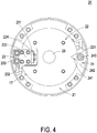
- FIG. 4 is a schematic top view illustrating the passive compliance mechanism of FIG. 3 .
- the passive compliance mechanism 20 is applied to a service robot, a collaborative robot, an industrial robot or any other appropriate robot.
- the passive compliance mechanism 20 is installed in a joint of an arm or a leg of the robot.
- the passive compliance mechanism 20 comprises a fixing member 21, a base 22, a first stiffness adjustment assembly 23 and a stiffness switching module 24.
- the fixing member 21 is assembled with the joint of the robot.
- the base 22 is installed on the fixing member 21 through a bearing (not shown).
- the base 22 is made of a flexible (or elastic) material.
- the base 22 is subjected to an elastic deformation according to the magnitude of the stiffness of the base 22. Consequently, the base 22 is moved relative to the fixing member 21. Under this circumstance, the base 22 provides the compliant function.
- the base 22 comprises a first notch 224, a second notch 221 and an elastic slice 222.
- the second notch 221 is a fan-shaped notch.
- the second notch 221 is concavely formed in the direction from an outer periphery of the base 22 to the center of the base 22.
- the elastic slice 222 is assembled with the base 22 and disposed within the first notch 224.
- the elastic slice 222 is protruded externally from the base 22 in the direction toward the outer periphery of the fixing member 21.
- a first end of the elastic slice 222 is connected with the base 22.
- a second end of the elastic slice 222 is located near the outer periphery of the fixing member 21.
- the elastic slice 222 is assembled with the base 22.
- the elastic slice 222 is integrally formed with the base 22.
- the first notch 224 is divided into two receiving spaces through the elastic slice 222.
- the first notch 224 and the second notch 221 are located at two opposite sides of the base 22.
- the first stiffness adjustment assembly 23 is installed on the fixing member 21.
- the first stiffness adjustment assembly 23 comprises a first linear guide 231, a first sliding block 232 and two first stopping blocks 233.
- the first linear guide 231 is installed on the fixing member 21. Moreover, the first linear guide 231 is aligned with the elastic slice 222.
- the first sliding block 232 is movably installed on the first linear guide 231.
- the two first stopping blocks 233 are fixedly disposed on the first sliding block 232 and synchronously moved with the first sliding block 232. Moreover, the two first stopping blocks 233 are contacted with two opposite sides of the elastic slice 222. Consequently, the elastic slice 222 is clamped by the two first stopping blocks 233.
- the stiffness of the base 22 is adjustable according to the position of the elastic slice 222 clamped by the two first stopping blocks 233. Moreover, the distance between the first end of the elastic slice 222 and the clamped position of the elastic slice 222 is an available length of the elastic slice 222.
- the magnitude of the stiffness of the base 22 is influenced by the available length of the elastic slice 222. That is, if the clamped position of the elastic slice 222 is changed, the magnitude of the stiffness of the base 22 is changed. In case that the clamped position of the elastic slice 222 is closer to the second end of the elastic slice 222, the stiffness of the base 22 is lower.
- the stiffness of the base 22 is higher.
- the two first stopping blocks 233 are moved to the first end of the elastic slice 222, the two first stopping blocks 233 are accommodated within the receiving spaces of the first notch 224, respectively.
- the first notch 224, the elastic slice 222 and the first stiffness adjustment assembly 23 are collaboratively defined as a first stiffness adjustment module.
- the first stiffness adjustment module can be used to adjust the magnitude of the stiffness of the base 22.
- the stiffness switching module 24 is installed on the fixing member 21 and aligned with the second notch 221.
- the stiffness switching module 24 comprises a second linear guide 241, a second sliding block 242 and a second stopping block 243.
- the second linear guide 241 is installed on the fixing member 21 and aligned with the second notch 221.
- the second sliding block 242 is movably installed on the second linear guide 241. Moreover, the second sliding block 242 can be moved to a first position or a second position.
- the second stopping block 243 is fixedly disposed on the second sliding block 242 and synchronously moved with the second sliding block 242.
- the second stopping block 243 is moved to the second notch 221 and engaged with the second notch 221, and thus the base 22 has the maximum stiffness. Meanwhile, even if an external force is applied to the base 22, the base 22 is not subjected to the elastic deformation because the second stopping block 243 is engaged with the second notch 221. Consequently, the base 22 is indirectly fixed on the fixing member 21. Since the base 22 is not subjected to the elastic deformation relative to the fixing member 21, the stiffness of the base 22 is similar to the stiffness of the fixing member 21. When the second sliding block 242 is moved to the second position, the second stopping block 243 is completely disengaged from the second notch 221.
- the second sliding block 242 For acquiring the maximum stiffness of the base 22, the second sliding block 242 is moved to the first position. Consequently, the second stopping block 243 is moved to the second notch 221 and engaged with the second notch 221. For dynamically adjusting stiffness of the base 22, the second sliding block 242 is moved to the second position. When the clamped position of the elastic slice 222 by the first stopping blocks 233 is changed, the magnitude of the stiffness of the base 22 is adjusted.
- the passive compliance mechanism 20 further comprises a magnetic driving module 17.
- the magnetic driving module 17 is installed on the fixing member 21 and located near the first sliding block 232.
- the magnetic driving module 17 drives the movement of the first sliding block 232 along the first linear guide 231 according to electromagnetic induction. It is noted that the way of driving the movement of the first sliding block 232 along the first linear guide 231 is not restricted.
- the use of the motor to drive to the cable rope to tow the sliding block along the linear guide is also feasible.
- the above driving method can be used to drive the stiffness switching module 24 in order to drive movement of the second sliding block 242 along the second linear guide 241.
- the passive compliance mechanism 20 further comprises a hollow pipe 29.
- the hollow pipe 29 runs the fixing member 21 and the base 22. A portion of the cable rope or any other wire of the passive compliance mechanism 20 can be wired through the hollow pipe 29. Consequently, the operation of the passive compliance mechanism 20 is not adversely affected by the cable rope or the wire.
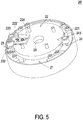
- FIG. 5 is a schematic perspective view illustrating a variant example of the passive compliance mechanism of FIG. 3 .
- the altitude of the elastic slice 222' is gradually decreased from the first end to the second end of the elastic slice 222'. Consequently, the efficacy of adjusting the stiffness by the passive compliance mechanism 20' is enhanced.
- FIG. 6 is a schematic top view illustrating another variant example of the passive compliance mechanism of FIG. 3 .
- the passive compliance mechanism 20' further comprises a second stiffness adjustment module.
- the second stiffness adjustment module comprises a first notch 224, an elastic slice 222 and a first stiffness adjustment assembly 23.
- the components, relationships and functions of the second stiffness adjustment module are similar to those of the first stiffness adjustment module, and are not redundantly described herein.
- the first stiffness adjustment module and the second stiffness adjustment module are located at two opposite sides of the fixing member 21.
- the first stiffness adjustment module and the second stiffness adjustment module are arranged near each other. The first stiffness adjustment module and the second stiffness adjustment module cooperate with each other to adjust the stiffness of the base.
- the passive compliance mechanism comprises at least three stiffness adjustment modules according to the practical requirements.
- the present invention provides the passive compliance mechanism.
- the stiffness adjustment assembly is used to adjust the stiffness of the base.
- the passive compliance mechanism can be applied to many kinds of the robots without the need of replacing any component or changing the design. For example, if the stiffness of the base is adjusted to the maximum value, the passive compliance mechanism is suitably applied to the industrial robot that requires high stiffness. If the stiffness of the base is adjusted to the lower value, the passive compliance mechanism is suitably applied to the service robot that requires high compliance. Alternatively, the passive compliance mechanism is suitably applied to the collaboratively robot that cooperates with the user. In other words, the passive compliance mechanism of the present invention is user-friendly and cost-effective.
- the passive compliance mechanism comprises plural stiffness adjustment modules.
- the sensor is used for measuring the displacement or the distortion angle of the base relative to the fixing member in response to the elastic deformation. According to the stiffness of the base and the displacement or the distortion angle of the base, the torque of the passive compliance mechanism is calculated.
Landscapes
- Engineering & Computer Science (AREA)
- Robotics (AREA)
- Mechanical Engineering (AREA)
- Manipulator (AREA)
- General Engineering & Computer Science (AREA)
- Manufacturing & Machinery (AREA)
- Quality & Reliability (AREA)
- Physics & Mathematics (AREA)
- General Physics & Mathematics (AREA)
- Automation & Control Theory (AREA)
Claims (15)
- Passiver Compliance-Mechanismus (10, 10'), umfassend:ein Befestigungselement (11);eine Basis (12), die auf dem Befestigungselement (11) installiert ist und zwei Kerben (121) und eine elastische Scheibe (122) umfasst, wobei die beiden Kerben (121) nebeneinander angeordnet sind, die elastische Scheibe (122) zwischen den beiden Kerben (121) angeordnet ist und außen von der Basis (12) in einer Richtung zu einem Außenumfang des Befestigungselements (11) vorsteht, wobei ein erstes Ende der elastischen Scheibe (122) mit der Basis (12) verbunden ist, und ein zweites Ende der elastischen Scheibe (122) nahe dem Außenumfang des Befestigungselements (11) angeordnet ist; undeine Steifigkeits-Einstellungsanordnung (13), die auf dem Befestigungselement (11) installiert ist und umfasst:eine Linearführung (131), die auf dem Befestigungselement (11) installiert und mit der elastischen Scheibe (122) ausgerichtet ist;einen Gleitblock (132), der beweglich auf der Linearführung (131) montiert ist; undzwei Anschlagblöcke (133), die fest auf dem Gleitblock (132) angeordnet und synchron mit dem Gleitblock (132) bewegbar sind, wobei die beiden Anschlagblöcke (133) mit zwei gegenüberliegenden Seiten der elastischen Scheibe (122) zum Klemmen der elastischen Scheibe (122) kontaktierbar sind und eine Steifigkeit der Basis (12) gemäß einer Klemmposition der elastischen Scheibe (122) einstellbar ist.
- Passiver Compliance-Mechanismus (10, 10') nach Anspruch 1, wobei, wenn die Klemmposition der durch die beiden Anschlagblöcke (133) eingespannten elastischen Scheibe (122) näher an dem ersten Ende der elastischen Scheibe (122) liegt, die Steifigkeit der Basis (12) höher ist, wobei, wenn die eingespannte Position der elastischen Scheibe (122), die durch die beiden Anschlagblöcke (133) eingespannt ist, näher an dem zweiten Ende der elastischen Scheibe (122) liegt, die Steifigkeit der Basis (12) geringer ist, wobei, wenn die beiden Anschlagblöcke (133) durch den Gleitblock (132) zu den beiden Kerben (121) bewegt und mit den beiden Kerben (121) in Eingriff gebracht werden, die Steifigkeit der Basis (12) den Maximalwert aufweist.
- Passiver Compliance-Mechanismus (10, 10') nach Anspruch 1 oder 2, wobei die elastische Scheibe (122) integral mit der Basis (12) ausgebildet ist, wobei eine Höhe der elastischen Scheibe (122) sich allmählich von dem ersten Ende bis zu dem zweiten Ende der elastischen Scheibe (122) verringert.
- Passiver Compliance-Mechanismus (10, 10') nach einem der vorhergehenden Ansprüche, wobei der passive Compliance-Mechanismus (10, 10') ferner ein Kabelseil (16) umfasst und das Kabelseil (16) zwischen einem Motor (15) und dem Gleitblock (132) verbunden ist, wobei, wenn das Kabelseil (16) durch den Motor (15) angetrieben wird, der Gleitblock (132) durch das Kabelseil (16) gezogen wird, so dass der Gleitblock (132) sich entlang der Linearführung (131) bewegt.
- Passiver Compliance-Mechanismus (10, 10') nach einem der vorhergehenden Ansprüche, wobei das Befestigungselement (11) ferner einen erhöhten Block (111) umfasst, und die Basis (12) ferner eine Öffnung (123) umfasst, wobei der erhöhte Block (111) durch die Öffnung (123) hindurchtritt, so dass die Basis (12) auf dem Befestigungselement (11) installiert ist, wobei der passive Compliance-Mechanismus (10, 10') weiterhin ein Hohlrohr (19) umfasst, wobei das Hohlrohr (19) durch eine Mitte des Befestigungselements (11) und eine Mitte des erhöhten Blocks (111) verläuft.
- Passiver Compliance-Mechanismus (10, 10') nach einem der vorhergehenden Ansprüche, ferner umfassend einen Sensor (14) passend zu der Basis (12), wobei der Sensor (14) auf dem Befestigungselement (11) installiert ist, um eine Verschiebung oder einen Verzugswinkel der Basis (12) gegenüber dem Befestigungselement (11) als Reaktion auf eine elastische Verformung der Basis (12) zu messen.
- Passiver Compliance-Mechanismus (10, 10') nach einem der vorhergehenden Ansprüche, wobei die beiden Kerben (121), die elastische Scheibe (122) und die Steifigkeits-Einstellungsanordnung (13) gemeinsam als ein erstes Steifigkeits-Einstellungsmodul definiert sind, und der passive Compliance-Mechanismus (10, 10') ferner ein zweites Steifigkeits-Einstellungsmodul mit der gleichen Struktur wie das erste Steifigkeits-Einstellungsmodul umfasst, wobei das erste Steifigkeits-Einstellungsmodul und das zweite Steifigkeits-Einstellungsmodul an zwei gegenüberliegenden Seiten des Befestigungselements (11) angeordnet sind, und das erste Steifigkeits-Einstellungsmodul und das zweite Steifigkeits-Einstellungsmodul miteinander zusammenarbeiten, um die Steifigkeit der Basis (12) einzustellen.
- Passiver Compliance-Mechanismus (10, 10') nach einem der vorhergehenden Ansprüche, wobei die Steifigkeits-Einstellungsanordnung (13) ferner zwei positionsbegrenzende Strukturen (134) umfasst, und die beiden positionsbegrenzenden Strukturen (134) separat auf dem Befestigungselement (11) angeordnet sind, wobei eine der beiden positionsbegrenzenden Strukturen (134) in der Nähe einer Mitte des Befestigungselements (11) angeordnet ist, und die andere der beiden positionsbegrenzenden Strukturen (134) in der Nähe des äußeren Umfangs des Befestigungselements (11) angeordnet ist, so dass ein beweglicher Bereich des Gleitblocks (132) sich durch die beiden positionsbegrenzenden Strukturen (134) bestimmt.
- Passiver Compliance-Mechanismus (10, 10') nach Anspruch 8, wobei der Gleitblock (132) ferner eine Vorstehstruktur (135) umfasst, und die Vorstehstruktur (135) aus einer Seitenfläche des Gleitblocks (132) herausragt und zwischen den beiden positionsbegrenzenden Strukturen (134) angeordnet ist, wobei der Gleitblock (132) während der Bewegung sich entlang der Linearführung (131) bewegt, wobei der bewegliche Bereich des Gleitblocks (132) durch die beiden positionsbegrenzenden Strukturen (134) durch die Vorstehstruktur (135) begrenzt ist, wobei eine Länge des beweglichen Bereichs geringfügig größer oder gleich einer Verschiebung der beiden Anschlagblöcke (133) von den beiden Kerben (121) zu dem zweiten Ende der elastischen Scheibe (122) ist.
- Passiver Compliance-Mechanismus (20, 20', 20', 20"), umfassend:ein Befestigungselement (21);eine Basis (22), die auf dem Befestigungselement (21) installiert ist und eine erste Kerbe (224), eine zweite Kerbe (221) und eine elastische Scheibe (222) umfasst, wobei die elastische Scheibe (222) auf der Basis (22) installiert ist, die innerhalb der ersten Kerbe (224) untergebracht ist, und nach außen von der Basis (22) in Richtung eines Außenumfangs des Befestigungselements (21) vorsteht, wobei ein erstes Ende der elastischen Scheibe (222) mit der Basis (22) verbunden ist und ein zweites Ende der elastischen Scheibe (222) nahe dem Außenumfang des Befestigungselements (21) angeordnet ist;eine erste Steifigkeits-Einstellungsanordnung (23), die auf dem Befestigungselement (21) installiert ist und umfasst:eine erste Linearführung (231), die auf dem Befestigungselement (21) installiert und mit der elastischen Scheibe (222) ausgerichtet ist;einen ersten Gleitblock (232), der beweglich auf der ersten Linearführung (231) montiert ist; undzwei erste Anschlagblöcke (233), die fest auf dem ersten Gleitblock (232) angeordnet und synchron mit dem ersten Gleitblock (232) bewegbar sind, wobei die beiden ersten Anschlagblöcke (233) mit zwei gegenüberliegenden Seiten der elastischen Scheibe (222) zum Klemmen der elastischen Scheibe (222) kontaktierbar sind und eine Steifigkeit der Basis (22) gemäß einer Klemmposition der elastischen Scheibe (222) einstellbar ist; undein Steifigkeits-Einstellungsmodul (24), das auf dem Befestigungselement (21) installiert ist und umfasst:eine zweite Linearführung (241), die auf dem Befestigungselement (21) montiert ist;einen zweiten Gleitblock (242), der beweglich auf der ersten Linearführung (241) installiert und selektiv in eine erste Position oder eine zweite Position bewegbar ist; undeinen zweiten Anschlagblock (243), der fest auf dem zweiten Gleitblock (242) angeordnet und synchron mit dem zweiten Gleitblock (242) bewegbar ist, wobei, wenn der zweite Gleitblock (242) sich in die erste Position bewegt, der zweite Anschlagblock (243) sich in die zweite Kerbe (221) bewegt und sich mit der zweiten Kerbe (221) in Eingriff bringt, so dass die Basis (22) die maximale Steifigkeit aufweist, wobei, wenn der zweite Gleitblock (242) sich in die zweite Position bewegt, der zweite Anschlagblock (243) sich von der zweiten Kerbe (221) löst.
- Passiver Compliance-Mechanismus (20, 20', 20"') nach Anspruch 10, wobei, wenn der zweite Gleitblock (242) sich in die zweite Position bewegt und die eingespannte Position der elastischen Scheibe (222), die durch die beiden ersten Anschlagsblöcke (233) eingespannt wird, näher an dem ersten Ende der elastischen Scheibe (222) liegt, die Steifigkeit der Basis (22) höher ist, wobei, wenn der zweite Gleitblock (242) sich in die zweite Position bewegt und die eingespannte Position der elastischen Scheibe (222), die von den beiden ersten Anschlagblöcken (233) eingespannt wird, näher an dem zweiten Ende der elastischen Scheibe (222) liegt, die Steifigkeit der Basis (22) geringer ist.
- Passiver Compliance-Mechanismus (20, 20', 20"') nach Anspruch 10 oder 11, wobei die elastische Scheibe (222) mit der Basis (22) verbunden ist, wobei eine Höhe der elastischen Scheibe (222') von dem ersten Ende bis zu dem zweiten Ende der elastischen Scheibe (222') sich allmählich verringert.
- Passiver Compliance-Mechanismus (20, 20', 20"') nach einem der Ansprüche 10-12, ferner umfassend ein magnetisches Antriebsmodul (17), wobei das magnetische Antriebsmodul (17) auf dem Befestigungselement (21) installiert und in der Nähe des ersten Gleitblocks (232) angeordnet ist, und das magnetische Antriebsmodul (17) eine Bewegung des ersten Gleitblocks (232) entlang der ersten Linearführung (231) gemäß elektromagnetischer Induktion steuert.
- Passiver Compliance-Mechanismus (20, 20', 20"') nach einem der Ansprüche 10-13, ferner umfassend ein Hohlrohr (29), wobei das Hohlrohr (29) durch das Befestigungselement (21) und die Basis (22) verläuft.
- Passiver Compliance-Mechanismus (20, 20', 20"') nach einem der Ansprüche 10-14, wobei die erste Kerbe (224), die elastische Scheibe (222) und die erste Steifigkeits-Einstellungsanordnung (23) gemeinsam als ein erstes Steifigkeits-Einstellungsmodul definiert sind, und der passive Compliance-Mechanismus (20, 20', 20"') ferner ein zweites Steifigkeits-Einstellungsmodul mit der gleichen Struktur wie das erste Steifigkeits-Einstellungsmodul umfasst, wobei das erste Steifigkeits-Einstellungsmodul und das zweite Steifigkeits-Einstellungsmodul nahe beieinander oder an zwei gegenüberliegenden Seiten des Befestigungselements (21) angeordnet sind, und das erste Steifigkeits-Einstellungsmodul und das zweite Steifigkeits-Einstellungsmodul miteinander zusammenarbeiten, um die Steifigkeit der Basis (22) einzustellen.
Priority Applications (1)
| Application Number | Priority Date | Filing Date | Title |
|---|---|---|---|
| PL17192816T PL3378609T3 (pl) | 2017-03-23 | 2017-09-25 | Pasywny mechanizm podatności |
Applications Claiming Priority (1)
| Application Number | Priority Date | Filing Date | Title |
|---|---|---|---|
| TW106109706A TWI593527B (zh) | 2017-03-23 | 2017-03-23 | 被動式順應性機構 |
Publications (2)
| Publication Number | Publication Date |
|---|---|
| EP3378609A1 EP3378609A1 (de) | 2018-09-26 |
| EP3378609B1 true EP3378609B1 (de) | 2019-07-24 |
Family
ID=59968997
Family Applications (1)
| Application Number | Title | Priority Date | Filing Date |
|---|---|---|---|
| EP17192816.1A Active EP3378609B1 (de) | 2017-03-23 | 2017-09-25 | Passiver compliance-mechanismus |
Country Status (7)
| Country | Link |
|---|---|
| US (1) | US20180275640A1 (de) |
| EP (1) | EP3378609B1 (de) |
| JP (1) | JP6571147B2 (de) |
| ES (1) | ES2748125T3 (de) |
| HU (1) | HUE044566T2 (de) |
| PL (1) | PL3378609T3 (de) |
| TW (1) | TWI593527B (de) |
Families Citing this family (7)
| Publication number | Priority date | Publication date | Assignee | Title |
|---|---|---|---|---|
| US11931888B2 (en) * | 2019-01-10 | 2024-03-19 | Ati Industrial Automation, Inc. | Robotic tool having selectable compliance modes |
| CN109732641B (zh) * | 2019-01-28 | 2021-09-07 | 西安交通大学 | 一种双态式变刚度柔顺关节及操作方法 |
| CN109807938B (zh) * | 2019-03-26 | 2020-12-29 | 清华大学 | 无导轨式变刚度驱动器 |
| CN113146674B (zh) * | 2020-01-22 | 2022-12-13 | 杭州新剑机器人技术股份有限公司 | 大柔性串联式弹性单元及包括其的机器人 |
| CN111805145B (zh) * | 2020-07-20 | 2022-05-10 | 湖南天一智能科技有限公司 | 一种夹具系统控制方法和夹具系统 |
| CN112025735A (zh) * | 2020-09-10 | 2020-12-04 | 河南工业职业技术学院 | 基于视觉感知的被动柔顺机器人抛磨装置 |
| CN113084861B (zh) * | 2021-04-20 | 2022-07-05 | 沈阳理工大学 | 一种基于永磁弹簧的串联可重构变刚度机器人关节结构 |
Family Cites Families (8)
| Publication number | Priority date | Publication date | Assignee | Title |
|---|---|---|---|---|
| KR100861953B1 (ko) * | 2007-10-05 | 2008-10-09 | 삼성전자주식회사 | 컴플라이언트 조인트 |
| KR101412130B1 (ko) * | 2008-03-14 | 2014-06-27 | 삼성전자주식회사 | 컴플라이언트 조인트 |
| KR101195700B1 (ko) * | 2010-04-05 | 2012-10-29 | 고려대학교 산학협력단 | 가변 강성 액츄에이터 유닛 |
| TW201242732A (en) * | 2011-04-19 | 2012-11-01 | Prec Machinery Res & Dev Ct | Compliance mechanism |
| CN103846930B (zh) * | 2012-12-27 | 2015-11-25 | 中国科学院合肥物质科学研究院 | 应用于服务机器人机械臂上的被动式顺应性阻抗机构 |
| WO2014176423A1 (en) * | 2013-04-24 | 2014-10-30 | Marquette University | Variable stiffness actuator with large range of stiffness |
| CN103600358A (zh) * | 2013-11-29 | 2014-02-26 | 中国科学院合肥物质科学研究院 | 一种被动式顺应性阻抗机构及机械臂 |
| CN105599004B (zh) * | 2016-03-23 | 2017-06-20 | 华南理工大学 | 一种刚度可调的机器人弹性关节 |
-
2017
- 2017-03-23 TW TW106109706A patent/TWI593527B/zh active
- 2017-09-05 US US15/695,301 patent/US20180275640A1/en not_active Abandoned
- 2017-09-25 HU HUE17192816 patent/HUE044566T2/hu unknown
- 2017-09-25 EP EP17192816.1A patent/EP3378609B1/de active Active
- 2017-09-25 JP JP2017184016A patent/JP6571147B2/ja active Active
- 2017-09-25 ES ES17192816T patent/ES2748125T3/es active Active
- 2017-09-25 PL PL17192816T patent/PL3378609T3/pl unknown
Non-Patent Citations (1)
| Title |
|---|
| None * |
Also Published As
| Publication number | Publication date |
|---|---|
| TWI593527B (zh) | 2017-08-01 |
| EP3378609A1 (de) | 2018-09-26 |
| TW201834806A (zh) | 2018-10-01 |
| JP2018158434A (ja) | 2018-10-11 |
| JP6571147B2 (ja) | 2019-09-04 |
| ES2748125T3 (es) | 2020-03-13 |
| HUE044566T2 (hu) | 2019-11-28 |
| US20180275640A1 (en) | 2018-09-27 |
| PL3378609T3 (pl) | 2019-11-29 |
Similar Documents
| Publication | Publication Date | Title |
|---|---|---|
| EP3378609B1 (de) | Passiver compliance-mechanismus | |
| US10661399B2 (en) | Single-drive rigid-flexible coupling precision motion platform and realization method and application thereof | |
| KR20140038368A (ko) | 전동 실린더 시스템 | |
| US7887032B2 (en) | Self-centering control rod | |
| US9095984B2 (en) | Force control robot | |
| KR20130138817A (ko) | 전동 실린더 및 전동 실린더 시스템 | |
| US20140167341A1 (en) | Clamping device | |
| JP2011083884A (ja) | 可変剛性機構及びロボット | |
| GB2633969A (en) | Actuator assembly | |
| US20190077029A1 (en) | Deflection element | |
| US7834517B2 (en) | Linear drive ultrasonic motor | |
| KR100396021B1 (ko) | 초정밀 이송장치 | |
| US10634698B2 (en) | High-precision scanning device | |
| CN215008895U (zh) | 折弯装置及折弯设备 | |
| JPS63156684A (ja) | ロボツトのための安全カツプリング | |
| CN113113830A (zh) | 折弯装置及折弯设备 | |
| US20110291383A1 (en) | Position adjustable coupler and hitch equipped therewith | |
| CN108621123A (zh) | 被动式顺应性机构 | |
| MY137015A (en) | Guide device for guidance of a load carrier of an elevator installation | |
| KR101398061B1 (ko) | 리니어 스테이지 | |
| KR20250081782A (ko) | 라이다 센서용 청소 시스템 | |
| CN207278705U (zh) | 用于微进给的弹性铰链结构 | |
| JP5797625B2 (ja) | リニアガイド装置及びリニアアクチュエータ装置 | |
| EP3229248A1 (de) | Druck-/zug-schaltvorrichtung | |
| JP2007303541A (ja) | 真空用位置決め装置 |
Legal Events
| Date | Code | Title | Description |
|---|---|---|---|
| PUAI | Public reference made under article 153(3) epc to a published international application that has entered the european phase |
Free format text: ORIGINAL CODE: 0009012 |
|
| STAA | Information on the status of an ep patent application or granted ep patent |
Free format text: STATUS: REQUEST FOR EXAMINATION WAS MADE |
|
| 17P | Request for examination filed |
Effective date: 20180511 |
|
| AK | Designated contracting states |
Kind code of ref document: A1 Designated state(s): AL AT BE BG CH CY CZ DE DK EE ES FI FR GB GR HR HU IE IS IT LI LT LU LV MC MK MT NL NO PL PT RO RS SE SI SK SM TR |
|
| AX | Request for extension of the european patent |
Extension state: BA ME |
|
| GRAP | Despatch of communication of intention to grant a patent |
Free format text: ORIGINAL CODE: EPIDOSNIGR1 |
|
| STAA | Information on the status of an ep patent application or granted ep patent |
Free format text: STATUS: GRANT OF PATENT IS INTENDED |
|
| INTG | Intention to grant announced |
Effective date: 20190311 |
|
| GRAS | Grant fee paid |
Free format text: ORIGINAL CODE: EPIDOSNIGR3 |
|
| GRAA | (expected) grant |
Free format text: ORIGINAL CODE: 0009210 |
|
| STAA | Information on the status of an ep patent application or granted ep patent |
Free format text: STATUS: THE PATENT HAS BEEN GRANTED |
|
| AK | Designated contracting states |
Kind code of ref document: B1 Designated state(s): AL AT BE BG CH CY CZ DE DK EE ES FI FR GB GR HR HU IE IS IT LI LT LU LV MC MK MT NL NO PL PT RO RS SE SI SK SM TR |
|
| REG | Reference to a national code |
Ref country code: GB Ref legal event code: FG4D |
|
| REG | Reference to a national code |
Ref country code: CH Ref legal event code: EP |
|
| REG | Reference to a national code |
Ref country code: DE Ref legal event code: R096 Ref document number: 602017005494 Country of ref document: DE |
|
| REG | Reference to a national code |
Ref country code: AT Ref legal event code: REF Ref document number: 1157650 Country of ref document: AT Kind code of ref document: T Effective date: 20190815 |
|
| REG | Reference to a national code |
Ref country code: IE Ref legal event code: FG4D |
|
| REG | Reference to a national code |
Ref country code: NL Ref legal event code: FP |
|
| REG | Reference to a national code |
Ref country code: HU Ref legal event code: AG4A Ref document number: E044566 Country of ref document: HU |
|
| REG | Reference to a national code |
Ref country code: SK Ref legal event code: T3 Ref document number: E 32138 Country of ref document: SK |
|
| REG | Reference to a national code |
Ref country code: LT Ref legal event code: MG4D |
|
| REG | Reference to a national code |
Ref country code: AT Ref legal event code: MK05 Ref document number: 1157650 Country of ref document: AT Kind code of ref document: T Effective date: 20190724 |
|
| PG25 | Lapsed in a contracting state [announced via postgrant information from national office to epo] |
Ref country code: AT Free format text: LAPSE BECAUSE OF FAILURE TO SUBMIT A TRANSLATION OF THE DESCRIPTION OR TO PAY THE FEE WITHIN THE PRESCRIBED TIME-LIMIT Effective date: 20190724 Ref country code: SE Free format text: LAPSE BECAUSE OF FAILURE TO SUBMIT A TRANSLATION OF THE DESCRIPTION OR TO PAY THE FEE WITHIN THE PRESCRIBED TIME-LIMIT Effective date: 20190724 Ref country code: PT Free format text: LAPSE BECAUSE OF FAILURE TO SUBMIT A TRANSLATION OF THE DESCRIPTION OR TO PAY THE FEE WITHIN THE PRESCRIBED TIME-LIMIT Effective date: 20191125 Ref country code: HR Free format text: LAPSE BECAUSE OF FAILURE TO SUBMIT A TRANSLATION OF THE DESCRIPTION OR TO PAY THE FEE WITHIN THE PRESCRIBED TIME-LIMIT Effective date: 20190724 Ref country code: NO Free format text: LAPSE BECAUSE OF FAILURE TO SUBMIT A TRANSLATION OF THE DESCRIPTION OR TO PAY THE FEE WITHIN THE PRESCRIBED TIME-LIMIT Effective date: 20191024 Ref country code: LT Free format text: LAPSE BECAUSE OF FAILURE TO SUBMIT A TRANSLATION OF THE DESCRIPTION OR TO PAY THE FEE WITHIN THE PRESCRIBED TIME-LIMIT Effective date: 20190724 Ref country code: FI Free format text: LAPSE BECAUSE OF FAILURE TO SUBMIT A TRANSLATION OF THE DESCRIPTION OR TO PAY THE FEE WITHIN THE PRESCRIBED TIME-LIMIT Effective date: 20190724 |
|
| PG25 | Lapsed in a contracting state [announced via postgrant information from national office to epo] |
Ref country code: LV Free format text: LAPSE BECAUSE OF FAILURE TO SUBMIT A TRANSLATION OF THE DESCRIPTION OR TO PAY THE FEE WITHIN THE PRESCRIBED TIME-LIMIT Effective date: 20190724 Ref country code: AL Free format text: LAPSE BECAUSE OF FAILURE TO SUBMIT A TRANSLATION OF THE DESCRIPTION OR TO PAY THE FEE WITHIN THE PRESCRIBED TIME-LIMIT Effective date: 20190724 Ref country code: GR Free format text: LAPSE BECAUSE OF FAILURE TO SUBMIT A TRANSLATION OF THE DESCRIPTION OR TO PAY THE FEE WITHIN THE PRESCRIBED TIME-LIMIT Effective date: 20191025 Ref country code: IS Free format text: LAPSE BECAUSE OF FAILURE TO SUBMIT A TRANSLATION OF THE DESCRIPTION OR TO PAY THE FEE WITHIN THE PRESCRIBED TIME-LIMIT Effective date: 20191124 Ref country code: RS Free format text: LAPSE BECAUSE OF FAILURE TO SUBMIT A TRANSLATION OF THE DESCRIPTION OR TO PAY THE FEE WITHIN THE PRESCRIBED TIME-LIMIT Effective date: 20190724 |
|
| REG | Reference to a national code |
Ref country code: ES Ref legal event code: FG2A Ref document number: 2748125 Country of ref document: ES Kind code of ref document: T3 Effective date: 20200313 |
|
| REG | Reference to a national code |
Ref country code: DE Ref legal event code: R119 Ref document number: 602017005494 Country of ref document: DE |
|
| PG25 | Lapsed in a contracting state [announced via postgrant information from national office to epo] |
Ref country code: RO Free format text: LAPSE BECAUSE OF FAILURE TO SUBMIT A TRANSLATION OF THE DESCRIPTION OR TO PAY THE FEE WITHIN THE PRESCRIBED TIME-LIMIT Effective date: 20190724 Ref country code: EE Free format text: LAPSE BECAUSE OF FAILURE TO SUBMIT A TRANSLATION OF THE DESCRIPTION OR TO PAY THE FEE WITHIN THE PRESCRIBED TIME-LIMIT Effective date: 20190724 Ref country code: DK Free format text: LAPSE BECAUSE OF FAILURE TO SUBMIT A TRANSLATION OF THE DESCRIPTION OR TO PAY THE FEE WITHIN THE PRESCRIBED TIME-LIMIT Effective date: 20190724 |
|
| PG25 | Lapsed in a contracting state [announced via postgrant information from national office to epo] |
Ref country code: IS Free format text: LAPSE BECAUSE OF FAILURE TO SUBMIT A TRANSLATION OF THE DESCRIPTION OR TO PAY THE FEE WITHIN THE PRESCRIBED TIME-LIMIT Effective date: 20200224 Ref country code: SM Free format text: LAPSE BECAUSE OF FAILURE TO SUBMIT A TRANSLATION OF THE DESCRIPTION OR TO PAY THE FEE WITHIN THE PRESCRIBED TIME-LIMIT Effective date: 20190724 Ref country code: MC Free format text: LAPSE BECAUSE OF FAILURE TO SUBMIT A TRANSLATION OF THE DESCRIPTION OR TO PAY THE FEE WITHIN THE PRESCRIBED TIME-LIMIT Effective date: 20190724 |
|
| PLBE | No opposition filed within time limit |
Free format text: ORIGINAL CODE: 0009261 |
|
| STAA | Information on the status of an ep patent application or granted ep patent |
Free format text: STATUS: NO OPPOSITION FILED WITHIN TIME LIMIT |
|
| PG2D | Information on lapse in contracting state deleted |
Ref country code: IS |
|
| PG25 | Lapsed in a contracting state [announced via postgrant information from national office to epo] |
Ref country code: DE Free format text: LAPSE BECAUSE OF NON-PAYMENT OF DUE FEES Effective date: 20200401 Ref country code: LU Free format text: LAPSE BECAUSE OF NON-PAYMENT OF DUE FEES Effective date: 20190925 Ref country code: IE Free format text: LAPSE BECAUSE OF NON-PAYMENT OF DUE FEES Effective date: 20190925 |
|
| 26N | No opposition filed |
Effective date: 20200603 |
|
| PG25 | Lapsed in a contracting state [announced via postgrant information from national office to epo] |
Ref country code: SI Free format text: LAPSE BECAUSE OF FAILURE TO SUBMIT A TRANSLATION OF THE DESCRIPTION OR TO PAY THE FEE WITHIN THE PRESCRIBED TIME-LIMIT Effective date: 20190724 |
|
| PG25 | Lapsed in a contracting state [announced via postgrant information from national office to epo] |
Ref country code: FR Free format text: LAPSE BECAUSE OF NON-PAYMENT OF DUE FEES Effective date: 20190930 |
|
| REG | Reference to a national code |
Ref country code: CH Ref legal event code: PL |
|
| PG25 | Lapsed in a contracting state [announced via postgrant information from national office to epo] |
Ref country code: CY Free format text: LAPSE BECAUSE OF FAILURE TO SUBMIT A TRANSLATION OF THE DESCRIPTION OR TO PAY THE FEE WITHIN THE PRESCRIBED TIME-LIMIT Effective date: 20190724 |
|
| PG25 | Lapsed in a contracting state [announced via postgrant information from national office to epo] |
Ref country code: MT Free format text: LAPSE BECAUSE OF FAILURE TO SUBMIT A TRANSLATION OF THE DESCRIPTION OR TO PAY THE FEE WITHIN THE PRESCRIBED TIME-LIMIT Effective date: 20190724 |
|
| PG25 | Lapsed in a contracting state [announced via postgrant information from national office to epo] |
Ref country code: LI Free format text: LAPSE BECAUSE OF NON-PAYMENT OF DUE FEES Effective date: 20200930 Ref country code: CH Free format text: LAPSE BECAUSE OF NON-PAYMENT OF DUE FEES Effective date: 20200930 |
|
| GBPC | Gb: european patent ceased through non-payment of renewal fee |
Effective date: 20210925 |
|
| PG25 | Lapsed in a contracting state [announced via postgrant information from national office to epo] |
Ref country code: MK Free format text: LAPSE BECAUSE OF FAILURE TO SUBMIT A TRANSLATION OF THE DESCRIPTION OR TO PAY THE FEE WITHIN THE PRESCRIBED TIME-LIMIT Effective date: 20190724 |
|
| PG25 | Lapsed in a contracting state [announced via postgrant information from national office to epo] |
Ref country code: GB Free format text: LAPSE BECAUSE OF NON-PAYMENT OF DUE FEES Effective date: 20210925 |
|
| PGFP | Annual fee paid to national office [announced via postgrant information from national office to epo] |
Ref country code: NL Payment date: 20250926 Year of fee payment: 9 Ref country code: TR Payment date: 20250908 Year of fee payment: 9 Ref country code: PL Payment date: 20250904 Year of fee payment: 9 Ref country code: IT Payment date: 20250919 Year of fee payment: 9 |
|
| PGFP | Annual fee paid to national office [announced via postgrant information from national office to epo] |
Ref country code: BE Payment date: 20250929 Year of fee payment: 9 Ref country code: BG Payment date: 20250917 Year of fee payment: 9 Ref country code: HU Payment date: 20250910 Year of fee payment: 9 |
|
| PGFP | Annual fee paid to national office [announced via postgrant information from national office to epo] |
Ref country code: CZ Payment date: 20250908 Year of fee payment: 9 |
|
| PGFP | Annual fee paid to national office [announced via postgrant information from national office to epo] |
Ref country code: SK Payment date: 20250903 Year of fee payment: 9 |
|
| PGFP | Annual fee paid to national office [announced via postgrant information from national office to epo] |
Ref country code: ES Payment date: 20251001 Year of fee payment: 9 |