EP3378621A1 - Outil à étages - Google Patents
Outil à étages Download PDFInfo
- Publication number
- EP3378621A1 EP3378621A1 EP18163226.6A EP18163226A EP3378621A1 EP 3378621 A1 EP3378621 A1 EP 3378621A1 EP 18163226 A EP18163226 A EP 18163226A EP 3378621 A1 EP3378621 A1 EP 3378621A1
- Authority
- EP
- European Patent Office
- Prior art keywords
- mold
- holding parts
- block
- cavities
- center block
- Prior art date
- Legal status (The legal status is an assumption and is not a legal conclusion. Google has not performed a legal analysis and makes no representation as to the accuracy of the status listed.)
- Granted
Links
Images


Classifications
-
- B—PERFORMING OPERATIONS; TRANSPORTING
- B29—WORKING OF PLASTICS; WORKING OF SUBSTANCES IN A PLASTIC STATE IN GENERAL
- B29C—SHAPING OR JOINING OF PLASTICS; SHAPING OF MATERIAL IN A PLASTIC STATE, NOT OTHERWISE PROVIDED FOR; AFTER-TREATMENT OF THE SHAPED PRODUCTS, e.g. REPAIRING
- B29C45/00—Injection moulding, i.e. forcing the required volume of moulding material through a nozzle into a closed mould; Apparatus therefor
- B29C45/16—Making multilayered or multicoloured articles
- B29C45/1615—The materials being injected at different moulding stations
- B29C45/162—The materials being injected at different moulding stations using means, e.g. mould parts, for transferring an injected part between moulding stations
-
- B—PERFORMING OPERATIONS; TRANSPORTING
- B29—WORKING OF PLASTICS; WORKING OF SUBSTANCES IN A PLASTIC STATE IN GENERAL
- B29C—SHAPING OR JOINING OF PLASTICS; SHAPING OF MATERIAL IN A PLASTIC STATE, NOT OTHERWISE PROVIDED FOR; AFTER-TREATMENT OF THE SHAPED PRODUCTS, e.g. REPAIRING
- B29C45/00—Injection moulding, i.e. forcing the required volume of moulding material through a nozzle into a closed mould; Apparatus therefor
- B29C45/17—Component parts, details or accessories; Auxiliary operations
- B29C45/26—Moulds
- B29C45/32—Moulds having several axially spaced mould cavities, i.e. for making several separated articles
-
- B—PERFORMING OPERATIONS; TRANSPORTING
- B29—WORKING OF PLASTICS; WORKING OF SUBSTANCES IN A PLASTIC STATE IN GENERAL
- B29C—SHAPING OR JOINING OF PLASTICS; SHAPING OF MATERIAL IN A PLASTIC STATE, NOT OTHERWISE PROVIDED FOR; AFTER-TREATMENT OF THE SHAPED PRODUCTS, e.g. REPAIRING
- B29C45/00—Injection moulding, i.e. forcing the required volume of moulding material through a nozzle into a closed mould; Apparatus therefor
- B29C45/16—Making multilayered or multicoloured articles
- B29C45/1615—The materials being injected at different moulding stations
- B29C2045/1617—The materials being injected at different moulding stations using stack moulds
-
- B—PERFORMING OPERATIONS; TRANSPORTING
- B29—WORKING OF PLASTICS; WORKING OF SUBSTANCES IN A PLASTIC STATE IN GENERAL
- B29C—SHAPING OR JOINING OF PLASTICS; SHAPING OF MATERIAL IN A PLASTIC STATE, NOT OTHERWISE PROVIDED FOR; AFTER-TREATMENT OF THE SHAPED PRODUCTS, e.g. REPAIRING
- B29C45/00—Injection moulding, i.e. forcing the required volume of moulding material through a nozzle into a closed mould; Apparatus therefor
- B29C45/03—Injection moulding apparatus
- B29C45/04—Injection moulding apparatus using movable moulds or mould halves
- B29C45/0441—Injection moulding apparatus using movable moulds or mould halves involving a rotational movement
- B29C45/045—Injection moulding apparatus using movable moulds or mould halves involving a rotational movement mounted on the circumference of a rotating support having a rotating axis perpendicular to the mould opening, closing or clamping direction
-
- B—PERFORMING OPERATIONS; TRANSPORTING
- B29—WORKING OF PLASTICS; WORKING OF SUBSTANCES IN A PLASTIC STATE IN GENERAL
- B29C—SHAPING OR JOINING OF PLASTICS; SHAPING OF MATERIAL IN A PLASTIC STATE, NOT OTHERWISE PROVIDED FOR; AFTER-TREATMENT OF THE SHAPED PRODUCTS, e.g. REPAIRING
- B29C45/00—Injection moulding, i.e. forcing the required volume of moulding material through a nozzle into a closed mould; Apparatus therefor
- B29C45/16—Making multilayered or multicoloured articles
- B29C45/1615—The materials being injected at different moulding stations
- B29C45/1628—The materials being injected at different moulding stations using a mould carrier rotatable about an axis perpendicular to the opening and closing axis of the moulding stations
Definitions
- the present invention relates to a stack mold for an injection molding apparatus, the stack mold comprising a center block and first and second outer mold blocks.
- the center block and the first and second outer mold blocks are, preferably linearly to each other, adjustable between a closed position and an open position.
- the outer mold blocks have outer cavities on their side facing the central block.
- the center block comprises inner cavities on its sides facing the outer mold blocks.
- the outer cavities cooperate in the closed position with the inner cavities to form mold cavities, wherein at least a portion of the mold cavities formed by adjustable holding parts, which with respect to a rotation axis, in particular circular, are completely movable around the center block.
- Stacking tools are used in injection molding machines to achieve high throughput because in the closed position, both injection molding in the mold cavities between the first outer mold block and the center block and in the mold cavities between the second outer mold block and the center block are possible simultaneously is.
- the articles to be created are held by the adjustable holding members after injection molding and can be moved around the center block by the holding members.
- the object is achieved by a stack mold according to the first independent claim (claim 1) and in particular by the fact that the stack mold comprises at least two holding parts, which can be arranged at the same time on the same side of the center block.
- the stack mold comprises at least two holding parts, which can be arranged at the same time on the same side of the center block.
- at least two holding parts are provided which can be arranged or arranged simultaneously between the center block and the same outer forming block.
- the stack tool can also have four holding parts or exactly four holding parts, of which two are arranged at the same time on the same side of the center block. This makes it possible that two holding parts between the first outer mold block and the center block and two further holding parts between the second outer mold block and the center block are arranged.
- the central block can thus form two "active surfaces" for injection molding together with the outer mold blocks.
- the active surfaces are the surfaces on which the mold cavities are formed.
- injection molding of a first component may occur at the active area between the first outer mold block and the middle block.
- the injection molded parts or molded parts which then only consist of one component, can now be rotated through 180 ° about the central block.
- a second component can be added to the moldings on the active surface between the second outer mold block and the middle block, so that two-component injection-molded parts can be produced in a simple manner, wherein at the same time a high throughput can be achieved.
- the holding parts are moved only in steps of 180 ° about the middle block with respect to the axis of rotation around.
- smaller increments are possible, for example 45 ° or 90 ° steps.
- it is possible to move the holding parts after injection molding for example, by 45 ° or 90 ° and eject the moldings or moldings at this position.
- it is possible to add additional parts to the moldings in the 45 ° or 90 ° position for example by placing a label made of paper or plastic on the injection molding.
- the additional parts can also be attached between the center block and the outer mold blocks on the moldings, for example, with a gripper arm, the additional parts to the between middle block and outer mold blocks located injection molds are attached.
- a functional station may be provided in the active surface, wherein, for example, the additional parts may be added to the molded parts or molded parts in the functional station.
- the center block and the outer mold blocks are each formed cuboid or cuboid.
- other geometric shapes are conceivable, such as polyhedra.
- block is to be understood not only as a solid or approximately massive block, instead the term block should be understood as meaning that a predetermined area of space is occupied or bounded by the respective block.
- the center block comprises six outer surfaces, with two opposite side surfaces defining the active surfaces and facing the outer mold blocks.
- the top and bottom of the center block can be penetrated by the axis of rotation.
- the articles or moldings to be produced with the stack mold may be e.g. to act toothbrushes, handles for razors and / or handles for screwdrivers and the like.
- Such injection-molded parts are usually produced from more than one material component.
- the axis of rotation is centrally located in the center block and / or a bogie is provided which rotates about the axis of rotation and moves the holding parts around the central block.
- the holding parts may be attached to the bogie.
- the bogie can rotate about the axis of rotation and the holding parts circular about the axis of rotation and thus also move around the middle block. All or at least the holding parts fastened to the bogie thus preferably rotate about the same axis of rotation.
- the axis of rotation may extend, for example, through a diagonal intersection of the top and / or bottom of the middle block.
- the axis of rotation may preferably extend vertically through the center block.
- the holding parts can each be moved past the side surfaces of the center block.
- the bogie can be rotatably mounted on the top and / or bottom of the center block. The bogie is advantageously designed to move the holding parts 360 ° around the central block.
- the bogie extends both above and below the middle block.
- the holding parts can be both above and below the middle block of the bogie be attached and / or held, resulting in increased stability of the holding parts.
- the sections of the bogie, which are located above and below the central block may be connected by a, in particular vertical, shaft, so that a synchronous drive of the bogie is ensured both above and below the center block.
- a drive may be provided, which drives the respective sections of the bogie, which are located above and below the center block.
- the bogie comprises a pivot bearing, which is arranged in the top of the center block.
- the bogie may also include a pivot bearing in the bottom of the center block.
- the pivot bearing may have a, in particular by means of ball bearings mounted rotary ring.
- the pivot bearings may define an opening in the top and / or bottom of the center block, so that other components - as stated later - can be mounted within the pivot bearing on the center block.
- the holding parts are permanently coupled to the bogie. This means that the holding parts are not detachable from the bogie, so that the holding parts are always moved with a rotation of the bogie with the bogie. An elaborate mechanism for coupling and uncoupling the holding parts can be saved in this way.
- the bogie comprises at least one pair of rails, which slidably attached one of the holding parts.
- a pair of rails is provided for each attached to the bogie holding part, wherein in each case a pair of rails is assigned to exactly one holding part and that holding part slidably attached.
- the pair of rails may comprise two mutually parallel rails.
- the pairs of rails go out of the rotary ring of the pivot bearing.
- pairs of rails may emerge from the turning ring on the top of the center block and secure the holding parts in the area of the top of the center block.
- pairs of rails may be part of the bogie, which are arranged on the underside of the center block and, for example, emerge from the rotary ring of the pivot bearing on the underside of the center block.
- the holding parts can be kept very safe in this way, namely at their respective upper and lower ends.
- the stack tool comprises at least four (or exactly four) holding parts, of which each two opposite each other with respect to the center block.
- the positions of the holding parts relative to the Rotational axis to be axisymmetric. This makes it possible to arrange in each case two holding parts on an active surface and two further holding parts on the opposite active surface.
- molded parts or molded parts can be formed simultaneously on both active surfaces, ie in both "floors".
- the respective longitudinal direction of the holding parts is parallel to each other.
- the holding parts can be arranged at a distance from each other but at the same time have the same orientation in space.
- the longitudinal direction of the holding parts can run parallel to the axis of rotation and / or vertically.
- the stack mold comprises at least one lifting device which is designed to move the holding parts away from the middle block and / or to approximate the middle block, wherein the lifting device is preferably decoupled from the holding parts during a rotation of the holding parts about the axis of rotation.
- the holding parts may include a coupling portion which engages in a receiving portion of the lifting device to provide an operative connection between the lifting device and the holding part.
- the lifting device may comprise two receiving portions, which are arranged in the region of the top and bottom of the center block. Each receiving section may be separated by a separate mechanical actuator, e.g. a servomotor, to be moved.
- the holding parts can comprise a first coupling section at a first (upper) end and a second coupling section at a second (lower) end.
- the receiving portion and the coupling portion may be formed such that the operative connection automatically is then produced when the holding parts between the center block and the first or second outer mold block are arranged.
- the receiving portion for example, have a curved groove, so that the coupling portion, which is moved in a circle around the center block, can enter into the receiving portion.
- the lifting device or devices are stationary and e.g. attached to the middle block.
- the lifting device (s) within the rotary ring of the pivot bearing can not be rotatably attached to the center block.
- a separate lifting device is provided for each holding part.
- the number of lifting devices corresponds to the number of holding parts.
- the flexibility of operations in the use of the stack tool can be improved because each holding part can also be moved separately by the separate lifting device.
- injection-molded parts on a first holding part can hereby be lifted out of the mold cavities earlier than injection-molded parts on a second holding part. In this way, e.g. realize different cooling times for different injection molded parts.
- the lifting device is designed to move the holding parts perpendicular to the respective side of the center block.
- the lifting device thus makes it possible to approach or remove the holding part from the respectively closest side of the middle block in the direction of a normal to the respective side of the middle block.
- the middle block recesses for example in cuboid or trench form, comprise for the holding parts, wherein the holding parts can be lifted out of the respective recess by the lifting device.
- the depressions may be part of the inner cavities.
- both the holding parts and the depressions may have a wedge shape.
- the wedge shape may taper toward the interior of the center block.
- the holding parts may preferably be elongate and cuboid with a flat cross-section. Narrow sides of the holding parts preferably have holding cavities along the longitudinal direction of the holding parts, which cavities form the mold cavities together with the inner and outer cavities.
- the retaining cavities may serve to hold the moldings, particularly in the open position and when moving the holding members around the center block.
- the holding parts of the lifting device are movable in a direction which deviates from a radial direction with respect to the axis of rotation.
- the support members are not lifted radially (with respect to the axis of rotation) out of the surfaces of the center block, but only normally, i.e. due to their offset. perpendicular.
- the rails of the pairs of rails extend in a direction perpendicular to the two surfaces of the center block, on which the inner cavities are arranged, ie in particular perpendicular to the active surfaces.
- the rails and also the rotary ring of the pivot bearing preferably extend parallel to the top and / or bottom of the center block.
- the rotary ring is arranged in each case adjacent to the top and / or bottom of the center block.
- the rails of the rail pairs advantageously do not extend in a radial direction with respect to the axis of rotation, but are arranged so that the pairs of rails allow movement of the holding parts along a perpendicular to the nearest surface or surfaces of the center block.
- the lifting of the holding parts or the moving away of the holding parts from the center block creates a space between the holding parts and the center block, which makes it possible to move the holding parts around the middle block without the holding parts abutting the edges of the middle block.
- the holding parts comprise carriages which allow movement of the holding parts by means of the lifting device, the carriages being e.g. are slidably mounted on or on the bogie and in particular on or on one of the rail pairs.
- the carriages can be formed for example by a return.
- the bogie between the axis of rotation and the holding parts at least partially Y-shaped, in particular with two arms formed.
- the Y-shape can make a connection between the pairs of rails and the axis of rotation and give the bogie in this way additional mechanical stability.
- the Y-shaped section is preferably arranged only above the middle block.
- the rails of the pairs of rails can be coupled by means of a U-shaped connector with the arms of the Y-shaped portion of the bogie.
- the rails are located adjacent to the middle block at its top and bottom.
- the Y-shaped portion of the bogie is spaced from the rails, with the lift (s) disposed between the rails and the Y-shaped portion, for example.
- At least one of the holding parts comprises cavities through which a coolant is guided.
- all holding parts comprise cavities through which the coolant flows.
- the inner and / or outer cavities can also comprise cooling and can also be cooled by coolant. The coolant can accelerate cooling of the injection molded parts can be achieved, whereby the duration of process cycles of the stack mold can be shortened.
- At least one of the holding parts is rotatably supported such that the rotatable holding part is set up to turn two, in particular opposite, surfaces of the holding part on the same side of the middle block.
- all holding parts can be rotatably mounted in the aforementioned manner.
- the holding parts may, for example, be rotatable about a holding part axis, wherein the holding part axis extends along the longitudinal direction of the holding parts and preferably parallel to the axis of rotation. Due to the double rotation of the holding parts, namely on the one hand to the middle block and on the other hand to itself, the implementation of many different processes is allowed by means of the stack tool. As a result, the flexibility of the use of the floor tool is further increased. For example, injection-molded parts can first be sprayed with a first component, wherein the injection-molded parts are held only on a narrow side of a holding part.
- the injection-molded parts can remain in the same active area of the center block but can be spent, for example, in other mold cavities.
- a second component can be added to the moldings, which for example partially encloses the first component.
- a third component can then be sprayed on the second active surface and a fourth component can be injected around the retaining part axis after only the retaining part has been turned again.
- the holding parts by means of an additional pivot bearing on the pairs of rails can be mounted slidably and at the same time rotatable.
- the holding parts can comprise laterally displaceable squeegee strips (which are perpendicular to the holding part axis) which lift the injection-molded parts laterally out of the holding parts, after which the injection-molded parts can fall, for example, into a collecting container below the stack mold.
- the invention also includes a stack mold according to the second independent claim.
- the object of the invention is achieved in that at least one of the holding parts is rotatably mounted such that the rotatable holding part is adapted to turn two, in particular opposite, surfaces of the holding part of the same side of the center block.
- the stack mold comprises two holding parts and preferably exactly two holding parts.
- the rotation of the holding parts about a holding part axis allows additional flexibility in the processes that can be carried out with the stack mold.
- At least one of the holding parts is movable away in a direction away from the middle block, which deviates from a radial direction with respect to the axis of rotation.
- the holding parts can thus be e.g. be offset from a center position with respect to a side of the center block, so that results in an asymmetrical position. Due to the asymmetric position, for example, particularly long injection-molded parts can be formed, since the distance between the holding part and the distal end of the active surface of the center block is particularly large.
- the bogie may have a Z-shaped section when e.g. two holding parts are used for opposite surfaces of the center block. Incidentally, the Z-shaped portion may have the same characteristics as the above-mentioned Y-shaped portion.
- the two holding parts are arranged in particular axially symmetrical to the axis of rotation.
- the rails of the pairs of rails which fix the respective holding part displaceable, may also be formed axially symmetrical to the axis of rotation.
- the rails preferably do not extend radially to the axis of rotation. Instead, the rails may be perpendicular to the active surfaces.
- the invention relates to an injection molding with a stack tool of the type described above.
- the invention relates to a method which is carried out with a stack mold according to the first independent claim.
- the method comprises making molds from a first component (i.e., a first material) in the mold cavities between the first outer mold block and the middle block.
- the created injection molded parts are then held by means of the holding parts and moved by means of the bogie at the holding parts by 180 ° around the middle block around.
- the moldings in the mold cavities between the second outer mold block and the center block are at least partially overmoulded with a second component (i.e., with a second material different from the first material).
- the invention also relates to a method which is carried out with a stack mold according to the second independent claim.
- the method comprises making molds from a first component (i.e., a first material) in the mold cavities between the first outer mold block and the middle block.
- the created injection-molded parts are then rotated about the holding part axis by means of the holding part.
- the injection-molded parts are in turn in the mold cavities between the first outer mold block and the center block at least partially overmolded with a second component (i.e., with a different material from the first material).
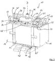
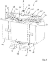
- Fig. 1 shows a first embodiment of a stack mold 10 which is used in an injection molding apparatus or injection molding machine (not shown).
- the stack mold 10 includes a middle block 12, a first outer mold block 14, and a second outer mold block 16.
- the center block 12 is supported on a bearing block 18.
- the outer mold blocks 14, 16 are linearly movable relative to the center block 12.
- Fig. 1 the stack mold 10 is shown in a closed position. This means that the outer mold blocks 14, 16 are moved up to the center block 12 and form in this way a continuous unit or a uniform block.
- the stack mold 10 is in the open position, in which there is a gap between the center block 12 and the outer mold blocks 14, 16. This distance is achieved by a linear displacement of the center block 12 and the second outer mold block 16 away from the first outer mold block 14.
- the center block 12 has inner cavities 20 which cooperate with outer cavities 22 of the outer mold blocks 14, 16 to jointly form mold cavities for injection molding.
- outer cavities 22 are in Fig. 2 only those of the first outer mold block 14 can be seen.
- the first outer mold block 14 and the second outer mold block 16 are constructed symmetrically to the middle block 12.
- the sides of the center block 12, which include inner cavities 20, face each other with respect to the center block 12 and form respective active surfaces 24.
- the holding members 26 Adjacent to the active surfaces 24 four holding parts 26 are arranged, of which in the Fig. 2 only three are visible.
- the holding members 26 include retaining cavities 28 which define the mold cavities together with the inner and outer cavities 20, 22 and, after injection of moldings 30, serve to hold the injection moldings 30.
- two of the holding parts 26 are at the same time arranged on the same side of the central block 12, ie are adjacent to the same active surface 24th
- the holding parts 26 are movable in a vertical direction away from the active surface 24, so that they correspond to the in Fig. 2 can take position shown. However, the holding parts 26 can also be moved into the active surfaces 24, so that the holding cavities 28 interact with the inner cavities 20 and the outer cavities 22, to form the mold cavities. If the holding parts 26 are retracted into the active surfaces 24, the holding parts 26 are in cuboid depressions 31, which extend between the inner cavities 20. The cuboid recesses 31 are dimensioned so that the holding parts 26 are mounted as free of play.
- the holding parts 26 each comprise at their ends in the longitudinal direction two recesses 32, which are mounted on rails 34 and thus enable a sliding displacement of the holding members 26 perpendicular to the center block 12.
- the holding parts 26 also comprise a slide section 36, which is respectively arranged between two rails 34 and guides the holding parts 26.
- the rails 34 are parallel to each other, with two rails 34 each form a pair of rails.
- On the carriage portion 36 a projection 38 is arranged in each case, which engages in a groove 40 of an adjusting element 42.
- the adjusting element 42 is coupled to a respective lifting drive 44, which allows the movement of the holding parts 26 independently of each other by means of a threaded spindle 45.
- a separate lifting drive 44 and a separate adjusting element 42 per holding part 26 are provided in each case.
- two lifting drives 44 and two adjusting elements 42 together form a lifting device for the respective holding part 26.
- Each holding part 26 comprises in a corresponding manner two slide sections 36 and two projections 38 which respectively engage the grooves 40 of the adjusting elements 42 at the top and bottom.
- the holding parts 26 can be rotated about their respective holding part axis H, in particular by 360 °.
- the holding sub-axes H are parallel to the axis of rotation D. The rotation of the holding parts 26 results in additional possibilities in the design of process sequences.
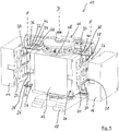
- Fig. 3 are the holding members 26 in the open position of the stack tool 10 about 45 ° rotated about a central axis of rotation D.
- the central axis of rotation D is centrally located in the middle block 12 and penetrates the center block 12 in the vertical direction.
- the bogie 46 comprises at the top of the center block 12 and at the bottom of the center block 12 each have a pivot bearing 48 to which the rails 34 are attached, so that upon rotation of the pivot bearing 48 and the rails 34 and thus also on the rails 34th slidably mounted holding members 26 are movable around the center block 12 around.
- pivot bearing 48 is a non-rotatable, connected to the center block 12, circular cover plate 50 is provided. Below the cover plate 50 and within the pivot bearing 48, the lifting actuators 44 and the adjusting elements 42 are attached to the center block 12. Upon rotation of the pivot bearing 48 and the bogie 46, the lifting actuators 44 and the adjusting elements 42 remain in their position.
- a coolant distributor 52 is arranged, which are each connected via Y-shaped struts 54 with U-shaped holders 56.
- the U-shaped holders 56 are respectively attached to two of the rails 34.
- the coolant manifold 52 may facilitate water cooling of the retainers 26 via flexible cooling hoses (not shown) coupled to the support members 26.
- the holding parts 26 may first be retracted into the active surfaces 24 in order to form mold cavities with the inner and outer cavities 20, 22.
- the center block 12 and the outer mold blocks 14, 16 are brought into the closed position, whereupon material of a first component is injected into the mold cavities to form the moldings 30.
- the stack mold 10 is moved to the open position, whereupon the holding members 26 are moved away from the middle block 12 with the injection moldings 30 secured in the holding members 26 injection moldings 30.
- the bogie 46 for example, perform a 180 ° rotation, so that the moldings 30 can now be further processed on the other active surface 24, for example by the additional spraying of a second component.
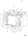
- a second embodiment of the stack mold 10 is shown.
- the second embodiment differs from the first embodiment according to FIG Fig. 1 to 3 in that a total of only two holding parts 26 are provided.
- the holding parts 26 are each supported asymmetrically with respect to the active surfaces 24, so that the coolant distributor 52 is not coupled to the rails 34 via Y-shaped struts 54 but via Z-shaped struts 58.
- Fig. 4 the second embodiment of the stack mold 10 is shown in the closed position. It can be seen that a total of only two lifting devices comprising two lifting drives 44 and two adjusting elements 42 are provided.
- the stack mold 10 comprises four pairs of rails each consisting of two parallel rails 34.
- each four rails 34 attach a holding part 26.
- the two holding parts 26 are each held asymmetrically to the active surfaces 24 but axially symmetrical to the axis of rotation D.
- Fig. 6 shows in analogy to Fig. 3 the rotation of the holding parts 26 by means of the bogie 46. Incidentally, the statements made for the first embodiment apply to the second embodiment accordingly.
Landscapes
- Engineering & Computer Science (AREA)
- Manufacturing & Machinery (AREA)
- Mechanical Engineering (AREA)
- Moulds For Moulding Plastics Or The Like (AREA)
- Injection Moulding Of Plastics Or The Like (AREA)
Applications Claiming Priority (1)
| Application Number | Priority Date | Filing Date | Title |
|---|---|---|---|
| DE102017106179.7A DE102017106179A1 (de) | 2017-03-22 | 2017-03-22 | Etagenwerkzeug |
Publications (2)
| Publication Number | Publication Date |
|---|---|
| EP3378621A1 true EP3378621A1 (fr) | 2018-09-26 |
| EP3378621B1 EP3378621B1 (fr) | 2021-05-19 |
Family
ID=61749985
Family Applications (1)
| Application Number | Title | Priority Date | Filing Date |
|---|---|---|---|
| EP18163226.6A Active EP3378621B1 (fr) | 2017-03-22 | 2018-03-22 | Outil à étages |
Country Status (2)
| Country | Link |
|---|---|
| EP (1) | EP3378621B1 (fr) |
| DE (1) | DE102017106179A1 (fr) |
Cited By (2)
| Publication number | Priority date | Publication date | Assignee | Title |
|---|---|---|---|---|
| CN110653990A (zh) * | 2018-12-24 | 2020-01-07 | 上海紫丹食品包装印刷有限公司 | 一种射出成型机及注塑成型工艺 |
| CN110653991A (zh) * | 2018-12-24 | 2020-01-07 | 上海紫丹食品包装印刷有限公司 | 一种用于射出成型机的转模台 |
Citations (6)
| Publication number | Priority date | Publication date | Assignee | Title |
|---|---|---|---|---|
| US4427359A (en) * | 1981-07-14 | 1984-01-24 | Sumitomo Heavy Industries, Ltd. | Injection stretch-blow molding machine |
| US20040094866A1 (en) * | 2002-11-18 | 2004-05-20 | Boucherie Bart Gerard | Method and device for manufacturing injection molding pieces |
| US20060153947A1 (en) * | 2005-01-11 | 2006-07-13 | Shakal Wayne A | Rotary automatic transfer rail for injection molding |
| WO2007055607A2 (fr) * | 2005-11-11 | 2007-05-18 | Plasdan - Projectos Industriais Para A Indústria De Plásticos, S.A. | Systeme de soutien interchangeable pour moules d'injection multi-composants |
| WO2007082394A1 (fr) * | 2006-01-23 | 2007-07-26 | Foboha Gmbh Formenbau | Systeme de transfert pour moulage par injection a plusieurs composants |
| WO2007085063A1 (fr) * | 2006-01-27 | 2007-08-02 | Firma G.B. Boucherie, Naamloze Vennootschap | Dispositif destiné à la fabrication de pièces moulées par injection |
Family Cites Families (1)
| Publication number | Priority date | Publication date | Assignee | Title |
|---|---|---|---|---|
| EP2324981B1 (fr) | 2009-11-19 | 2015-10-07 | G.B. Boucherie, N.V. | Outil de moulage par injection |
-
2017
- 2017-03-22 DE DE102017106179.7A patent/DE102017106179A1/de not_active Withdrawn
-
2018
- 2018-03-22 EP EP18163226.6A patent/EP3378621B1/fr active Active
Patent Citations (6)
| Publication number | Priority date | Publication date | Assignee | Title |
|---|---|---|---|---|
| US4427359A (en) * | 1981-07-14 | 1984-01-24 | Sumitomo Heavy Industries, Ltd. | Injection stretch-blow molding machine |
| US20040094866A1 (en) * | 2002-11-18 | 2004-05-20 | Boucherie Bart Gerard | Method and device for manufacturing injection molding pieces |
| US20060153947A1 (en) * | 2005-01-11 | 2006-07-13 | Shakal Wayne A | Rotary automatic transfer rail for injection molding |
| WO2007055607A2 (fr) * | 2005-11-11 | 2007-05-18 | Plasdan - Projectos Industriais Para A Indústria De Plásticos, S.A. | Systeme de soutien interchangeable pour moules d'injection multi-composants |
| WO2007082394A1 (fr) * | 2006-01-23 | 2007-07-26 | Foboha Gmbh Formenbau | Systeme de transfert pour moulage par injection a plusieurs composants |
| WO2007085063A1 (fr) * | 2006-01-27 | 2007-08-02 | Firma G.B. Boucherie, Naamloze Vennootschap | Dispositif destiné à la fabrication de pièces moulées par injection |
Cited By (3)
| Publication number | Priority date | Publication date | Assignee | Title |
|---|---|---|---|---|
| CN110653990A (zh) * | 2018-12-24 | 2020-01-07 | 上海紫丹食品包装印刷有限公司 | 一种射出成型机及注塑成型工艺 |
| CN110653991A (zh) * | 2018-12-24 | 2020-01-07 | 上海紫丹食品包装印刷有限公司 | 一种用于射出成型机的转模台 |
| CN110653990B (zh) * | 2018-12-24 | 2024-04-02 | 上海紫丹食品包装印刷有限公司 | 一种射出成型机及注塑成型工艺 |
Also Published As
| Publication number | Publication date |
|---|---|
| DE102017106179A1 (de) | 2018-09-27 |
| EP3378621B1 (fr) | 2021-05-19 |
Similar Documents
| Publication | Publication Date | Title |
|---|---|---|
| EP1673208B1 (fr) | Machine de moulage par injection horizontale pourvue d'un dispositif tournant | |
| EP1226916A1 (fr) | Dispositif et procédé pour la production d'objects en matière plastic | |
| EP2726265B1 (fr) | Dispositif et procédé de production de pièces moulées par injection comprenant différents composants | |
| EP0049390A2 (fr) | Moule d'injection pour la fabrication de corps moulés de deux sortes de matières plastique | |
| EP3131728B1 (fr) | Dispositif de moulage par injection | |
| WO2008040437A1 (fr) | Outil de coulage par injection de matière synthétique | |
| DE102011112801B4 (de) | Spritzgussmaschine mit Flachbauetagenwerkzeugträger | |
| EP1782936B1 (fr) | Dispositif de moulage par injection | |
| DE3501000A1 (de) | Werkzeug-einbau- und spannvorrichtung an einer spritzgiessmaschine | |
| DE102019001725B4 (de) | Werkzeug zum spritzgiessen von kunststoff-formteilen und verfahren zum bewegen eines schiebers einer werkzeughälfte des werkzeugs, verfahren zum schwenken eines abschnitts eines in einem auswerferbauteil vorliegenden einteiligen kunststoff-formteils und verfahren zum gestalten einer formteil-kavität in einer werkzeughälfte während des spritzgiessens | |
| EP3378621B1 (fr) | Outil à étages | |
| DE202016106485U1 (de) | Spritzgießmaschine und Platten zur Anordnung in einer Spritzgießmaschine | |
| DE4243293B4 (de) | Bürstenherstellungsmaschine | |
| EP0583718B1 (fr) | Machine à mouler des matières plastiques par injection | |
| EP2691229B1 (fr) | Outil pour le moulage par injection d'objets | |
| WO2006042781A1 (fr) | Unite de fermeture destinee a une machine de moulage par injection comportant un outil a etages | |
| EP1787784B1 (fr) | Moule pour la fabrication de pièces par moulage par injection, par moulage sous pression ou par un procédé de dépôt | |
| DE102021121679B3 (de) | Spritzgiessvorrichtung mit drehbaren Kernabschnitten sowie Verfahren zur Herstellung von spritzgegossenen Mehrkomponenten-Kunststoffteilen | |
| EP1199147A1 (fr) | Moule à étages pour mouler par injection des objets en matière plastique | |
| WO2007080137A1 (fr) | Outil de formage dote d'un systeme de guidage en forme de cadre | |
| DE10255993B4 (de) | Spritzgießwerkzeug und zugehöriges Verfahren | |
| DE102024136234B3 (de) | Formschließeinheit | |
| AT13306U1 (de) | Schließeinheit für eine Spritzgießmaschine | |
| WO2018091498A1 (fr) | Élément d'outil et outil | |
| DE1938025A1 (de) | Spritzgiessform zum Herstellen von Kunststoffhohlkoerpern mit Hinterschneidungen |
Legal Events
| Date | Code | Title | Description |
|---|---|---|---|
| PUAI | Public reference made under article 153(3) epc to a published international application that has entered the european phase |
Free format text: ORIGINAL CODE: 0009012 |
|
| STAA | Information on the status of an ep patent application or granted ep patent |
Free format text: STATUS: THE APPLICATION HAS BEEN PUBLISHED |
|
| AK | Designated contracting states |
Kind code of ref document: A1 Designated state(s): AL AT BE BG CH CY CZ DE DK EE ES FI FR GB GR HR HU IE IS IT LI LT LU LV MC MK MT NL NO PL PT RO RS SE SI SK SM TR |
|
| AX | Request for extension of the european patent |
Extension state: BA ME |
|
| STAA | Information on the status of an ep patent application or granted ep patent |
Free format text: STATUS: REQUEST FOR EXAMINATION WAS MADE |
|
| 17P | Request for examination filed |
Effective date: 20181022 |
|
| RBV | Designated contracting states (corrected) |
Designated state(s): AL AT BE BG CH CY CZ DE DK EE ES FI FR GB GR HR HU IE IS IT LI LT LU LV MC MK MT NL NO PL PT RO RS SE SI SK SM TR |
|
| GRAP | Despatch of communication of intention to grant a patent |
Free format text: ORIGINAL CODE: EPIDOSNIGR1 |
|
| STAA | Information on the status of an ep patent application or granted ep patent |
Free format text: STATUS: GRANT OF PATENT IS INTENDED |
|
| RIC1 | Information provided on ipc code assigned before grant |
Ipc: B29C 45/16 20060101AFI20201216BHEP Ipc: B29C 45/04 20060101ALN20201216BHEP Ipc: B29C 45/32 20060101ALI20201216BHEP |
|
| INTG | Intention to grant announced |
Effective date: 20210114 |
|
| GRAS | Grant fee paid |
Free format text: ORIGINAL CODE: EPIDOSNIGR3 |
|
| GRAA | (expected) grant |
Free format text: ORIGINAL CODE: 0009210 |
|
| STAA | Information on the status of an ep patent application or granted ep patent |
Free format text: STATUS: THE PATENT HAS BEEN GRANTED |
|
| AK | Designated contracting states |
Kind code of ref document: B1 Designated state(s): AL AT BE BG CH CY CZ DE DK EE ES FI FR GB GR HR HU IE IS IT LI LT LU LV MC MK MT NL NO PL PT RO RS SE SI SK SM TR |
|
| REG | Reference to a national code |
Ref country code: GB Ref legal event code: FG4D Free format text: NOT ENGLISH |
|
| REG | Reference to a national code |
Ref country code: CH Ref legal event code: EP |
|
| REG | Reference to a national code |
Ref country code: DE Ref legal event code: R096 Ref document number: 502018005284 Country of ref document: DE |
|
| REG | Reference to a national code |
Ref country code: AT Ref legal event code: REF Ref document number: 1393559 Country of ref document: AT Kind code of ref document: T Effective date: 20210615 |
|
| REG | Reference to a national code |
Ref country code: IE Ref legal event code: FG4D Free format text: LANGUAGE OF EP DOCUMENT: GERMAN |
|
| REG | Reference to a national code |
Ref country code: LT Ref legal event code: MG9D |
|
| REG | Reference to a national code |
Ref country code: NL Ref legal event code: MP Effective date: 20210519 |
|
| PG25 | Lapsed in a contracting state [announced via postgrant information from national office to epo] |
Ref country code: BG Free format text: LAPSE BECAUSE OF FAILURE TO SUBMIT A TRANSLATION OF THE DESCRIPTION OR TO PAY THE FEE WITHIN THE PRESCRIBED TIME-LIMIT Effective date: 20210819 Ref country code: FI Free format text: LAPSE BECAUSE OF FAILURE TO SUBMIT A TRANSLATION OF THE DESCRIPTION OR TO PAY THE FEE WITHIN THE PRESCRIBED TIME-LIMIT Effective date: 20210519 Ref country code: HR Free format text: LAPSE BECAUSE OF FAILURE TO SUBMIT A TRANSLATION OF THE DESCRIPTION OR TO PAY THE FEE WITHIN THE PRESCRIBED TIME-LIMIT Effective date: 20210519 Ref country code: LT Free format text: LAPSE BECAUSE OF FAILURE TO SUBMIT A TRANSLATION OF THE DESCRIPTION OR TO PAY THE FEE WITHIN THE PRESCRIBED TIME-LIMIT Effective date: 20210519 |
|
| PG25 | Lapsed in a contracting state [announced via postgrant information from national office to epo] |
Ref country code: GR Free format text: LAPSE BECAUSE OF FAILURE TO SUBMIT A TRANSLATION OF THE DESCRIPTION OR TO PAY THE FEE WITHIN THE PRESCRIBED TIME-LIMIT Effective date: 20210820 Ref country code: IS Free format text: LAPSE BECAUSE OF FAILURE TO SUBMIT A TRANSLATION OF THE DESCRIPTION OR TO PAY THE FEE WITHIN THE PRESCRIBED TIME-LIMIT Effective date: 20210919 Ref country code: NO Free format text: LAPSE BECAUSE OF FAILURE TO SUBMIT A TRANSLATION OF THE DESCRIPTION OR TO PAY THE FEE WITHIN THE PRESCRIBED TIME-LIMIT Effective date: 20210819 Ref country code: PL Free format text: LAPSE BECAUSE OF FAILURE TO SUBMIT A TRANSLATION OF THE DESCRIPTION OR TO PAY THE FEE WITHIN THE PRESCRIBED TIME-LIMIT Effective date: 20210519 Ref country code: LV Free format text: LAPSE BECAUSE OF FAILURE TO SUBMIT A TRANSLATION OF THE DESCRIPTION OR TO PAY THE FEE WITHIN THE PRESCRIBED TIME-LIMIT Effective date: 20210519 Ref country code: PT Free format text: LAPSE BECAUSE OF FAILURE TO SUBMIT A TRANSLATION OF THE DESCRIPTION OR TO PAY THE FEE WITHIN THE PRESCRIBED TIME-LIMIT Effective date: 20210920 Ref country code: SE Free format text: LAPSE BECAUSE OF FAILURE TO SUBMIT A TRANSLATION OF THE DESCRIPTION OR TO PAY THE FEE WITHIN THE PRESCRIBED TIME-LIMIT Effective date: 20210519 Ref country code: RS Free format text: LAPSE BECAUSE OF FAILURE TO SUBMIT A TRANSLATION OF THE DESCRIPTION OR TO PAY THE FEE WITHIN THE PRESCRIBED TIME-LIMIT Effective date: 20210519 |
|
| PG25 | Lapsed in a contracting state [announced via postgrant information from national office to epo] |
Ref country code: NL Free format text: LAPSE BECAUSE OF FAILURE TO SUBMIT A TRANSLATION OF THE DESCRIPTION OR TO PAY THE FEE WITHIN THE PRESCRIBED TIME-LIMIT Effective date: 20210519 |
|
| PG25 | Lapsed in a contracting state [announced via postgrant information from national office to epo] |
Ref country code: SK Free format text: LAPSE BECAUSE OF FAILURE TO SUBMIT A TRANSLATION OF THE DESCRIPTION OR TO PAY THE FEE WITHIN THE PRESCRIBED TIME-LIMIT Effective date: 20210519 Ref country code: SM Free format text: LAPSE BECAUSE OF FAILURE TO SUBMIT A TRANSLATION OF THE DESCRIPTION OR TO PAY THE FEE WITHIN THE PRESCRIBED TIME-LIMIT Effective date: 20210519 Ref country code: EE Free format text: LAPSE BECAUSE OF FAILURE TO SUBMIT A TRANSLATION OF THE DESCRIPTION OR TO PAY THE FEE WITHIN THE PRESCRIBED TIME-LIMIT Effective date: 20210519 Ref country code: ES Free format text: LAPSE BECAUSE OF FAILURE TO SUBMIT A TRANSLATION OF THE DESCRIPTION OR TO PAY THE FEE WITHIN THE PRESCRIBED TIME-LIMIT Effective date: 20210519 Ref country code: RO Free format text: LAPSE BECAUSE OF FAILURE TO SUBMIT A TRANSLATION OF THE DESCRIPTION OR TO PAY THE FEE WITHIN THE PRESCRIBED TIME-LIMIT Effective date: 20210519 Ref country code: CZ Free format text: LAPSE BECAUSE OF FAILURE TO SUBMIT A TRANSLATION OF THE DESCRIPTION OR TO PAY THE FEE WITHIN THE PRESCRIBED TIME-LIMIT Effective date: 20210519 Ref country code: DK Free format text: LAPSE BECAUSE OF FAILURE TO SUBMIT A TRANSLATION OF THE DESCRIPTION OR TO PAY THE FEE WITHIN THE PRESCRIBED TIME-LIMIT Effective date: 20210519 |
|
| REG | Reference to a national code |
Ref country code: DE Ref legal event code: R097 Ref document number: 502018005284 Country of ref document: DE |
|
| PLBE | No opposition filed within time limit |
Free format text: ORIGINAL CODE: 0009261 |
|
| STAA | Information on the status of an ep patent application or granted ep patent |
Free format text: STATUS: NO OPPOSITION FILED WITHIN TIME LIMIT |
|
| 26N | No opposition filed |
Effective date: 20220222 |
|
| PG25 | Lapsed in a contracting state [announced via postgrant information from national office to epo] |
Ref country code: IS Free format text: LAPSE BECAUSE OF FAILURE TO SUBMIT A TRANSLATION OF THE DESCRIPTION OR TO PAY THE FEE WITHIN THE PRESCRIBED TIME-LIMIT Effective date: 20210919 Ref country code: AL Free format text: LAPSE BECAUSE OF FAILURE TO SUBMIT A TRANSLATION OF THE DESCRIPTION OR TO PAY THE FEE WITHIN THE PRESCRIBED TIME-LIMIT Effective date: 20210519 |
|
| PG25 | Lapsed in a contracting state [announced via postgrant information from national office to epo] |
Ref country code: IT Free format text: LAPSE BECAUSE OF FAILURE TO SUBMIT A TRANSLATION OF THE DESCRIPTION OR TO PAY THE FEE WITHIN THE PRESCRIBED TIME-LIMIT Effective date: 20210519 |
|
| PG25 | Lapsed in a contracting state [announced via postgrant information from national office to epo] |
Ref country code: MC Free format text: LAPSE BECAUSE OF FAILURE TO SUBMIT A TRANSLATION OF THE DESCRIPTION OR TO PAY THE FEE WITHIN THE PRESCRIBED TIME-LIMIT Effective date: 20210519 |
|
| GBPC | Gb: european patent ceased through non-payment of renewal fee |
Effective date: 20220322 |
|
| REG | Reference to a national code |
Ref country code: BE Ref legal event code: MM Effective date: 20220331 |
|
| PG25 | Lapsed in a contracting state [announced via postgrant information from national office to epo] |
Ref country code: LU Free format text: LAPSE BECAUSE OF NON-PAYMENT OF DUE FEES Effective date: 20220322 Ref country code: IE Free format text: LAPSE BECAUSE OF NON-PAYMENT OF DUE FEES Effective date: 20220322 Ref country code: GB Free format text: LAPSE BECAUSE OF NON-PAYMENT OF DUE FEES Effective date: 20220322 Ref country code: FR Free format text: LAPSE BECAUSE OF NON-PAYMENT OF DUE FEES Effective date: 20220331 |
|
| PG25 | Lapsed in a contracting state [announced via postgrant information from national office to epo] |
Ref country code: BE Free format text: LAPSE BECAUSE OF NON-PAYMENT OF DUE FEES Effective date: 20220331 |
|
| PG25 | Lapsed in a contracting state [announced via postgrant information from national office to epo] |
Ref country code: HU Free format text: LAPSE BECAUSE OF FAILURE TO SUBMIT A TRANSLATION OF THE DESCRIPTION OR TO PAY THE FEE WITHIN THE PRESCRIBED TIME-LIMIT; INVALID AB INITIO Effective date: 20180322 |
|
| PG25 | Lapsed in a contracting state [announced via postgrant information from national office to epo] |
Ref country code: MK Free format text: LAPSE BECAUSE OF FAILURE TO SUBMIT A TRANSLATION OF THE DESCRIPTION OR TO PAY THE FEE WITHIN THE PRESCRIBED TIME-LIMIT Effective date: 20210519 Ref country code: CY Free format text: LAPSE BECAUSE OF FAILURE TO SUBMIT A TRANSLATION OF THE DESCRIPTION OR TO PAY THE FEE WITHIN THE PRESCRIBED TIME-LIMIT Effective date: 20210519 |
|
| PG25 | Lapsed in a contracting state [announced via postgrant information from national office to epo] |
Ref country code: TR Free format text: LAPSE BECAUSE OF FAILURE TO SUBMIT A TRANSLATION OF THE DESCRIPTION OR TO PAY THE FEE WITHIN THE PRESCRIBED TIME-LIMIT Effective date: 20210519 |
|
| PG25 | Lapsed in a contracting state [announced via postgrant information from national office to epo] |
Ref country code: MT Free format text: LAPSE BECAUSE OF FAILURE TO SUBMIT A TRANSLATION OF THE DESCRIPTION OR TO PAY THE FEE WITHIN THE PRESCRIBED TIME-LIMIT Effective date: 20210519 |
|
| PGFP | Annual fee paid to national office [announced via postgrant information from national office to epo] |
Ref country code: DE Payment date: 20250527 Year of fee payment: 8 |
|
| PGFP | Annual fee paid to national office [announced via postgrant information from national office to epo] |
Ref country code: CH Payment date: 20250401 Year of fee payment: 8 |
|
| REG | Reference to a national code |
Ref country code: CH Ref legal event code: U11 Free format text: ST27 STATUS EVENT CODE: U-0-0-U10-U11 (AS PROVIDED BY THE NATIONAL OFFICE) Effective date: 20260401 |
|
| PGFP | Annual fee paid to national office [announced via postgrant information from national office to epo] |
Ref country code: AT Payment date: 20260320 Year of fee payment: 9 |