EP3378686B1 - Dispositif d'écoulement d'air - Google Patents
Dispositif d'écoulement d'air Download PDFInfo
- Publication number
- EP3378686B1 EP3378686B1 EP18160370.5A EP18160370A EP3378686B1 EP 3378686 B1 EP3378686 B1 EP 3378686B1 EP 18160370 A EP18160370 A EP 18160370A EP 3378686 B1 EP3378686 B1 EP 3378686B1
- Authority
- EP
- European Patent Office
- Prior art keywords
- air
- guide element
- slats
- air guide
- air vent
- Prior art date
- Legal status (The legal status is an assumption and is not a legal conclusion. Google has not performed a legal analysis and makes no representation as to the accuracy of the status listed.)
- Active
Links
Images





Classifications
-
- B—PERFORMING OPERATIONS; TRANSPORTING
- B60—VEHICLES IN GENERAL
- B60H—ARRANGEMENTS OF HEATING, COOLING, VENTILATING OR OTHER AIR-TREATING DEVICES SPECIALLY ADAPTED FOR PASSENGER OR GOODS SPACES OF VEHICLES
- B60H1/00—Heating, cooling or ventilating devices
- B60H1/34—Nozzles; Air-diffusers
- B60H1/3414—Nozzles; Air-diffusers with means for adjusting the air stream direction
- B60H1/3421—Nozzles; Air-diffusers with means for adjusting the air stream direction using only pivoting shutters
-
- F—MECHANICAL ENGINEERING; LIGHTING; HEATING; WEAPONS; BLASTING
- F24—HEATING; RANGES; VENTILATING
- F24F—AIR-CONDITIONING; AIR-HUMIDIFICATION; VENTILATION; USE OF AIR CURRENTS FOR SCREENING
- F24F13/00—Details common to, or for air-conditioning, air-humidification, ventilation or use of air currents for screening
- F24F13/02—Ducting arrangements
- F24F13/06—Outlets for directing or distributing air into rooms or spaces, e.g. ceiling air diffuser
- F24F13/065—Outlets for directing or distributing air into rooms or spaces, e.g. ceiling air diffuser formed as cylindrical or spherical bodies which are rotatable
-
- B—PERFORMING OPERATIONS; TRANSPORTING
- B60—VEHICLES IN GENERAL
- B60H—ARRANGEMENTS OF HEATING, COOLING, VENTILATING OR OTHER AIR-TREATING DEVICES SPECIALLY ADAPTED FOR PASSENGER OR GOODS SPACES OF VEHICLES
- B60H1/00—Heating, cooling or ventilating devices
- B60H1/34—Nozzles; Air-diffusers
- B60H2001/3464—Details of hinges
-
- B—PERFORMING OPERATIONS; TRANSPORTING
- B60—VEHICLES IN GENERAL
- B60H—ARRANGEMENTS OF HEATING, COOLING, VENTILATING OR OTHER AIR-TREATING DEVICES SPECIALLY ADAPTED FOR PASSENGER OR GOODS SPACES OF VEHICLES
- B60H1/00—Heating, cooling or ventilating devices
- B60H1/34—Nozzles; Air-diffusers
- B60H2001/3471—Details of actuators
Definitions
- the present invention relates to an air vent which has a deflection device and an air guide element.
- the air guide element extends centrally in an air duct and serves to deflect the air in a first direction.
- the air can also be deflected orthogonally to the first direction via the deflection device.
- Air vents for air deflection are known in various forms for different applications. Air vents in motor vehicles often have two groups of slats that can be pivoted orthogonally to each other in order to deflect the air accordingly. So-called joint vents are also known, which are wider than they are high. These joint vents often have an air guide element that extends across the entire width.
- the deflection device for further air deflection is usually located behind the air guide element when looking at the air vent or in front of it in the direction of air flow. In most cases, the deflection device is formed by a large number of parallel pivoting slats.
- EN 10 2013 210 053 B3 discloses an air vent with a rigidly arranged air guide element which has a substantially bulbous cross-section. Curved air guide surfaces are arranged between the air guide element and opposite housing walls, with vanes for air supply being pivotably mounted on the edges of the air guide surfaces facing away from an outflow opening of the air vent.
- JP 2016 210396 A discloses an air vent with a housing in which an air guide element is rotatably mounted, wherein the air guide element has a rotatably mounted shaft, a deflector plate extending along the shaft and a plurality of disc-shaped slats which are arranged at an angle on the shaft and the deflector plate.
- EP 1 331 116 A2 discloses an air nozzle with two wall elements arranged facing each other and a guide element which is pivotably mounted to direct incoming air onto the curved wall elements and to regulate the air deflection.
- the object of the present invention is to provide an air vent with a deflection device and an air guide element, wherein the air vent is preferably designed as a so-called joint vent and has a small height compared to its width, which has the disadvantages of the state of the art and achieves improved air deflection via slats.
- the air deflection via the air guide element should in particular be carried out in such a way that a movement of the air guide element for air deflection is not perceptible.
- the slats should not be visible via an air outlet opening of the air vent.
- the air deflection via the slats is significantly improved compared to slats positioned in front of the air duct, as the air deflection via the slats does not occur before the air deflection via the air guide element.
- Deflection element of the air guide element incoming air in the air duct is fed either to one of the two groups of slats or to the groups of slats together.
- the air deflected in this way is then deflected via the first group of slats and the second group of slats either in one of the areas or in both areas and then flows out of the air duct via an air outlet opening.
- the air guide element is essentially mounted in the middle of the air duct so that it can rotate, although slight deviations from the central mounting can be provided for in other designs. In these designs, a stronger air deflection upwards or downwards can be achieved. Such air outlets can be arranged in a foot or head area, for example, so that a stronger air deflection upwards or downwards is achieved.
- the air guide element is mounted centrally in the air duct, so that in a neutral position the air volume flow above and below the air guide element is the same.
- the air guiding element is designed in particular in such a way that the air guiding element has no sharp edges or structures that cause the air to swirl.
- the air guiding element preferably has a round shape.
- the air outlet opening of the air vent is designed in such a way that it has a lower height than the air guiding element.
- the groups of slats are therefore located outside the field of vision. In the direction of the air outlet opening of the air vent, only a front side of the air guiding element can be seen, whereby the side can also be rotated along the pivot axis, but does not undergo any other displacement.
- the deflection element which causes the air deflection, is also arranged behind the air guiding element in the direction of the air vent and behind the groups of slats, so that it is not visible.
- the air guide element is mounted so that it can rotate between two webs.
- the at least two groups of opposing slats are pivotably mounted via the webs.
- the webs serve to support the air guide element on the one hand and the at least two groups of opposing slats on the other.
- the slats are then pivotably mounted via the webs and the opposite housing wall.
- the air guide element can be mounted on a bearing shaft so that it can rotate. If the air guide element is only mounted on a bearing shaft, the slats can be mounted on bearing pins that are only rotatably mounted in one housing wall of the air outlet, only in the bearing shaft, or both. If the bearing pins of the slats are rotatably mounted in the bearing shaft, the air guide element has elongated holes so that the slats do not become blocked when the air guide element is pivoted or rotated.
- the deflection element can be rigidly or pivotably connected to the air guide element.
- the deflection element is rigidly connected to the air guide element, a deflection of the air guide element causes a direct displacement of the deflection element.
- the element is pivotably mounted, the opposite pivoting can occur.
- the deflection element can be rotatably mounted in the housing and have a guide in which a pin is guided that is connected to the air guide element.
- the air guide element can also have a gear section that engages with a corresponding gear section of the deflection element, whereby the deflection element is also pivotably mounted in the air duct. When the air guide element is pivoted, the deflection element pivots in the opposite direction.
- the opposing groups of slats can be coupled to one another via a common axis. Pivoting the common axis causes the two groups of opposing slats to pivot.
- the axis can, for example, be guided through the air guide element, which must then have corresponding elongated holes or gates so that pivoting the slats does not impede the pivoting of the air guide element and vice versa.
- the common axis can also be coupled to a fork of a control element or an adjustment element arranged outside the air duct for pivoting the slats.
- the common axis makes it possible to pivot both groups of slats using a common control element.
- the control element can also be used to control the air supply via the deflection element. To do this, the control element is pressed in one direction about the pivot axis of the air guide element. For example, up or down. This causes the air guide element to twist and thereby shift the deflection element.
- the control element can also pivot the slats, with the control element being pivoted about an axis that is orthogonal to the pivot axis of the air guide element.
- the air outlet opening of the air vent can also have at least one bevel in the air outlet area.
- the at least one bevel improves the air deflection.
- the at least one bevel which can be located on each edge in the area of the air outlet opening, is aligned so that that it runs essentially tangentially to the round or curved surface of the air guide element in the front section of the air outlet. This applies in particular to the bevels that extend parallel to the air guide element. For bevels that extend orthogonally to the aforementioned bevels, their alignment is analogous to these bevels. The same applies to the bevels that extend in the connecting areas between the aforementioned bevels.
- the air vent can have a plurality of groups of slats, wherein the slats are arranged circumferentially.
- the air vent can have four groups of opposing slats, wherein two groups are opposite each other.
- the air vent can have a substantially rectangular shape.
- the air vent can also have several groups of opposing slats.
- the air vent can have at least a couple of ramps that are arranged on opposite side walls in the air duct.
- the ramps can be arranged in the area of the air inlet and the air outlet in the air duct and can provide improved air deflection.
- the ramps can preferably have such a gradient or be designed in such a way that they form an extension of the slats in their extreme positions.
- At least the opposite housing walls of the air outlet can be arranged concentrically to the air guide elements and the distance between the air guide element and the opposite housing walls are essentially equal
- the concentric arrangement of the air guide element to the opposite housing walls ensures good air deflection. If there were narrow spaces between the opposite housing walls and the air guide element, the resulting compression of the air towards the air outlet area of the air vent would greatly impair the lateral deflection.
- the individual slats of the groups can be connected to one another via a coupling rod, so that pivoting one of the slats automatically causes the other slats to pivot.
- the common coupling axis for pivoting both groups of opposite slats preferably runs behind the bearing axis of the individual slats.
- a gear or a braking device can be provided which provides a defined torque for the air guiding element when pivoting.
- the air guide element and/or the slats can be adjusted manually or by motor.
- only the air guide element can be adjusted by motor, while the slats can be adjusted using a handle or a control element.
- the slats can also be adjusted by motor.
- the figures show various designs of an air vent 10 with an air guide element 40 and a deflection device consisting of two groups of opposing slats 30. Insofar as the various designs differ from one another, only the differences will be explained in more detail.
- Fig.1 shows a perspective view of an air vent 10 of a first embodiment.
- the air vent 10 has a housing 12 with opposite side walls 20 and opposite housing walls 28.
- the air vent 10 has bevels 18.
- the bevels 18 are located both in the area of the side walls 20 and in the area of the housing walls 28 and the sections in between.
- an air guide element 40 is mounted so as to be rotatable about the axis of rotation D.
- an operating element 60 is accommodated in the air guide element 40, which serves to pivot slats 30 and to rotate the air guide element 40.
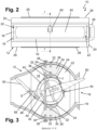
- Fig.2 shows a front view of the air outlet 10 of the first embodiment with an upwardly angled control element 60.
- Fig.3 shows a sectional view of the representation of Fig.2 along the line FF.
- the air guide element 40 is rotatably mounted between two webs 24.
- the webs 24 extend over the entire width of the air outlet 10 and have essentially the same length as the air guide element 40.
- the air guide element 40 has an essentially circular cross-section. Only on the rear side is a connecting section 44 provided, on which a pin 46 is arranged.
- the pin 46 engages in a slot 58 of a deflection element 50.
- the deflection element 50 is mounted in the housing 12 so that it can pivot about a pivot axis 5. A displacement of the pin 46 therefore causes the deflection element 50 to pivot upwards and downwards from a neutral position. This makes it possible to deflect incoming air accordingly and to supply it to the two groups of slats.
- the air outlet 10 also has the slats 30, which are pivotably mounted in the housing walls 28 and the webs 24 via bearing pins 32. Furthermore, the slats 30 are connected to one another via a coupling axis 36, so that the two groups of slats 30 pivot together. The upper group of slats 30 and the lower group of slats 30 are coupled via corresponding coupling pins, which are connected to one another via coupling rods 26.
- the air guide element 40 has openings 42.
- the openings 42 serve to ensure that the coupling axis 36 is not blocked by the air guide element 40 when the slats 30 are pivoted.
- the webs 24 also have a guide 58 (see, for example, Fig.5 and 7 ) on.
- the control element 60 is mounted in the air guide element 40 so that it can pivot about a pivot axis T.
- the control element 60 is connected to a fork 62 which engages around the common coupling axis 36. Pivoting the control element 60 about the pivot axis T causes both groups of slats 30 to pivot due to the coupling by the coupling axis 36.
- the fork 62 and the operating element 60 can be connected to one another in such a way that a length compensation takes place when the air guide element 40 is pivoted about its axis of rotation D.
- the air outlet 10 has ramps 22, which are located in particular at the air inlet and the air outlet.
- the design of the ramps is, for example, made of Fig. 13 for an air vent 10 of the second embodiment.
- the slats 30 are not visible from the outside when looking at the air outlet direction 16. This is because the diameter of the air guide element 40 is larger or at least the same size as the height of the air outlet opening 16. In addition, only the control element 60 and the front of the air guide element 40 are visible. However, air is always supplied via the air guide element 40 via the deflection element 50, which is not visible from the outside. The air vent 10 therefore makes it possible to provide air deflection without moving components being in the viewer's field of vision. In addition, improved air deflection is achieved via the slats 30, since these are located at a front position of the air vent 10. In conventional air vents from the prior art, the slats are usually further downstream in the region of the air duct 14, for example at the level of the deflection element 50.
- the air deflection via the slats 30 is additionally supported by the ramps 22 and the bevels 18.
- the Fig.3 The opposite bevels 18 shown are aligned such that they run tangentially to the air guide element 40.
- Good air deflection via the slats 30 is achieved in particular because the air guide element 40 is arranged concentrically to the housing walls 28 and has a substantially equal distance from the housing walls 28. If the distance between the air guide element 40 and the housing walls 28 were to decrease, particularly in the air outlet area, this would lead to an acceleration of the escaping air, which, however, counteracts the air deflection.
- Fig.4 shows a front view of the air outlet 10 of the first embodiment in a neutral position and Fig.5 shows a sectional view of the representation of Fig.4 along line BB.
- a housing box 28 is also arranged on the housing 12, in which a damping device is provided.
- the air guide element 40 is rotatably mounted in the housing via the side walls 20 via a bearing pin 78 and a bearing shaft 80.
- the bearing shaft 80 protrudes from the side wall 20 and is connected to a gear 66.
- the gear 66 is in engagement with a gear 68, which is coupled to a damper 70.
- a defined torque for pivoting the air guide element 40 is provided via the damper 70.
- the deflection element 50 is mounted via bearing pins 76 in the opposite housing walls 20.
- Fig.5 additionally shows the ramps 22, which guide the incoming air to the slats 30.
- the ramps 22 briefly accelerate the incoming air in the air inlet and air outlet areas.
- Fig.6 shows a front view of the air outlet 10 of the first embodiment with pivoted slats 30 and Fig.7 shows a sectional view of the representation of Fig.6 along the line DD.
- the pivoting of the groups of slats 30 is carried out via the control element 60, which connects the two groups to one another via the coupling axis 36.
- the individual slats 30 of the respective groups are connected to one another via their coupling pins 34 and the coupling rods 26.
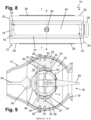
- Fig.8 shows a front view of an air outlet 10 of a second embodiment in a neutral position and Fig.9 shows a sectional view of the representation of Fig.8 along the line EE.
- the second embodiment differs from the first embodiment in that instead of a pin 46 which engages in a guide 58, the air guide element 40 has a gear section 56 on its rear side which engages with a corresponding gear section 54 of the deflection element 50.
- Fig.10 shows a front view of the air outlet 10 of the second embodiment with an upwardly pivoted control element 60 and Fig. 11 shows a sectional view of the representation of Fig.10 along line AA.
- the deflection element 50 When the air guide element 40 is pivoted upwards, the deflection element 50 is also pivoted upwards.
- the advantage over a rigid design of a deflection element 50 is that the air outlet 10 can be controlled intuitively. This is particularly useful when the air outlet 10 is controlled manually via the control element 60.
- the deflection element 50 can also be firmly connected to the air guide element 40.
- Fig. 12 shows a front view of the air outlet 10 of the second embodiment with pivoted slats 30 and Fig. 13 shows a sectional view of the representation of Fig. 12 along line CC.
- the ramps 22 are in particular arranged and constructed in such a way that they have essentially the same deflection surface as the slats 30 in a maximum pivoted position.
- Fig. 14 shows a different orientation, but the ramps 22 do not necessarily have to have the same orientation as the slats 30 in their maximum pivoted positions.
- the ramps 22 advantageously support the air deflection, since the air flowing through is accelerated in the area of the slats 30. This results in better air deflection than with air outlets with a lower speed. However, so that the air does not exit at too great an acceleration, the ramps 22 are designed in such a way that they widen the air channel again after the air has passed the area with the slats 30.
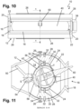
- Fig. 14 shows a front view of an air outlet 10 of a third embodiment in a neutral position and Fig. 15 shows a sectional view of the representation of Fig. 14 along line AA.
- the air outlet 10 does not have an operating element 60.
- the pivoting of the air guide element 40 is carried out by a motor, whereby a pinion can be provided in the housing box 38, for example, which is coupled to a gear wheel of the bearing shaft 80 and to an electric motor.
- the pivoting of the slats 30 can also be carried out by an electric motor or via another adjustment element.
- the air guide element 40 has a deflection element 50 that is rigidly attached to the connecting section 44. Since the air outlet 10 does not have an operating element 60 and is therefore not intuitively controlled by a user, the rigid design or connection of the deflection element 50 to the air guide element 40 is also advantageously possible without affecting the control. If, for example, air is to be deflected downwards, the air guide element 40 is rotated about its axis of rotation D so that the deflection element 50 is moved counterclockwise.
- Fig. 16 shows a front view of an air vent 10 of a fourth embodiment, which does not belong to the present invention, in a neutral position and Fig. 17 shows a sectional view of the representation of Fig. 16 along line AA.
- This air vent also does not have a control element 60.
- the air guide element 40 is not mounted between two webs 24, but on a bearing shaft 72.
- the bearing shaft 72 like the air guide element 40, has openings 74 which are intended to prevent the coupling axis 36 from blocking when the slats 30 are pivoted.
- the slats 30 are only pivotably mounted on the opposite housing walls 28 via bearing pins 32.
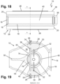
- Fig. 18 shows a front view of an air vent 10 of a fifth embodiment, which does not belong to the present invention, in a neutral position and Fig. 19 shows a sectional view of the representation of Fig. 18 along line AA.
- the fifth embodiment shown differs from the fourth embodiment in that the slats 30 are mounted on the bearing shaft 72 via bearing pins 32 in a merely pivotable manner.
- the bearing shaft 72 has corresponding receptacles for the bearing pins 32.
- the openings 42 of the air guide element 40 must then be selected such that even if the air guide element 40 is rotated about its axis of rotation D, no blocking by the bearing pins 32 occurs.
- the bearing pins 32 can also be formed directly onto the slats 30.
- the individual components of the Fig. 1 - 19 The various embodiments of air outlets 10 shown can be designed in several parts. This applies in particular to the Housing 12, the air guide element 40 and the control element 60.
- the air vents 10 shown in the figures have an attractive appearance, with no moving components visible above the air outlet openings 16. Only the control element 60 is visible in some versions.
- the arrangement of the slats 30 in the front section of the air vent 10 enables very good lateral air deflection, which could often not be achieved with so-called joint vents.
- the ramps 22 and the bevels 18 support the air deflection.
- the concentric arrangement of the air guide element 40 also ensures good deflection of the outflowing air. It is also important, however, that the lateral deflection via the slats 30 takes place after the deflection via the air guide element 40.
- the reference to lateral deflection and deflection orthogonal to this is not to be understood as restrictive.
- an air vent 10 shown in the figures can be arranged and installed rotated by 90 degrees, with the lateral deflection then being achieved by the air guide element 40 and the deflection upwards and downwards via the slats 30.
- All components of the air vents 10 can be manufactured, for example, in an injection molding process and made of plastic.
- the plastic used can have other additives so that the desired material properties are achieved. Furthermore, various plastics can be used.
Landscapes
- Engineering & Computer Science (AREA)
- Mechanical Engineering (AREA)
- Physics & Mathematics (AREA)
- Thermal Sciences (AREA)
- Chemical & Material Sciences (AREA)
- Combustion & Propulsion (AREA)
- General Engineering & Computer Science (AREA)
- Air-Flow Control Members (AREA)
Claims (9)
- Dispositif d'écoulement d'air (10) avec un dispositif de déflexion et un élément de guidage d'air (40), où le dispositif de déflexion comprend au moins deux groupes de lamelles (30) opposées, dans lequel un premier groupe de lamelles (30) étant disposé entre l'élément de guidage d'air (40) et une première paroi de boîtier (28) du dispositif d'écoulement d'air (10) opposée à l'élément de guidage d'air (40) et un deuxième groupe de lamelles (30) étant disposé entre l'élément de guidage d'air (40) et une deuxième paroi de boîtier (28) du dispositif d'écoulement d'air (10) opposée à l'élément de guidage d'air (40)sont disposés de manière à pouvoir pivoter et l'élément de guidage d'air (40) présente un élément de déviation (50) dépassant vers l'arrière dans le canal d'air (14), caractérisé en ce que l'élément de guidage d'air (40) est placé essentiellement au milieu entre deux entretoises (24) dans le conduit d'air (14), où une ouverture de sortie d'air (16) du dispositif d'écoulement d'air (10) présente une hauteur inférieure à celle de l'élément de guidage d'air (40) et où les au moins deux groupes de lamelles (30) opposées sont disposés de manière à pouvoir pivoter au-dessus des entretoises (24).
- Dispositif d'écoulement d'air (10) selon la revendication 1, caractérisé en ce que l'élément de guidage d'air (40) est disposé de manière à pouvoir tourner sur un arbre de palier (72).
- Dispositif d'écoulement d'air (10) selon l'une des revendications 1 à 2, caractérisé en ce que l'élément de déflexion (50) est relié de manière rigide ou pivotante à l'élément de guidage d'air (40).18 160 370.5
- Dispositif d'écoulement d'air (10) selon l'une des revendications 1 à 3, caractérisé en ce que les groupes de lamelles (30) opposés sont couplés entre eux par un axe commun.
- Dispositif d'écoulement d'air (10) selon la revendication 4, caractérisé en ce que l'axe commun (36) est relié à une fourche (62) d'un élément de commande (60) ou à un élément de réglage disposé à l'extérieur du conduit d'air (14) pour le pivotement des lamelles (30).
- Dispositif d'écoulement d'air (10) selon les revendications 1 à 5, caractérisé en ce que l'ouverture de sortie d'air (16) du dispositif d'écoulement d'air (10) dans la zone de sortie d'air présente un chanfrein (18).
- Dispositif d'écoulement d'air (10) selon les revendications 1 à 6, caractérisé en ce que le dispositif d'écoulement d'air (10) présente plusieurs groupes de lamelles (30), les lamelles (30) étant disposées de manière circonférentielle.
- Dispositif d'écoulement d'air (10) selon l'une des revendications 1 à 7, caractérisé en ce que le dispositif d'écoulement d'air (10) présente au moins une paire de rampes (22) qui sont situées sur des parois latérales opposées (20) dans le conduit d'air (14).
- Dispositif d'écoulement d'air (10) selon les revendications 1 à 8, caractérisé en ce que au moins les parois de boîtier opposées (28) sont disposées de manière concentrique par rapport à l'élément de guidage d'air (40) et la distance entre cet élément de guidage d'air (40) et les parois de boîtier opposées (28) est pour l'essentiel égale.
Applications Claiming Priority (1)
| Application Number | Priority Date | Filing Date | Title |
|---|---|---|---|
| DE102017106275.0A DE102017106275A1 (de) | 2017-03-23 | 2017-03-23 | Luftausströmer |
Publications (2)
| Publication Number | Publication Date |
|---|---|
| EP3378686A1 EP3378686A1 (fr) | 2018-09-26 |
| EP3378686B1 true EP3378686B1 (fr) | 2024-04-10 |
Family
ID=61581074
Family Applications (1)
| Application Number | Title | Priority Date | Filing Date |
|---|---|---|---|
| EP18160370.5A Active EP3378686B1 (fr) | 2017-03-23 | 2018-03-07 | Dispositif d'écoulement d'air |
Country Status (2)
| Country | Link |
|---|---|
| EP (1) | EP3378686B1 (fr) |
| DE (1) | DE102017106275A1 (fr) |
Families Citing this family (10)
| Publication number | Priority date | Publication date | Assignee | Title |
|---|---|---|---|---|
| DE102018004264A1 (de) * | 2018-05-28 | 2019-11-28 | Faurecia Intérieur Industrie | Auslassvorrichtung |
| EP3590744B1 (fr) * | 2018-07-06 | 2021-01-20 | Volvo Car Corporation | Diffuseur d'air réglable |
| DE102018130048A1 (de) * | 2018-11-28 | 2020-05-28 | Fischer Automotive Systems Gmbh & Co. Kg | Luftausströmer |
| CN110281740B (zh) * | 2019-01-07 | 2024-08-27 | 南京塔塔汽车零部件系统有限公司 | 一种出风口机构 |
| DE102019210048A1 (de) * | 2019-07-08 | 2021-01-14 | Faurecia Interieur Industrie | Luftausströmer |
| DE102019124175A1 (de) * | 2019-09-10 | 2021-03-11 | Bayerische Motoren Werke Aktiengesellschaft | Kraftfahrzeug-Luftausströmer mit einer Handhabe |
| DE102019006529A1 (de) * | 2019-09-16 | 2021-03-18 | Daimler Ag | Luftdüse und Belüftungs- und Klimatisierungsvorrichtung |
| US11007844B1 (en) * | 2019-11-14 | 2021-05-18 | JoysonQuin Automotive Systems North America, LLC | Multi-channel air vent assembly with narrow profile |
| DE102021201153A1 (de) | 2021-02-08 | 2022-08-11 | Volkswagen Aktiengesellschaft | Luftausströmer zum Einwirken auf einen ausströmenden Luftstrom |
| DE102022130819A1 (de) * | 2022-11-22 | 2024-05-23 | Fischer Automotive Systems Gmbh & Co. Kg | Lüftungsdüse |
Family Cites Families (6)
| Publication number | Priority date | Publication date | Assignee | Title |
|---|---|---|---|---|
| DE10202926A1 (de) * | 2002-01-25 | 2003-07-31 | Opel Adam Ag | Luftdüse |
| FR2886382B1 (fr) | 2005-05-26 | 2007-07-20 | Faurecia Interieur Ind Snc | Aerateur a reglage d'orientation et de debit a obturateur pivotant |
| DE202013012285U1 (de) | 2013-05-29 | 2016-01-18 | Faurecia Innenraum Systeme Gmbh | Luftausströmer |
| DE102013210053B3 (de) | 2013-05-29 | 2014-09-11 | Faurecia Innenraum Systeme Gmbh | Luftausströmer |
| JP6682236B2 (ja) * | 2015-04-28 | 2020-04-15 | 豊和化成株式会社 | 空気吹出装置及び当該空気吹出装置の集合体 |
| DE102015017009B4 (de) | 2015-12-30 | 2018-04-26 | Faurecia Innenraum Systeme Gmbh | Auslassvorrichtung |
-
2017
- 2017-03-23 DE DE102017106275.0A patent/DE102017106275A1/de not_active Ceased
-
2018
- 2018-03-07 EP EP18160370.5A patent/EP3378686B1/fr active Active
Also Published As
| Publication number | Publication date |
|---|---|
| DE102017106275A1 (de) | 2018-09-27 |
| EP3378686A1 (fr) | 2018-09-26 |
Similar Documents
| Publication | Publication Date | Title |
|---|---|---|
| EP3378686B1 (fr) | Dispositif d'écoulement d'air | |
| EP3403859B1 (fr) | Dispositif d'écoulement d'air | |
| EP2993068B1 (fr) | Dispositif d'ecoulement d'air ayant des elements de guidage d'air formes en plusieurs parties | |
| EP3294579B1 (fr) | Dispositif de régulation d'un flux d'air | |
| EP3405357B1 (fr) | Aérateur d'air avec contrôle de direction du flux d'air | |
| DE19943822B4 (de) | Strömungsleitanordnung, insbesondere Ausströmgrill für Lüftungs- und Klimaanlagen von Kraftfahrzeugen | |
| EP3192684B1 (fr) | Dispositif de déplacement de lamelles d'un diffuseur d'air | |
| EP3027443B1 (fr) | Élément de guidage d'air | |
| EP3530506B1 (fr) | Dispositif d'écoulement d'air | |
| EP3063026A1 (fr) | Diffuseur d'air | |
| DE202017102616U1 (de) | Luftausströmer zur Verwendung in einem Fahrzeug | |
| DE102012015519A1 (de) | Luftleitvorrichtung für eine Luftausströmvorrichtung eines Fahrzeugs | |
| EP3321113B1 (fr) | Dispositif d'écoulement d'air | |
| EP2475537A1 (fr) | Buse d'air arquée | |
| DE102010014075B4 (de) | Belüftungsdüse für den Innenraum eines Kraftfahrzeugs | |
| DE102021111535A1 (de) | Luftausströmeranordnung | |
| DE102017128105B4 (de) | Luftausströmer | |
| DE102019132921A1 (de) | Luftausströmer mit Bedieneinrichtung | |
| DE102022103498A1 (de) | Luftausströmer für ein fahrzeug | |
| DE102016110933B3 (de) | Luftausströmer | |
| DE102022100478A1 (de) | Luftausströmer für ein fahrzeug sowie luftausströmersystem | |
| EP1663682B1 (fr) | Dispositif de coulement d'air, notamment pour un vehicule | |
| DE102021117250A1 (de) | Luftausströmer für ein fahrzeug | |
| EP2749439B1 (fr) | Buse d'évacuation d'air | |
| DE102021103235A1 (de) | Luftausströmer für ein fahrzeug sowie luftausströmersystem |
Legal Events
| Date | Code | Title | Description |
|---|---|---|---|
| PUAI | Public reference made under article 153(3) epc to a published international application that has entered the european phase |
Free format text: ORIGINAL CODE: 0009012 |
|
| STAA | Information on the status of an ep patent application or granted ep patent |
Free format text: STATUS: THE APPLICATION HAS BEEN PUBLISHED |
|
| AK | Designated contracting states |
Kind code of ref document: A1 Designated state(s): AL AT BE BG CH CY CZ DE DK EE ES FI FR GB GR HR HU IE IS IT LI LT LU LV MC MK MT NL NO PL PT RO RS SE SI SK SM TR |
|
| AX | Request for extension of the european patent |
Extension state: BA ME |
|
| STAA | Information on the status of an ep patent application or granted ep patent |
Free format text: STATUS: REQUEST FOR EXAMINATION WAS MADE |
|
| 17P | Request for examination filed |
Effective date: 20190128 |
|
| RBV | Designated contracting states (corrected) |
Designated state(s): AL AT BE BG CH CY CZ DE DK EE ES FI FR GB GR HR HU IE IS IT LI LT LU LV MC MK MT NL NO PL PT RO RS SE SI SK SM TR |
|
| STAA | Information on the status of an ep patent application or granted ep patent |
Free format text: STATUS: EXAMINATION IS IN PROGRESS |
|
| 17Q | First examination report despatched |
Effective date: 20210924 |
|
| GRAP | Despatch of communication of intention to grant a patent |
Free format text: ORIGINAL CODE: EPIDOSNIGR1 |
|
| STAA | Information on the status of an ep patent application or granted ep patent |
Free format text: STATUS: GRANT OF PATENT IS INTENDED |
|
| RIC1 | Information provided on ipc code assigned before grant |
Ipc: F24F 13/065 20060101ALI20221223BHEP Ipc: B60H 1/34 20060101AFI20221223BHEP |
|
| INTG | Intention to grant announced |
Effective date: 20230130 |
|
| 19U | Interruption of proceedings before grant |
Effective date: 20221101 |
|
| 19W | Proceedings resumed before grant after interruption of proceedings |
Effective date: 20231002 |
|
| GRAJ | Information related to disapproval of communication of intention to grant by the applicant or resumption of examination proceedings by the epo deleted |
Free format text: ORIGINAL CODE: EPIDOSDIGR1 |
|
| GRAP | Despatch of communication of intention to grant a patent |
Free format text: ORIGINAL CODE: EPIDOSNIGR1 |
|
| INTG | Intention to grant announced |
Effective date: 20231018 |
|
| GRAS | Grant fee paid |
Free format text: ORIGINAL CODE: EPIDOSNIGR3 |
|
| GRAA | (expected) grant |
Free format text: ORIGINAL CODE: 0009210 |
|
| STAA | Information on the status of an ep patent application or granted ep patent |
Free format text: STATUS: THE PATENT HAS BEEN GRANTED |
|
| AK | Designated contracting states |
Kind code of ref document: B1 Designated state(s): AL AT BE BG CH CY CZ DE DK EE ES FI FR GB GR HR HU IE IS IT LI LT LU LV MC MK MT NL NO PL PT RO RS SE SI SK SM TR |
|
| REG | Reference to a national code |
Ref country code: GB Ref legal event code: FG4D Free format text: NOT ENGLISH |
|
| REG | Reference to a national code |
Ref country code: CH Ref legal event code: EP |
|
| REG | Reference to a national code |
Ref country code: DE Ref legal event code: R096 Ref document number: 502018014403 Country of ref document: DE |
|
| REG | Reference to a national code |
Ref country code: IE Ref legal event code: FG4D Free format text: LANGUAGE OF EP DOCUMENT: GERMAN |
|
| REG | Reference to a national code |
Ref country code: LT Ref legal event code: MG9D |
|
| REG | Reference to a national code |
Ref country code: NL Ref legal event code: MP Effective date: 20240410 |
|
| PG25 | Lapsed in a contracting state [announced via postgrant information from national office to epo] |
Ref country code: NL Free format text: LAPSE BECAUSE OF FAILURE TO SUBMIT A TRANSLATION OF THE DESCRIPTION OR TO PAY THE FEE WITHIN THE PRESCRIBED TIME-LIMIT Effective date: 20240410 |
|
| PG25 | Lapsed in a contracting state [announced via postgrant information from national office to epo] |
Ref country code: NL Free format text: LAPSE BECAUSE OF FAILURE TO SUBMIT A TRANSLATION OF THE DESCRIPTION OR TO PAY THE FEE WITHIN THE PRESCRIBED TIME-LIMIT Effective date: 20240410 |
|
| PG25 | Lapsed in a contracting state [announced via postgrant information from national office to epo] |
Ref country code: IS Free format text: LAPSE BECAUSE OF FAILURE TO SUBMIT A TRANSLATION OF THE DESCRIPTION OR TO PAY THE FEE WITHIN THE PRESCRIBED TIME-LIMIT Effective date: 20240810 |
|
| PG25 | Lapsed in a contracting state [announced via postgrant information from national office to epo] |
Ref country code: BG Free format text: LAPSE BECAUSE OF FAILURE TO SUBMIT A TRANSLATION OF THE DESCRIPTION OR TO PAY THE FEE WITHIN THE PRESCRIBED TIME-LIMIT Effective date: 20240410 |
|
| PG25 | Lapsed in a contracting state [announced via postgrant information from national office to epo] |
Ref country code: HR Free format text: LAPSE BECAUSE OF FAILURE TO SUBMIT A TRANSLATION OF THE DESCRIPTION OR TO PAY THE FEE WITHIN THE PRESCRIBED TIME-LIMIT Effective date: 20240410 Ref country code: FI Free format text: LAPSE BECAUSE OF FAILURE TO SUBMIT A TRANSLATION OF THE DESCRIPTION OR TO PAY THE FEE WITHIN THE PRESCRIBED TIME-LIMIT Effective date: 20240410 |
|
| PG25 | Lapsed in a contracting state [announced via postgrant information from national office to epo] |
Ref country code: GR Free format text: LAPSE BECAUSE OF FAILURE TO SUBMIT A TRANSLATION OF THE DESCRIPTION OR TO PAY THE FEE WITHIN THE PRESCRIBED TIME-LIMIT Effective date: 20240711 |
|
| PG25 | Lapsed in a contracting state [announced via postgrant information from national office to epo] |
Ref country code: PT Free format text: LAPSE BECAUSE OF FAILURE TO SUBMIT A TRANSLATION OF THE DESCRIPTION OR TO PAY THE FEE WITHIN THE PRESCRIBED TIME-LIMIT Effective date: 20240812 |
|
| PG25 | Lapsed in a contracting state [announced via postgrant information from national office to epo] |
Ref country code: ES Free format text: LAPSE BECAUSE OF FAILURE TO SUBMIT A TRANSLATION OF THE DESCRIPTION OR TO PAY THE FEE WITHIN THE PRESCRIBED TIME-LIMIT Effective date: 20240410 |
|
| PG25 | Lapsed in a contracting state [announced via postgrant information from national office to epo] |
Ref country code: PL Free format text: LAPSE BECAUSE OF FAILURE TO SUBMIT A TRANSLATION OF THE DESCRIPTION OR TO PAY THE FEE WITHIN THE PRESCRIBED TIME-LIMIT Effective date: 20240410 |
|
| PG25 | Lapsed in a contracting state [announced via postgrant information from national office to epo] |
Ref country code: LV Free format text: LAPSE BECAUSE OF FAILURE TO SUBMIT A TRANSLATION OF THE DESCRIPTION OR TO PAY THE FEE WITHIN THE PRESCRIBED TIME-LIMIT Effective date: 20240410 |
|
| PG25 | Lapsed in a contracting state [announced via postgrant information from national office to epo] |
Ref country code: PT Free format text: LAPSE BECAUSE OF FAILURE TO SUBMIT A TRANSLATION OF THE DESCRIPTION OR TO PAY THE FEE WITHIN THE PRESCRIBED TIME-LIMIT Effective date: 20240812 Ref country code: PL Free format text: LAPSE BECAUSE OF FAILURE TO SUBMIT A TRANSLATION OF THE DESCRIPTION OR TO PAY THE FEE WITHIN THE PRESCRIBED TIME-LIMIT Effective date: 20240410 Ref country code: NO Free format text: LAPSE BECAUSE OF FAILURE TO SUBMIT A TRANSLATION OF THE DESCRIPTION OR TO PAY THE FEE WITHIN THE PRESCRIBED TIME-LIMIT Effective date: 20240710 Ref country code: LV Free format text: LAPSE BECAUSE OF FAILURE TO SUBMIT A TRANSLATION OF THE DESCRIPTION OR TO PAY THE FEE WITHIN THE PRESCRIBED TIME-LIMIT Effective date: 20240410 Ref country code: IS Free format text: LAPSE BECAUSE OF FAILURE TO SUBMIT A TRANSLATION OF THE DESCRIPTION OR TO PAY THE FEE WITHIN THE PRESCRIBED TIME-LIMIT Effective date: 20240810 Ref country code: HR Free format text: LAPSE BECAUSE OF FAILURE TO SUBMIT A TRANSLATION OF THE DESCRIPTION OR TO PAY THE FEE WITHIN THE PRESCRIBED TIME-LIMIT Effective date: 20240410 Ref country code: GR Free format text: LAPSE BECAUSE OF FAILURE TO SUBMIT A TRANSLATION OF THE DESCRIPTION OR TO PAY THE FEE WITHIN THE PRESCRIBED TIME-LIMIT Effective date: 20240711 Ref country code: FI Free format text: LAPSE BECAUSE OF FAILURE TO SUBMIT A TRANSLATION OF THE DESCRIPTION OR TO PAY THE FEE WITHIN THE PRESCRIBED TIME-LIMIT Effective date: 20240410 Ref country code: ES Free format text: LAPSE BECAUSE OF FAILURE TO SUBMIT A TRANSLATION OF THE DESCRIPTION OR TO PAY THE FEE WITHIN THE PRESCRIBED TIME-LIMIT Effective date: 20240410 Ref country code: BG Free format text: LAPSE BECAUSE OF FAILURE TO SUBMIT A TRANSLATION OF THE DESCRIPTION OR TO PAY THE FEE WITHIN THE PRESCRIBED TIME-LIMIT Effective date: 20240410 Ref country code: RS Free format text: LAPSE BECAUSE OF FAILURE TO SUBMIT A TRANSLATION OF THE DESCRIPTION OR TO PAY THE FEE WITHIN THE PRESCRIBED TIME-LIMIT Effective date: 20240710 |
|
| REG | Reference to a national code |
Ref country code: DE Ref legal event code: R097 Ref document number: 502018014403 Country of ref document: DE |
|
| PG25 | Lapsed in a contracting state [announced via postgrant information from national office to epo] |
Ref country code: DK Free format text: LAPSE BECAUSE OF FAILURE TO SUBMIT A TRANSLATION OF THE DESCRIPTION OR TO PAY THE FEE WITHIN THE PRESCRIBED TIME-LIMIT Effective date: 20240410 |
|
| PG25 | Lapsed in a contracting state [announced via postgrant information from national office to epo] |
Ref country code: EE Free format text: LAPSE BECAUSE OF FAILURE TO SUBMIT A TRANSLATION OF THE DESCRIPTION OR TO PAY THE FEE WITHIN THE PRESCRIBED TIME-LIMIT Effective date: 20240410 |
|
| PG25 | Lapsed in a contracting state [announced via postgrant information from national office to epo] |
Ref country code: CZ Free format text: LAPSE BECAUSE OF FAILURE TO SUBMIT A TRANSLATION OF THE DESCRIPTION OR TO PAY THE FEE WITHIN THE PRESCRIBED TIME-LIMIT Effective date: 20240410 |
|
| PG25 | Lapsed in a contracting state [announced via postgrant information from national office to epo] |
Ref country code: RO Free format text: LAPSE BECAUSE OF FAILURE TO SUBMIT A TRANSLATION OF THE DESCRIPTION OR TO PAY THE FEE WITHIN THE PRESCRIBED TIME-LIMIT Effective date: 20240410 Ref country code: SK Free format text: LAPSE BECAUSE OF FAILURE TO SUBMIT A TRANSLATION OF THE DESCRIPTION OR TO PAY THE FEE WITHIN THE PRESCRIBED TIME-LIMIT Effective date: 20240410 |
|
| PG25 | Lapsed in a contracting state [announced via postgrant information from national office to epo] |
Ref country code: SM Free format text: LAPSE BECAUSE OF FAILURE TO SUBMIT A TRANSLATION OF THE DESCRIPTION OR TO PAY THE FEE WITHIN THE PRESCRIBED TIME-LIMIT Effective date: 20240410 |
|
| PG25 | Lapsed in a contracting state [announced via postgrant information from national office to epo] |
Ref country code: SM Free format text: LAPSE BECAUSE OF FAILURE TO SUBMIT A TRANSLATION OF THE DESCRIPTION OR TO PAY THE FEE WITHIN THE PRESCRIBED TIME-LIMIT Effective date: 20240410 Ref country code: SK Free format text: LAPSE BECAUSE OF FAILURE TO SUBMIT A TRANSLATION OF THE DESCRIPTION OR TO PAY THE FEE WITHIN THE PRESCRIBED TIME-LIMIT Effective date: 20240410 Ref country code: RO Free format text: LAPSE BECAUSE OF FAILURE TO SUBMIT A TRANSLATION OF THE DESCRIPTION OR TO PAY THE FEE WITHIN THE PRESCRIBED TIME-LIMIT Effective date: 20240410 Ref country code: EE Free format text: LAPSE BECAUSE OF FAILURE TO SUBMIT A TRANSLATION OF THE DESCRIPTION OR TO PAY THE FEE WITHIN THE PRESCRIBED TIME-LIMIT Effective date: 20240410 Ref country code: DK Free format text: LAPSE BECAUSE OF FAILURE TO SUBMIT A TRANSLATION OF THE DESCRIPTION OR TO PAY THE FEE WITHIN THE PRESCRIBED TIME-LIMIT Effective date: 20240410 Ref country code: CZ Free format text: LAPSE BECAUSE OF FAILURE TO SUBMIT A TRANSLATION OF THE DESCRIPTION OR TO PAY THE FEE WITHIN THE PRESCRIBED TIME-LIMIT Effective date: 20240410 |
|
| PG25 | Lapsed in a contracting state [announced via postgrant information from national office to epo] |
Ref country code: IT Free format text: LAPSE BECAUSE OF FAILURE TO SUBMIT A TRANSLATION OF THE DESCRIPTION OR TO PAY THE FEE WITHIN THE PRESCRIBED TIME-LIMIT Effective date: 20240410 |
|
| PLBE | No opposition filed within time limit |
Free format text: ORIGINAL CODE: 0009261 |
|
| STAA | Information on the status of an ep patent application or granted ep patent |
Free format text: STATUS: NO OPPOSITION FILED WITHIN TIME LIMIT |
|
| 26N | No opposition filed |
Effective date: 20250113 |
|
| PG25 | Lapsed in a contracting state [announced via postgrant information from national office to epo] |
Ref country code: SI Free format text: LAPSE BECAUSE OF FAILURE TO SUBMIT A TRANSLATION OF THE DESCRIPTION OR TO PAY THE FEE WITHIN THE PRESCRIBED TIME-LIMIT Effective date: 20240410 |
|
| REG | Reference to a national code |
Ref country code: DE Ref legal event code: R081 Ref document number: 502018014403 Country of ref document: DE Owner name: MOTHERSON DRSC DEUTSCHLAND GMBH, DE Free format text: FORMER OWNER: DR. SCHNEIDER KUNSTSTOFFWERKE GMBH, 96317 KRONACH, DE |
|
| REG | Reference to a national code |
Ref country code: GB Ref legal event code: 732E Free format text: REGISTERED BETWEEN 20250724 AND 20250730 |
|
| PG25 | Lapsed in a contracting state [announced via postgrant information from national office to epo] |
Ref country code: SE Free format text: LAPSE BECAUSE OF FAILURE TO SUBMIT A TRANSLATION OF THE DESCRIPTION OR TO PAY THE FEE WITHIN THE PRESCRIBED TIME-LIMIT Effective date: 20240410 |
|
| PG25 | Lapsed in a contracting state [announced via postgrant information from national office to epo] |
Ref country code: MC Free format text: LAPSE BECAUSE OF FAILURE TO SUBMIT A TRANSLATION OF THE DESCRIPTION OR TO PAY THE FEE WITHIN THE PRESCRIBED TIME-LIMIT Effective date: 20240410 |
|
| REG | Reference to a national code |
Ref country code: CH Ref legal event code: H13 Free format text: ST27 STATUS EVENT CODE: U-0-0-H10-H13 (AS PROVIDED BY THE NATIONAL OFFICE) Effective date: 20251024 |
|
| PG25 | Lapsed in a contracting state [announced via postgrant information from national office to epo] |
Ref country code: LU Free format text: LAPSE BECAUSE OF NON-PAYMENT OF DUE FEES Effective date: 20250307 |
|
| REG | Reference to a national code |
Ref country code: BE Ref legal event code: MM Effective date: 20250331 |
|
| PG25 | Lapsed in a contracting state [announced via postgrant information from national office to epo] |
Ref country code: BE Free format text: LAPSE BECAUSE OF NON-PAYMENT OF DUE FEES Effective date: 20250331 |
|
| PG25 | Lapsed in a contracting state [announced via postgrant information from national office to epo] |
Ref country code: CH Free format text: LAPSE BECAUSE OF NON-PAYMENT OF DUE FEES Effective date: 20250331 |
|
| PG25 | Lapsed in a contracting state [announced via postgrant information from national office to epo] |
Ref country code: IE Free format text: LAPSE BECAUSE OF NON-PAYMENT OF DUE FEES Effective date: 20250307 |
|
| PGFP | Annual fee paid to national office [announced via postgrant information from national office to epo] |
Ref country code: GB Payment date: 20260324 Year of fee payment: 9 |
|
| PGFP | Annual fee paid to national office [announced via postgrant information from national office to epo] |
Ref country code: DE Payment date: 20260320 Year of fee payment: 9 |
|
| PGFP | Annual fee paid to national office [announced via postgrant information from national office to epo] |
Ref country code: FR Payment date: 20260324 Year of fee payment: 9 |