EP3378968B1 - Elektrolysevorrichtung für kohlendioxid und elektrolyseverfahren für kohlendioxid - Google Patents
Elektrolysevorrichtung für kohlendioxid und elektrolyseverfahren für kohlendioxid Download PDFInfo
- Publication number
- EP3378968B1 EP3378968B1 EP17191058.1A EP17191058A EP3378968B1 EP 3378968 B1 EP3378968 B1 EP 3378968B1 EP 17191058 A EP17191058 A EP 17191058A EP 3378968 B1 EP3378968 B1 EP 3378968B1
- Authority
- EP
- European Patent Office
- Prior art keywords
- cathode
- anode
- solution
- flow path
- carbon dioxide
- Prior art date
- Legal status (The legal status is an assumption and is not a legal conclusion. Google has not performed a legal analysis and makes no representation as to the accuracy of the status listed.)
- Active
Links
Images



Classifications
-
- C—CHEMISTRY; METALLURGY
- C25—ELECTROLYTIC OR ELECTROPHORETIC PROCESSES; APPARATUS THEREFOR
- C25B—ELECTROLYTIC OR ELECTROPHORETIC PROCESSES FOR THE PRODUCTION OF COMPOUNDS OR NON-METALS; APPARATUS THEREFOR
- C25B1/00—Electrolytic production of inorganic compounds or non-metals
- C25B1/01—Products
- C25B1/02—Hydrogen or oxygen
- C25B1/04—Hydrogen or oxygen by electrolysis of water
-
- C—CHEMISTRY; METALLURGY
- C25—ELECTROLYTIC OR ELECTROPHORETIC PROCESSES; APPARATUS THEREFOR
- C25B—ELECTROLYTIC OR ELECTROPHORETIC PROCESSES FOR THE PRODUCTION OF COMPOUNDS OR NON-METALS; APPARATUS THEREFOR
- C25B1/00—Electrolytic production of inorganic compounds or non-metals
-
- C—CHEMISTRY; METALLURGY
- C25—ELECTROLYTIC OR ELECTROPHORETIC PROCESSES; APPARATUS THEREFOR
- C25B—ELECTROLYTIC OR ELECTROPHORETIC PROCESSES FOR THE PRODUCTION OF COMPOUNDS OR NON-METALS; APPARATUS THEREFOR
- C25B1/00—Electrolytic production of inorganic compounds or non-metals
- C25B1/01—Products
- C25B1/23—Carbon monoxide or syngas
-
- C—CHEMISTRY; METALLURGY
- C25—ELECTROLYTIC OR ELECTROPHORETIC PROCESSES; APPARATUS THEREFOR
- C25B—ELECTROLYTIC OR ELECTROPHORETIC PROCESSES FOR THE PRODUCTION OF COMPOUNDS OR NON-METALS; APPARATUS THEREFOR
- C25B15/00—Operating or servicing cells
- C25B15/02—Process control or regulation
-
- C—CHEMISTRY; METALLURGY
- C25—ELECTROLYTIC OR ELECTROPHORETIC PROCESSES; APPARATUS THEREFOR
- C25B—ELECTROLYTIC OR ELECTROPHORETIC PROCESSES FOR THE PRODUCTION OF COMPOUNDS OR NON-METALS; APPARATUS THEREFOR
- C25B15/00—Operating or servicing cells
- C25B15/02—Process control or regulation
- C25B15/023—Measuring, analysing or testing during electrolytic production
-
- C—CHEMISTRY; METALLURGY
- C25—ELECTROLYTIC OR ELECTROPHORETIC PROCESSES; APPARATUS THEREFOR
- C25B—ELECTROLYTIC OR ELECTROPHORETIC PROCESSES FOR THE PRODUCTION OF COMPOUNDS OR NON-METALS; APPARATUS THEREFOR
- C25B15/00—Operating or servicing cells
- C25B15/08—Supplying or removing reactants or electrolytes; Regeneration of electrolytes
-
- C—CHEMISTRY; METALLURGY
- C25—ELECTROLYTIC OR ELECTROPHORETIC PROCESSES; APPARATUS THEREFOR
- C25B—ELECTROLYTIC OR ELECTROPHORETIC PROCESSES FOR THE PRODUCTION OF COMPOUNDS OR NON-METALS; APPARATUS THEREFOR
- C25B15/00—Operating or servicing cells
- C25B15/08—Supplying or removing reactants or electrolytes; Regeneration of electrolytes
- C25B15/087—Recycling of electrolyte to electrochemical cell
-
- C—CHEMISTRY; METALLURGY
- C25—ELECTROLYTIC OR ELECTROPHORETIC PROCESSES; APPARATUS THEREFOR
- C25B—ELECTROLYTIC OR ELECTROPHORETIC PROCESSES FOR THE PRODUCTION OF COMPOUNDS OR NON-METALS; APPARATUS THEREFOR
- C25B3/00—Electrolytic production of organic compounds
- C25B3/01—Products
- C25B3/03—Acyclic or carbocyclic hydrocarbons
-
- C—CHEMISTRY; METALLURGY
- C25—ELECTROLYTIC OR ELECTROPHORETIC PROCESSES; APPARATUS THEREFOR
- C25B—ELECTROLYTIC OR ELECTROPHORETIC PROCESSES FOR THE PRODUCTION OF COMPOUNDS OR NON-METALS; APPARATUS THEREFOR
- C25B3/00—Electrolytic production of organic compounds
- C25B3/01—Products
- C25B3/07—Oxygen containing compounds
-
- C—CHEMISTRY; METALLURGY
- C25—ELECTROLYTIC OR ELECTROPHORETIC PROCESSES; APPARATUS THEREFOR
- C25B—ELECTROLYTIC OR ELECTROPHORETIC PROCESSES FOR THE PRODUCTION OF COMPOUNDS OR NON-METALS; APPARATUS THEREFOR
- C25B3/00—Electrolytic production of organic compounds
- C25B3/20—Processes
- C25B3/25—Reduction
-
- C—CHEMISTRY; METALLURGY
- C25—ELECTROLYTIC OR ELECTROPHORETIC PROCESSES; APPARATUS THEREFOR
- C25B—ELECTROLYTIC OR ELECTROPHORETIC PROCESSES FOR THE PRODUCTION OF COMPOUNDS OR NON-METALS; APPARATUS THEREFOR
- C25B3/00—Electrolytic production of organic compounds
- C25B3/20—Processes
- C25B3/25—Reduction
- C25B3/26—Reduction of carbon dioxide
-
- C—CHEMISTRY; METALLURGY
- C25—ELECTROLYTIC OR ELECTROPHORETIC PROCESSES; APPARATUS THEREFOR
- C25B—ELECTROLYTIC OR ELECTROPHORETIC PROCESSES FOR THE PRODUCTION OF COMPOUNDS OR NON-METALS; APPARATUS THEREFOR
- C25B9/00—Cells or assemblies of cells; Constructional parts of cells; Assemblies of constructional parts, e.g. electrode-diaphragm assemblies; Process-related cell features
- C25B9/17—Cells comprising dimensionally-stable non-movable electrodes; Assemblies of constructional parts thereof
-
- C—CHEMISTRY; METALLURGY
- C25—ELECTROLYTIC OR ELECTROPHORETIC PROCESSES; APPARATUS THEREFOR
- C25B—ELECTROLYTIC OR ELECTROPHORETIC PROCESSES FOR THE PRODUCTION OF COMPOUNDS OR NON-METALS; APPARATUS THEREFOR
- C25B9/00—Cells or assemblies of cells; Constructional parts of cells; Assemblies of constructional parts, e.g. electrode-diaphragm assemblies; Process-related cell features
- C25B9/17—Cells comprising dimensionally-stable non-movable electrodes; Assemblies of constructional parts thereof
- C25B9/19—Cells comprising dimensionally-stable non-movable electrodes; Assemblies of constructional parts thereof with diaphragms
-
- C—CHEMISTRY; METALLURGY
- C25—ELECTROLYTIC OR ELECTROPHORETIC PROCESSES; APPARATUS THEREFOR
- C25B—ELECTROLYTIC OR ELECTROPHORETIC PROCESSES FOR THE PRODUCTION OF COMPOUNDS OR NON-METALS; APPARATUS THEREFOR
- C25B9/00—Cells or assemblies of cells; Constructional parts of cells; Assemblies of constructional parts, e.g. electrode-diaphragm assemblies; Process-related cell features
- C25B9/17—Cells comprising dimensionally-stable non-movable electrodes; Assemblies of constructional parts thereof
- C25B9/19—Cells comprising dimensionally-stable non-movable electrodes; Assemblies of constructional parts thereof with diaphragms
- C25B9/23—Cells comprising dimensionally-stable non-movable electrodes; Assemblies of constructional parts thereof with diaphragms comprising ion-exchange membranes in or on which electrode material is embedded
-
- C—CHEMISTRY; METALLURGY
- C25—ELECTROLYTIC OR ELECTROPHORETIC PROCESSES; APPARATUS THEREFOR
- C25B—ELECTROLYTIC OR ELECTROPHORETIC PROCESSES FOR THE PRODUCTION OF COMPOUNDS OR NON-METALS; APPARATUS THEREFOR
- C25B9/00—Cells or assemblies of cells; Constructional parts of cells; Assemblies of constructional parts, e.g. electrode-diaphragm assemblies; Process-related cell features
- C25B9/60—Constructional parts of cells
- C25B9/65—Means for supplying current; Electrode connections; Electric inter-cell connections
-
- C—CHEMISTRY; METALLURGY
- C25—ELECTROLYTIC OR ELECTROPHORETIC PROCESSES; APPARATUS THEREFOR
- C25B—ELECTROLYTIC OR ELECTROPHORETIC PROCESSES FOR THE PRODUCTION OF COMPOUNDS OR NON-METALS; APPARATUS THEREFOR
- C25B9/00—Cells or assemblies of cells; Constructional parts of cells; Assemblies of constructional parts, e.g. electrode-diaphragm assemblies; Process-related cell features
- C25B9/70—Assemblies comprising two or more cells
- C25B9/73—Assemblies comprising two or more cells of the filter-press type
-
- Y—GENERAL TAGGING OF NEW TECHNOLOGICAL DEVELOPMENTS; GENERAL TAGGING OF CROSS-SECTIONAL TECHNOLOGIES SPANNING OVER SEVERAL SECTIONS OF THE IPC; TECHNICAL SUBJECTS COVERED BY FORMER USPC CROSS-REFERENCE ART COLLECTIONS [XRACs] AND DIGESTS
- Y02—TECHNOLOGIES OR APPLICATIONS FOR MITIGATION OR ADAPTATION AGAINST CLIMATE CHANGE
- Y02E—REDUCTION OF GREENHOUSE GAS [GHG] EMISSIONS, RELATED TO ENERGY GENERATION, TRANSMISSION OR DISTRIBUTION
- Y02E60/00—Enabling technologies; Technologies with a potential or indirect contribution to GHG emissions mitigation
- Y02E60/30—Hydrogen technology
- Y02E60/36—Hydrogen production from non-carbon containing sources, e.g. by water electrolysis
Definitions
- Arrangements described herein generally relate to a carbon dioxide electrolytic device and a carbon dioxide electrolytic method.
- a carbon dioxide electrolytic device for example, a structure in which a cathode solution and CO 2 gas are brought in contact with a cathode and an anode solution is brought in contact with an anode is being studied.
- a specific configuration of the electrolytic device for example, there can be cited a configuration which includes a cathode solution flow path disposed along one surface of the cathode, a CO 2 gas flow path disposed along the other surface of the cathode, an anode solution flow path disposed along one surface of an anode, and a separator disposed between the cathode solution flow path and the anode solution flow path.
- WO 2016/134952 A1 relates to: a method for producing an electrode, in which a layer comprising a catalyst containing Cu + /Cu is deposited onto a non-copper substrate; an electrode comprising a non-copper substrate; a coating comprising a catalyst that contains Cu + /Cu; and an electrolysis cell comprising the claimed electrode.
- WO 2017/025285 A1 relates to a gas diffusion electrode comprising a, preferably copper-containing, carrier and a first layer having at least copper and at least one binder, wherein the first layer has hydrophilic and hydrophobic pores and/or channels, further comprising a second layer having copper and at least one binder, wherein the second layer is located on the carrier and the first layer is located on the second layer, wherein the binder content in the first layer is less than in the second layer. It further relates to a method for producing a gas diffusion electrode of this type and an electrolysis cell comprising a gas diffusion electrode of this type.
- WO 2017/033131 A1 relates to an electrochemical activation system that comprises a cell which is adapted to produce an electrochemically activated solution, such as an anolyte or a catholyte solution, by means of an electrolysis process.
- the electrochemical activation system further has a system which automatically cleans the cells. The system goes into flushing mode if the time elapses or the current limit goes below the set level.
- the electrochemical activation system further comprises a time to flush indicator along with a current indicator for the same.
- WO 2016/193738 A1 relates to an apparatus for manufacturing oxidant, the apparatus comprising an electrochemical reactor, a feed inlet for receiving feed materials and a product outlet for the oxidant; the electrochemical reactor being in fluid communication with the feed inlet and the product outlet and comprising one or more anodes and one or more cathodes.
- the apparatus further comprises means for detecting oxidant within the apparatus, and flow controlling means configured to control the flow of fluid through the product outlet and to communicate with the means for detecting oxidant.
- US 7 507 323 B1 relates to a water treatment system including a circulation pump and an electrolytic chamber in fluid communication with a main body of water. Electrolytic plates within the electrolytic chamber generate chlorine. When mineral deposits foul the electrolytic plates, water is isolated within the electrolytic chamber and a minimal amount of a pH-reducing agent is added to the electrolytic chamber to remove the mineral deposits.
- the pH-reducing agent is admitted on a periodic timed basis.
- the pH-reducing agent is added when the pH of the main body of water falls below a predetermined threshold.
- cleaning is accomplished by adding the pH-reducing agent when the circulation pump is not operating so that the acid dwells within the electrolytic chamber for a sufficient amount of time. Activation of the circulation pump causes the pH-reducing agent to enter the main body of water.
- US 4,185,142 A describes methods for rejuvenation of oxygen electrodes that are aimed at maximizing the power efficiency available from such oxygen electrodes while minimizing the voltage necessary to operate such oxygen electrodes over extended periods of time.
- the methods include in situ and out of cell techniques using hot water washing followed by air drying and dilute acid washing followed by air drying.
- a subject to be solved by the present invention is to provide a carbon dioxide electrolytic device which makes it possible to maintain a cell output for a long stretch of time and a carbon dioxide electrolytic method.
- an electrochemical reaction device and an electrochemical reaction method capable to maintaining a cell output for a long stretch of time and a carbon dioxide electrolytic method according to Claim 1 and other dependent claims hereof.
- a carbon dioxide electrolytic device that includes: an electrolysis cell including a cathode to reduce carbon dioxide and thus produce a carbon compound, an anode to oxidize water or hydroxide ions and thus produce oxygen, a carbon dioxide supply unit to supply carbon dioxide to the cathode, a solution supply unit to supply an electrolytic solution containing water to at least one of the cathode and the anode, and a separator to separate the anode and the cathode; a power supply connected to the anode and the cathode; a reaction control unit to cause a reduction reaction of the carbon dioxide in the cathode and an oxidation reaction of the water or hydroxide ions in the anode by passing an electric current from the power supply to the anode and the cathode; a refresh material supply unit including a gas supply unit to supply a gaseous substance as a part of the refresh material to at least one of the anode and the cathode, and
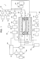
- Fig. 1 is a view illustrating a configuration of a carbon dioxide electrolytic device according to a first arrangement
- Fig. 2 is a sectional view illustrating a configuration of an electrolysis cell in the electrolytic device illustrated in Fig. 1 .
- an electrolysis cell 2 includes: an electrolysis cell 2; an anode solution supply system 100 which supplies an anode solution to the electrolysis cell 2; a cathode solution supply system 200 which supplies a cathode solution to the electrolysis cell 2; a gas supply system 300 which supplies carbon dioxide (CO 2 ) gas to the electrolysis cell 2; a product collection system 400 which collects a product produced by a reduction reaction in the electrolysis cell 2; a control system 500 which detects a type and a production amount of the collected product and, performs control of the product and control of a refresh operation; a waste solution collection system 600 which collects a waste solution of the cathode solution or the anode solution; and a refresh material supply unit 700 which recovers an anode, a cathode, or the like of the electrolysis cell 2.
- the electrolysis cell 2 includes an anode part 10, a cathode part 20, and a separator 30 as illustrated in Fig. 2 .
- the anode part 10 includes an anode 11, an anode solution flow path 12, and an anode current collector 13.
- the cathode part 20 includes a cathode solution flow path 21, a cathode 22, a CO 2 gas flow path 23, and a cathode current collector 24.
- the separator 30 is disposed so as to separate the anode part 10 and the cathode part 20.
- the electrolysis cell 2 is sandwiched by a pair of support plates not illustrated, and further tightened by bolts or the like. In Fig. 1 and Fig.
- a reference sign 40 is a power supply which passes an electric current through the anode 11 and the cathode 22.
- the power supply 40 is connected via a current introduction member to the anode 11 and the cathode 22.
- the power supply 40 is not limited to a normal system power supply, battery, or the like, and may be a power source which supplies electric power generated by renewable energy such as a solar cell or wind power generation.
- the anode 11 is an electrode (oxidation electrode) which causes an oxidation reaction of water (H 2 O) in an anode solution as an electrolytic solution to produce oxygen (O 2 ) or hydrogen ions (H + ), or causes an oxidation reaction of hydroxide ions (OH - ) produced in the cathode part 20 to produce oxygen (O 2 ) or water (H 2 O).
- the anode 11 preferably has a first surface 11a in contact with the separator 30 and a second surface 11b facing the anode solution flow path 12. The first surface 11a of the anode 11 is in close contact with the separator 30.
- the anode solution flow path 12 supplies the anode solution to the anode 11, and is constituted by a pit (groove portion/concave portion) provided in a first flow path plate 14.
- the anode solution flows through in the anode solution flow path 12 so as to be in contact with the anode 11.
- the anode current collector 13 is electrically in contact with a surface on a side opposite to the anode 11 of the first flow path plate 14 constituting the anode solution flow path 12.
- the anode 11 and the separator 30 are brought in contact with each other.
- Oxygen (O 2 ) is produced in the anode 11, and at this time, in a cell structure in which a separator is sandwiched by a cathode solution flow path and an anode solution flow path, air bubbles of oxygen (O 2 ) gas which occur in the anode 11 stay in the anode solution flow path, and cell resistance between the anode and the separator (ion exchange membrane or the like) increases, and thereby a voltage variation of the anode sometimes becomes large.
- the anode solution flow path 12 is not disposed between the anode 11 and the separator 30, and by bringing the anode 11 and the separator 30 in close contact with each other, oxygen gas which occurs in the anode 11 is discharged to the anode solution flow path 12 together with the anode solution.
- This makes it possible to prevent the oxygen gas from staying between the anode 11 and the separator 30 and suppress a variation in a cell voltage due to the voltage variation of the anode.
- a solution inlet port and a solution outlet port whose illustrations are omitted are provided, and via these solution inlet port and solution outlet port, the anode solution is introduced and discharged by the anode solution supply system 100.
- a material having low chemical reactivity and high conductivity is preferably used.
- a metal material such as Ti or SUS, carbon, or the like can be cited.
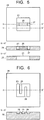
- a plurality of lands (convex potions) 15 are preferably provided.
- the lands 15 are provided for mechanical retention and electrical continuity.
- the lands 15 are preferably provided alternately to uniformize flow of the anode solution.
- the above lands 15 make the anode solution flow path 12 serpentine. Moreover, also for a good discharge of the anode solution in which oxygen (O 2 ) gas is mixed, the lands 15 are preferably provided alternately along the anode solution flow path 12 to make the anode solution flow path 12 serpentine.
- the anode 11 is preferably mainly constituted of a catalyst material (anode catalyst material) capable of oxidizing water (H 2 O) to produce oxygen or hydrogen ions or oxidizing hydroxide ions (OH - ) to produce water or oxygen, and capable of reducing an overvoltage of the above reaction.
- a catalyst material anode catalyst material capable of oxidizing water (H 2 O) to produce oxygen or hydrogen ions or oxidizing hydroxide ions (OH - ) to produce water or oxygen, and capable of reducing an overvoltage of the above reaction.
- a metal such as platinum (Pt), palladium (Pd), or nickel (Ni), an alloy or an intermetallic compound containing the above metals, a binary metal oxide such as a manganese oxide (Mn-O), an iridium oxide (Ir-O), a nickel oxide (Ni-O), a cobalt oxide (Co-O), an iron oxide (Fe-O), a tin oxide (Sn-O), an indium oxide (In-O), a ruthenium oxide (Ru-O), a lithium oxide (Li-O), or a lanthanum oxide (La-O), a ternary metal oxide such as Ni-Co-O, Ni-Fe-O, La-Co-O, Ni-La-O, or Sr-Fe-O, a quaternary metal oxide such as Pb-Ru-Ir-O or La-Sr-Co-O, or a metal complex such as a Ru complex or a Fe complex
- a binary metal oxide such as a
- the anode 11 includes a base material having a structure capable of moving the anode solution or ions between the separator 30 and the anode solution flow path 12, for example, a porous structure such as a mesh material, a punching material, a porous body, or a metal fiber sintered body.
- the base material may be constituted of a metal such as titanium (Ti), nickel (Ni), or iron (Fe), or a metal material such as an alloy (for example, SUS) containing at least one of these metals, or may be constituted of the above-described anode catalyst material.
- the anode catalyst material When the oxide is used as the anode catalyst material, the anode catalyst material preferably adheres to or is stacked on a surface of the base material constituted of the above-described metal material to form a catalyst layer.
- the anode catalyst material preferably has nanoparticles, a nanostructure, a nanowire, or the like for the purpose of increasing the oxidation reaction.
- the nanostructure is a structure in which nanoscale irregularities are formed on a surface of the catalyst material.
- the cathode 22 is an electrode (reduction electrode) which causes a reduction reaction of carbon dioxide (CO 2 ) or a reduction reaction of a carbon compound produced thereby to produce a carbon compound such as carbon monoxide (CO), methane (CH 4 ), ethane (C 2 H 6 ), ethylene (C 2 H 4 ), methanol (CH 3 OH), ethanol (C 2 H 5 OH), or ethylene glycol (C 2 H 6 O 2 ).
- a side reaction in which hydrogen (H 2 ) is produced by a reduction reaction of water (H 2 O) is sometimes caused.
- the cathode 22 has a first surface 22a facing the cathode solution flow path 21 and a second surface 22b facing the CO 2 gas flow path 23.
- the cathode solution flow path 21 is disposed between the cathode 22 and the separator 30 so that the cathode solution as an electrolytic solution is in contact with the cathode 22 and the separator 30.
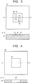
- the cathode solution flow path 21 is constituted by an opening portion provided in a second flow path plate 25.
- a solution inlet port and a solution outlet port whose illustrations are omitted are provided, and via these solution inlet port and solution outlet port, the cathode solution is introduced and discharged by the cathode solution supply system 200.
- the cathode solution flows through in the cathode solution flow path 21 so as to be in contact with the cathode 22 and the separator 30.
- a material having low chemical reactivity and having no conductivity is preferably used.
- an insulating resin material such as an acrylic resin, polyetheretherketone (PEEK), or a fluorocarbon resin.
- a land (convex portion) 26 may be provided in the cathode solution flow path 21.
- the land 26 in the cathode solution flow path 21 is provided in a center portion of the cathode solution flow path 21, and is retained to the second flow path plate 25 by a bridge portion 27 thinner than the land 26 so as not to prevent the cathode solution in the cathode solution flow path 21 from flowing through.
- the number of lands 26 is preferably small in order to reduce cell resistance.
- the CO 2 gas flow path 23 is constituted by a pit (groove portion/concave portion) provided in a third flow path plate 28.
- a material having low chemical reactivity and high conductivity is preferably used for the third flow path plate 28 constituting the CO 2 gas flow path.
- the metal material such as Ti or SUS, carbon, or the like can be cited.
- an inlet port and an outlet port for a solution or gas, screw holes for tightening, and the like, whose illustrations are omitted are provided in front of and behind each of the flow path plates 14, 25, and 28, packing whose illustration is omitted is sandwiched as necessary.
- a gas inlet port and a gas outlet port whose illustrations are omitted are provide, and via these gas inlet port and gas outlet port, CO 2 gas or gas (sometimes collectively referred to simply as CO 2 gas.) containing CO 2 is introduced and discharged by the gas supply system 300.
- the CO 2 gas flows through in the CO 2 gas flow path 23 so as to be in contact with the cathode 22.
- a plurality of lands (convex potions) 29 are preferably provided.
- the lands 29 are provided for the mechanical retention and the electrical continuity.
- the lands 29 are preferably provided alternately, and this makes the CO 2 gas flow path 23 serpentine similarly to the anode solution flow path 12.
- the cathode current collector 24 is electrically in contact with a surface on a side opposite to the cathode 22 of the third flow path plate 28.
- providing the lands 15 and the lands 29 along the anode solution flow path 12 and the CO 2 gas flow path 23 makes it possible to increase a contact area between the anode 11 and the first flow path plate 14 constituting the anode solution flow path 12 and a contact area between the cathode 22 and the third flow path plate 28 constituting the CO 2 gas flow path 23.
- providing the land 26 in the cathode solution flow path 21 makes it possible to increase a contact area between the cathode 22 and the second flow path plate 25 constituting the cathode solution flow path 21.
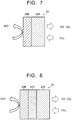
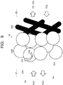
- the cathode 22 has a gas diffusion layer 22A and a cathode catalyst layer 22B provided thereon as illustrated in Fig. 7 . Between the gas diffusion layer 22A and the cathode catalyst layer 22B, as illustrated in Fig. 8 , a porous layer 22C denser than the gas diffusion layer 22A may be disposed. As illustrated in Fig. 9 , the gas diffusion layer 22A is disposed on the CO 2 gas flow path 23 side, and the cathode catalyst layer 22B is disposed on the cathode solution flow path 21 side. The cathode catalyst layer 22B may enter into the gas diffusion layer 22A.
- the cathode catalyst layer 22B preferably has catalyst nanoparticles, a catalyst nanostructure, or the like.
- the gas diffusion layer 22A is constituted by carbon paper, carbon cloth, or the like, for example, and subjected to water repellent treatment.
- the porous layer 22C is constituted by a porous body whose pore size is smaller than that of the carbon paper or the carbon cloth.
- the cathode solution or ions are supplied and discharged from the cathode solution flow path 21.
- the CO 2 gas is supplied from the CO 2 gas flow path 23 and further a product by the reduction reaction of the CO 2 gas is discharged.
- the CO 2 gas reaches the cathode catalyst layer 22B mainly owing to gas diffusion.
- the reduction reaction of CO 2 or the reduction reaction of a carbon compound produced thereby occurs in the vicinity of a boundary between the gas diffusion layer 22A and the cathode catalyst layer 22B or in the vicinity of the cathode catalyst layer 22B which enters into the gas diffusion layer 22A, a gaseous product is discharged mainly from the CO 2 gas flow path 23, and a liquid product is discharged mainly from the cathode solution flow path 21.
- the cathode catalyst layer 22B is preferably constituted of a catalyst material (cathode catalyst material) capable of reducing carbon dioxide to produce a carbon compound and further reducing the carbon compound produced thereby to produce a carbon compound as necessary, and capable of reducing an overvoltage of the above reaction.
- a catalyst material cathode catalyst material
- a metal such as gold (Au), silver (Ag), copper (Cu), platinum (Pt), palladium (Pd), nickel (Ni), cobalt (Co), iron (Fe), manganese (Mn), titanium (Ti), cadmium (Cd), zing (Zn), indium (In), gallium (Ga), lead (Pb), or tin (Sn), a metal material such as an alloy or an intermetallic compound containing at least one of the above metals, a carbon material such as carbon (C), graphene, CNT (carbon nanotube), fullerene, or ketjen black, or a metal complex such as a Ru complex or a Re complex.
- various shapes such as a plate shape, a mesh shape, a wire shape, a particle shape, a porous shape, a thin film shape, and an island shape can be applied.
- the cathode catalyst material constituting the cathode catalyst layer 22B preferably has nanoparticles of the above-described metal material, a nanostructure of the metal material, a nanowire of the metal material, or a composite body in which the nanoparticles of the above-described metal material are supported by a carbon material such as carbon particles, a carbon nanotube, or graphene.
- a carbon material such as carbon particles, a carbon nanotube, or graphene.
- the separator 30 is constituted of an ion exchange membrane or the like capable of moving ions between the anode 11 and the cathode 22 and separating the anode part 10 and the cathode part 20.
- the ion exchange membrane for example, a cation exchange membrane such as Nafion or Flemion, or an anion exchange membrane such as Neosepta, or Selemion can be used.
- the separator 30 is preferably constituted of the anion exchange membrane.
- a glass filter, a porous polymeric membrane, or a porous insulating material may be applied to the separator 30 as long as they are a material capable of moving ions between the anode 11 and the cathode 22.
- the anode solution and the cathode solution as the electrolytic solution are preferably a solution containing at least water (H 2 O). Because carbon dioxide (CO 2 ) is supplied from the CO 2 gas flow path 23, the cathode solution may contain or need not contain carbon dioxide (CO 2 ). To the anode solution and the cathode solution, the same solution may be applied or different solutions may be applied. As a solution used as the anode solution and the cathode solution and containing H 2 O, an aqueous solution containing an arbitrary electrolyte can be cited.
- an aqueous solution containing the electrolyte for example, there can be cited an aqueous solution containing at least one selected from a hydroxide ion (OH - ), a hydrogen ion (H + ), a potassium ion (K + ), a sodium ion (Na + ), a lithium ion (Li + ), a chloride ion (Cl - ), a bromide ion (Br - ), an iodide ion (I-), a nitrate ion (NO 3 - ), a sulfate ion (SO 4 2- ), a phosphate ion (PO 4 2- ), a borate ion (BO 3 3- ), and a hydrogen carbonate ion (HCO 3 - ).
- a hydroxide ion OH -
- H + hydrogen ion
- K + potassium ion
- Na + sodium ion
- Li +
- an alkaline solution in which an electrolyte such as a potassium hydroxide or a sodium hydroxide is dissolved in high concentration is preferably used.
- an ionic liquid which is made of salts of cations such as imidazolium ions or pyridinium ions and anions such as BF 4 - or PF 6 - and which is in a liquid state in a wide temperature range, or its aqueous solution may be used.
- an amine solution of ethanolamine, imidazole, pyridine, or the like, or an aqueous solution thereof.
- amine any of primary amine, secondary amine, and tertiary amine is applicable.
- the anode solution is supplied from the anode solution supply system 100.
- the anode solution supply system 100 circulates the anode solution so that the anode solution flows through in the anode solution flow path 12.
- the anode solution supply system 100 has a pressure control unit 101, an anode solution tank 102, a flow rate control unit (pump) 103, a reference electrode 104, and a pressure gauge 105, and is constituted so that the anode solution circulates in the anode solution flow path 12.
- the anode solution tank 102 is connected to a gas component collection unit which collects a gas component such as oxygen (O 2 ) contained in the circulating anode solution and is not illustrated.
- the anode solution whose flow rate and pressure are controlled in the pressure control unit 101 and the flow rate control unit 103, is introduced to the anode solution flow path 12.
- the cathode solution is supplied from the cathode solution supply system 200.
- the cathode solution supply system 200 circulates the cathode solution so that the cathode solution flows through in the cathode solution flow path 21.
- the cathode solution supply system 200 has a pressure control unit 201, a cathode solution tank 202, a flow rate control unit (pump) 203, a reference electrode 204, and a pressure gauge 205, and is constituted so that the cathode solution circulates in the cathode solution flow path 21.
- the cathode solution tank 202 is connected to a gas component collection unit 206 which collects a gas component such as carbon monoxide (CO) contained in the circulating cathode solution.
- the cathode solution whose flow rate and pressure are controlled in the pressure control unit 201 and the flow rate control unit 203, is introduced to the cathode solution flow path 21.
- the CO 2 gas is supplied from the gas supply system 300.
- the gas supply system 300 has a CO 2 gas cylinder 301, a flow rate control unit 302, a pressure gauge 303, and a pressure control unit 304.
- the CO 2 gas whose flow rate and pressure are controlled in the flow rate control unit 302 and the pressure control unit 304, is introduced to the CO 2 gas flow path 23.
- the gas supply system 300 is connected to the product collection system 400 which collects a product in gas which has flowed through the CO 2 gas flow path 23.
- the product collection system 400 has a gas/liquid separation unit 401 and a product collection unit 402.
- a reduction product such as CO or H 2 contained in the gas which has flowed through the CO 2 gas flow path 23 is accumulated via the gas/liquid separation unit 401 in the product collection unit 402.
- the anode solution and the cathode solution circulate in the anode solution flow path 12 and the cathode solution flow path 21 at a time of an electrolytic reaction operation as described above.
- the anode solution and the cathode solution are discharged to the waste solution collection system 600 so that the anode 11, the anode solution flow path 12, the cathode 22, the cathode solution flow path 21, and the like are exposed from the anode solution and the cathode solution.
- the waste solution collection system 600 has a waste solution collection tank 601 connected to the anode solution flow path 12 and the cathode solution flow path 21.
- Waste solutions of the anode solution and the cathode solution are collected in the waste solution collection tank 601 by opening and closing unillustrated valves. Opening and closing of the valves, or the like is controlled collectively by the control system 500.
- the waste solution collection tank 601 also functions as a collection unit of a rinse solution to be supplied from the refresh material supply unit 700. Moreover, a gaseous substance to be supplied from the refresh material supply unit 700 and to partially contain a liquid substance is also collected by the waste solution collection tank 601 as necessary.
- the refresh material supply unit 700 includes a gaseous substance supply system 710 and a rinse solution (liquid) supply system 720.
- the refresh material supply unit 700 includes supply system 710 which supplies the gaseous substance as a part of the refresh material.
- the gaseous substance supply system 710 has a gas tank 711 which becomes a supply source of a gaseous substance such as air, carbon dioxide, oxygen, nitrogen, or argon, and a pressure control unit 712 which controls a supply pressure of the gaseous substance.
- the rinse solution supply system 720 has a rinse solution tank 721 which becomes a supply source of a rinse solution such as water and a flow rate control unit (pump) 722 which controls a supply flow rate or the like of the rinse solution.
- a flow rate control unit (pump) 722 which controls a supply flow rate or the like of the rinse solution.
- the gaseous substance and rinse solution supply systems 710 and 720 are connected via pipes to the anode solution flow path 12, the cathode solution flow path 21, and the CO 2 gas flow path 23.
- the gaseous substance and the rinse solution are supplied to each of the flow paths 12, 21, and 23 by opening and closing unillustrated valves. Opening and closing of the valves, or the like is controlled collectively by the control system 500.
- Part of the reduction product accumulated in the product collection unit 402 is sent to a reduction performance detection unit 501 of the control system 500.
- a reduction performance detection unit 501 a production amount and a proportion of each product such CO or H 2 in the reduction product are detected.
- the detected production amount and proportion of each product are inputted to a data collection control unit 502 of the control system 500.
- the data collection control unit 502 collects a cell output which is at least one of electrical values (electrical data) of the electrolysis cell 2.
- the cell output of the electrolysis cell 2 contains the Faradaic efficiency of the carbon compound and may further include a cell voltage, a cell current, a cathode potential, and an anode potential.
- the data collection control unit 502 is electrically connected via bi-directional signal lines whose illustration is partially omitted to the pressure control unit 101 and the flow rate control unit 103 of the anode solution supply system 100, the pressure control unit 201 and the flow rate control unit 203 of the cathode solution supply system 200, the flow rate control unit 302 and the pressure control unit 304 of the gas supply system 300, and the pressure control unit 712 and the flow rate control unit 722 of the refresh material supply unit 700 in addition to the reduction performance detection unit 501, and these are collectively controlled. Note that an unillustrated valve is provided on each pipe, and an opening/closing operation of the valve is controlled by a signal from the data collection control unit 502.
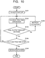
- a start-up step S101 of the electrolytic device 1 is performed.
- the following operation is performed.
- a flow rate and a pressure are controlled by the pressure control unit 101 and the flow rate control unit 103, and the anode solution is introduced to the anode solution flow path 12.
- a flow rate and a pressure are controlled by the pressure control unit 201 and the flow rate control unit 203, and the cathode solution is introduced to the cathode solution flow path 21.
- the gas supply system 300 a flow rate and a pressure are controlled by the flow rate control unit 302 and the pressure control unit 304, and CO 2 gas is introduced to the CO 2 gas flow path 23.
- a CO 2 electrolysis operation step S102 is performed.
- an output from the power supply 40 of the electrolytic device 1 in which the start-up step S101 has been performed is started, and an electric current is supplied by applying voltage between the anode 11 and the cathode 22. Passing the electric current between the anode 11 and the cathode 22 causes an oxidation reaction in the vicinity of the anode 11 and a reduction reaction in the vicinity of the cathode 22 which are presented below.
- CO carbon monoxide
- the carbon compound as the reduction product of carbon dioxide is not limited to carbon monoxide, and may be other carbon compounds such as the above-described organic compounds.
- a reaction process by the electrolysis cell 2 a case of mainly producing hydrogen ions (H + ) and a case of mainly producing hydroxide ions (OH - ) are considered, but it is not limited to either of these reaction processes.
- H + produced in the anode 11 moves in the anode solution existing in the anode 11, the separator 30, and the cathode solution in the cathode solution flow path 21 and reaches the vicinity of the cathode 22.
- the reduction reaction of carbon dioxide (CO 2 ) occurs by electrons (e - ) based on the electric current which is supplied from the power supply 40 to the cathode 22 and H + which moves to the vicinity of the cathode 22.
- CO 2 supplied from the CO 2 gas flow path 23 to the cathode 22 is reduced and CO is produced.
- the reduction reaction of CO 2 is considered to occur in the vicinity of the boundary between the gas diffusion layer 22A and the cathode catalyst layer 22B as described above.
- the cathode solution flowing through the cathode solution flow path 21 enters up to the gas diffusion layer 22A or the cathode catalyst layer 22B has excess water, and thereby a disadvantage such as a decrease in the production amount of CO by the reduction reaction of CO 2 or an increase in the cell voltage occurs.
- Such a decrease in the cell output of the electrolysis cell 2 is also caused by deviation of distribution of ions and residual gas in the vicinities of the anode 11 and the cathode 22, precipitation of an electrolyte in the cathode 22 and the anode 11, further the precipitation of an electrolyte in the anode solution flow path 12 and the cathode solution flow path 21, and the like.
- a step S103 in which a determination is made whether the cell output satisfies request criteria or not is performed.
- the data collection control unit 502 collects the production amount and the proportion of each product and the cell output, which contains the Faradaic efficiency of the carbon compound and may further include the cell voltage, the cell current, the cathode potential, and the anode potential, regularly or continuously as described above. Moreover, in the data collection control unit 502, the request criteria of the cell output are set beforehand, and a determination is made whether collected data satisfies the set request criteria or not. When the collected data satisfies the set request criteria, the CO 2 electrolysis operation S102 is continued without performing a CO 2 electrolysis stop (S104). When the collected data does not satisfy the set request criteria, a refresh operation step S105 is performed.
- the request criteria of the cell output which is collected by the data collection control unit 502 contains the Faradaic efficiency of the carbon compound and may further include an upper limit value of a cell voltage at a time of passing a constant current through the electrolysis cell 2, a lower limit value of a cell current at a time of applying a constant voltage to the electrolysis cell 2.
- the Faradaic efficiency is defined as a proportion of an electric current contributing to production of an intended carbon compound to an entire electric current passing through the electrolysis cell 2.
- the upper limit value of the cell voltage at a time of passing a constant current reaches 150% or more, preferably 120% or more relative to a set value, it is preferable to perform the refresh operation step S105.
- the refresh operation step S105 when the lower limit value of the cell current at a time of applying a constant voltage reaches 50% or less, preferably 80% or less relative to a set value, it is preferable to perform the refresh operation step S105.
- the Faradaic efficiency of the carbon compound becomes 50% or less, preferably 80% or less relative to a set value, it is preferable to perform the refresh operation step S105.
- the refresh operation step S105 is performed when the Faradaic efficiency of the carbon compound, and optionally the cell voltage and/or the cell current, does not satisfy the request criteria. For example, when neither the cell voltage nor the Faradaic efficiency of the carbon compound satisfies the request criteria, the refresh operation step S105 may be performed.
- the refresh operation step S105 is performed when at least one of the cell output does not satisfy the request criteria. In order to perform the CO 2 electrolysis operation step S102 stably, the refresh operation step S105 is preferably performed at an interval of one hour or more.
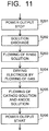
- the refresh operation step S105 is performed according to a flow chart illustrated in Fig. 11 , for example.
- the cathode solution and the anode solution are discharged from the cathode solution flow path 21 and the anode solution flow path 12 (S202).
- the rinse solution is supplied to the cathode solution flow path 21 and the anode solution flow path 12 (S203), and washing is performed.
- the cathode 22 and the anode 11 are dried.
- the cathode solution is introduced to the cathode solution flow path 21
- the anode solution is introduced to the anode solution flow path 12
- CO 2 gas is introduced to the CO 2 gas flow path 23 (S205).
- S206 by starting the output of the power supply 40 (S206), the CO 2 electrolysis operation is resumed.
- gas may be used or the rinse solution may be used.
- the rinse solution supply and flow (S203) are performed in order to prevent precipitation of an electrolyte contained the cathode solution and the anode solution and wash the cathode 22, the anode 11, and each of the flow paths 12 and 21. Therefore, water is preferable for the rinse solution, water having electric conductivity of 1 mS/m or less is more preferable, and water having the electric conductivity of 0.1 mS/m or less is further preferable.
- an acid rinse solution having a low concentration, of sulfuric acid, nitric acid, hydrochloric acid, or the like may be supplied, and thereby the electrolyte may be dissolved.
- a step in which the rinse solution of water is supplied is performed in a step thereafter.
- the supply step of the rinse solution of water is preferably performed.
- Fig. 1 illustrates the rinse solution supply system 720 having one rinse solution tank 721, but when a plurality of rinse solutions such as water and the acid rinse solution are used, a plurality of rinse solution tanks 721 corresponding thereto are used.
- the gas to be used for the gas supply and flow step S204 preferably contains at least one of air, carbon dioxide, oxygen, nitrogen, and argon. Moreover, gas having low chemical reactivity is preferably used. Form such a point, air, nitrogen, and argon are preferably used, and further nitrogen and argon are more preferable.
- the supply of the rinse solution and gas for refresh is not limited only to the cathode solution flow path 21 and the anode solution flow path 12, and in order to wash a surface of the cathode 22 in contact with the CO 2 gas flow path 23, the rinse solution and the gas may be supplied to the CO 2 gas flow path 23. In order to dry the cathode 22 also from the surface side in contact with the CO 2 gas flow path 23, it is effective to supply the gas to the CO 2 gas flow path 23.
- a case of supplying the rinse solution and gas for refresh to both the anode part 10 and the cathode part 20 is described in the above, but the rinse solution and gas for refresh may be supplied to only one of either the anode part 10 or the cathode part 20.
- the Faradaic efficiency of the carbon compound varies depending on a contact region between the cathode solution and CO 2 in the gas diffusion layer 22A and the cathode catalyst layer 22B of the cathode 22. In such a case, only by supplying the rinse solution and gas for refresh to only the cathode part 20, the Faradaic efficiency of the carbon compound is sometimes recovered.
- the rinse solution and gas for refresh may be supplied to only one of either the anode part 10 or the cathode part 20.
- the cell output is sometimes recovered only by drying the anode 11 and the cathode 22.
- only the gas for refresh may be supplied to at least one of the anode part 10 and the cathode part 20.
- the refresh operation step S105 changes are variously possible according to an operation condition, a tendency, or the like of the electrolytic device 1.
- the electrolytic device 1 of the first arrangement based on whether the cell output of the electrolysis cell 2 satisfies the request criteria or not, a determination is made whether the CO 2 electrolysis operation step S102 is continued or whether the refresh operation step S105 is performed.
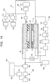
- Fig. 12 is a view illustrating a configuration of a carbon dioxide electrolytic device according to a second arrangement
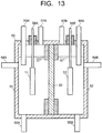
- Fig. 13 is a sectional view illustrating a configuration of an electrolysis cell in the electrolytic device illustrated in Fig. 12
- an electrolysis cell 2X includes: an electrolysis cell 2X; an anode solution supply system 100 which supplies an anode solution to the electrolysis cell 2X; a cathode solution supply system 200 which supplies a cathode solution to the electrolysis cell 2X; a gas supply system 300 which supplies carbon dioxide (CO 2 ) gas to the electrolysis cell 2X; a product collection system 400 which collects a product produced by a reduction reaction in the electrolysis cell 2X; a control system 500 which detects a type and a production amount of the collected product and, performs control of the product and control of a refresh operation; a waste solution collection system 600 which collects a waste solution of the cathode solution or the anode solution; and a refresh material supply unit 700 which recovers an anode, a cathode, or the like of the electrolysis cell 2X, similarly to the carbon dioxide electrolytic device 1 according to the first arrangement.
- the carbon dioxide electrolytic device 1X illustrated in Fig. 12 includes basically the same configuration as that of the electrolytic device 1 illustrated in Fig. 1 except that a configuration of the electrolysis cell 2X is different.
- the electrolysis cell 2X includes a reaction tank 53 having an anode solution tank 51, a cathode solution tank 52, and a separator 30 which separates these anode solution tank 51 and cathode solution tank 52 as illustrated in Fig. 13 .
- the anode solution tank 51 has a solution inlet port 54A and a solution discharge port 55A connected to the anode solution supply system 100, and a gas inlet port 56A and a gas discharge port 57A.
- An anode solution is introduced from and discharged to the anode solution supply system 100 to/from the anode solution tank 51.
- An anode 11 is disposed in the anode solution tank 51 so as to be immersed in the anode solution.
- the anode 11 is connected via a current introduction portion 58A to a power supply 40.
- the cathode solution tank 52 has a solution inlet port 54B and a solution discharge port 55B connected to the cathode solution supply system 200, and a gas inlet port 56B and a gas discharge port 57B connected to the gas supply system 300.
- a cathode solution is introduced from and discharged to the cathode solution supply system 200 to/from the cathode solution tank 52.
- CO 2 gas is introduced from the gas supply system 300 to the cathode solution tank 52, and gas containing a gaseous product is sent to the product collection system 400.
- the CO 2 gas is preferably released from the gas inlet port 56B into the cathode solution.
- a cathode 22 is disposed in the cathode solution tank 52 so as to be immersed in the cathode solution.
- the cathode 22 is connected via a current introduction portion 58B to the power supply 40.
- a gaseous substance supply system 710 of the refresh material supply unit 700 is connected via pipes to the gas inlet port 56A of the anode solution tank 51 and the gas inlet port 56B of the cathode solution tank 52.
- a rinse solution supply system 720 of the refresh material supply unit 700 is connected via pipes to the solution inlet port 54A of the anode solution tank 51 and the solution inlet port 54B of the cathode solution tank 52.
- the solution discharge port 55A of the anode solution tank 51 and the solution discharge port 55B of the cathode solution tank 52 are connected via pipes to the waste solution collection system 600.
- the gas discharge port 57A of the anode solution tank 51 and the gas discharge port 57B of the cathode solution tank 52 are connected via pipes to the waste solution collection system 600, and recovery via the waste solution collection system 600 into an unillustrated waste gas collection tank or release to atmosphere is performed.
- Composing materials or the like of the respective parts are the same as those of the electrolytic device 1 of the first arrangement, and details are as described above.
- a start-up step S101 and a CO 2 electrolysis operation step S102 of the electrolytic device 1X are performed similarly to those in the electrolytic device 1 of the first arrangement except that supply modes of the anode solution, the cathode solution, and the CO 2 gas are different.
- a determination step S103 whether to satisfy the request criteria of the cell output or not is also performed similarly to that in the electrolytic device 1 of the first arrangement. That is, when the Faradaic efficiency of a carbon compound, and optionally the cell voltage and/or the cell current, does not satisfy the request criteria, a cell output is determined as not satisfying the request criteria, and a refresh operation step S105 is performed.
- the refresh operation step S105 is performed as follows.
- a CO 2 reduction reaction is stopped by stopping an output of a power supply 40.
- the anode solution and the cathode solution are discharged from the anode solution tank 51 and the cathode solution tank 52.
- a rinse solution is supplied from the rinse solution supply system 720 to the anode solution tank 51 and the cathode solution tank 52, and the anode 11 and the cathode 22 are washed.
- gas is supplied from the gaseous substance supply system 710 to the anode solution tank 51 and the cathode solution tank 52, and the anode 11 and the cathode 22 are dried.
- the gas and rinse solution to be used for the refresh operation step S105 are the same as those in the first arrangement.
- the anode solution is introduced to the anode solution tank 51, the cathode solution is introduced to the cathode solution tank 52, and further CO 2 gas is supplied in the cathode solution. Then, by starting the output of the power supply 40 (S206), the CO 2 electrolysis operation is resumed.
- gas may be used or the rinse solution may be used. However, amounts of the cathode solution and the anode solution are larger compared with those in the first arrangement.
- the rinse solution is preferably supplied after discharging the solutions using the gas.
- the refresh operation may be performed as follows.
- the current introduction portions 58 (58A, 58B) provided in an upper portion of the electrolysis cell 2X are detached, and the anode 11 and the cathode 22 are taken outside to be exposed from the anode solution and the cathode solution.
- the anode 11 and the cathode 22 are immersed in the rinse solution to be washed.
- the anode 11 and the cathode 22 are taken out from the rinse solution and dried by spraying the gas.
- the current introduction portions 58 (58A, 58B) are attached, and the anode 11 and the cathode 22 are immersed in the anode solution and the cathode solution.
- the electrolytic device 1X of the second arrangement based on whether the cell output of the electrolysis cell 2X satisfies the request criteria or not, a determination is made whether the CO 2 electrolysis operation is continued or whether the refresh operation is performed.
- deviation of distribution of ions and residual gas in the vicinities of the anode 11 and the cathode 22, which becomes a decrease factor of the cell output is eliminated, and precipitation of an electrolyte in the anode 11 and the cathode 22, and the like are removed. Accordingly, by resuming the CO 2 electrolysis operation after the refresh operation step, the cell output of the electrolysis cell 2X can be recovered. Repeating the CO 2 electrolysis operation and the refresh operation based on the request criteria of the cell output makes it possible to maintain CO 2 electrolysis performance by the electrolytic device 1X for a long stretch of time.
- Fig. 14 is a view illustrating a configuration of a carbon dioxide electrolytic device according to a third arrangement
- Fig. 15 is a sectional view illustrating a configuration of an electrolysis cell in the electrolytic device illustrated in Fig. 14 .
- an electrolysis cell 2Y includes: an electrolysis cell 2Y; an anode solution supply system 100 which supplies an anode solution to the electrolysis cell 2Y; a gas supply system 300 which supplies carbon dioxide (CO 2 ) gas to the electrolysis cell 2Y; a product collection system 400 which collects a product produced by a reduction reaction in the electrolysis cell 2Y; a control system 500 which detects a type and a production amount of the collected product and, performs control of the product and control of a refresh operation; a waste solution collection system 600 which collects a waste solution of the anode solution; and a refresh material supply unit 700 which recovers an anode, a cathode, or the like of the electrolysis cell 2Y, similarly to the carbon dioxide electrolytic device 1 according to the first arrangement.
- an electrolysis cell 2Y includes: an electrolysis cell 2Y; an anode solution supply system 100 which supplies an anode solution to the electrolysis cell 2Y; a gas supply system 300 which supplies carbon dioxide (CO 2 ) gas to the electrolysis
- the carbon dioxide electrolytic device 1Y illustrated in Fig. 14 includes basically the same configuration as that of the electrolytic device 1 illustrated in Fig. 1 except that the configuration of the electrolysis cell 2X is different and a cathode solution supply system 200 is not included.
- the electrolysis cell 2Y includes an anode part 10, a cathode part 20, and a separator 30 as illustrated in Fig. 15 .
- the anode part 10 includes an anode 11, an anode solution flow path 12, and an anode current collector 13.
- the cathode part 20 includes a cathode 22, a CO 2 gas flow path 23, and a cathode current collector 24.
- a power supply 40 is connected via a current introduction member to the anode 11 and the cathode 22.
- the anode 11 preferably has a first surface 11a in contact with the separator 30 and a second surface 11b facing the anode solution flow path 12.
- the first surface 11a of the anode 11 is in close contact with the separator 30.
- An anode solution flow path 12 is constituted by a pit (groove portion/concave portion) provided in a flow path plate 14.
- An anode solution flows through in the anode solution flow path 12 so as to be in contact with the anode 11.
- the anode current collector 13 is electrically in contact with a surface on a side opposite to the anode 11 of the flow path plate 14 constituting the anode solution flow path 12.
- the cathode 22 has a first surface 22a in contact with the separator 30 and a second surface 22b facing the CO 2 gas flow path 23.
- the CO 2 gas flow path 23 is constituted by a pit (groove portion/concave portion) provided in a flow path plate 28.
- the cathode current collector 24 is electrically in contact with a surface on a side opposite to the cathode 22 of the flow path plate 28 constituting the CO 2 gas flow path 23.
- a gaseous substance supply system 710 and a rinse solution supply system 720 of the refresh material supply unit 700 are connected via pipes to the anode solution flow path 12 and the CO 2 gas flow path 23.
- the anode solution flow path 12 and the CO 2 gas flow path 23 are connected via pipes to the waste solution collection system 600.
- a rinse solution discharged from the anode solution flow path 12 and the CO 2 gas flow path 23 is recovered into a waste solution collection tank 601 of the waste solution collection system 600.
- Gas for refresh discharged from the anode solution flow path 12 and the CO 2 gas flow path 23 is recovered via the waste solution collection system 600 into an unillustrated waste gas collection tank or released to atmosphere.
- Composing materials or the like of the respective parts are the same as those of the electrolytic device 1 of the first arrangement, and details are as described above.
- a start-up step S101 and a CO 2 electrolysis operation step S102 of the electrolytic device 1Y are performed similarly to those in the electrolytic device 1 of the first arrangement except that supply of a cathode solution is not performed.
- a reduction reaction of CO 2 in the cathode part 20 is performed by CO 2 supplied from the CO 2 gas flow path 23 and the anode solution which permeates the cathode 22 via the separator 30.
- a determination step S103 whether to satisfy the request criteria of the cell output or not is also performed similarly to that in the electrolytic device 1 of the first arrangement.
- a cell output is determined as not satisfying the request criteria, and a refresh operation step S105 is performed.
- the refresh operation step S105 is performed as follows.
- the CO 2 reduction reaction is stopped by stopping an output of a power supply 40.
- the anode solution is discharged from the anode solution flow path 12.
- the rinse solution is supplied from the rinse solution supply system 720 to the anode solution flow path 12 and the CO 2 gas flow path 23, and the anode 11 and the cathode 22 are washed.
- the anode 11 and the cathode 22 are dried by supplying gas from the gaseous substance supply system 710 to the anode solution flow path 12 and the CO 2 gas flow path 23.
- the gas and rinse solution to be used for the refresh operation step are the same as those in the first arrangement.
- the electrolytic device 1Y of the third arrangement based on whether the cell output of the electrolysis cell 2Y satisfies the request criteria or not, a determination is made whether the CO 2 electrolysis operation is continued or whether the refresh operation is performed.
- the cell output of the electrolysis cell 2Y can be recovered. Repeating the above CO 2 electrolysis operation and refresh operation based on the request criteria of the cell output makes it possible to maintain CO 2 electrolysis performance by the electrolytic device 1Y for a long stretch of time.
- An electrolytic device illustrated in Fig. 1 and Fig. 2 was fabricated as follows, and electrolysis performance of carbon dioxide was examined.
- a cathode to which gold nanoparticle-supported carbon particles were applied was produced by the following process.
- a coating solution in which the gold nanoparticle-supported carbon particles and pure water, a Nafion solution, and ethylene glycol were mixed was produced.
- An average particle diameter of the gold nanoparticle was 8.7 nm, and a supported amount thereof was 18.9 mass%.
- An air brush was filled with this coating solution, spray coating was performed using Ar gas on the carbon paper on which the porous layer was provided.
- Flowing water washing was performed by pure water for 30 minutes after the coating, and thereafter organic matter such as ethylene glycol was removed by oxidation through immersing in a hydrogen peroxide solution, This was cut into a size of 2 ⁇ 2 cm to be set as the cathode. Note that a coating amount of Au was estimated at about 0.2 mg/cm 2 from a mixing amount of the gold nanoparticles and the carbon particles in the coating solution.
- an electrode in which IrO 2 nanoparticles which became a catalyst were applied to Ti mesh was used.
- the one in which IrO 2 /Ti mesh was cut into 2 ⁇ 2 cm was used.
- the electrolysis cell 2 was produced by being stacked in order of the cathode current collector 24, the CO 2 gas flow path 23 (the third flow path plate 28), the cathode 22, the cathode solution flow path 21 (the second flow path plate 25), the separator 30, the anode 11, the anode solution flow path 12 (the first flow path plate 14), and the anode current collector 13 from the top, being sandwiched by the support plates not illustrated, and further being tightened by the bolts, as illustrated in Fig. 2 .
- an anion exchange membrane brand name: Selemion, manufactured by ASAHI GLASS CO., LTD.
- the IrO 2 /Ti mesh of the anode 11 was brought in close contact with the anion exchange membrane.
- a thickness of the cathode solution flow path 21 was set to 1 mm. Note that an evaluation temperature was set to room temperature.
- the electrolytic device 1 illustrated in Fig. 1 was fabricated using the above-described electrolysis cell 2, and the electrolytic device was operated under the following condition.
- CO 2 gas was supplied to the CO 2 gas flow path of the electrolysis cell at 20 sccm
- an aqueous potassium hydroxide solution (concentration 1 M KOH) was introduced to the cathode solution flow path at a flow rate of 5 mL/min
- the aqueous potassium hydroxide solution (concentration 1 M KOH) was introduced to the anode solution flow path at a flow rate of 20 mL/min.
- a 600 mA constant current (constant current density 150 mA/cm 2 ) was passed between the anode and the cathode using the power supply, an electrolytic reaction of CO 2 was performed, and a cell voltage at that time were measured to be collected by the data collection control unit. Moreover, part of gas outputted from the CO 2 gas flow path was collected, and production amounts of CO gas produced by a reduction reaction of CO 2 and H 2 gas produced by a reduction reaction of water were analyzed by a gas chromatograph. A partial current density and Faradaic efficiency which was a ratio between the entire current density and the partial current density of CO or H 2 from the gas production amounts in the data collection control unit were calculated to be collected. As request criteria of a cell output of a refresh operation, CO Faradaic efficiency was set to 50% or less, and a cell voltage at a time of passing a constant current was set to 3 V or more corresponding to 120% or more relative to an initial value 2.5 V.
- Table 1 presents a cell voltage, CO Faradaic efficiency and H 2 Faradaic efficiency which are collected every about 20 minutes. Because a value of 50% or less such as 24% was detected in the CO Faradaic efficiency after 55 minutes, the refresh operation was performed. Pure water was made to flow through the cathode solution flow path and the anode solution flow path of the electrolysis cell, and the cathode, the cathode solution flow path, the anode, and the anode solution flow path were washed. Next, air gas was made to flow through the cathode solution flow path and the anode solution flow path, which were dried.
Landscapes
- Chemical & Material Sciences (AREA)
- Organic Chemistry (AREA)
- Engineering & Computer Science (AREA)
- Metallurgy (AREA)
- Electrochemistry (AREA)
- Materials Engineering (AREA)
- Chemical Kinetics & Catalysis (AREA)
- Inorganic Chemistry (AREA)
- Automation & Control Theory (AREA)
- Life Sciences & Earth Sciences (AREA)
- Sustainable Development (AREA)
- Analytical Chemistry (AREA)
- Electrolytic Production Of Non-Metals, Compounds, Apparatuses Therefor (AREA)
Claims (8)
- Kohlendioxid-Elektrolysevorrichtung (1), umfassend:eine Elektrolysezelle (2), enthaltend eine Kathode (22) zum Reduzieren von Kohlendioxid und dadurch zum Herstellen einer Kohlenstoffverbindung, eine Anode (11) zum Oxidieren von Wasser oder Hydroxidionen und dadurch zum Herstellen von Sauerstoff, eine Kohlendioxid-Zufuhreinheit zum Zuführen von Kohlendioxid zu der Kathode (22), eine Elektrolytlösungs-Zufuhreinheit zum Zuführen einer Wasser enthaltenden Elektrolytlösung zu mindestens einer der Kathode (22) und der Anode (11), und einen Separator (30) zum Trennen der Anode (11) und der Kathode (22);eine Stromversorgung (40), die mit der Anode (11) und der Kathode (22) verbunden ist;eine Reaktionssteuereinheit, um eine Reduktionsreaktion des Kohlendioxids in der Kathode (22) und eine Oxidationsreaktion des Wassers oder der Hydroxidionen in der Anode (11) zu bewirken, indem ein elektrischer Strom von der Stromversorgung (40) zu der Anode (11) und der Kathode (22) geleitet wird;eine Auffrischungsmaterial-Zufuhreinheit, enthaltend eine Gaszufuhreinheit zum Zuführen einer gasförmigen Substanz als Teil des Auffrischungsmaterials zu mindestens einer der Anode (11) und der Kathode (22) und eine Flüssigkeitszufuhreinheit zum Zuführen einer Spüllösung als Teil des Auffrischungsmaterials zu mindestens einer der Anode (11) und der Kathode (22);eine Datensammlungssteuereinheit, konfiguriert zum Sammeln eines Zelloutputs der Elektrolysezelle (2), der den Faraday'schen Wirkungsgrad der Kohlenstoffverbindung enthält, der als Anteil eines elektrischen Stroms, der zur Produktion der Kohlenstoffverbindung beiträgt, zu einem gesamten elektrischen Strom, der durch die Elektrolysezelle (2) fließt, definiert ist, und zum Bestimmen, ob der gesammelte Zelloutput, enthaltend den Faraday'schen Wirkungsgrad der Kohlenstoffverbindung, Anforderungskriterien des Zelloutputs, enthaltend den Faraday'schen Wirkungsgrad der Kohlenstoffverbindung, erfüllt; undeine Auffrischungssteuereinheit, die die Zufuhr des elektrischen Stroms von der Stromversorgung (40) durch die Reaktionssteuereinheit stoppt und die Zufuhr des Kohlendioxids und der Elektrolytlösung stoppt und die Auffrischungsmaterial-Zufuhreinheit betreibt auf Basis eines Bestimmungsergebnisses durch die Datensammlungssteuereinheit, dass der gesammelte Zelloutput, enthaltend den Faraday'schen Wirkungsgrad der Kohlenstoffverbindung, den Anforderungskriterien des Zelloutputs, enthaltend den Faraday'schen Wirkungsgrad der Kohlenstoffverbindung, nicht erfüllt.
- Vorrichtung (1) gemäß Anspruch 1, wobei die Flüssigkeits-Zufuhreinheit eine erste Flüssigkeits-Zufuhreinheit zum Zuführen einer sauren Spüllösung zu mindestens einer der Anode (11) und der Kathode (22) und eine zweite Flüssigkeits-Zufuhreinheit zum Zuführen von Wasser zu mindestens einer der Anode (11) und der Kathode (22) umfasst.
- Vorrichtung (1) gemäß Anspruch 1 oder Anspruch 2, wobei die gasförmige Substanz mindestens eine Substanz, ausgewählt aus der Gruppe, bestehend aus Luft, Sauerstoff, Stickstoff und Argon, enthält.
- Vorrichtung (1) gemäß einem der Ansprüche 1 bis 3,
wobei die Kohlendioxid-Zufuhreinheit einen Gasströmungspfad (23) aufweist, durch den das Kohlendioxid so geströmt wird, dass es in Kontakt mit der Kathode (22) ist, und
wobei die Elektrolytlösungs-Zufuhreinheit einen Kathodenlösungs-Strömungspfad (21), durch den eine Kathodenlösung als die Elektrolytlösung so geströmt wird, dass sie in Kontakt mit der Kathode (22) ist, und einen Anodenlösungs-Strömungspfad (12), durch den eine Anodenlösung als die Elektrolytlösung so geströmt wird, dass sie in Kontakt mit der Anode (11) ist, aufweist. - Vorrichtung (1) gemäß Anspruch 4,
wobei die Anode (11) eine erste Oberfläche (11a) in Kontakt mit dem Separator (30) und eine zweite Oberfläche (11b), die dem Anodenlösungs-Strömungspfad (12) zugewandt ist, so dass die Anodenlösung in Kontakt mit der Anode (11) ist, aufweist, und
wobei die Kathode (22) eine erste Oberfläche (22a), die dem Kathodenlösungs-Strömungspfad (21) zugewandt ist, und eine zweite Oberfläche (22b), die dem Gasströmungspfad (23) zugewandt ist, aufweist, und der Kathodenlösungs-Strömungspfad (21) zwischen dem Separator (30) und der Kathode (22) angeordnet ist, so dass die Kathodenlösung in Kontakt mit dem Separator (30) und der Kathode (22) ist. - Vorrichtung (1) gemäß einem der Ansprüche 1 bis 3,
wobei die Elektrolytlösungs-Versorgungseinheit einen Kathodenlösungstank (202) zur Aufnahme einer Kathodenlösung als Elektrolytlösung, in die die Kathode (22) eingetaucht ist, und einen Anodenlösungstank (102) zur Aufnahme einer Anodenlösung als Elektrolytlösung, in die die Anode eingetaucht ist, aufweist, und
wobei die Kohlendioxid-Zufuhreinheit ein Kohlendioxid-Zufuhrsystem zum Zuführen des Kohlendioxids zu der Kathodenlösung aufweist. - Vorrichtung (1) gemäß einem der Ansprüche 1 bis 3,
wobei die Kohlendioxid-Zufuhreinheit einen Gasströmungspfad (23) aufweist, durch den das Kohlendioxid so geströmt wird, dass es in Kontakt mit der Kathode (22) ist,
wobei die Elektrolytlösungs-Zufuhreinheit einen Anodenlösungs-Strömungspfad (12) aufweist, durch den eine Anodenlösung als die Elektrolytlösung so geströmt wird, dass sie in Kontakt mit der Anode (11) ist, und wobei die Kathode (22) und die Anode (11) in Kontakt mit dem Separator (30) stehen. - Kohlendioxid-Elektrolyseverfahren, umfassend:das Herstellen einer Elektrolysezelle (2) mit einer Anode (11) und einer Kathode (22);das Zuführen von Kohlendioxid zu der Kathode (22) in der Elektrolysezelle (2), und das Zuführen einer Wasser enthaltenden Elektrolytlösung zu mindestens einer der Kathode (22) und der Anode (11) in der Elektrolysezelle (2) ;das Zuführen eines elektrischen Stroms von einer Stromversorgung (40) zu der Anode (11) und der Kathode (22), das Reduzieren von Kohlendioxid, um eine Kohlenstoffverbindung in einer Umgebung der Kathode (22) herzustellen, und das Oxidieren von Wasser oder Hydroxidionen, um Sauerstoff in einer Umgebung der Anode (11) herzustellen;das Sammeln eines Zelloutputs der Elektrolysezelle (2), der den Faraday'schen Wirkungsgrad der Kohlenstoffverbindung enthält, der als Anteil eines elektrischen Stroms, der zur Produktion der Kohlenstoffverbindung beiträgt, zu einem gesamten elektrischen Strom, der durch die Elektrolysezelle (2) fließt, definiert ist, und das Bestimmen, ob der gesammelte Zelloutput, enthaltend den Faraday'schen Wirkungsgrad der Kohlenstoffverbindung, Anforderungskriterien des Zelloutputs, enthaltend den Faraday'schen Wirkungsgrad der Kohlenstoffverbindung, erfüllt;das Stoppen der Zufuhr des elektrischen Stroms von der Stromversorgung (40) und das Stoppen der Zufuhr des Kohlendioxids und der Elektrolytlösung auf Basis eines Bestimmungsergebnisses, dass der gesammelte Zelloutput, enthaltend den Faraday'schen Wirkungsgrad der Kohlenstoffverbindung, den Anforderungskriterien des Zelloutputs, enthaltend den Faraday'schen Wirkungsgrad der Kohlenstoffverbindung, nicht erfüllt; undauf Basis des Bestimmungsergebnisses das Zuführen einer Spüllösung und einer gasförmigen Substanz in dieser Reihenfolge als Auffrischungsmaterial zu mindestens einer der Anode (11) und der Kathode (22), freigelegt von der Elektrolytlösung.
Applications Claiming Priority (1)
| Application Number | Priority Date | Filing Date | Title |
|---|---|---|---|
| JP2017054570A JP6672211B2 (ja) | 2017-03-21 | 2017-03-21 | 二酸化炭素電解装置および二酸化炭素電解方法 |
Publications (2)
| Publication Number | Publication Date |
|---|---|
| EP3378968A1 EP3378968A1 (de) | 2018-09-26 |
| EP3378968B1 true EP3378968B1 (de) | 2021-04-28 |
Family
ID=59858971
Family Applications (1)
| Application Number | Title | Priority Date | Filing Date |
|---|---|---|---|
| EP17191058.1A Active EP3378968B1 (de) | 2017-03-21 | 2017-09-14 | Elektrolysevorrichtung für kohlendioxid und elektrolyseverfahren für kohlendioxid |
Country Status (4)
| Country | Link |
|---|---|
| US (1) | US10208385B2 (de) |
| EP (1) | EP3378968B1 (de) |
| JP (1) | JP6672211B2 (de) |
| CN (1) | CN108624905A (de) |
Families Citing this family (49)
| Publication number | Priority date | Publication date | Assignee | Title |
|---|---|---|---|---|
| JP6784776B2 (ja) | 2016-05-03 | 2020-11-11 | オーパス 12 インコーポレイテッドOpus 12 Incorporated | Co2、coおよび他の化学化合物の電気化学反応のための先進的構造を有するリアクタ |
| US12359325B2 (en) | 2016-05-03 | 2025-07-15 | Twelve Benefit Corporation | Membrane electrode assembly for COx reduction |
| JP6672193B2 (ja) * | 2017-02-02 | 2020-03-25 | 株式会社東芝 | 二酸化炭素の電解セルと電解装置 |
| JP6845114B2 (ja) * | 2017-09-20 | 2021-03-17 | 株式会社東芝 | 二酸化炭素電解装置および二酸化炭素電解方法 |
| WO2019144135A1 (en) | 2018-01-22 | 2019-07-25 | Opus-12 Incorporated | System and method for carbon dioxide reactor control |
| US12320022B2 (en) | 2018-01-22 | 2025-06-03 | Twelve Benefit Corporation | System and method for carbon dioxide reactor control |
| JP6823000B2 (ja) | 2018-03-20 | 2021-01-27 | 株式会社東芝 | 二酸化炭素電解装置 |
| JP6783814B2 (ja) | 2018-03-22 | 2020-11-11 | 株式会社東芝 | 二酸化炭素電解装置および二酸化炭素電解方法 |
| JP6818711B2 (ja) | 2018-03-22 | 2021-01-20 | 株式会社東芝 | 二酸化炭素電解装置および二酸化炭素電解方法 |
| CN112969822A (zh) | 2018-08-20 | 2021-06-15 | 泰利斯纳诺能量公司 | 用于制备高压且高纯度的气态氢的模块化电解单元 |
| JP6933622B2 (ja) | 2018-09-14 | 2021-09-08 | 株式会社東芝 | 二酸化炭素電解装置 |
| JP6951309B2 (ja) | 2018-09-18 | 2021-10-20 | 株式会社東芝 | 二酸化炭素電解装置および二酸化炭素電解方法 |
| EP3628757A1 (de) * | 2018-09-25 | 2020-04-01 | Paul Scherrer Institut | Verfahren zur beseitigung von nichtproton-kationischen verunreinigungen aus einer elektrochemischen zelle sowie elektrochemische zelle |
| BR112021010368A2 (pt) | 2018-11-28 | 2021-08-24 | Opus 12 Incorporated | Eletrolisador e método de uso |
| US10590548B1 (en) * | 2018-12-18 | 2020-03-17 | Prometheus Fuels, Inc | Methods and systems for fuel production |
| WO2020132064A1 (en) | 2018-12-18 | 2020-06-25 | Opus 12 Inc. | Electrolyzer and method of use |
| WO2020146402A1 (en) | 2019-01-07 | 2020-07-16 | Opus 12 Inc. | System and method for methane production |
| JP7029420B2 (ja) * | 2019-02-21 | 2022-03-03 | 株式会社東芝 | 二酸化炭素電解セル用電極触媒層、ならびにそれを具備する、電解セルおよび二酸化炭素電解用電解装置 |
| CN114174558B9 (zh) * | 2019-05-25 | 2025-07-01 | 塞格德大学 | 模块化电解器堆叠和在升高的压力下以高转化率将二氧化碳转化成气态产物的方法 |
| CN110344071B (zh) * | 2019-08-14 | 2020-11-17 | 碳能科技(北京)有限公司 | 电还原co2装置和方法 |
| JP7204619B2 (ja) * | 2019-09-17 | 2023-01-16 | 株式会社東芝 | 二酸化炭素電解装置及び二酸化炭素電解方法 |
| JP7204620B2 (ja) * | 2019-09-17 | 2023-01-16 | 株式会社東芝 | 電気化学反応装置 |
| JP7140731B2 (ja) * | 2019-09-17 | 2022-09-21 | 株式会社東芝 | 電気化学反応装置及び有価物製造システム |
| EP4065753A1 (de) | 2019-11-25 | 2022-10-05 | Twelve Benefit Corporation | <sup2/>? <sub2/>?x?membranelektrodenanordnung für co-reduktion |
| EP4077766A1 (de) * | 2019-12-20 | 2022-10-26 | Avantium Knowledge Centre B.V. | Bildung von ameisensäure mit hilfe einer indiumhaltigen katalytischen elektrode |
| JP7242601B2 (ja) * | 2020-03-23 | 2023-03-20 | 株式会社東芝 | 二酸化炭素電解装置 |
| DE102020206341A1 (de) * | 2020-05-20 | 2021-11-25 | Siemens Aktiengesellschaft | Korrosionsschutz in einem CO2-Elektrolyse-Stack |
| DE102020206447A1 (de) | 2020-05-25 | 2021-11-25 | Siemens Aktiengesellschaft | Verfahren zur Steuerung einer Elektrolysevorrichtung |
| AU2020458213A1 (en) | 2020-07-17 | 2023-03-09 | Szegedi Tudományegyetem | Process and system to enhance and sustain electrolyser performance of carbon-dioxide electrolysers |
| JP7247150B2 (ja) | 2020-09-02 | 2023-03-28 | 株式会社東芝 | 二酸化炭素電解装置および二酸化炭素電解方法 |
| US12421392B2 (en) | 2020-10-20 | 2025-09-23 | Twelve Benefit Corporation | Ionic polymers and copolymers |
| WO2022087167A1 (en) | 2020-10-20 | 2022-04-28 | Opus 12 Incorporated | Semi-interpenetrating and crosslinked polymers and membranes thereof |
| BR112023016931A2 (pt) | 2021-02-23 | 2023-11-07 | Twelve Benefit Corp | Procedimento de recuperação para eletrolisadores de óxido de carbono |
| JP7203875B2 (ja) * | 2021-03-04 | 2023-01-13 | 本田技研工業株式会社 | 電気化学反応装置、二酸化炭素の還元方法、及び炭素化合物の製造方法 |
| JP7520754B2 (ja) | 2021-03-15 | 2024-07-23 | 株式会社東芝 | 二酸化炭素電解装置及び二酸化炭素電解方法 |
| JP7542467B2 (ja) * | 2021-03-18 | 2024-08-30 | 株式会社東芝 | 二酸化炭素電解装置および二酸化炭素電解装置の運転方法 |
| JP7329011B2 (ja) * | 2021-03-19 | 2023-08-17 | 出光興産株式会社 | 固体電解質形電解装置、および、そのメンテナンス方法 |
| JP7145264B1 (ja) * | 2021-03-23 | 2022-09-30 | 本田技研工業株式会社 | 二酸化炭素処理装置、二酸化炭素処理方法及び炭素化合物の製造方法 |
| CN113184961B (zh) * | 2021-05-31 | 2022-07-12 | 山东瑞克环境科技有限公司 | 一种有机物废水电催化降解装置 |
| CN113637987B (zh) * | 2021-08-16 | 2022-08-30 | 辽宁科技学院 | 一种二氧化碳电解还原装置及其还原方法 |
| JP7551585B2 (ja) | 2021-09-15 | 2024-09-17 | 株式会社東芝 | 二酸化炭素電解装置 |
| CN116219457A (zh) * | 2021-12-02 | 2023-06-06 | 中国科学院过程工程研究所 | 一种新型高温电化学制尿素电解池装置及应用 |
| JP2024546680A (ja) | 2021-12-08 | 2024-12-26 | トゥエルブ ベネフィット コーポレーション | エチレン生成のためのシステム及び方法 |
| EP4507886A2 (de) | 2022-04-15 | 2025-02-19 | Twelve Benefit Corporation | Cox-elektrolysezellenströmungsfelder und gasdiffusionsschichten |
| MA68017A1 (fr) * | 2022-04-21 | 2025-11-28 | Lg Chem, Ltd. | Séparateur et cellule de conversion électrochimique le comprenant |
| CA3264781A1 (en) | 2022-08-12 | 2024-02-15 | Twelve Benefit Corporation | ACETIC ACID PRODUCTION |
| US12305304B2 (en) | 2022-10-13 | 2025-05-20 | Twelve Benefit Corporation | Interface for carbon oxide electrolyzer bipolar membrane |
| US12378685B2 (en) | 2022-12-22 | 2025-08-05 | Twelve Benefit Corporation | Surface modification of metal catalysts with hydrophobic ligands or ionomers |
| US12460310B2 (en) | 2023-04-04 | 2025-11-04 | Twelve Benefit Corporation | Integrated systems employing carbon oxide electrolysis in aluminum production |
Citations (1)
| Publication number | Priority date | Publication date | Assignee | Title |
|---|---|---|---|---|
| US4185142A (en) * | 1978-08-09 | 1980-01-22 | Diamond Shamrock Corporation | Oxygen electrode rejuvenation methods |
Family Cites Families (22)
| Publication number | Priority date | Publication date | Assignee | Title |
|---|---|---|---|---|
| JPS4820115B1 (de) * | 1969-05-09 | 1973-06-19 | ||
| JPS61166991A (ja) * | 1985-01-18 | 1986-07-28 | Asahi Glass Co Ltd | 食塩電解方法 |
| EP1297200B1 (de) | 2000-07-06 | 2007-01-03 | Akzo Nobel N.V. | Aktivierung einer kathode |
| US7011738B2 (en) | 2000-07-06 | 2006-03-14 | Akzo Nobel N.V. | Activation of a cathode |
| JP3769492B2 (ja) | 2001-11-07 | 2006-04-26 | 三井化学株式会社 | ガス拡散電極の性能回復方法 |
| JP2005052762A (ja) * | 2003-08-06 | 2005-03-03 | Meidensha Corp | ガス処理方法とそのシステム |
| KR100767942B1 (ko) * | 2003-10-17 | 2007-10-17 | 닛코킨조쿠 가부시키가이샤 | 무전해 구리도금액 |
| US7507323B1 (en) | 2004-09-17 | 2009-03-24 | Maytal Tech, Inc. | Self-cleaning chlorine generator with pH control |
| EP1951933A4 (de) * | 2005-10-13 | 2011-08-24 | Mantra Energy Alternatives Ltd | Kontinuierliche elektrochemische gleichstrom-reduktion von kohlendioxid |
| JP2009190016A (ja) | 2008-02-13 | 2009-08-27 | Linxross Inc | 水浄化処理用電解キャパシター内のバイオフィルム除去及び防止方法 |
| JP5308282B2 (ja) * | 2008-10-06 | 2013-10-09 | クロリンエンジニアズ株式会社 | オゾン発生装置の運転方法及びオゾン発生装置 |
| JP5295753B2 (ja) * | 2008-12-26 | 2013-09-18 | 株式会社神戸製鋼所 | オゾン水生成装置 |
| WO2012128148A1 (ja) * | 2011-03-18 | 2012-09-27 | 国立大学法人長岡技術科学大学 | 二酸化炭素の還元固定化システム、二酸化炭素の還元固定化方法、及び有用炭素資源の製造方法 |
| AR091406A1 (es) * | 2012-06-12 | 2015-02-04 | Jx Nippon Oil & Energy Corp | Dispositivo de reduccion electroquimica y metodo para fabricar hidruro o compuesto hidrocarbonado aromatico o compuesto aromatico heterociclico con contenido de nitrogeno |
| JP6236392B2 (ja) * | 2012-10-01 | 2017-11-22 | 日本製紙株式会社 | 多硫化物製造用電解槽による連続電解方法及びそれを実施する電解装置 |
| EP3029177B1 (de) * | 2013-07-30 | 2019-03-20 | JX Nippon Oil & Energy Corporation | Elektrochemische reduktionsvorrichtung und verfahren zur herstellung einer hydrierten aromatischen verbindung |
| WO2015037625A1 (ja) * | 2013-09-12 | 2015-03-19 | 独立行政法人宇宙航空研究開発機構 | 固体高分子形発電または電解方法およびシステム |
| WO2015177950A1 (ja) * | 2014-05-20 | 2015-11-26 | 株式会社 東芝 | 光電気化学反応装置 |
| DE102015203245A1 (de) * | 2015-02-24 | 2016-08-25 | Siemens Aktiengesellschaft | Abscheidung eines kupferhaltigen, Kohlenwasserstoffe entwickelnden Elektrokatalysators auf Nicht-Kupfer-Substraten |
| GB201509769D0 (en) | 2015-06-03 | 2015-07-22 | Imp Innovations Ltd | Apparatus and method for production of oxidants |
| DE102015215309A1 (de) | 2015-08-11 | 2017-02-16 | Siemens Aktiengesellschaft | Präparationstechnik von kohlenwasserstoffselektiven Gasdiffusionselektroden basierend auf Cu-haltigen-Katalysatoren |
| WO2017033131A1 (en) | 2015-08-27 | 2017-03-02 | M/S Faith Innovations | Electrochemical activation system |
-
2017
- 2017-03-21 JP JP2017054570A patent/JP6672211B2/ja active Active
- 2017-09-13 US US15/703,364 patent/US10208385B2/en active Active
- 2017-09-14 EP EP17191058.1A patent/EP3378968B1/de active Active
- 2017-09-18 CN CN201710840482.5A patent/CN108624905A/zh active Pending
Patent Citations (1)
| Publication number | Priority date | Publication date | Assignee | Title |
|---|---|---|---|---|
| US4185142A (en) * | 1978-08-09 | 1980-01-22 | Diamond Shamrock Corporation | Oxygen electrode rejuvenation methods |
Also Published As
| Publication number | Publication date |
|---|---|
| CN108624905A (zh) | 2018-10-09 |
| US10208385B2 (en) | 2019-02-19 |
| EP3378968A1 (de) | 2018-09-26 |
| JP2018154901A (ja) | 2018-10-04 |
| US20180274109A1 (en) | 2018-09-27 |
| JP6672211B2 (ja) | 2020-03-25 |
Similar Documents
| Publication | Publication Date | Title |
|---|---|---|
| EP3378968B1 (de) | Elektrolysevorrichtung für kohlendioxid und elektrolyseverfahren für kohlendioxid | |
| EP3626858B1 (de) | Kohlendioxidelektrolysevorrichtung und verfahren zur elektrolyse von kohlendioxid | |
| US11286573B2 (en) | Carbon dioxide electrolytic device and method of electrolyzing carbon dioxide | |
| US11230772B2 (en) | Carbon dioxide electrolytic device and method of electrolyzing carbon dioxide | |
| US10961632B2 (en) | Carbon dioxide electrolytic device and method of electrolyzing carbon dioxide | |
| US11130723B2 (en) | Carbon dioxide electrolytic device | |
| EP3623501B1 (de) | Kohlendioxidelektrolysevorrichtung | |
| JP7242601B2 (ja) | 二酸化炭素電解装置 | |
| EP3358042B1 (de) | Elektrolysezelle und elektrolysevorrichtung für kohlendioxid | |
| US12241170B2 (en) | Carbon dioxide electrolytic device | |
| US12031219B2 (en) | Carbon dioxide electrolytic device and method of electrolyzing carbon dioxide |
Legal Events
| Date | Code | Title | Description |
|---|---|---|---|
| PUAI | Public reference made under article 153(3) epc to a published international application that has entered the european phase |
Free format text: ORIGINAL CODE: 0009012 |
|
| STAA | Information on the status of an ep patent application or granted ep patent |
Free format text: STATUS: REQUEST FOR EXAMINATION WAS MADE |
|
| 17P | Request for examination filed |
Effective date: 20170914 |
|
| AK | Designated contracting states |
Kind code of ref document: A1 Designated state(s): AL AT BE BG CH CY CZ DE DK EE ES FI FR GB GR HR HU IE IS IT LI LT LU LV MC MK MT NL NO PL PT RO RS SE SI SK SM TR |
|
| AX | Request for extension of the european patent |
Extension state: BA ME |
|
| STAA | Information on the status of an ep patent application or granted ep patent |
Free format text: STATUS: EXAMINATION IS IN PROGRESS |
|
| 17Q | First examination report despatched |
Effective date: 20190926 |
|
| REG | Reference to a national code |
Ref country code: DE Ref legal event code: R079 Ref document number: 602017037480 Country of ref document: DE Free format text: PREVIOUS MAIN CLASS: C25B0001100000 Ipc: C25B0001000000 |
|
| RIC1 | Information provided on ipc code assigned before grant |
Ipc: C25B 1/10 20060101ALI20201104BHEP Ipc: C25B 9/08 20060101ALI20201104BHEP Ipc: C25B 15/02 20060101ALI20201104BHEP Ipc: C25B 3/04 20060101ALI20201104BHEP Ipc: C25B 1/00 20060101AFI20201104BHEP |
|
| GRAP | Despatch of communication of intention to grant a patent |
Free format text: ORIGINAL CODE: EPIDOSNIGR1 |
|
| STAA | Information on the status of an ep patent application or granted ep patent |
Free format text: STATUS: GRANT OF PATENT IS INTENDED |
|
| INTG | Intention to grant announced |
Effective date: 20201218 |
|
| GRAS | Grant fee paid |
Free format text: ORIGINAL CODE: EPIDOSNIGR3 |
|
| GRAA | (expected) grant |
Free format text: ORIGINAL CODE: 0009210 |
|
| STAA | Information on the status of an ep patent application or granted ep patent |
Free format text: STATUS: THE PATENT HAS BEEN GRANTED |
|
| AK | Designated contracting states |
Kind code of ref document: B1 Designated state(s): AL AT BE BG CH CY CZ DE DK EE ES FI FR GB GR HR HU IE IS IT LI LT LU LV MC MK MT NL NO PL PT RO RS SE SI SK SM TR |
|
| REG | Reference to a national code |
Ref country code: GB Ref legal event code: FG4D |
|
| REG | Reference to a national code |
Ref country code: CH Ref legal event code: EP |
|
| REG | Reference to a national code |
Ref country code: AT Ref legal event code: REF Ref document number: 1387128 Country of ref document: AT Kind code of ref document: T Effective date: 20210515 |
|
| REG | Reference to a national code |
Ref country code: DE Ref legal event code: R096 Ref document number: 602017037480 Country of ref document: DE |
|
| REG | Reference to a national code |
Ref country code: IE Ref legal event code: FG4D |
|
| REG | Reference to a national code |
Ref country code: LT Ref legal event code: MG9D |
|
| REG | Reference to a national code |
Ref country code: AT Ref legal event code: MK05 Ref document number: 1387128 Country of ref document: AT Kind code of ref document: T Effective date: 20210428 |
|
| PG25 | Lapsed in a contracting state [announced via postgrant information from national office to epo] |
Ref country code: FI Free format text: LAPSE BECAUSE OF FAILURE TO SUBMIT A TRANSLATION OF THE DESCRIPTION OR TO PAY THE FEE WITHIN THE PRESCRIBED TIME-LIMIT Effective date: 20210428 Ref country code: LT Free format text: LAPSE BECAUSE OF FAILURE TO SUBMIT A TRANSLATION OF THE DESCRIPTION OR TO PAY THE FEE WITHIN THE PRESCRIBED TIME-LIMIT Effective date: 20210428 Ref country code: NL Free format text: LAPSE BECAUSE OF FAILURE TO SUBMIT A TRANSLATION OF THE DESCRIPTION OR TO PAY THE FEE WITHIN THE PRESCRIBED TIME-LIMIT Effective date: 20210428 Ref country code: HR Free format text: LAPSE BECAUSE OF FAILURE TO SUBMIT A TRANSLATION OF THE DESCRIPTION OR TO PAY THE FEE WITHIN THE PRESCRIBED TIME-LIMIT Effective date: 20210428 Ref country code: AT Free format text: LAPSE BECAUSE OF FAILURE TO SUBMIT A TRANSLATION OF THE DESCRIPTION OR TO PAY THE FEE WITHIN THE PRESCRIBED TIME-LIMIT Effective date: 20210428 Ref country code: BG Free format text: LAPSE BECAUSE OF FAILURE TO SUBMIT A TRANSLATION OF THE DESCRIPTION OR TO PAY THE FEE WITHIN THE PRESCRIBED TIME-LIMIT Effective date: 20210728 |
|
| PG25 | Lapsed in a contracting state [announced via postgrant information from national office to epo] |
Ref country code: SE Free format text: LAPSE BECAUSE OF FAILURE TO SUBMIT A TRANSLATION OF THE DESCRIPTION OR TO PAY THE FEE WITHIN THE PRESCRIBED TIME-LIMIT Effective date: 20210428 Ref country code: RS Free format text: LAPSE BECAUSE OF FAILURE TO SUBMIT A TRANSLATION OF THE DESCRIPTION OR TO PAY THE FEE WITHIN THE PRESCRIBED TIME-LIMIT Effective date: 20210428 Ref country code: NO Free format text: LAPSE BECAUSE OF FAILURE TO SUBMIT A TRANSLATION OF THE DESCRIPTION OR TO PAY THE FEE WITHIN THE PRESCRIBED TIME-LIMIT Effective date: 20210728 Ref country code: PT Free format text: LAPSE BECAUSE OF FAILURE TO SUBMIT A TRANSLATION OF THE DESCRIPTION OR TO PAY THE FEE WITHIN THE PRESCRIBED TIME-LIMIT Effective date: 20210830 Ref country code: PL Free format text: LAPSE BECAUSE OF FAILURE TO SUBMIT A TRANSLATION OF THE DESCRIPTION OR TO PAY THE FEE WITHIN THE PRESCRIBED TIME-LIMIT Effective date: 20210428 Ref country code: LV Free format text: LAPSE BECAUSE OF FAILURE TO SUBMIT A TRANSLATION OF THE DESCRIPTION OR TO PAY THE FEE WITHIN THE PRESCRIBED TIME-LIMIT Effective date: 20210428 Ref country code: IS Free format text: LAPSE BECAUSE OF FAILURE TO SUBMIT A TRANSLATION OF THE DESCRIPTION OR TO PAY THE FEE WITHIN THE PRESCRIBED TIME-LIMIT Effective date: 20210828 Ref country code: GR Free format text: LAPSE BECAUSE OF FAILURE TO SUBMIT A TRANSLATION OF THE DESCRIPTION OR TO PAY THE FEE WITHIN THE PRESCRIBED TIME-LIMIT Effective date: 20210729 |
|
| REG | Reference to a national code |
Ref country code: NL Ref legal event code: MP Effective date: 20210428 |
|
| PG25 | Lapsed in a contracting state [announced via postgrant information from national office to epo] |
Ref country code: SK Free format text: LAPSE BECAUSE OF FAILURE TO SUBMIT A TRANSLATION OF THE DESCRIPTION OR TO PAY THE FEE WITHIN THE PRESCRIBED TIME-LIMIT Effective date: 20210428 Ref country code: SM Free format text: LAPSE BECAUSE OF FAILURE TO SUBMIT A TRANSLATION OF THE DESCRIPTION OR TO PAY THE FEE WITHIN THE PRESCRIBED TIME-LIMIT Effective date: 20210428 Ref country code: EE Free format text: LAPSE BECAUSE OF FAILURE TO SUBMIT A TRANSLATION OF THE DESCRIPTION OR TO PAY THE FEE WITHIN THE PRESCRIBED TIME-LIMIT Effective date: 20210428 Ref country code: DK Free format text: LAPSE BECAUSE OF FAILURE TO SUBMIT A TRANSLATION OF THE DESCRIPTION OR TO PAY THE FEE WITHIN THE PRESCRIBED TIME-LIMIT Effective date: 20210428 Ref country code: CZ Free format text: LAPSE BECAUSE OF FAILURE TO SUBMIT A TRANSLATION OF THE DESCRIPTION OR TO PAY THE FEE WITHIN THE PRESCRIBED TIME-LIMIT Effective date: 20210428 Ref country code: RO Free format text: LAPSE BECAUSE OF FAILURE TO SUBMIT A TRANSLATION OF THE DESCRIPTION OR TO PAY THE FEE WITHIN THE PRESCRIBED TIME-LIMIT Effective date: 20210428 Ref country code: ES Free format text: LAPSE BECAUSE OF FAILURE TO SUBMIT A TRANSLATION OF THE DESCRIPTION OR TO PAY THE FEE WITHIN THE PRESCRIBED TIME-LIMIT Effective date: 20210428 |
|
| REG | Reference to a national code |
Ref country code: DE Ref legal event code: R097 Ref document number: 602017037480 Country of ref document: DE |
|
| PLBE | No opposition filed within time limit |
Free format text: ORIGINAL CODE: 0009261 |
|
| STAA | Information on the status of an ep patent application or granted ep patent |
Free format text: STATUS: NO OPPOSITION FILED WITHIN TIME LIMIT |
|
| 26N | No opposition filed |
Effective date: 20220131 |
|
| REG | Reference to a national code |
Ref country code: CH Ref legal event code: PL |
|
| REG | Reference to a national code |
Ref country code: BE Ref legal event code: MM Effective date: 20210930 |
|
| GBPC | Gb: european patent ceased through non-payment of renewal fee |
Effective date: 20210914 |
|
| PG25 | Lapsed in a contracting state [announced via postgrant information from national office to epo] |
Ref country code: IS Free format text: LAPSE BECAUSE OF FAILURE TO SUBMIT A TRANSLATION OF THE DESCRIPTION OR TO PAY THE FEE WITHIN THE PRESCRIBED TIME-LIMIT Effective date: 20210828 Ref country code: MC Free format text: LAPSE BECAUSE OF FAILURE TO SUBMIT A TRANSLATION OF THE DESCRIPTION OR TO PAY THE FEE WITHIN THE PRESCRIBED TIME-LIMIT Effective date: 20210428 Ref country code: AL Free format text: LAPSE BECAUSE OF FAILURE TO SUBMIT A TRANSLATION OF THE DESCRIPTION OR TO PAY THE FEE WITHIN THE PRESCRIBED TIME-LIMIT Effective date: 20210428 |
|
| PG25 | Lapsed in a contracting state [announced via postgrant information from national office to epo] |
Ref country code: LU Free format text: LAPSE BECAUSE OF NON-PAYMENT OF DUE FEES Effective date: 20210914 Ref country code: IT Free format text: LAPSE BECAUSE OF FAILURE TO SUBMIT A TRANSLATION OF THE DESCRIPTION OR TO PAY THE FEE WITHIN THE PRESCRIBED TIME-LIMIT Effective date: 20210428 Ref country code: IE Free format text: LAPSE BECAUSE OF NON-PAYMENT OF DUE FEES Effective date: 20210914 Ref country code: GB Free format text: LAPSE BECAUSE OF NON-PAYMENT OF DUE FEES Effective date: 20210914 Ref country code: FR Free format text: LAPSE BECAUSE OF NON-PAYMENT OF DUE FEES Effective date: 20210930 Ref country code: BE Free format text: LAPSE BECAUSE OF NON-PAYMENT OF DUE FEES Effective date: 20210930 |
|
| PG25 | Lapsed in a contracting state [announced via postgrant information from national office to epo] |
Ref country code: LI Free format text: LAPSE BECAUSE OF NON-PAYMENT OF DUE FEES Effective date: 20210930 Ref country code: CH Free format text: LAPSE BECAUSE OF NON-PAYMENT OF DUE FEES Effective date: 20210930 |
|
| PG25 | Lapsed in a contracting state [announced via postgrant information from national office to epo] |
Ref country code: CY Free format text: LAPSE BECAUSE OF FAILURE TO SUBMIT A TRANSLATION OF THE DESCRIPTION OR TO PAY THE FEE WITHIN THE PRESCRIBED TIME-LIMIT Effective date: 20210428 |
|
| PG25 | Lapsed in a contracting state [announced via postgrant information from national office to epo] |
Ref country code: HU Free format text: LAPSE BECAUSE OF FAILURE TO SUBMIT A TRANSLATION OF THE DESCRIPTION OR TO PAY THE FEE WITHIN THE PRESCRIBED TIME-LIMIT; INVALID AB INITIO Effective date: 20170914 |
|
| PG25 | Lapsed in a contracting state [announced via postgrant information from national office to epo] |
Ref country code: MK Free format text: LAPSE BECAUSE OF FAILURE TO SUBMIT A TRANSLATION OF THE DESCRIPTION OR TO PAY THE FEE WITHIN THE PRESCRIBED TIME-LIMIT Effective date: 20210428 |
|
| PG25 | Lapsed in a contracting state [announced via postgrant information from national office to epo] |
Ref country code: TR Free format text: LAPSE BECAUSE OF FAILURE TO SUBMIT A TRANSLATION OF THE DESCRIPTION OR TO PAY THE FEE WITHIN THE PRESCRIBED TIME-LIMIT Effective date: 20210428 |
|
| PG25 | Lapsed in a contracting state [announced via postgrant information from national office to epo] |
Ref country code: MT Free format text: LAPSE BECAUSE OF FAILURE TO SUBMIT A TRANSLATION OF THE DESCRIPTION OR TO PAY THE FEE WITHIN THE PRESCRIBED TIME-LIMIT Effective date: 20210428 |
|
| PGFP | Annual fee paid to national office [announced via postgrant information from national office to epo] |
Ref country code: DE Payment date: 20250702 Year of fee payment: 9 |