EP3379112A1 - Getriebe für ein kraftfahrzeug, das eine durch einen kipphebel verschiebbare gabel umfasst - Google Patents
Getriebe für ein kraftfahrzeug, das eine durch einen kipphebel verschiebbare gabel umfasst Download PDFInfo
- Publication number
- EP3379112A1 EP3379112A1 EP18156853.6A EP18156853A EP3379112A1 EP 3379112 A1 EP3379112 A1 EP 3379112A1 EP 18156853 A EP18156853 A EP 18156853A EP 3379112 A1 EP3379112 A1 EP 3379112A1
- Authority
- EP
- European Patent Office
- Prior art keywords
- rocker
- gearbox
- spring
- oscillating arm
- axis
- Prior art date
- Legal status (The legal status is an assumption and is not a legal conclusion. Google has not performed a legal analysis and makes no representation as to the accuracy of the status listed.)
- Withdrawn
Links
- 230000010355 oscillation Effects 0.000 claims description 8
- 238000006243 chemical reaction Methods 0.000 claims description 7
- 238000006073 displacement reaction Methods 0.000 claims description 4
- 238000005422 blasting Methods 0.000 description 3
- 238000013459 approach Methods 0.000 description 2
- 230000007935 neutral effect Effects 0.000 description 2
- 238000005553 drilling Methods 0.000 description 1
- 230000000694 effects Effects 0.000 description 1
- 210000003127 knee Anatomy 0.000 description 1
- 238000012986 modification Methods 0.000 description 1
- 230000004048 modification Effects 0.000 description 1
- 230000002040 relaxant effect Effects 0.000 description 1
Images

Classifications
-
- F—MECHANICAL ENGINEERING; LIGHTING; HEATING; WEAPONS; BLASTING
- F16—ENGINEERING ELEMENTS AND UNITS; GENERAL MEASURES FOR PRODUCING AND MAINTAINING EFFECTIVE FUNCTIONING OF MACHINES OR INSTALLATIONS; THERMAL INSULATION IN GENERAL
- F16H—GEARING
- F16H63/00—Control outputs from the control unit to change-speed- or reversing-gearings for conveying rotary motion or to other devices than the final output mechanism
- F16H63/02—Final output mechanisms therefor; Actuating means for the final output mechanisms
- F16H63/30—Constructional features of the final output mechanisms
- F16H63/302—Final output mechanisms for reversing
-
- F—MECHANICAL ENGINEERING; LIGHTING; HEATING; WEAPONS; BLASTING
- F16—ENGINEERING ELEMENTS AND UNITS; GENERAL MEASURES FOR PRODUCING AND MAINTAINING EFFECTIVE FUNCTIONING OF MACHINES OR INSTALLATIONS; THERMAL INSULATION IN GENERAL
- F16H—GEARING
- F16H61/00—Control functions within control units of change-speed- or reversing-gearings for conveying rotary motion ; Control of exclusively fluid gearing, friction gearing, gearings with endless flexible members or other particular types of gearing
- F16H61/24—Providing feel, e.g. to enable selection
-
- F—MECHANICAL ENGINEERING; LIGHTING; HEATING; WEAPONS; BLASTING
- F16—ENGINEERING ELEMENTS AND UNITS; GENERAL MEASURES FOR PRODUCING AND MAINTAINING EFFECTIVE FUNCTIONING OF MACHINES OR INSTALLATIONS; THERMAL INSULATION IN GENERAL
- F16H—GEARING
- F16H63/00—Control outputs from the control unit to change-speed- or reversing-gearings for conveying rotary motion or to other devices than the final output mechanism
- F16H63/02—Final output mechanisms therefor; Actuating means for the final output mechanisms
- F16H63/30—Constructional features of the final output mechanisms
- F16H2063/3089—Spring assisted shift, e.g. springs for accumulating energy of shift movement and release it when clutch teeth are aligned
-
- F—MECHANICAL ENGINEERING; LIGHTING; HEATING; WEAPONS; BLASTING
- F16—ENGINEERING ELEMENTS AND UNITS; GENERAL MEASURES FOR PRODUCING AND MAINTAINING EFFECTIVE FUNCTIONING OF MACHINES OR INSTALLATIONS; THERMAL INSULATION IN GENERAL
- F16H—GEARING
- F16H63/00—Control outputs from the control unit to change-speed- or reversing-gearings for conveying rotary motion or to other devices than the final output mechanism
- F16H63/02—Final output mechanisms therefor; Actuating means for the final output mechanisms
- F16H63/30—Constructional features of the final output mechanisms
- F16H63/3013—Constructional features of the final output mechanisms the final output mechanism being characterised by linkages converting movement, e.g. into opposite direction by a pivoting lever linking two shift rods
-
- F—MECHANICAL ENGINEERING; LIGHTING; HEATING; WEAPONS; BLASTING
- F16—ENGINEERING ELEMENTS AND UNITS; GENERAL MEASURES FOR PRODUCING AND MAINTAINING EFFECTIVE FUNCTIONING OF MACHINES OR INSTALLATIONS; THERMAL INSULATION IN GENERAL
- F16H—GEARING
- F16H63/00—Control outputs from the control unit to change-speed- or reversing-gearings for conveying rotary motion or to other devices than the final output mechanism
- F16H63/02—Final output mechanisms therefor; Actuating means for the final output mechanisms
- F16H63/30—Constructional features of the final output mechanisms
- F16H63/3016—Final output mechanisms varying the leverage or force ratio
Definitions
- the present invention relates to a gearbox for a motor vehicle, and a motor vehicle equipped with such a gearbox.
- Manually operated type gearboxes for motor vehicles generally comprise two parallel shafts supporting pinions of gears producing different gear ratios, to transmit the movement of the engine to the drive wheels in several forward gears.
- An additional shaft carrying sprockets interposed between parallel shaft gears, makes it possible to reverse the direction of travel giving a reverse gear.
- Axially sliding sleeves interposed between free pinions carried by the parallel shafts, slide by sliding towards a free pinion a synchronization and then a interconnection of this pinion on its shaft in order to engage a gear ratio.
- a type of control known sliding sleeves presented in particular by the document EP-A2-0790443 , comprises for each sleeve a control fork engaged in a circular groove of this sleeve, which is guided by an axis parallel to the shafts.
- a control shaft driven in rotation and translation by a speed control lever operated by the driver successively performs a selection movement to select a range, then a movement to move the sleeve bound to this range.
- blasting systems each comprising a positioning ball pushed by a spring in recesses, to maintain the ranges in their positions of dead point and engagement ratios.
- these types of blasting provide little or no no ergonomic assistance for the displacement of the sleeve, comprising the delivery of a force assisting the synchronization movement and commitment of the report.
- the ball positioning can be mounted on small balls forming a ball bearing, which reduce friction by improving ergonomic assistance.
- this system is complex to achieve, and requires a larger race with a longer cam including adapted slopes.
- a known positioning system For movements comprising only two stable end positions, in particular for reversing passage, a known positioning system comprises a toggle spring acting on a passage rocker, which compresses when leaving a position and then relaxes as it approaches. to the other position to maintain it. In this way the spring maintains each end position, and delivers an ergonomic aid by relaxing to assist the engagement of the gear.
- the present invention is intended in particular to avoid these problems of the prior art.
- a gearbox for a motor vehicle comprising a fork moved by a pivoting rocker in a direction between two end positions to engage a ratio of this box, and a toggle spring acting on the rocker which is successively compressed and extended from one end position to the other,
- this gearbox being remarkable in that it comprises an oscillating arm comprising links with the rocker and a housing of the gearbox ensuring that the oscillating arm a pivoting in the direction opposite to that of the rocker, the spring being connected to the rocker and the oscillating arm at two points describing a stroke in opposite directions.
- the gearbox according to the invention may further comprise one or more of the following characteristics, which may be combined with each other.
- the swing arm is connected to the rocker and the casing by two parallel axes.
- the gearbox may comprise successively in the direction of the same transverse axis, a pivot of the rocker, an oscillation axis of the oscillating arm fixed to this rocker, and a reaction axis fixed to the housing and adjusted in a drilling of the swingarm.
- gearbox may comprise successively in the direction of the transverse axis, a first end of the spring attached to the end of the oscillating arm opposite the axis of oscillation, then the second end of this spring.
- the oscillating arm comprises a sheet laid flat on the rocker.
- the housing may comprise a shape covering both the rocker and the swing arm, supporting the pivot and the reaction axis.
- the spring comprises several contiguous turns ending at ends oriented tangentially.
- the movement of the rocker can bring the ends of the spring closer to one another and then a spacing of these ends.
- the invention also relates to a motor vehicle equipped with a gearbox comprising any one of the preceding features.
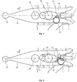
- the figures 1 and 2 have forks 2 for passing forward gears, fixed on longitudinal axes 4 guided in the housing of the gearbox 40, including recesses 16 receiving a log ball systems to fix their operating positions.
- a not shown selection lever actuated by the gearshift lever operated by the driver, acts in a circular groove of the control shaft 6 to effect an axial sliding selection of this shaft.
- One of the ball joints 10 applies to the control shaft 6 a rotation effecting a passage of the reports.
- the other ball 10 causes a mass of inertia external to the gearbox.
- the selection is made by the vertical displacement of a passage finger 12 fitting in a recess of a plate 14 connected to a longitudinal axis 4, the passage through a rotation of the finger driving the selected axis.
- a rocker 24 arranged in a transverse direction, is formed by a cut sheet comprising in a central part a vertical pivot 26 connected to the casing 40.
- the rocker 24 has at one end shown on the right in the figures, a hollow receiving the finger passage 12, and at the other end a boss connecting it to a reverse fork 20 guided by a longitudinal reverse axis 22.
- the rocker 24 reverses the movement of the passage finger 12 to make two end positions of the reverse fork 20, comprising on one side conventionally called back side, indicated by the arrow "AR", a neutral position, and the other the gear ratio commitment.
- An oscillating arm 30 formed by a sheet laid flat on the rocker 24, comprises a vertical oscillation axis 32 fixed to this rocker, which is arranged on the transverse axis T connecting the rocker pivot 26 to the control shaft 6, to the right at a small distance from this pivot.
- a toggle spring 36 comprising a wire wound on several contiguous turns ending in two tangent ends, has a first end 42 fixed on the right end of the oscillating arm 30, a little behind the transverse axis T, at a point disposed to the right at a distance B from the reaction axis 34.
- the distance B is slightly greater than the distance A.
- the second end 44 of the toggle spring 36 is attached to the rocker 24 on the transverse axis T, just next to the right end of the oscillating arm 30.
- the oscillation axis 32 connected to the rocker 24 moves rearward following a fifth stroke C5 towards the rear. Since the fixed reaction axis 34 is substantially at the center of the oscillation arm 30, this arm oscillates, and the first end of the spring 44 moves forwardly along a third stroke C3 equal to the fifth stroke C5 multiplied by the ratio distances B / A.
- the spring 36 provides both without using a blasting system, maintaining the end positions of the rocker 24, and an ergonomic aid for engaging the reverse gear during its relaxation.
Landscapes
- Engineering & Computer Science (AREA)
- General Engineering & Computer Science (AREA)
- Mechanical Engineering (AREA)
- Gear-Shifting Mechanisms (AREA)
Applications Claiming Priority (1)
| Application Number | Priority Date | Filing Date | Title |
|---|---|---|---|
| FR1752475A FR3064328B1 (fr) | 2017-03-24 | 2017-03-24 | Boite de vitesses pour vehicule automobile comprenant une fourchette deplacee par un basculeur |
Publications (1)
| Publication Number | Publication Date |
|---|---|
| EP3379112A1 true EP3379112A1 (de) | 2018-09-26 |
Family
ID=58779183
Family Applications (1)
| Application Number | Title | Priority Date | Filing Date |
|---|---|---|---|
| EP18156853.6A Withdrawn EP3379112A1 (de) | 2017-03-24 | 2018-02-15 | Getriebe für ein kraftfahrzeug, das eine durch einen kipphebel verschiebbare gabel umfasst |
Country Status (2)
| Country | Link |
|---|---|
| EP (1) | EP3379112A1 (de) |
| FR (1) | FR3064328B1 (de) |
Citations (4)
| Publication number | Priority date | Publication date | Assignee | Title |
|---|---|---|---|---|
| FR39397E (fr) * | 1927-10-05 | 1931-10-19 | Maybach Motorenbau Gmbh | Changement de vitesse à deux régimes pour voitures motrices |
| FR812460A (fr) * | 1935-10-16 | 1937-05-11 | Gen Motors Corp | Mécanismes de transmission et leurs commandes, notamment pour automobiles |
| DE2521139A1 (de) * | 1975-05-13 | 1976-11-25 | Kloeckner Humboldt Deutz Ag | Durch federkraft verstellbare schaltvorrichtung |
| EP0790443A2 (de) | 1996-02-17 | 1997-08-20 | Ford-Werke Aktiengesellschaft | Schaltvorrichtung ohne Leergangbewegung während einer Einrückbewegung des Rückwärtsganges |
-
2017
- 2017-03-24 FR FR1752475A patent/FR3064328B1/fr active Active
-
2018
- 2018-02-15 EP EP18156853.6A patent/EP3379112A1/de not_active Withdrawn
Patent Citations (4)
| Publication number | Priority date | Publication date | Assignee | Title |
|---|---|---|---|---|
| FR39397E (fr) * | 1927-10-05 | 1931-10-19 | Maybach Motorenbau Gmbh | Changement de vitesse à deux régimes pour voitures motrices |
| FR812460A (fr) * | 1935-10-16 | 1937-05-11 | Gen Motors Corp | Mécanismes de transmission et leurs commandes, notamment pour automobiles |
| DE2521139A1 (de) * | 1975-05-13 | 1976-11-25 | Kloeckner Humboldt Deutz Ag | Durch federkraft verstellbare schaltvorrichtung |
| EP0790443A2 (de) | 1996-02-17 | 1997-08-20 | Ford-Werke Aktiengesellschaft | Schaltvorrichtung ohne Leergangbewegung während einer Einrückbewegung des Rückwärtsganges |
Also Published As
| Publication number | Publication date |
|---|---|
| FR3064328B1 (fr) | 2019-11-08 |
| FR3064328A1 (fr) | 2018-09-28 |
Similar Documents
| Publication | Publication Date | Title |
|---|---|---|
| US8276473B2 (en) | Sift-drum apparatus and four wheeled vehicle with the same | |
| WO1999057463A1 (fr) | Boite de vitesses compacte | |
| WO2011148065A1 (fr) | Boite de vitesses a double embrayage comportant une liaison de transfert et un rapport de marche arriere | |
| FR2512754A1 (fr) | Prise de force d'entrainement du type de transmission a double accouplement incorpore | |
| FR2831634A1 (fr) | Boite de vitesses a selection masquee | |
| CN101198515A (zh) | 无级变速器 | |
| FR2940773A1 (fr) | Dispositif de transmission pour engin roulant automoteur | |
| EP4240990B1 (de) | Betätigungsanordnung und system zur verriegelung zweier getriebegabelwellen | |
| FR3064328B1 (fr) | Boite de vitesses pour vehicule automobile comprenant une fourchette deplacee par un basculeur | |
| FR2805020A1 (fr) | Boite de vitesses a freinage selectif d'arbre moteur et procede de mise en oeuvre | |
| FR3077108A1 (fr) | Boite de vitesses a double embrayage comportant une liaison de transfert entre les deux arbres primaires | |
| CN211778933U (zh) | 一种选换挡机构和变速箱 | |
| US7291081B2 (en) | Variable-ratio transmission device | |
| FR2726619A1 (fr) | Boite de vitesses du type a deux arbres secondaires | |
| EP2053275A1 (de) | Vorrichtung zur Erkennung des Totpunkts für die interne Steuerung eines Schaltgetriebes | |
| FR2923885A1 (fr) | Dispositif de commande interne d'une boite de vitesses de vehicule automobile. | |
| CN111156312A (zh) | 一种选换挡机构和变速箱 | |
| EP2050988B1 (de) | Bremsvorrichtung einer Motorwelle in einem Getriebe zum Einrücken eines Rückwärtsgangrads | |
| FR2812058A1 (fr) | Boite de vitesses comportant un dispositif de crabotage a echappement | |
| FR2868144A1 (fr) | Systeme de commande interne de boite de vitesses | |
| FR2819569A1 (fr) | Dispositif de commande interne d'une boite de vitesses pour vehicule automobile | |
| FR3083583A1 (fr) | Transmission pour véhicule | |
| FR2861447A1 (fr) | Boite de vitesse pour vehicule automobile. | |
| FR2925138A1 (fr) | Dispositif de commande interne de boite de vitesses d'un vehicule automobile. | |
| EP3601851B1 (de) | Getriebe mit reduzierter schwingung |
Legal Events
| Date | Code | Title | Description |
|---|---|---|---|
| PUAI | Public reference made under article 153(3) epc to a published international application that has entered the european phase |
Free format text: ORIGINAL CODE: 0009012 |
|
| STAA | Information on the status of an ep patent application or granted ep patent |
Free format text: STATUS: THE APPLICATION HAS BEEN PUBLISHED |
|
| AK | Designated contracting states |
Kind code of ref document: A1 Designated state(s): AL AT BE BG CH CY CZ DE DK EE ES FI FR GB GR HR HU IE IS IT LI LT LU LV MC MK MT NL NO PL PT RO RS SE SI SK SM TR |
|
| AX | Request for extension of the european patent |
Extension state: BA ME |
|
| STAA | Information on the status of an ep patent application or granted ep patent |
Free format text: STATUS: REQUEST FOR EXAMINATION WAS MADE |
|
| 17P | Request for examination filed |
Effective date: 20190312 |
|
| RBV | Designated contracting states (corrected) |
Designated state(s): AL AT BE BG CH CY CZ DE DK EE ES FI FR GB GR HR HU IE IS IT LI LT LU LV MC MK MT NL NO PL PT RO RS SE SI SK SM TR |
|
| GRAP | Despatch of communication of intention to grant a patent |
Free format text: ORIGINAL CODE: EPIDOSNIGR1 |
|
| STAA | Information on the status of an ep patent application or granted ep patent |
Free format text: STATUS: GRANT OF PATENT IS INTENDED |
|
| INTG | Intention to grant announced |
Effective date: 20191210 |
|
| STAA | Information on the status of an ep patent application or granted ep patent |
Free format text: STATUS: THE APPLICATION IS DEEMED TO BE WITHDRAWN |
|
| 18D | Application deemed to be withdrawn |
Effective date: 20200603 |
|
| RAP1 | Party data changed (applicant data changed or rights of an application transferred) |
Owner name: PSA AUTOMOBILES SA |