EP3379162A2 - Klimaanlagensystem und steuerungsverfahren - Google Patents
Klimaanlagensystem und steuerungsverfahren Download PDFInfo
- Publication number
- EP3379162A2 EP3379162A2 EP18162939.5A EP18162939A EP3379162A2 EP 3379162 A2 EP3379162 A2 EP 3379162A2 EP 18162939 A EP18162939 A EP 18162939A EP 3379162 A2 EP3379162 A2 EP 3379162A2
- Authority
- EP
- European Patent Office
- Prior art keywords
- unit
- state
- indoor unit
- outdoor unit
- module
- Prior art date
- Legal status (The legal status is an assumption and is not a legal conclusion. Google has not performed a legal analysis and makes no representation as to the accuracy of the status listed.)
- Withdrawn
Links
Images


Classifications
-
- F—MECHANICAL ENGINEERING; LIGHTING; HEATING; WEAPONS; BLASTING
- F24—HEATING; RANGES; VENTILATING
- F24F—AIR-CONDITIONING; AIR-HUMIDIFICATION; VENTILATION; USE OF AIR CURRENTS FOR SCREENING
- F24F11/00—Control or safety arrangements
- F24F11/50—Control or safety arrangements characterised by user interfaces or communication
- F24F11/56—Remote control
-
- F—MECHANICAL ENGINEERING; LIGHTING; HEATING; WEAPONS; BLASTING
- F24—HEATING; RANGES; VENTILATING
- F24F—AIR-CONDITIONING; AIR-HUMIDIFICATION; VENTILATION; USE OF AIR CURRENTS FOR SCREENING
- F24F11/00—Control or safety arrangements
- F24F11/30—Control or safety arrangements for purposes related to the operation of the system, e.g. for safety or monitoring
- F24F11/46—Improving electric energy efficiency or saving
-
- F—MECHANICAL ENGINEERING; LIGHTING; HEATING; WEAPONS; BLASTING
- F24—HEATING; RANGES; VENTILATING
- F24F—AIR-CONDITIONING; AIR-HUMIDIFICATION; VENTILATION; USE OF AIR CURRENTS FOR SCREENING
- F24F11/00—Control or safety arrangements
- F24F11/62—Control or safety arrangements characterised by the type of control or by internal processing, e.g. using fuzzy logic, adaptive control or estimation of values
- F24F11/63—Electronic processing
- F24F11/65—Electronic processing for selecting an operating mode
-
- F—MECHANICAL ENGINEERING; LIGHTING; HEATING; WEAPONS; BLASTING
- F24—HEATING; RANGES; VENTILATING
- F24F—AIR-CONDITIONING; AIR-HUMIDIFICATION; VENTILATION; USE OF AIR CURRENTS FOR SCREENING
- F24F11/00—Control or safety arrangements
- F24F11/88—Electrical aspects, e.g. circuits
Definitions
- the present invention relates to an air conditioning system and a control method.
- a conventional air conditioning system in order to send and receive a signal for controlling the operation of an indoor unit and an outdoor unit by accepting the manipulation of a user, and in order to monitor the states of the indoor unit and the outdoor unit, the devices are maintained in a state in which they can always communicate with each other even during stop of the system, which is a cause of increasing standby power.
- Patent Document 1 discloses an air conditioning system that reduces power required for communication, by prohibiting communication between the indoor unit and the outdoor unit when the air conditioning system is stopped.
- Patent Document 1 Japanese Unexamined Patent Application, First Publication No. 2000-97484
- the user generally performs manipulation such as start and stop of the air conditioning system via a remote controller. Even when the air conditioning system is stopped, the indoor unit and the remote controller are maintained in a normally communicable state in order to accept control information and display the status to the remote controller. Therefore, further reduction in standby power is required.
- the present invention has been made in view of such problems, and provides an air conditioning system and a control method capable of reducing the standby power.
- the present invention adopts the following means.
- an air conditioning system includes an indoor unit, and a remote controller communicably connected to the indoor unit.
- the remote controller has a manipulation information transmission unit which is configured to transmit manipulation information including an starting instruction and a stopping instruction of the indoor unit to the indoor unit on the basis of a manipulation of a user; an indoor unit state acquisition unit which is configured to periodically acquire an indoor unit state indicating a state of the indoor unit; and a first mode switching unit which is configured to switch an operation state of a first module including the indoor unit and the remote controller, on the basis of the manipulation information and the indoor unit state.
- the first mode switching unit is configured to switch the operation state of the first module into a stop preparation mode in which a stopping process of the indoor unit is executed when the manipulation information transmission unit transmits manipulation information including the stopping instruction to the indoor unit, and to switch the operation state of the first module to a standby mode, in which communication between the indoor unit and the remote controller is stopped, when the operation state of the first module is in the stop preparation mode and the indoor unit is determined to be in the stopped state on the basis of the indoor unit state.
- the first mode switching unit of the remote controller stops the communication between the remote controller and the indoor unit. In this way, it is possible to reduce the electric power for maintaining the remote controller and the indoor unit in a communicable state during the 'standby mode.' This makes it possible to reduce the standby power of an entire air conditioning system 100.
- the indoor unit state acquisition unit is configured to stop acquisition of the indoor unit state when the operation state of the first module is in the standby mode.
- the indoor unit state acquisition unit stops the process of periodically performing transmission request of the indoor unit state, until accepting a new instruction from the first mode switching unit.
- the remote controller can reduce the electric power required for communication for acquiring the indoor unit state.
- the air conditioning system according to the first or second aspect may further include an outdoor unit communicably connected to the indoor unit.
- the indoor unit has a manipulation information acquisition unit which is configured to acquire the manipulation information, an outdoor unit state acquisition unit which is configured to periodically acquire an outdoor unit state indicating a state of the outdoor unit, and a second mode switching unit which is configured to switch an operation state of a second module including the indoor unit and the outdoor unit, on the basis of the manipulation information and the outdoor unit state.
- the second mode switching unit is configured to switch the operation state of the second module to a stop preparation mode, in which a stopping process of the outdoor unit is executed, when the manipulation information acquisition unit acquires manipulation information including a stopping instruction, and to switch the operation state of the second module to a standby mode, in which communication between the indoor unit and the outdoor unit is stopped, when the operation state of the second module is in the stop preparation mode and the outdoor unit is determined to be in the stopped state on the basis of the outdoor unit state.
- the air conditioning system can further reduce the electric power for maintaining the indoor unit and the outdoor unit in a communicable state.
- the air conditioning system separately performs switching of the operation state of the first module and the operation state of the second module in parallel, even if a state in which, after one of the indoor unit and the outdoor unit completes the stopping process, the other continues the stopping process is continued for a long time, when the indoor unit first stops the stopping process, only the operation state of the first module can be switched to the 'standby mode,' and when the outdoor unit first completes the stopping process, only the operation state of the second module can be switched to the 'standby mode.
- the outdoor unit state acquisition unit may stop acquisition of the outdoor unit state when the operation state of the second module is in a standby mode.
- the indoor unit can reduce the electric power required for communication for obtaining the outdoor unit state.
- an air conditioning system includes an indoor unit, and an outdoor unit communicably connected to the indoor unit via a communication line.
- An indoor unit side switch and an outdoor unit side switch are connected in series to the communication line.
- the indoor unit has a manipulation information acquisition unit which is configured to acquire manipulation information including a starting instruction and a stopping instruction of the indoor unit, which are input on the basis of manipulation of a user; an outdoor unit state acquisition unit which is configured to periodically acquire an outdoor unit state indicating a state of the outdoor unit; and a second mode switching unit which is configured to switch a conduction state of the indoor unit side switch and the outdoor unit side switch, on the basis of the manipulation information and the outdoor unit state.
- a manipulation information acquisition unit which is configured to acquire manipulation information including a starting instruction and a stopping instruction of the indoor unit, which are input on the basis of manipulation of a user
- an outdoor unit state acquisition unit which is configured to periodically acquire an outdoor unit state indicating a state of the outdoor unit
- a second mode switching unit which is configured to switch a conduction state of the indoor unit side switch and the outdoor unit side switch, on the basis of the manipulation information and the outdoor unit state.
- the second mode switching unit is configured to maintain a conduction state of the outdoor unit side switch, and to switch the indoor unit side switch to a non-conduction state, when the manipulation information acquisition unit acquires manipulation information including a stopping instruction, and when the outdoor unit is determined to be in a stopped state on the basis of the outdoor unit state.
- the standby power can be reduced by the amount of the electric power not flowing through the communication line.
- a method for controlling an air conditioning system equipped with an indoor unit, and a remote controller communicably connected to the indoor unit having: a manipulation information transmitting step of transmitting manipulation information including an starting instruction and a stopping instruction of the indoor unit to the indoor unit on the basis of manipulation of a user; an indoor unit state acquiring step of periodically acquiring an indoor unit state indicating the state of the indoor unit; and a first mode switching step of switching an operation state of a first module including the indoor unit and the remote controller, on the basis of the manipulation information and the indoor unit state.
- the operation state of the first module is switched to a stop preparation mode in which a stopping process of the indoor unit is executed, and when the operation state of the first module is in the stop preparation mode and the indoor unit is determined to be in the stopped state on the basis of the indoor unit state, the operation state of the first module is switched to a standby mode in which communication between the indoor unit and the remote controller is stopped.
- the air conditioning system further includes an outdoor unit communicably connected to the indoor unit.
- the control method further has a manipulation information acquisition step of acquiring the manipulation information; an outdoor unit state acquiring step of periodically acquiring an outdoor unit state indicating a state of the outdoor unit; and a second mode switching step of switching an operation state of the second module including the indoor unit and the outdoor unit, on the basis of the manipulation information and the outdoor unit state.
- the operation state of the second module is switched to a stop preparation mode in which a stopping process of the outdoor unit is executed, and when the operation state of the second module is in a stop preparation mode and the outdoor unit is determined to be in a stopped state on the basis of the outdoor unit state, the operation state of the second module is switched to a standby mode in which communication between the indoor unit and the outdoor unit is stopped.
- the standby power can be reduced.
- FIGS. 1 to 7 an air conditioning system 100 according to a first embodiment of the present invention will be described with reference to FIGS. 1 to 7 .
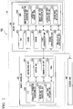
- FIG. 1 is a first diagram showing a functional configuration of an air conditioning system according to an embodiment of the present invention.
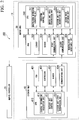
- FIG. 2 is a second diagram showing a functional configuration of an air conditioning system according to an embodiment of the invention.
- an air conditioning system 100 includes a remote controller 20, an indoor unit 30, and an outdoor unit 40.
- the remote controller 20 accepts the manipulation of the user and transmits the manipulation information according to the manipulation to the indoor unit 30.
- the indoor unit 30 is communicably connected to the remote controller 20 using a wireless communication technology such as infrared communication, executes various operations in accordance with the manipulation information transmitted from the remote controller 20, and outputs control information for controlling the operation of the outdoor unit 40.
- a wireless communication technology such as infrared communication
- the remote controller 20 and the indoor unit 30 may be communicably connected via a wired communication.
- the outdoor unit 40 is communicably connected to the indoor unit 30 by radio and executes various operations according to the control information transmitted from the indoor unit 30.
- the remote controller 20 includes a manipulation unit 201, a display unit 202, a communication unit 203, a timer 204, and a CPU 210.
- the manipulation unit 201 is an input device such as a button and a touch panel which accepts the manipulation from the user.
- the display unit 202 is a display device such as a liquid crystal display that displays various kinds of information, such as the operation state of the air conditioning system 1, and the temperature and humidity of the room in which the indoor unit 30 is provided.
- the display unit 202 sequentially updates the display contents in accordance with the manipulation performed by the user via the manipulation unit 201, and the states of the indoor unit 30 and the outdoor unit 40.
- the communication unit 203 transmits and receives various kinds of information to and from the indoor unit 30.
- the timer 204 measures the elapsed time after various processes and communications are performed in the remote controller 20.
- the CPU 210 has a manipulation information transmission unit 211, an indoor unit state acquisition unit 212, and a first mode switching unit 213.
- the manipulation information transmission unit 211 creates manipulation information on the basis of the manipulation performed by the user via the manipulation unit 201, and transmits the manipulation information to the indoor unit 30 via the communication unit 203.
- the manipulation information may include, for example, a starting instruction and a stopping instruction of the air conditioning system 100. Further, the manipulation information may include instructions such as temperature, air volume, and wind direction.
- the indoor unit state acquisition unit 212 periodically acquires the state of the indoor unit 30 (indoor unit state). Specifically, the indoor unit state acquisition unit 212 performs the transmission request of the indoor unit state to the indoor unit 30 via the communication unit 203 at each predetermined acquisition interval (for example, one minute), and acquires the indoor unit state included in the response from the indoor unit 30.
- the indoor unit state acquisition unit 212 performs the transmission request of the indoor unit state to the indoor unit 30 via the communication unit 203 at each predetermined acquisition interval (for example, one minute), and acquires the indoor unit state included in the response from the indoor unit 30.
- the first mode switching unit 213 switches the operation state of the first module 10 including the remote controller 20 and the indoor unit 30.
- FIG. 3 is a view showing the operation state of the first module according to the embodiment of the present invention.
- the operation state of the first module 10 is set to one of an 'operating mode,' a 'stop preparation mode,' and a 'standby mode.'
- the 'operating mode' represents a state in which both the remote controller 20 and the indoor unit 30 are started (state during operation).
- start manipulation the manipulation for starting the air conditioning system 100
- the first mode switching unit 213 sets the operation state of the first module 10 to the 'operating mode.
- the 'stop preparation mode' represents a state in which a process for stopping the operation of the indoor unit 30(stopping process) is being executed.
- the first mode switching unit 213 switches the operation state of the first module 10 to the 'stop preparation mode' when accepting a manipulation of stopping the air conditioning system 100 (stop manipulation) from the user at the time of the 'operating mode.
- the 'standby mode' represents a state in which the stopping process of the indoor unit 30 is completed, the operations of the remote controller 20 and the indoor unit 30 are stopped, and only the minimum necessary power (standby power) is supplied.
- the indoor unit state acquisition unit 212 acquires the indoor unit state indicating that the operation of the indoor unit 30 is stopped at the time of the 'stop preparation mode,' the first mode switching unit 213 switches the operation state of the first module 10 to the 'standby mode.
- the remote controller 20 and the indoor unit 30 are maintained in the normally communicable state.
- the operation state of the first module 10 is in the 'standby mode,' the communication between the remote controller 20 and the indoor unit 30 is cut off.
- the indoor unit 30 includes a fan 301, a louver 302, a sensor 303, a first communication unit 304, a second communication unit 305, a manipulation acceptance unit 306, and a CPU 310.
- the fan 301 takes in air in a room in which the indoor unit 30 is provided into the indoor unit 30 by rotating, and sends the air cooled or heated by a heat exchanger (not shown) to the room.
- the louver 302 changes the sending direction of the air sent to the room by the fan 301.
- the start and stop of the operation, and the operation amount of the fan 301 and the louver 302 are controlled via the actuators connected thereto.
- the sensor 303 is a device for measuring a state of a room in which the indoor unit 30 and the indoor unit 30 are provided, and includes at least one sensor for measuring the temperature of each part of the indoor unit 30, and the temperature and humidity of the room.
- the first communication unit 304 is a device for transmitting and accepting various kinds of information to and from the remote controller 20.
- the second communication unit 305 is a device for transmitting and accepting various kinds of information to and from the outdoor unit 40.
- a manipulation acceptance unit 306 is an input device such as a button and a touch panel which is provided in the main body of the indoor unit 30 to receive the manipulation from the user.
- the manipulation acceptance unit 306 creates manipulation information on the basis of the operation performed by the user via the manipulation acceptance unit 306, and outputs the manipulation information to the CPU 310.
- the manipulation information includes, for example, a starting instruction and a stopping instruction of the air conditioning system 100.
- the CPU 310 has a manipulation information acquisition unit 311, an operating control unit 312, an indoor unit state transmission unit 313, an outdoor unit state acquisition unit 314, and a second mode switching unit 315.
- the manipulation information acquisition unit 311 acquires the manipulation information accepted from the remote controller 20 via the first communication unit 304.
- the manipulation information acquisition unit 311 acquires the manipulation information from the manipulation acceptance unit 306.
- the operating control unit 312 controls the operations of the indoor unit 30 and the outdoor unit 40 on the basis of the manipulation information acquired by the manipulation information acquisition unit 311.
- the operating control unit 312 when the operating control unit 312 acquires the manipulation information including the stopping instruction, the operating control unit 312 starts the stopping process of the indoor unit 30, and transmits control information for requesting the stop of the operation to the outdoor unit 40. Further, when the operating control unit 312 acquires the manipulation information including the starting instruction, the operating control unit 312 operates each part of the indoor unit 30 to satisfy the setting (setting of cooling or heating, temperature setting, etc.) designated by the user, and transmits the control information for requesting the start of operation according to the setting to the outdoor unit 40.
- the setting setting of cooling or heating, temperature setting, etc.
- the indoor unit state transmission unit 313 When accepting the transmission request of the indoor unit state from the remote controller 20, the indoor unit state transmission unit 313 creates the indoor unit state according to the request and transmits the indoor unit state to the remote controller 20 via the first communication unit 304.
- the indoor unit state transmission unit 313 creates the indoor unit state on the basis of at least one of the operation states of the fan 301 and the louver 302 (the state indicating operation or stop, the operation amount of the actuator, etc.), and the states of the indoor unit 30 and the room (temperature, humidity, etc.) measured by the sensor 303.
- the outdoor unit state acquisition unit 314 periodically acquires the state of the outdoor unit 40 (outdoor unit state). Specifically, the outdoor unit state acquisition unit 314 performs the transmission request of the outdoor unit state to the outdoor unit 40 via the second communication unit 305 at each predetermined acquisition interval (for example, one minute), and acquires the outdoor unit state included in the response from the outdoor unit 40.
- the outdoor unit state acquisition unit 314 performs the transmission request of the outdoor unit state to the outdoor unit 40 via the second communication unit 305 at each predetermined acquisition interval (for example, one minute), and acquires the outdoor unit state included in the response from the outdoor unit 40.
- the second mode switching unit 315 switches the operation state of the second module 11 including the indoor unit 30 and the outdoor unit 40 on the basis of the manipulation information acquired by the manipulation information acquisition unit 311 and the outdoor unit state acquired by the outdoor unit state acquisition unit 314.
- FIG. 4 is a diagram showing the operation state of the second module according to the embodiment of the present invention.
- the operation state of the second module 11 is set to one of 'operating mode,' 'stop preparation mode,' and 'standby mode.
- the 'operating mode' represents a state in which both the indoor unit 30 and the outdoor unit 40 are started (a state in operation).
- the manipulation information acquisition unit 311 acquires the manipulation information including the starting instruction at the time of the 'stop preparation mode' or the 'standby mode
- the second mode switching unit 315 switches the operation state of the second module 11 to the 'operating mode.
- the 'stop preparation mode' represents a state in which a process for stopping the operation (stopping process) of the outdoor unit 40 is being executed.
- the manipulation information acquisition unit 311 acquires the manipulation information including the stopping instruction at the time of the 'operating mode
- the second mode switching unit 315 switches the operation state of the second module 11 to the 'stop preparation mode.
- the 'standby mode' represents a state in which the stopping process of the outdoor unit 40 is completed, the operation of the outdoor unit 40 is stopped, and only the minimum necessary power (standby power) is supplied.
- the outdoor unit state acquisition unit 314 acquires the outdoor unit state indicating that the operation of the outdoor unit 40 has stopped at the time of the 'stop preparation mode
- the second mode switching unit 315 switches the operation state of the second module 11 to the 'standby mode.
- the indoor unit 30 and the outdoor unit 40 are maintained in a normally communicable state.
- the operation state of the second module 11 is in the 'standby mode,' the communication between the indoor unit 30 and the outdoor unit 40 is cut off.
- the outdoor unit 40 has a fan 401, a compressor 402, a sensor 403, a communication unit 404, and a CPU 410.
- the fan 401 takes in the outdoor air into the outdoor unit 40 by rotating, and sends the air after the heat exchange by heat exchangers (not shown) of the indoor unit 30 and the outdoor unit 40 to the outside.
- the compressor 402 compresses the gas serving as a refrigerant to generate a high-temperature and high-pressure gas.
- the high-temperature and high-pressure gas generated by the compressor 402 is sent to the heat exchanger of the outdoor unit 40 or the heat exchanger of the indoor unit 30 on the basis of the control information from the indoor unit 30.
- the start and stop of the operation, and the operation amount of the fan 401 and the compressor 402 are controlled via the actuators and the engines connected thereto.
- the sensor 403 is a device for measuring the state of the outdoor unit 40 and outside thereof, and includes at least one sensor for measuring the temperature of each part of the outdoor unit 40, the gas pressure of the compressor 402, the temperature and humidity of the outside, and the like.
- the communication unit 404 is a device for transmitting and accepting various kinds of information to and from the indoor unit 30.
- the CPU 410 has a control information acquisition unit 411, an outdoor unit control unit 412, and an outdoor unit state transmission unit 413.
- the control information acquisition unit 411 acquires the control information accepted from the indoor unit 30 via the communication unit 404.
- the outdoor unit control unit 412 controls the operations (start and stop of operation, and operation amount) of each part of the outdoor unit 40 to satisfy the setting (setting of cooling operation or heating operation, temperature setting, and the like) designated by the user, on the basis of the control information acquired by the control information acquisition unit 411.
- the outdoor unit state transmission unit 413 When accepting the transmission request of the outdoor unit state from the indoor unit 30, the outdoor unit state transmission unit 413 creates the outdoor unit state response to the outdoor unit state, and transmits the outdoor unit state to the indoor unit 30 via the communication unit 404.
- the outdoor unit state transmission unit 413 creates the outdoor unit state, on the basis of at least one of the operation state of the fan 401 and the compressor 402 (a state indicating the operation or stop, the operation amount of the actuator and the engine, etc.) and the states (temperature, humidity, pressure, etc.) of the outdoor unit 40 and the outside measured by the sensor 403.
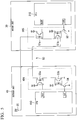
- FIG. 5 is a diagram showing a communication circuit which connects an indoor unit and an outdoor unit according to an embodiment of the present invention.
- the indoor unit 30, the second communication unit 305 and the communication unit 404 of the outdoor unit 40 are communicably connected via a communication line 50.
- Indoor unit side switches 51a and 51b and outdoor unit side switches 53a and 53b are connected in series to the communication line 50, and electric power is supplied from a constant voltage power supply 55.
- the indoor unit side switches 51a and 51b and the outdoor unit side switches 53a and 53b are photo couplers.
- an indoor unit side transistor 52 which is configured to switch the indoor unit side switch 51b to a conducting state or a non-conducting state is connected to the indoor unit side switch 51b.
- An outdoor unit side transistor 54 which is configured to switch the outdoor unit side switch 53b to the conducting state or the non-conducting state is connected to the outdoor unit side switch 53b.
- the indoor unit side switches 51a and 51b and the indoor unit side transistor 52 constitute the second communication unit 305 of the indoor unit 30.
- the outdoor unit side switches 53a and 53b and the outdoor unit side transistor 54 constitute a communication unit 404 in the outdoor unit 40.
- the second communication unit 305 of the indoor unit 30 controls ON (conduction) and OFF (non-conduction) of the indoor unit side transistor 52 to switch ON (conduction) and OFF (non-conduction) of the indoor unit side switch 51b.
- the outdoor unit side transistor 54 is maintained in the ON (conduction) state.
- a digital signal is generated by switching ON and OFF of the indoor unit side switch 51b, and the digital signal is transmitted to the outdoor unit side switch 53a via the communication line 50, and is input to a signal acceptance terminal Rx0 of the CPU 410.
- the control information is transmitted from the indoor unit 30 to the outdoor unit 40 as a digital signal.
- the communication unit 404 of the indoor unit 30 controls ON (conduction) and OFF (non-conduction) of the outdoor unit side transistor 54, and switches ON (conduction) and OFF (non-conduction) of the outdoor unit side switch 53b.
- the indoor unit side transistor 52 is maintained in the ON (conduction) state.
- a digital signal is generated by switching ON and OFF of the outdoor unit side switch 53b, and the digital signal is transmitted to the indoor unit side switch 51a via the communication line 50, and is input to a signal acceptance terminal Rx00 of the CPU 310.
- the control information is transmitted from the outdoor unit 40 to the indoor unit 30 as a digital signal.
- the second mode switching unit 315 When the operation state of the second module 11 is in the 'operating mode' or 'stop preparation mode,' the second mode switching unit 315 performs the instruction for permitting the communication with the outdoor unit 40 to the second communication unit 305. Then, when the control information is not transmitted from the indoor unit 30 side, the second communication unit 305 maintains the indoor unit side transistor 52 in the ON state in order to wait for the outdoor unit information transmitted from the outdoor unit 40. At this time, when the communication line 50 is closed by the indoor unit side transistor 52, electric power from the constant voltage power supply 55 is continuously supplied to the communication line 50.
- the second mode switching unit 315 of the indoor unit 30 performs instruction for stopping communication with the outdoor unit 40 to the second communication unit 305. Then, the second communication unit 305 switches the indoor unit side transistor 52 to OFF to cut off communication with the outdoor unit 40, while maintaining the outdoor unit side transistor 54 in the ON state. At this time, since the communication line 50 is opened by the indoor unit side transistor 52, electric power from the constant voltage power supply 55 does not flow through the communication line 50. Since the outdoor unit side transistor 54 is maintained in the ON state, the outdoor unit 40 can always receive the control information from the indoor unit 30.
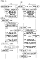
- FIG. 6 is a diagram showing a processing flow of the air conditioning system according to the embodiment of the present invention.
- the air conditioning system 100 according to the present embodiment simultaneously performs a process in the first module 10 including the remote controller 20 and the indoor unit 30, and a process in the second module 11 including the indoor unit 30 and the outdoor unit 40 in parallel.
- the indoor unit state acquisition unit 212 of the remote controller 20 transmits the transmission request of the indoor unit state to the indoor unit 30 at each predetermined acquisition interval (for example, one minute) (step S100).
- the indoor unit state transmission unit 313 of the indoor unit 30 When accepting the transmission request of the indoor unit state from the remote controller 20, the indoor unit state transmission unit 313 of the indoor unit 30 creates the indoor unit state according to the request, and transmits the indoor unit state to the remote controller 20 (step S101).
- the first mode switching unit 213 of the remote controller 20 switches the operation state of the first module 10 from 'operating mode' to 'stop preparation mode' (step S102).
- manipulation information transmission unit 211 of the remote controller 20 creates manipulation information including a stopping instruction on the basis of the manipulation of the user, and transmits the manipulation information to the indoor unit 30 (step S103).
- the operating control unit 312 of the indoor unit 30 starts the stopping process of the indoor unit 30 (step S104).
- step S105 the indoor unit state acquisition unit 212 of the remote controller 20 repeatedly executes a process (step S105) for performing the transmission request of the indoor unit state to the indoor unit 30 at each predetermined acquisition interval, similarly to the aforementioned process of step S100.
- the remote controller 20 monitors whether or not the stopping process of the indoor unit 30 is completed in the 'stop preparation mode.
- the indoor unit state transmission unit 313 of the indoor unit 30 transmits the indoor unit state indicating that the indoor unit 30 is in operation (step S106).
- the indoor unit state transmission unit 313 of the indoor unit 30 transmits the indoor unit state indicating that the indoor unit 30 is stopped (step S107).
- the indoor unit state transmission unit 313 of the indoor unit 30 may transmit the indoor unit state indicating that the indoor unit 30 is stopped, irrespective of whether or not a transmission request from the remote controller 20 is accepted.
- the first mode switching unit 213 changes the operation state of the first module 10 from the 'stop preparation mode' to the 'standby mode' (step S108).
- the first mode switching unit 213 performs a process of stopping the communication between the remote controller 20 and the indoor unit 30 (step S109).
- the first mode switching unit 213 instructs the indoor unit state acquisition unit 212 to stop the process of acquiring the indoor unit state (the process of making a transmission request).
- the indoor unit state acquisition unit 212 stops the process of regularly performing the transmission request of the indoor unit state until accepting a new instruction from the first mode switching unit 213.
- the indoor unit 30 maintains a state in which the manipulation information from the remote controller 20 and the transmission request for indoor unit state can always be accepted.
- the first mode switching unit 213 instructs the display unit 202 of the remote controller 20 to turn off the display.
- the remote controller 20 can reduce the electric power required for communication for acquiring the indoor unit state and the electric power required for displaying the display unit 202 .
- the outdoor unit state acquisition unit 314 of the indoor unit 30 performs the transmission request of the outdoor unit state to the outdoor unit 40 at each predetermined acquisition interval (for example, one minute) (step S200).
- the outdoor unit state transmission unit 413 of the outdoor unit 40 When accepting the transmission request of the outdoor unit state from the indoor unit 30, the outdoor unit state transmission unit 413 of the outdoor unit 40 creates an outdoor unit state according to the request and transmits the outdoor unit state to the indoor unit 30 (step S201).
- the indoor unit 30 and the outdoor unit 40 repeatedly execute the above-described processes of steps S200 to S201 when the operation state of the second module 11 is in the 'operating mode.
- the second mode switching unit 315 of the indoor unit 30 switches the operation state of the second module 11 from the 'operating mode' to the 'stop preparation mode' (step S202). Further, the operating control unit 312 of the indoor unit 30 transmits the control information for requesting the stop of the operation to the outdoor unit 40 (step S203).
- the outdoor unit control unit 412 of the outdoor unit 40 starts the stopping process of the outdoor unit 40 (step S204) when the control information acquisition unit 411 accepts the control information requesting the stop of the operation.
- the outdoor unit state acquisition unit 314 of the indoor unit 30 repeatedly executes a process (step S205) of performing a transmission request of the outdoor unit state to the outdoor unit 40 at each predetermined acquisition interval, similarly to the process of the above-described step S100.
- the indoor unit 30 monitors whether or not the stopping process of the outdoor unit 40 is completed in the 'stop preparation mode.
- the outdoor unit state transmission unit 413 of the outdoor unit 40 transmits an outdoor unit state indicating that the outdoor unit 40 is in operation when the stopping process of the outdoor unit 40 is being executed (step S206).
- the outdoor unit state transmission unit 413 transmits the outdoor unit state indicating that the outdoor unit 40 is stopped (step S207).
- the outdoor unit state transmission unit 413 of the outdoor unit 40 may transmit the outdoor unit state indicating that the outdoor unit 40 is stopped, regardless of whether or not the transmission request from the indoor unit 30 is accepted.
- the second mode switching unit 315 switches the operation state of the second module 11 from the 'stop preparation mode' to the 'standby mode' (step S208).
- the second mode switching unit 315 performs the process of stopping the communication between the indoor unit 30 and the outdoor unit 40 (step S209).
- the second mode switching unit 315 instructs the outdoor unit state acquisition unit 314 to stop the process of acquiring the outdoor unit state (the process of making a transmission request).
- the outdoor unit state acquisition unit 314 stops the process of regularly performing the transmission request of the outdoor unit state until a new instruction from the second mode switching unit 315 is received.
- the second mode switching unit 315 instructs the second communication unit 305 to stop the communication with the outdoor unit 40.
- the second communication unit 305 switches the indoor unit side transistor 52 to the OFF state to cut off the communication with the outdoor unit 40, while maintaining the outdoor unit side transistor 54 in the ON state.
- the communication line 50 is opened by the indoor unit side transistor 52, the electric power from the constant voltage power supply 55 does not flow through the communication line 50.
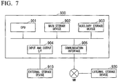
- FIG. 7 is a diagram showing hardware configuration of a remote controller, an indoor unit, and an outdoor unit according to an embodiment of the present invention.
- the computer 900 includes a CPU 901, a main storage device 902, an auxiliary storage device 903, an input and output interface 904, and a communication interface 905.
- the remote controller 20, the indoor unit 30, and the outdoor unit 40 are mounted on different computers 900, respectively.
- the operations of the respective parts of the remote controller 20, the indoor unit 30, and the outdoor unit 40 are stored in the auxiliary storage device 903 of each computer 900 in the form of a program.
- the CPU 901 (the CPU 210, the CPU 310, and the CPU 410) reads the program from the auxiliary storage device 903, develops the program in the main storage device 902, and executes the aforementioned processes in accordance with the program.
- the CPU 901 secures a storage area for storing various kinds of information acquired and generated through the processes in the main storage device 902. Further, the CPU 901 secures a storage area for storing data under process in the auxiliary storage device 903 in accordance with the program.
- the computer 900 is connected to the external storage device 910 via the input and output interface 904, and the storage area may be reserved in the external storage device 910. Further, the computer 900 is connected to the external storage device 920 via the communication interface 905, and the storage area may be secured in the external storage device 920.
- the auxiliary storage device 903 is an example of a non-transitory tangible medium.
- Other examples of non-transitory tangible media include magnetic disks, magneto-optical disks, CD-ROMs, DVD-ROMs, semiconductor memories, and the like connected via the input and output interface 904.
- the distributed computer 900 may develop the program in the main storage device 902 and execute the aforementioned processes.
- the program may achieve a part of the above-described functions.
- the program may be a so-called differential file (differential program) that achieves the above-described function by a combination with another program already stored in the auxiliary storage device 903.
- the air conditioning system 100 includes the indoor unit 30, and the remote controller 20 communicably connected to the indoor unit 30.
- the remote controller 20 has a manipulation information transmission unit 211 that transmits manipulation information including a starting instruction and a stopping instruction of the indoor unit 30 to the indoor unit 30 on the basis of the manipulation of the user, an indoor unit state acquisition unit 212 which is configured to periodically acquire the indoor unit state, and a first mode switching unit 213 which is configured to switch the operation state of the first module 10 including the indoor unit 30 and the remote controller 20 on the basis of the manipulation information and the indoor unit state.
- the first mode switching unit 213 switches the operation state of the first module 10 to the 'stop preparation mode' for executing the stopping process of the indoor unit. Further, when the operation state of the first module 10 is in the 'stop preparation mode' and the indoor unit 30 is determined to be in the stopped state on the basis of the indoor unit state, the first mode switching unit 213 switches the operation state of the first module 10 to the 'standby mode' for stopping the communication between the indoor unit 30 and the remote controller 20.
- the first mode switching unit 213 of the remote controller 20 stops the communication between the remote controller 20 and the indoor unit 30. In this way, it is possible to reduce the electric power for maintaining the remote controller 20 and the indoor unit 30 in a communicable state during the 'standby mode.
- the first mode switching unit 213 instructs the display unit 202 of the remote controller 20 to turn off the display.
- the remote controller 20 can reduce electric power required for displaying the display unit 202.
- the indoor unit state acquisition unit 212 stops acquisition of the indoor unit state.
- the indoor unit state acquisition unit 212 stops the process of periodically performing transmission request of the indoor unit state until accepting a new instruction from the first mode switching unit 213.
- the remote controller 20 can reduce the electric power required for communication for acquiring the indoor unit state.
- the air conditioning system 100 further includes an outdoor unit 40 that is communicably connected to the indoor unit 30.
- the indoor unit 30 has a manipulation information acquisition unit 311 that acquires the manipulation information, an outdoor unit state acquisition unit 314 that periodically acquires the outdoor unit state, and a second mode switching unit 315 which is configured to switch the operation state of the second module 11 including the indoor unit 30 and the outdoor unit 40 on the basis of the manipulation information and the outdoor unit state.
- the second mode switching unit 315 switches the operation state of the second module 11 to the 'stop preparation mode' for executing the stopping process of the outdoor unit 40.
- the second mode switching unit 315 switches the operation state of the second module 11 to the 'standby mode' in which the communication between the indoor unit 30 and the outdoor unit 40 is stopped.
- the air conditioning system 100 can further reduce the electric power for maintaining the indoor unit 30 and the outdoor unit 40 in the communicable state.
- the air conditioning system 100 separately performs a process of switching the operation state of the first module 10 including the remote controller 20 and the indoor unit 30, and a process of switching the operation state of the second module 11 including the indoor unit 30 and the outdoor unit 40 in parallel.
- the outdoor unit state acquisition unit 314 stops acquisition of the outdoor unit state.
- the outdoor unit state acquisition unit 314 stops the process of regularly performing the transmission request of the outdoor unit state until accepting a new instruction from the second mode switching unit 315.
- the indoor unit 30 can reduce the electric power required for communication for acquiring the outdoor unit state.
- the air conditioning system 100 includes an indoor unit 30, and an outdoor unit 40 that is communicably connected to the indoor unit 30 via the communication line 50.
- An indoor unit side switch 51b and an outdoor unit side switch 53b are connected in series to the communication line 50.
- the indoor unit 30 has a manipulation information acquisition unit 311 that acquires manipulation information including an starting instruction and a stopping instruction of the indoor unit 30 which are input on the basis of the user's manipulation, an outdoor unit state acquisition unit 314 that periodically acquires the outdoor unit state, and a second mode switching unit 315 which is configured to switch the conduction state of the indoor unit side switch 51b and the outdoor unit side switch 53b on the basis of the manipulation information and the outdoor unit state.
- a manipulation information acquisition unit 311 that acquires manipulation information including an starting instruction and a stopping instruction of the indoor unit 30 which are input on the basis of the user's manipulation
- an outdoor unit state acquisition unit 314 that periodically acquires the outdoor unit state
- a second mode switching unit 315 which is configured to switch the conduction state of the indoor unit side switch 51b and the outdoor unit side switch 53b on the basis of the manipulation information and the outdoor unit state.
- the second mode switching unit 315 maintains the conduction state of the outdoor unit side switch 53b and switches the indoor unit side switch 51b to the non-conduction state.
- the communication line for connecting the indoor unit and the outdoor unit has been always maintained in the conduction state. That is, even when the air conditioning system is stopped, electric power is always supplied to the communication line, which is one cause of increasing the standby power.
- the second mode switching unit 315 of the indoor unit 30 switches the indoor unit side switch 51b to the non-conduction state, while maintaining the conduction state of the outdoor unit side switch 53b. In this way, since the communication line 50 is opened during the 'standby mode,' the electric power does not flow through the communication line 50, and the standby power can be reduced.
- FIG. 8 is a diagram showing a process flow of an air conditioning system according to a modified example of the present invention.
- the indoor unit state acquisition unit 212 of the remote controller 20 stops the process of acquiring the indoor unit state at each predetermined acquisition interval (for example, one minute) has been described.
- the indoor unit 30 and the outdoor unit 40 are started by accepting the starting operation, but the remote controller 20 cannot know that the indoor unit 30 is started.
- the remote controller 20 can recognize the state of the indoor unit 30.
- the indoor unit state acquisition unit 212 of the remote controller 20 performs the transmission request of the indoor unit state to the indoor unit 30 (step S110). Further, the predetermined checking interval t is set to the time (for example, 1 hour) longer than the acquisition interval (one minute) in the 'operating mode' and the 'stop preparation mode.
- the indoor unit 30 maintains a state in which the manipulation information from the remote controller 20 and the transmission request of the indoor unit state can always be accepted. Therefore, the indoor unit state transmission unit 313 of the indoor unit 30 accepts the transmission request of the remote controller 20 and transmits the indoor unit state (step S111). In the example of FIG. 8 , the starting operation of the user is not accepted at this point, and the indoor unit 30 also maintains the stopped state. Therefore, in step S111, the indoor unit state transmission unit 313 transmits the indoor unit state indicating that the indoor unit 30 is in the stopped state.
- the second mode switching unit 315 of the indoor unit 30 switches the operation state of the second module 11 to the 'operating mode' (step S210).
- the operating control unit 312 of the indoor unit 30 performs a process of operating each part of the indoor unit 30 (step S211), and transmits control information which requests the start of operation to the outdoor unit 40 (step S212).
- the outdoor unit control unit 412 controls (starts) the operation of each part of the outdoor unit 40 on the basis of the control information (step S213).
- the indoor unit 30 and the outdoor unit 40 repeatedly execute a transmission request of the outdoor unit state (step S214) and a transmission of the outdoor unit state (step S215) at each predetermined acquisition interval (for example, one minute). This operation is the same as in the aforementioned embodiment.
- the operation state of the first module 10 is maintained in the 'standby mode,' and the remote controller 20 does not recognize that the indoor unit 30 is in operation.
- the indoor unit state acquisition unit 212 of the remote controller 20 performs the transmission request of the indoor unit state to the indoor unit 30 again (step S112).
- the indoor unit state transmission unit 313 of the indoor unit 30 accepts the transmission request of the remote controller 20 and transmits the indoor unit state (step S113).
- the indoor unit state transmission unit 313 transmits the indoor unit state indicating that the indoor unit 30 is in operation.
- the first mode switching unit 213 of the remote controller 20 switches the operation state of the first module 10 from the 'standby mode' to the 'operating mode' (step S114).
- the first mode switching unit 213 of the remote controller 20 can make the operation state of the first module 10 and the operation state of the second module 11 match each other.
- the standby power can be reduced.
Landscapes
- Engineering & Computer Science (AREA)
- Chemical & Material Sciences (AREA)
- Combustion & Propulsion (AREA)
- Mechanical Engineering (AREA)
- General Engineering & Computer Science (AREA)
- Signal Processing (AREA)
- Physics & Mathematics (AREA)
- Fuzzy Systems (AREA)
- Mathematical Physics (AREA)
- Human Computer Interaction (AREA)
- Air Conditioning Control Device (AREA)
Applications Claiming Priority (1)
| Application Number | Priority Date | Filing Date | Title |
|---|---|---|---|
| JP2017059157A JP2018162902A (ja) | 2017-03-24 | 2017-03-24 | 空気調和システム及び制御方法 |
Publications (2)
| Publication Number | Publication Date |
|---|---|
| EP3379162A2 true EP3379162A2 (de) | 2018-09-26 |
| EP3379162A3 EP3379162A3 (de) | 2018-11-21 |
Family
ID=61731629
Family Applications (1)
| Application Number | Title | Priority Date | Filing Date |
|---|---|---|---|
| EP18162939.5A Withdrawn EP3379162A3 (de) | 2017-03-24 | 2018-03-20 | Klimaanlagensystem und steuerungsverfahren |
Country Status (2)
| Country | Link |
|---|---|
| EP (1) | EP3379162A3 (de) |
| JP (1) | JP2018162902A (de) |
Citations (1)
| Publication number | Priority date | Publication date | Assignee | Title |
|---|---|---|---|---|
| JP2000097484A (ja) | 1998-09-22 | 2000-04-04 | Hitachi Ltd | 空気調和機 |
Family Cites Families (7)
| Publication number | Priority date | Publication date | Assignee | Title |
|---|---|---|---|---|
| JP4529603B2 (ja) * | 2004-09-14 | 2010-08-25 | ダイキン工業株式会社 | セパレート型空気調和機 |
| JP5241585B2 (ja) * | 2009-04-06 | 2013-07-17 | 三菱電機株式会社 | 空気調和機 |
| JP2012107817A (ja) * | 2010-11-18 | 2012-06-07 | Hitachi Appliances Inc | 空気調和機 |
| JP5168365B2 (ja) * | 2011-01-20 | 2013-03-21 | 株式会社富士通ゼネラル | 空気調和機 |
| KR101858938B1 (ko) * | 2011-09-19 | 2018-06-29 | 삼성전자주식회사 | 공기 조화기 |
| JP2013137114A (ja) * | 2011-12-28 | 2013-07-11 | Daikin Industries Ltd | 空気調和装置 |
| AU2012359736B2 (en) * | 2011-12-28 | 2014-11-13 | Daikin Industries, Ltd. | Air conditioner |
-
2017
- 2017-03-24 JP JP2017059157A patent/JP2018162902A/ja active Pending
-
2018
- 2018-03-20 EP EP18162939.5A patent/EP3379162A3/de not_active Withdrawn
Patent Citations (1)
| Publication number | Priority date | Publication date | Assignee | Title |
|---|---|---|---|---|
| JP2000097484A (ja) | 1998-09-22 | 2000-04-04 | Hitachi Ltd | 空気調和機 |
Also Published As
| Publication number | Publication date |
|---|---|
| JP2018162902A (ja) | 2018-10-18 |
| EP3379162A3 (de) | 2018-11-21 |
Similar Documents
| Publication | Publication Date | Title |
|---|---|---|
| US10544946B2 (en) | Intelligent HVAC control including automatic furnace shutdown event processing | |
| CN111422023B (zh) | 车辆的空调控制系统及方法、非暂时性计算机可读介质 | |
| CN101517326B (zh) | 空调控制的中间装置、空调控制系统、空调控制方法以及空调控制程序 | |
| US11368328B2 (en) | Method for controlling terminal apparatus that remotely controls air conditioner, non-transitory recording medium storing program executed by terminal apparatus, recommend method executed by terminal apparatus, and terminal apparatus | |
| US9702581B2 (en) | Air conditioning system | |
| EP2604933A1 (de) | Heizungs-, Belüftungs- und Klimaanlagensystem-Benutzerschnittstelle mit einer One-Touch-Funktion und Betriebsverfahren dafür | |
| US20150362206A1 (en) | System and method to manage energy consumption in an hvac system | |
| JP5335043B2 (ja) | 設備機器制御装置及び設備機器システム | |
| CN107676938B (zh) | 空调器控制方法、装置、电子设备及计算机可读存储介质 | |
| US8376242B1 (en) | Wireless user interface for an HVAC controller and method of operating the same | |
| EP3712528B1 (de) | Steuerungssystem, installationsgerät, fernsteuerung, steuerverfahren und programm | |
| US9920949B2 (en) | Air conditioning system and energy management method of air conditioning system | |
| EP3379162A2 (de) | Klimaanlagensystem und steuerungsverfahren | |
| CN108954716B (zh) | 空调器的控制方法、空调器和计算机可读存储介质 | |
| CN104654521A (zh) | 一种功能启动方法和移动电子设备 | |
| CN205245452U (zh) | 基于调温器的变频空调控制装置、终端及系统 | |
| US20250109874A1 (en) | Universal connector for air conditioning controller | |
| CN114047709B (zh) | 设备控制方法、装置、智能手表、芯片及存储介质 | |
| JP7325653B2 (ja) | 空気調和システム | |
| JP2021042877A (ja) | サーバおよび制御システム、並びに制御プログラム | |
| US20190360713A1 (en) | System and method for hvac system schedule generation based on user defined comfort level inputs | |
| CN118189277A (zh) | 采暖设备的级联控制方法、设备、存储介质及程序产品 | |
| WO2018216202A1 (ja) | 空調管理制御装置、携帯端末、および空調機制御方法 | |
| US11339986B2 (en) | Remote controller and air-conditioning apparatus | |
| US20050221860A1 (en) | Electronic device |
Legal Events
| Date | Code | Title | Description |
|---|---|---|---|
| PUAI | Public reference made under article 153(3) epc to a published international application that has entered the european phase |
Free format text: ORIGINAL CODE: 0009012 |
|
| STAA | Information on the status of an ep patent application or granted ep patent |
Free format text: STATUS: THE APPLICATION HAS BEEN PUBLISHED |
|
| AK | Designated contracting states |
Kind code of ref document: A2 Designated state(s): AL AT BE BG CH CY CZ DE DK EE ES FI FR GB GR HR HU IE IS IT LI LT LU LV MC MK MT NL NO PL PT RO RS SE SI SK SM TR |
|
| AX | Request for extension of the european patent |
Extension state: BA ME |
|
| PUAL | Search report despatched |
Free format text: ORIGINAL CODE: 0009013 |
|
| AK | Designated contracting states |
Kind code of ref document: A3 Designated state(s): AL AT BE BG CH CY CZ DE DK EE ES FI FR GB GR HR HU IE IS IT LI LT LU LV MC MK MT NL NO PL PT RO RS SE SI SK SM TR |
|
| AX | Request for extension of the european patent |
Extension state: BA ME |
|
| RIC1 | Information provided on ipc code assigned before grant |
Ipc: F24F 11/88 20180101ALI20181012BHEP Ipc: F24F 11/56 20180101ALI20181012BHEP Ipc: F24F 11/46 20180101ALI20181012BHEP Ipc: F24F 11/65 20180101AFI20181012BHEP |
|
| STAA | Information on the status of an ep patent application or granted ep patent |
Free format text: STATUS: REQUEST FOR EXAMINATION WAS MADE |
|
| 17P | Request for examination filed |
Effective date: 20190520 |
|
| RBV | Designated contracting states (corrected) |
Designated state(s): AL AT BE BG CH CY CZ DE DK EE ES FI FR GB GR HR HU IE IS IT LI LT LU LV MC MK MT NL NO PL PT RO RS SE SI SK SM TR |
|
| GRAP | Despatch of communication of intention to grant a patent |
Free format text: ORIGINAL CODE: EPIDOSNIGR1 |
|
| STAA | Information on the status of an ep patent application or granted ep patent |
Free format text: STATUS: GRANT OF PATENT IS INTENDED |
|
| RIC1 | Information provided on ipc code assigned before grant |
Ipc: F24F 11/56 20180101ALI20190723BHEP Ipc: F24F 11/65 20180101AFI20190723BHEP Ipc: F24F 11/46 20180101ALI20190723BHEP Ipc: F24F 11/88 20180101ALI20190723BHEP |
|
| INTG | Intention to grant announced |
Effective date: 20190826 |
|
| STAA | Information on the status of an ep patent application or granted ep patent |
Free format text: STATUS: THE APPLICATION IS DEEMED TO BE WITHDRAWN |
|
| 18D | Application deemed to be withdrawn |
Effective date: 20200108 |