EP3379193A1 - Umgebautes magazin für eine zu übungs- oder trainingszwecken umgerüstete schusswaffe und umgerüstete schusswaffe mit einem solchen umgebauten magazin - Google Patents
Umgebautes magazin für eine zu übungs- oder trainingszwecken umgerüstete schusswaffe und umgerüstete schusswaffe mit einem solchen umgebauten magazin Download PDFInfo
- Publication number
- EP3379193A1 EP3379193A1 EP18163114.4A EP18163114A EP3379193A1 EP 3379193 A1 EP3379193 A1 EP 3379193A1 EP 18163114 A EP18163114 A EP 18163114A EP 3379193 A1 EP3379193 A1 EP 3379193A1
- Authority
- EP
- European Patent Office
- Prior art keywords
- magazine
- compressed gas
- valve
- firearm
- pressure accumulator
- Prior art date
- Legal status (The legal status is an assumption and is not a legal conclusion. Google has not performed a legal analysis and makes no representation as to the accuracy of the status listed.)
- Granted
Links
Images



Classifications
-
- F—MECHANICAL ENGINEERING; LIGHTING; HEATING; WEAPONS; BLASTING
- F41—WEAPONS
- F41A—FUNCTIONAL FEATURES OR DETAILS COMMON TO BOTH SMALLARMS AND ORDNANCE, e.g. CANNONS; MOUNTINGS FOR SMALLARMS OR ORDNANCE
- F41A33/00—Adaptations for training; Gun simulators
- F41A33/06—Recoil simulators
-
- F—MECHANICAL ENGINEERING; LIGHTING; HEATING; WEAPONS; BLASTING
- F41—WEAPONS
- F41B—WEAPONS FOR PROJECTING MISSILES WITHOUT USE OF EXPLOSIVE OR COMBUSTIBLE PROPELLANT CHARGE; WEAPONS NOT OTHERWISE PROVIDED FOR
- F41B11/00—Compressed-gas guns, e.g. air guns; Steam guns
- F41B11/60—Compressed-gas guns, e.g. air guns; Steam guns characterised by the supply of compressed gas
- F41B11/62—Compressed-gas guns, e.g. air guns; Steam guns characterised by the supply of compressed gas with pressure supplied by a gas cartridge
-
- F—MECHANICAL ENGINEERING; LIGHTING; HEATING; WEAPONS; BLASTING
- F41—WEAPONS
- F41B—WEAPONS FOR PROJECTING MISSILES WITHOUT USE OF EXPLOSIVE OR COMBUSTIBLE PROPELLANT CHARGE; WEAPONS NOT OTHERWISE PROVIDED FOR
- F41B11/00—Compressed-gas guns, e.g. air guns; Steam guns
- F41B11/70—Details not provided for in F41B11/50 or F41B11/60
- F41B11/72—Valves; Arrangement of valves
-
- F—MECHANICAL ENGINEERING; LIGHTING; HEATING; WEAPONS; BLASTING
- F41—WEAPONS
- F41B—WEAPONS FOR PROJECTING MISSILES WITHOUT USE OF EXPLOSIVE OR COMBUSTIBLE PROPELLANT CHARGE; WEAPONS NOT OTHERWISE PROVIDED FOR
- F41B11/00—Compressed-gas guns, e.g. air guns; Steam guns
- F41B11/70—Details not provided for in F41B11/50 or F41B11/60
- F41B11/73—Sealing arrangements; Pistons
-
- F—MECHANICAL ENGINEERING; LIGHTING; HEATING; WEAPONS; BLASTING
- F41—WEAPONS
- F41B—WEAPONS FOR PROJECTING MISSILES WITHOUT USE OF EXPLOSIVE OR COMBUSTIBLE PROPELLANT CHARGE; WEAPONS NOT OTHERWISE PROVIDED FOR
- F41B11/00—Compressed-gas guns, e.g. air guns; Steam guns
- F41B11/50—Magazines for compressed-gas guns; Arrangements for feeding or loading projectiles from magazines
- F41B11/55—Magazines for compressed-gas guns; Arrangements for feeding or loading projectiles from magazines the projectiles being stored in stacked order in a removable box magazine, rack or tubular magazine
- F41B11/56—Magazines for compressed-gas guns; Arrangements for feeding or loading projectiles from magazines the projectiles being stored in stacked order in a removable box magazine, rack or tubular magazine the magazine also housing a gas cartridge
Definitions
- the present invention relates to a rebuilt magazine for insertion into a magazine receptacle of a firearm which has been converted for practice or training purposes and which has a pneumatic device for simulating a recoil of the firearm upon actuation of a trigger of the firearm and the rebuilt magazine.
- the magazine has a pneumatic pressure accumulator, in which a compressed gas for actuating the pneumatic device of the Firearm is stored, and a filling opening, which is provided for filling the pneumatic pressure accumulator with compressed gas from a compressed gas source, with a check valve.
- the check valve is designed to close the accumulator gas-tight in its shut-off position, if no compressed gas from the compressed gas source is applied to the filling opening to prevent leakage of the stored pressure gas in the pressure accumulator.
- the invention also relates to a firearm which has been converted for practice or training purposes and which comprises a pneumatic device for simulating a recoil of the firearm upon actuation of a trigger of the firearm and a rebuilt magazine with a pneumatic pressure accumulator in which a compressed gas for actuating the pneumatic Device of the firearm is stored.
- weapon simulators which simulate the firing of weapons.
- This firearms are used, which have been converted for practice purposes.
- the weapon simulators are mainly used in the military environment. From the US 4,302,190
- a rifle recoil simulator is known in which compressed air passes through openings in the gun barrel to move the rifle barrel upward in a simulated recoil motion.
- a switch on the trigger activates an electromagnetic pneumatic valve to control the flow of air to the openings in the gun barrel.
- the recoil is not simulated by a reciprocating shutter, but solely by a controlled air flow.
- a converted firearm for a weapon simulator in which a reciprocable closure is pneumatically triggered by compressed air when the trigger is actuated.
- the converted firearm usually does not shoot any ammunition, it lacks a firing triggered by the firing of the ammunition and a consequent back-and-forth motion of the shutter.
- the recoil can be simulated by the well-known converted firearm.
- a pneumatic pressure accumulator contain, from which air can escape via electromagnetically actuated pneumatic valves when pressing the trigger and can be used for reciprocating movement of the closure.
- Hand-held weapons adapted for training purposes are known in which the pneumatic pressure accumulator, in which compressed gas is stored for actuating the device for simulating a recoil of the weapon in the event of firing a shot, is part of a rebuilt magazine.
- the rebuilt magazine is very similar to a real magazine containing cartridges to be fired from a real firearm.
- the converted magazine can be inserted into a magazine receptacle in the handle portion of a converted firearm and releasably secured therein.
- the accumulator includes a certain amount of pressurized gas, so that with the rebuilt firearm a certain number of shots can be delivered. With each fired shot, a portion of the compressed gas stored in the pressure accumulator is discharged into the recoil simulation apparatus. When the maximum possible number of shots is reached, the accumulator must be recharged, which can be done with a trained loader.
- the rebuilt magazine with the pneumatic accumulator has an outlet opening over which the in the Magazine receptacle in the handle portion of the converted firearm inserted magazine or the pneumatic accumulator contained therein is connected to the device for simulating a recoil of the firearm.
- the outlet opening of the rebuilt magazine is associated with a check valve which automatically closes the outlet opening as soon as the magazine is removed from the magazine receptacle and releases the outlet opening as soon as the magazine is fully inserted into the magazine receptacle.
- the rebuilt magazine has a filling opening, via which the pneumatic pressure accumulator can be filled with compressed gas.
- the filling opening of the rebuilt magazine is associated with a check valve, which automatically closes the filling opening when the magazine no longer has a connection to a compressed gas connection of a compressed gas source or no more compressed gas for charging the pressure accumulator, and the filling opening releases as soon as the magazine to a compressed gas connection Pressure gas source is connected and compressed gas flows to charge the pressure accumulator.
- the check valves of the known converted magazines are usually constructed in a conventional manner, that is they have a valve body, for example. In the form of a ball which is pressed by means of a spring element against a valve seat.
- designed check valves are only for relatively low Suitable pressures, for example, about 11 bar when using butane as the pressurized gas or about 57 bar when using carbon dioxide as a pressurized gas.
- compressed or compressed air should be able to be used as compressed gas, which bears against the check valve at pressures in the range from 250 to 300 bar.
- the magazine forms no flat surface in the region of the filling opening and the check valve. Rather, the filling opening is always formed clearly visible, so that when using the gun provided with the known gun dirt and moisture can be deposited in the filling opening, which then a filling of the pneumatic accumulator of the magazine is affected by compressed gas, since a gas-tight connection between a Pressure gas source of a charging device and the accumulator of the magazine then under certain circumstances can no longer be produced.
- the present invention therefore based on the object to design the known magazine and further, that it can be filled via the filling opening with compressed gas at very high pressures in the range of about 250 to 300, that the Filling opening is protected against contamination and damage from the outside and that, if possible, can also be directly and clearly recognized from the outside without additional aids, whether the accumulator of the magazine is depressurized or not.
- a rebuilt magazine with the features of claim 1 is proposed.
- the check valve has a valve in a bore parallel to the flow direction of the pressurized gas through the filling opening movable valve piston having at its distal end a directed to the outside of the magazine outer surface and is formed such that the Outer surface of the valve piston in the shut-off position of the check valve is flush with the outside of the magazine.
- the valve piston forms the closure part of the check valve. It is deliberately designed as a piston with an outer surface facing the outside of the magazine at a distal end of the piston. This outer surface of the valve piston closes in the shut-off position of the check valve flush with the outside of the magazine around the filling opening around, so that a flat Outside of the magazine also in the region of the filling opening results. Ingress of dirt and / or moisture into the filling opening is effectively prevented.
- a gas-tight connection between a compressed gas source of a charging device for filling the pneumatic pressure accumulator of the magazine with compressed gas and the pressure accumulator of the magazine can be produced with higher reliability and reliability.
- an outlet opening of the charging device can be gas-tightly connected to the filling opening of the magazine or the accumulator without problems due to contamination or moisture to fill the pressure accumulator with compressed gas.
- the design of the closure part of the check valve as a valve piston results in a much more stable and robust design of the check valve, so that it can withstand even very high pressures in the range of 250 to 300 bar without problems, as they can, for example, when using pressure or compressed air when filling the pressure accumulator with compressed gas and in the pressure accumulator itself occur.
- the outer surface formed at the distal end of the valve piston serves to indicate whether pressurized gas is still under pressure in the pneumatic accumulator of the magazine or not. This is especially true when alone the voltage applied from the outside of the valve piston pressure of the compressed gas from the Pressure gas source and the pressure applied from the inside to the valve piston of the pressure gas stored in the pressure accumulator cause a movement of the valve piston parallel to the flow direction of the compressed gas through the filling opening and the check valve has no additional spring elements. In this case, the outer surface of the valve piston is flush with the outer surface of the magazine as long as the pneumatic accumulator is under pressure.
- valve piston Only when the pressure accumulator is depressurized, no force acts on the valve piston, which could press this outwardly into the shut-off position, and the valve piston falls into a retracted rest position in which the outer surface of the valve piston dips into the filling. This can be clearly seen from outside the magazine without any additional aids. In this case, the valve piston either due to gravity or supported by an additional spring element can reach the rest position as soon as the pressure applied in the pressure accumulator has fallen below a certain low pressure value. As a result, the safety in handling the magazine, in particular with regard to maintenance and repair, can be significantly improved.
- FIG. 1 is a retrofitted for practice purposes firearm as part of a weapon simulator in its entirety by the reference numeral 1 denotes.
- the weapon simulator (not shown) is used to train as realistic as possible using rebuilt firearms, such as the firearm 1.
- the weapon simulator can be a central control computer in which all firearms used in the vicinity of the weapon simulator, such as the firearm 1 and other converted firearms, are registered or registered.
- the control computer communicates with the registered firearms in a communication connection, which can be realized via an electrical line or wirelessly, for example by radio.
- the control computer serves for the coordination and evaluation of training units of the individual registered firearms.
- On a central control computer of the weapon simulator can also be dispensed with if, for example, the converted firearm 1 is used for recreational purposes.
- the firearm 1 is similar in appearance and weight, as well as in its feel and operability from a real firearm.
- the firearm 1, however, has been converted so that it does not shoot blank cartridges or real ammunition.
- the various actions that take place in a real firearm before, during and after a delivery of a shot and cause a recoil of the weapon must therefore be simulated in the converted firearm 1.
- the firearm 1 has a pneumatically operated by means of compressed gas device for simulating a recoil when "firing" a simulated shot.
- sensors can be arranged, which detect a current operating state of the firearm 1, and it can be provided actuators that make depending on the current operating state corresponding actions, so that the most realistic possible use of the firearm 1 is given.
- a sensor 2 ' may detect the actuation of a trigger or trigger 2, resulting in the "firing" of a simulated shot, possibly after further conditions are met.
- an electronic control unit 17 can be activated and thus a laser 36 can be activated in order to emit a laser beam in the target direction out of the barrel 38 of the weapon 1.
- the sensor 2 'and the control electronics 17 are shown only schematically; those skilled in the art know how to connect and switch to each other so that the laser 36 is activated at the time the trigger 2 is actuated.
- a recoil of the firearm 1 is simulated.
- the movement of the closure 3 can be triggered, for example, by means of a shooting cylinder / piston arrangement 9.
- a further sensor (not shown) may be provided.
- a hydraulic medium for example a gas, in particular air, is used to actuate the closure 3, which, if necessary, the closure 3 and the shooting cylinder / piston assembly 9 applied.
- a housing of the firearm 1 is denoted by the reference numeral 4.
- the housing 4 comprises a handle 10, which has an opening 11 at its lower end side, behind which hides a magazine holder formed in the interior of the handle 10.
- a magazine with one or more cartridges contained therein is inserted and releasably secured in the magazine receptacle.
- a converted magazine 12 is inserted and fixed in the magazine receptacle.
- a further sensor may be provided in order to detect a magazine 12 which has been inserted and fixed properly in the magazine receptacle.
- the rebuilt magazine 12 resembles a real magazine in terms of its appearance and weight, as well as its feel and usability.
- the rebuilt magazine 12 comprises in its interior a pneumatic pressure accumulator 13, in which a compressed gas, for example air, is stored under high pressure, for example in the range from 200 to 300 bar.
- a compressed gas for example air
- the stored in the pressure accumulator 13 compressed gas is used to actuate the shutter 3 when "firing" a "shot” with the firearm 1 to simulate a recoil of the weapon 1.
- the shutter 3 Upon actuation of the trigger 2, the shutter 3 by compressed gas from the pressure accumulator 13 out and reciprocated. It is conceivable that only the rearwardly directed forward movement of the closure 3 is generated by the compressed gas, whereas the forwardly directed movement in another way, for example.
- the shutter 3 return element eg a compression spring
- the pressure accumulator 13 of the rebuilt magazine 12 communicates via a line 20 with an outlet opening 22, which is associated with a check valve 24 which closes the outlet opening 22 when the magazine 12 is not fully inserted into the magazine holder.
- the firearm 1 has at the foot of the magazine receptacle on a connecting piece 26 which protrudes with inserted magazine 12 in the outlet opening 22 and the check valve 24 opens automatically, so that the compressed gas from the pressure accumulator 13 is applied to the pneumatic device for the simulation of the recoil of the firearm 1 ,
- the flow of compressed gas in the device for the simulation of the recoil can be controlled, so that the compressed gas, for example.
- the connecting piece 26 is provided on its outer peripheral surface with sealing rings 28, through which the connecting piece 26 is sealed against the inner wall of the outlet opening 22.
- an inlet opening 30 is formed, on the fully inserted into the magazine holder magazine 12, the compressed gas from the pressure accumulator 13 via the line 20, the open valve 24 and the outlet opening 22 in the device for simulating the recoil of the firearm 1 passes.
- the pressure accumulator 13 of the rebuilt magazine 12 is also connected via a line 32 with a filling opening 34, which is also associated with a check valve 40 which closes the filling opening 34 when the magazine 12 is not at a charging station for charging the pressure accumulator 13 with a pressurized gas is connected or if no compressed gas from a compressed gas source for charging the pressure accumulator 13 is applied.
- a filling opening can also be arranged laterally on the magazine 12.
- a corresponding filling opening 34 ' is shown in dashed lines and communicates via a line 32' with the pressure accumulator 13 in connection.
- this filling opening 34 ' is associated with a check valve 40', which corresponds in function to the check valve 40 of the filling opening 34.
- a laterally arranged filling opening 34 ' is less susceptible to damage and contamination, for example. As a result of dropping the weapon in the field.
- the filling openings 34, 34 ' are arranged in this example in a collar-shaped edge portion 15 of the magazine 12. Of course, they can also be arranged at any other location on the outside of the magazine 12.
- the firearm 1 may comprise purely mechanically or pneumatically actuated control means to the pneumatic Actuation of the shutter 3 to control.
- the control means of the weapon 1 may also have electrical or electronic components which, for example, actuate electromagnetically actuated pneumatic valves in order to control the pneumatic actuation of the closure 3.
- the control means of the weapon 1 comprise electronic components, for example in the form of an electrical power supply device 16, control electronics 17 (eg a programmable microprocessor) and means 18 (eg a computer program running on the microprocessor) for sequencing the firearm 1.
- FIG. 1 The components contained in the weapon 1 for actuating the closure 3 or a shooting cylinder / piston arrangement 9 which acts on the closure 3, are in FIG. 1 only shown schematically. Except the in FIG. 1 shown and described above, other components, in particular further pneumatic lines and / or pneumatic valves can be provided.
- the electrical power supply device 16 of the weapon 1 is designed, for example, as a battery, preferably as a rechargeable battery.
- the power supply device 16 may also include an electrical plug element (not shown) to which a cable for powering the weapon 1 can be connected from the outside.
- the weapon 1 at least one programmable microprocessor 17 and Have means (eg in the form of a computer program that runs on the microprocessor 17) for sequencing the firearm 1 have.
- the computer program is stored in an external or internal memory element of the microprocessor 17 and is at the beginning of a training session or booting ("booting") of the central control computer of the weapon simulator, preferably immediately after a supply of the weapon 1 with electrical energy from the power supply device 16, at least partially loaded into the microprocessor 17 and is there ready for processing or is processed there.
- booting booting
- a loading device for filling the pressure accumulator 3 of the magazine 12 with compressed gas is described below with reference to FIG Figures 2 and 3 explained in more detail.
- a loader is in its entirety in FIG. 2 designated by the reference numeral 50.
- the charging device 50 serves to charge the pneumatic pressure accumulator 13 with a compressed gas from a compressed gas source 52.
- the compressed gas source 52 is in FIG. 2 only symbolically drawn. It may, for example, be designed as a compressor or as a high-pressure gas tank in which a large amount of compressed gas is stored.
- the compressed gas source 52 is connected via a pneumatic line 54 to the charging device 50.
- the pressure accumulator 13 is arranged in a converted magazine, such as.
- the magazine 12 off FIG. 1 The accumulator 13 is - as I said - trained compressed gas for a firearm, which is converted for practice purposes, such as the firearm 1 from FIG. 1 , for simulation a recoil of the firearm 1 to provide.
- the loading device 50 has a loading position 56 immediately in front of an outlet opening 58 of the loading device 50.
- the loading position 56 in this example comprises two guide rails 60 arranged on opposite sides into which the edge section 15 of the magazine 12 can be inserted from above.
- the loading position 56 can also be designed differently, such as, for example, another, simultaneously filed with the present patent application patent application of the same applicant can be taken in detail.
- edge portion 15 is arranged on the bottom of the magazine 12 filling opening 34 of the pressure accumulator 13 directly opposite the outlet opening 58 of the charging device 50th This is in FIG. 3 shown.
- the outlet opening 58 is gas-tight sealed at the filling opening 34 and 34 'of the pressure accumulator 13 at. Subsequently, the filling opening is referred to only with the reference numeral 34, but the statements apply in a corresponding manner also for the filling opening 34 '. If pressure gas is now supplied from the compressed gas source 52 via the outlet opening 58 of the charging device 50, this compressed gas flows in the flow direction 70 via the filling opening 34 and the corresponding non-return valve 40 in the pressure accumulator 30. This will be described below with reference to FIG. 4 explained in more detail, showing the check valve 40 in a flow position in which - as I said - the compressed gas is fed from the compressed gas source 52 into the pressure accumulator 13.
- the pressure accumulator 13 is realized by three juxtaposed and mutually parallel bores 72 which are connected via oblique connecting holes 74 with each other. Outwardly, the two outer holes 72 are closed by means of plugs 76, which can be pressed or screwed into the holes 72. Annular seals 78 disposed in annular grooves 80 formed on the outer peripheral surface of the plugs 76 seal the plugs 76 against the bores 72.
- the central bore 72 is closed by means of the check valve 40.
- the filling opening 34 is associated with a check valve 40 which controls the flow through the filling opening 34.
- the check valve 40 is designed to close the filling opening 34 gas-tight in its shut-off position, if no compressed gas from the compressed gas source 52 bears against the filling opening 34 in order to prevent leakage of the compressed gas stored in the pressure accumulator 13.
- the check valve 40 has a valve piston 84 which is movable in a valve bore 82 parallel to the flow direction 70 of the compressed gas through the filling opening 34. This has at its distal end to the outside of the magazine 12 directed outer surface 86 and is such formed such that the outer surface 86 of the valve piston 84 in the shut-off position (see. FIG. 5 ) of the check valve 40 is flush with the outside 88 of the magazine 12.
- the valve piston 84 has a circular cross-section. It has a guide section 90 directed towards the outside 88 of the magazine 12 and a sealing section 92 directed toward the inside of the magazine 12.
- the sealing portion 90 has a larger diameter than the guide portion 92.
- the outer surface 86 of the valve piston 84 is formed at the distal end of the guide portion 90.
- a step 94 is formed, which comprises a directed towards the outside 88 of the magazine 12 annular sealing surface 96 which in the shut-off position (see. FIG.
- valve piston 84 is associated with an annular sealing element 100 which is arranged on the outside of the guide portion 90 on the sealing surface 96 and in the shut-off position of the check valve 40 (see. FIG. 5 ) between the sealing surface 96 of the valve piston 84 and the bearing surface 98 of the valve bore 82 acts.
- valve piston 84 only the pressure of the compressed gas from the compressed gas source 52 acting from outside on the valve piston 82 and the pressure of the compressed gas stored in the pressure accumulator 13 cause the valve piston 84 to move parallel to the flow direction 70 of the compressed gas through the filling opening 34, wherein the two pressures are opposite to each other.
- the check valve 40 has no additional spring elements.
- the formed on the distal end of the valve piston 84 outer surface 86 can be used to display whether in the pneumatic pressure accumulator 13 of the magazine 12 is still pressurized gas under pressure or not.
- the check valve 40 has a valve body 102, in which the valve bore 82 is formed, in which the valve piston 84 is guided reciprocably.
- the valve body 102 has an external thread for screwing of the valve body 102 into a corresponding formed in the magazine 12 provided with an internal thread opening (the central bore 72).
- the check valve 40 comprises a provided with a longitudinal bore 104 stop member 106 which is fixed from the filling opening 34 opposite side in the valve body 102 which closes the valve bore 82 to the inside of the magazine 12 toward or in the direction of the pressure accumulator 13 and a stop for the valve body 84 in its flow position (see. FIG.
- the stop member 106 preferably has an external thread for screwing the stopper member 106 into a corresponding formed in the valve body 102 provided with an internal thread opening 108 which opens into the valve bore 82. Via an annular sealing element 110, the valve body 102 is radially sealed relative to the central bore 72.
- the retrofitted firearm according to the invention for example the firearm 1 FIG. 1 , Has an inventive rebuilt magazine 12, as exemplified by the FIGS. 4 and 5 was explained.
Landscapes
- Engineering & Computer Science (AREA)
- General Engineering & Computer Science (AREA)
- Filling Or Discharging Of Gas Storage Vessels (AREA)
- Aiming, Guidance, Guns With A Light Source, Armor, Camouflage, And Targets (AREA)
Abstract
Description
- Die vorliegende Erfindung betrifft ein umgebautes Magazin zum Einsetzen in eine Magazinaufnahme einer Schusswaffe, die für Übungs- oder Trainingszwecke umgerüstet ist und die eine pneumatische Vorrichtung zur Simulation eines Rückstoßes der Schusswaffe bei Betätigung eines Abzugs der Schusswaffe sowie das umgebaute Magazin aufweist. Das Magazin weist einen pneumatischen Druckspeicher, in dem ein Druckgas zur Betätigung der pneumatischen Vorrichtung der Schusswaffe gespeichert ist, und eine Einfüllöffnung, die zum Befüllen des pneumatischen Druckspeichers mit Druckgas aus einer Druckgasquelle vorgesehen ist, mit einem Rückschlagventil auf. Das Rückschlagventil ist ausgebildet, in seiner Absperrposition den Druckspeicher gasdicht zu verschließen, falls kein Druckgas aus der Druckgasquelle an der Einfüllöffnung anliegt, um ein Austreten des in dem Druckspeicher gespeicherten Druckgases zu verhindern.
- Die Erfindung betrifft außerdem eine Schusswaffe, die für Übungs- oder Trainingszwecke umgerüstet ist und die eine pneumatische Vorrichtung zur Simulation eines Rückstoßes der Schusswaffe bei Betätigung eines Abzugs der Schusswaffe sowie ein umgebautes Magazin mit einem pneumatischen Druckspeicher aufweist, in dem ein Druckgas zur Betätigung der pneumatischen Vorrichtung der Schusswaffe gespeichert ist.
- Auf Grund der tödlichen Gefahren, die mit dem Betrieb von Waffen verbunden sind, ist ein umfangreiches Training der Handhabung und Benutzung von Waffen erforderlich. Ein solches Training umfasst üblicherweise das Abfeuern von Platzpatronen oder echter Munition. Die Geräusche beim Laden, der Abfall verbrauchter Patronen, gesundheitsschädliche Rückstände von verbranntem Schießpulver, wiederholtes Nachladen, Einschränkungen auf Grund von Umweltschutz, hohe Kosten und eine der Verwendung von Schusswaffen inhärente Gefahr sind alles wesentliche Nachteile der Verwendung von Platzpatronen oder echter Munition.
- Um diese Nachteile zu überwinden, sind sogenannte Waffensimulatoren geschaffen worden, die das Abfeuern von Waffen simulieren. Dabei kommen Schusswaffen zum Einsatz, die für Übungszwecke umgerüstet worden sind. Die Waffensimulatoren werden hauptsächlich im militärischen Umfeld eingesetzt. Aus der
US 4,302,190 ist ein Rückstoßsimulator für ein Gewehr bekannt, bei dem komprimierte Luft durch Öffnungen in dem Gewehrlauf hindurchtritt, um den Gewehrlauf in einer simulierten Rückstoßbewegung nach oben zu bewegen. Ein Schalter am Auslöser aktiviert ein elektromagnetisches Pneumatikventil, um den Luftfluss zu den Öffnungen in dem Gewehrlauf zu steuern. Bei diesem Stand der Technik wird also der Rückstoß nicht durch einen hin- und herbewegbaren Verschluss simuliert, sondern allein durch einen gesteuerten Luftstrom. - Ferner ist aus der
WO 2004/015357 A2 eine umgebaute Schusswaffe für einen Waffensimulator bekannt, bei der ein hin- und herbewegbarer Verschluss mittels Druckluft beim Betätigen des Auslösers pneumatisch ausgelöst wird. Damit soll eine möglichst realistische Benutzung der umgebauten Schusswaffe möglich sein. Da die umgebaute Schusswaffe in der Regel keine Munition verschießt, fehlt es an einem durch das Abfeuern der Munition ausgelösten Rückstoß und einer dadurch ausgelösten Hin- und Herbewegung des Verschlusses. Der Rückstoß kann durch die bekannte umgebaute Schusswaffe simuliert werden. Zur Realisierung der pneumatischen Bewegung des Verschlusses ist in der bekannten Schusswaffe ein pneumatischer Druckspeicher enthalten, aus dem über elektromagnetisch betätigte Pneumatikventile beim Betätigen des Auslösers Luft entweichen und zur Hin- und Herbewegung des Verschlusses genutzt werden kann. - Schließlich sind aus der
WO 98/14745 A1 EP 1 262 728 A1 zu Trainingszwecken umgebaute HandSchusswaffen bekannt, bei denen der pneumatische Druckspeicher, in dem Druckgas zur Betätigung der Vorrichtung zur Simulation eines Rückstoßes der Waffe im Falle eines Abfeuerns eines Schusses gespeichert ist, Teil eines umgebauten Magazins ist. Das umgebaute Magazin ist rein äußerlich einem echten Magazin, in dem von einer echten Schusswaffe abzufeuernde Patronen enthalten sind, sehr ähnlich. Ebenso wie ein echtes Magazin in eine Magazinaufnahme im Griffabschnitt einer echten Schusswaffe eingesetzt werden kann, kann das umgebaute Magazin in eine Magazinaufnahme im Griffabschnitt einer umgebauten Schusswaffe eingesetzt und darin lösbar befestigt werden. Der Druckspeicher beinhaltet eine gewisse Menge an Druckgas, so dass mit der umgebauten Schusswaffe eine bestimmte Anzahl an Schüssen abgegeben werden kann. Bei jedem abgefeuerten Schuss wird ein Teil des in dem Druckspeicher gespeicherten Druckgases in die Vorrichtung zur Simulation eines Rückstoßes abgegeben. Wenn die maximal mögliche Schussanzahl erreicht ist, muss der Druckspeicher wieder aufgeladen werden, was mit einer entsprechend ausgebildeten Ladevorrichtung erfolgen kann. - Das umgebaute Magazin mit dem pneumatischen Druckspeicher weist eine Auslassöffnung auf, über welche das in die Magazinaufnahme im Griffabschnitt der umgebauten Schusswaffe eingeführte Magazin bzw. der darin enthaltene pneumatische Druckspeicher mit der Vorrichtung zur Simulation eines Rückstoßes der Schusswaffe verbunden wird. Der Auslassöffnung des umgebauten Magazins ist ein Rückschlagventil zugeordnet, welches die Auslassöffnung automatisch verschließt, sobald das Magazin aus der Magazinaufnahme entnommen wird, und die Auslassöffnung freigibt, sobald das Magazin vollständig in die Magazinaufnahme eingesetzt wird.
- Zusätzlich zu der Auslassöffnung weist das umgebaute Magazin eine Einfüllöffnung auf, über die der pneumatische Druckspeicher mit Druckgas aufgefüllt werden kann. Der Einfüllöffnung des umgebauten Magazins ist ein Rückschlagventil zugeordnet, welches die Einfüllöffnung automatisch verschließt, sobald das Magazin keine Verbindung mehr zu einem Druckgasanschluss einer Druckgasquelle hat oder kein Druckgas mehr zum Aufladen des Druckspeichers fließt, und die Einfüllöffnung freigibt, sobald das Magazin an einen Druckgasanschluss einer Druckgasquelle angeschlossen ist und Druckgas zum Aufladen des Druckspeichers fließt.
- Die Rückschlagventile der bekannten umgebauten Magazine sind in der Regel in konventioneller Weise aufgebaut, das heißt sie verfügen über einen Ventilkörper, bspw. in Form einer Kugel, die mittels eines Federelements gegen einen Ventilsitz gedrückt wird. Derart ausgestaltete Rückschlagventile sind jedoch nur für relativ niedrige Drücke geeignet, die bspw. etwa 11 bar bei Verwendung von Butan als Druckgas oder etwa 57 bar bei Verwendung von Kohlendioxid als Druckgas betragen. Bei der erfindungsgemäßen Schusswaffe soll jedoch Druck- oder Pressluft als Druckgas verwendet werden können, das mit Drücken im Bereich von 250 bis 300 bar an dem Rückschlagventil anliegt.
- Außerdem ist es bei den bekannten Magazinen nachteilig, dass das Magazin im Bereich der Einfüllöffnung und des Rückschlagventils keine ebene Fläche bildet. Vielmehr ist die Einfüllöffnung immer deutlich sichtbar ausgebildet, so dass sich bei Verwendung der mit dem bekannten Magazin versehenen Schusswaffe Schmutz und Feuchtigkeit in der Einfüllöffnung ablagern können, wodurch dann ein Befüllen des pneumatischen Druckspeichers des Magazins mit Druckgas beeinträchtigt wird, da eine gasdichte Verbindung zwischen einer Druckgasquelle einer Ladevorrichtung und dem Druckspeicher des Magazins dann unter Umständen nicht mehr hergestellt werden kann.
- Schließlich ist bei umgebauten Magazinen ein Öffnen des Magazins zu Wartungs- oder Reparaturzwecken gefahrlos nur dann möglich, wenn in dem Druckspeicher kein Druckgas mehr unter Druck anliegt. Sonst kann es zu einer Explosion des Druckspeichers beim Öffnen kommen. Es ergibt sich jedoch das Problem, dass bei den bekannten umgebauten Magazinen von außen nicht ohne zusätzliche Hilfsmittel erkennbar ist, ob der Druckspeicher drucklos ist oder nicht.
- Ausgehend von dem beschriebenen Stand der Technik liegt der vorliegenden Erfindung deshalb die Aufgabe zugrunde, das bekannte Magazin derart auszugestalten und weiterzubilden, dass es über die Einfüllöffnung auch mit Druckgas mit sehr hohen Drücken im Bereich von etwa 250 bis 300 bar befüllt werden kann, dass die Einfüllöffnung gegen Verschmutzung und Beschädigung von außen geschützt ist und dass nach Möglichkeit außerdem von außen ohne zusätzliche Hilfsmittel unmittelbar und deutlich erkannt werden kann, ob der Druckspeicher des Magazins drucklos ist oder nicht.
- Zur Lösung dieser Aufgabe wird ein umgebautes Magazin mit den Merkmalen des Anspruchs 1 vorgeschlagen. Insbesondere wird ein umgebautes Magazin der eingangs genannten Art vorgeschlagen, dessen Rückschlagventil einen in einer Ventilbohrung parallel zu der Strömungsrichtung des Druckgases durch die Einfüllöffnung bewegbaren Ventilkolben aufweist, der an seinem distalen Ende ein zur Außenseite des Magazins gerichtete Außenfläche aufweist und derart ausgebildet ist, dass die Außenfläche des Ventilkolbens in der Absperrposition des Rückschlagventils bündig mit der Außenseite des Magazins abschließt.
- Der Ventilkolben bildet das Verschlussteil des Rückschlagventils. Es ist bewusst als Kolben mit einer zur Außenseite des Magazins gerichteten Außenfläche an einem distalen Ende des Kolbens ausgebildet. Diese Außenfläche des Ventilkolbens schließt in der Absperrposition des Rückschlagventils bündig mit der Außenseite des Magazins um die Einfüllöffnung herum ab, sodass sich eine ebene Außenseite des Magazins auch im Bereich der Einfüllöffnung ergibt. Ein Eindringen von Schmutz und/oder Feuchtigkeit in die Einfüllöffnung wird so wirksam verhindert. Dadurch kann eine gasdichte Verbindung zwischen einer Druckgasquelle einer Ladevorrichtung zum Befüllen des pneumatischen Druckspeichers des Magazins mit Druckgas und dem Druckspeicher des Magazins mit höherer Sicherheit und Zuverlässigkeit hergestellt werden. Mit anderen Worten, Eine Auslassöffnung der Ladevorrichtung kann ohne Probleme durch Verschmutzung oder Feuchtigkeit gasdicht mit der Einfüllöffnung des Magazins bzw. des Druckspeichers verbunden werden, um den Druckspeicher mit Druckgas zu befüllen.
- Des Weiteren ergibt sich durch die Ausgestaltung des Verschlussteils des Rückschlagventils als Ventilkolben eine wesentlich stabilere und robustere Ausgestaltung des Rückschlagventils, so dass dieses problemlos auch sehr hohen Drücken im Bereich von 250 bis 300 bar standhalten kann, wie sie bspw. bei der Verwendung von Druck- oder Pressluft beim Befüllen des Druckspeichers mit Druckgas sowie in dem Druckspeicher selbst auftreten.
- Schließlich wird gemäß einer bevorzugten Ausführungsform der Erfindung vorgeschlagen, dass die an dem distalen Ende des Ventilkolbens ausgebildete Außenfläche zur Anzeige dient, ob in dem pneumatischen Druckspeicher des Magazins noch Druckgas unter Druck anliegt oder nicht. Dies gilt insbesondere dann, wenn alleine der von außen an dem Ventilkolben anliegende Druck des Druckgases aus der Druckgasquelle und der von innen an dem Ventilkolben anliegende Druck des in dem Druckspeicher gespeicherten Druckgases eine Bewegung des Ventilkolbens parallel zu der Strömungsrichtung des Druckgases durch die Einfüllöffnung bewirken und das Rückschlagventil keine zusätzlichen Federelemente aufweist. In diesem Fall schließt die Außenfläche des Ventilkolbens bündig mit der Außenfläche des Magazins ab, solange der pneumatische Druckspeicher unter Druck steht. Erst wenn der Druckspeicher drucklos ist, wirkt keine Kraft mehr auf den Ventilkolben, welche diesen nach außen in die Absperrposition drücken könnte, und der Ventilkolben fällt in eine zurückgezogene Ruheposition, in der die Außenfläche des Ventilkolbens in die Einfüllung eintaucht. Dies ist von außerhalb des Magazins ohne zusätzliche Hilfsmittel gut zu erkennen. Dabei kann der Ventilkolben entweder aufgrund der Schwerkraft oder aber unterstützt durch ein zusätzliches Federelement in die Ruheposition gelangen, sobald der in dem Druckspeicher anliegende Druck einen bestimmten niedrigen Druckwert unterschritten hat. Dadurch kann die Sicherheit bei der Handhabung des Magazins, insbesondere im Hinblick auf Wartung und Reparatur, deutlich verbessert werden.
- Weitere Merkmale und Vorteile der vorliegenden Erfindung werden nachfolgend anhand der Figuren näher erläutert. Die Erfindung ist jedoch nicht auf die beschriebenen Ausführungsbeispiele beschränkt. Die einzelnen in den Figuren gezeigten und nachfolgend beschriebenen Merkmale der Erfindung können beliebig miteinander kombiniert werden. Es zeigen:
- Figur 1
- eine erfindungsgemäße umgerüstete Schusswaffe zur Verwendung in einem Waffensimulator;
- Figur 2
- eine Ladevorrichtung zum Aufladen eines pneumatischen Druckspeichers eines umgebauten Magazins der umgerüsteten Schusswaffe aus
Figur 1 ; - Figur 3
- die Ladevorrichtung aus
Figur 2 mit einem eingesetzten umgebauten Magazin; - Figur 4
- eine Ausschnitt eines erfindungsgemäßen umgebauten Magazins für eine umgerüstete Schusswaffe gemäß
Figur 1 ; und - Figur 5
- eine vergrößerte Darstellung eines Rückschlagventils eines erfindungsgemäßen umgebauten Magazins für eine umgerüstete Schusswaffe gemäß
Figur 1 . - In
Figur 1 ist eine für Übungszwecke umgerüstete Schusswaffe als Teil eines Waffensimulators in ihrer Gesamtheit mit dem Bezugszeichen 1 bezeichnet. Der Waffensimulator (nicht dargestellt) dient zum Trainieren möglichst realitätsnaher Einsätze unter Verwendung von umgebauten Schusswaffen, wie bspw. der Schusswaffe 1. Der Waffensimulator kann einen zentralen Steuerungsrechner umfassen, bei dem alle im Umfeld des Waffensimulators verwendeten Schusswaffen, beispielsweise die Schusswaffe 1 und andere umgerüstete Schusswaffen, angemeldet oder registriert sind. Der Steuerungsrechner steht mit den angemeldeten Schusswaffen in einer Kommunikationsverbindung, die über eine elektrische Leitung oder kabellos, bspw. über Funk, realisiert sein kann. Der Steuerungsrechner dient zur Koordination und Auswertung von Trainingseinheiten der einzelnen angemeldeten Schusswaffen. Auf einen zentralen Steuerungsrechner des Waffensimulators kann auch verzichtet werden, wenn bspw. die umgerüstete Schusswaffe 1 zu Freizeitzwecken verwendet wird. - Die Schusswaffe 1 ähnelt von ihrem Aussehen und Gewicht her, sowie von ihrer Haptik und er Bedienbarkeit her einer echten Schusswaffe. Die Schusswaffe 1 wurde jedoch so umgerüstet, dass sie keine Platzpatronen oder echte Munition verschießt. Die verschiedenen Aktionen, die in einer echten Schusswaffe vor, während und nach einer Abgabe eines Schusses ablaufen und einen Rückstoß der Waffe bewirken, müssen deshalb in der umgerüsteten Schusswaffe 1 simuliert werden. Zu diesem Zweck verfügt die Schusswaffe 1 über eine mittels Druckgas pneumatisch betätigte Vorrichtung zur Simulation eines Rückstoßes beim "Abfeuern" eines simulierten Schusses. In der Schusswaffe 1 können Sensoren angeordnet sein, die einen aktuellen Betriebszustand der Schusswaffe 1 erfassen, und es können Aktuatoren vorgesehen sein, die in Abhängigkeit von dem aktuellen Betriebszustand entsprechende Aktionen vornehmen, so dass eine möglichst realitätsnahe Benutzung der Schusswaffe 1 gegeben ist.
- So kann beispielsweise ein Sensor 2' die Betätigung eines Abzugs oder Auslösers 2 detektieren, was - gegebenenfalls nachdem weitere Bedingungen erfüllt sind - zum "Abfeuern" eines simulierten Schusses führt. Beim Betätigen des Auslösers 2 kann eine Steuerelektronik 17 angesteuert und damit ein Laser 36 aktiviert werden, um einen Laserstrahl in Zielrichtung aus dem Lauf 38 der Waffe 1 auszusenden. Der Sensor 2' und die Steuerelektronik 17 sind nur schematisch dargestellt; der Fachmann weiß, wie sie miteinander zu verbinden und so zu schalten sind, dass der Laser 36 zum Zeitpunkt der Betätigung des Auslösers 2 aktiviert wird.
- Gleichzeitig wird ein Rückstoß der Schusswaffe 1 simuliert. Dazu kann beispielsweise ein Schlitten oder Verschluss 3 der Waffe 1 aus der in
Figur 1 gezeigten Ausgangs- oder Ruheposition nach hinten, inFigur 1 also nach links, bewegt werden. Die Bewegung des Verschlusses 3 kann bspw. mittels einer Schießzylinder/Kolben-Anordnung 9 ausgelöst werden. Zur Detektion der Bewegung des Verschlusses 3 kann ein weiterer Sensor (nicht dargestellt) vorgesehen sein. Zur Bewegung des Verschlusses 3 kann nicht die Energie einer abgefeuerten Patrone genutzt werden, da die umgerüstete Schusswaffe 1 des Waffensimulators keine Patronen oder andere Munition verschießt. Stattdessen wird zur Betätigung des Verschlusses 3 ein Hydraulikmedium, beispielsweise ein Gas, insbesondere Luft, verwendet, welches bei Bedarf den Verschluss 3 bzw. die Schießzylinder/Kolben-Anordnung 9 beaufschlagt. - In
Figur 1 ist ein Gehäuse der Schusswaffe 1 mit dem Bezugszeichen 4 bezeichnet. Das Gehäuse 4 umfasst einen Griff 10, der an seiner unteren Stirnseite eine Öffnung 11 aufweist, hinter der sich eine im Inneren des Griffs 10 ausgebildete Magazinaufnahme verbirgt. Bei echten Schusswaffen ist in die Magazinaufnahme ein Magazin mit einer oder mehreren darin enthaltenen Patronen eingeführt und lösbar festgelegt. In dem vorliegenden Fall der umgerüsteten Schusswaffe 1 zur Verwendung in dem Waffensimulator ist statt des echten Magazins ein umgebautes Magazin 12 in die Magazinaufnahme eingeführt und darin festgelegt. Es kann ein weiterer Sensor vorgesehen sein, um ein ordnungsgemäß in die Magazinaufnahme eingeführtes und festgelegtes Magazin 12 zu detektieren. Das umgebaute Magazin 12 ähnelt von ihrem Aussehen und Gewicht her, sowie von seiner Haptik und Bedienbarkeit her einem echten Magazin. - Das umgebaute Magazin 12 umfasst in seinem Inneren einen pneumatischen Druckspeicher 13, in dem ein Druckgas, bspw. Luft, unter hohem Druck, bspw. im Bereich von 200 bis 300 bar, gespeichert ist. Das in dem Druckspeicher 13 gespeicherte Druckgas dient zur Betätigung des Verschlusses 3 beim "Abfeuern" eines "Schusses" mit der Schusswaffe 1 zur Simulation eines Rückstoßes der Waffe 1. Bei Betätigung des Auslösers 2 wird der Verschluss 3 durch Druckgas aus dem Druckspeicher 13 hin und herbewegt. Es ist denkbar, dass nur die nach hinten gerichtete Hinbewegung des Verschlusses 3 durch das Druckgas erzeugt wird, wohingegen die nach vorne gerichtete Herbewegung auf andere Weise, bspw. durch ein auf den Verschluss 3 wirkendes Rückstellelement (z.B. eine Druckfeder), erzeugt wird, sobald kein Druckgas mehr an dem Verschluss 3 anliegt.
- Der Druckspeicher 13 des umgebauten Magazins 12 steht über eine Leitung 20 mit einer Auslassöffnung 22 in Verbindung, der ein Rückschlagventil 24 zugeordnet ist, welches die Auslassöffnung 22 verschließt, wenn das Magazin 12 nicht vollständig in die Magazinaufnahme eingesetzt ist. Die Schusswaffe 1 weist am Fuße der Magazinaufnahme einen Anschlussstutzen 26 auf, der bei eingeführtem Magazin 12 in die Auslassöffnung 22 hineinragt und das Rückschlagventil 24 automatisch öffnet, so dass das Druckgas aus dem Druckspeicher 13 an der pneumatischen Vorrichtung zur Simulation des Rückstoßes der Schusswaffe 1 anliegt. Mittels elektromagnetisch steuerbarer Pneumatikventile kann der Fluss des Druckgases in der Vorrichtung zur Simulation des Rückstoßes gesteuert werden, so dass das Druckgas bspw. nur beim "Abfeuern" eines simulierten "Schusses" an dem Verschluss 3 anliegt und dessen Hin- und Herbewegung auslöst. Der Anschlussstutzen 26 ist an seiner Außenumfangsfläche mit Dichtringen 28 versehen, durch die der Anschlussstutzen 26 gegen die Innenwandung der Auslassöffnung 22 abgedichtet wird. An dem distalen Ende des Anschlussstutzens 26 ist eine Einlassöffnung 30 ausgebildet, über die bei vollständig in die Magazinaufnahme eingeführtem Magazin 12 das Druckgas aus dem Druckspeicher 13 über die Leitung 20, das geöffnete Ventil 24 und die Auslassöffnung 22 in die Vorrichtung zur Simulation des Rückstoßes der Schusswaffe 1 gelangt.
- Der Druckspeicher 13 des umgebauten Magazins 12 steht ferner über eine Leitung 32 mit einer Einfüllöffnung 34 in Verbindung, der ebenfalls ein Rückschlagventil 40 zugeordnet ist, welches die Einfüllöffnung 34 verschließt, wenn das Magazin 12 nicht an einer Ladestation zum Aufladen des Druckspeichers 13 mit einem Druckgas angeschlossen ist oder wenn kein Druckgas von einer Druckgasquelle zum Aufladen des Druckspeichers 13 anliegt. Statt der Einfüllöffnung 34 an der Unterseite des Magazins 12 kann eine Einfüllöffnung auch seitlich an dem Magazin 12 angeordnet sein. Eine entsprechende Einfüllöffnung 34' ist gestrichelt eingezeichnet und steht über eine Leitung 32' mit dem Druckspeicher 13 in Verbindung. Auch dieser Einfüllöffnung 34' ist ein Rückschlagventil 40' zugeordnet, das von seiner Funktion her dem Rückschlagventil 40 der Einfüllöffnung 34 entspricht. Eine seitlich angeordnete Einfüllöffnung 34' ist weniger anfällig für Beschädigungen und Verschmutzung, bspw. infolge eines Fallenlassens der Waffe im Gelände. Die Einfüllöffnungen 34, 34' sind in diesem Beispiel in einem kragenförmigen Randabschnitt 15 des Magazins 12 angeordnet. Selbstverständlich können sie auch an einer beliebig anderen Stelle an der Außenseite des Magazins 12 angeordnet sein.
- Die Schusswaffe 1 kann rein mechanisch bzw. pneumatisch betätigte Steuerungsmittel umfassen, um die pneumatische Betätigung des Verschlusses 3 zu steuern. Alternativ können die Steuerungsmittel der Waffe 1 auch elektrische bzw. elektronische Komponenten aufweisen, die bspw. elektromagnetisch betätigbare Pneumatikventile ansteuern, um die pneumatische Betätigung des Verschlusses 3 zu steuern. In dem Ausführungsbeispiel der
Figur 1 umfassen die Steuerungsmittel der Waffe 1 Elektronikkomponenten, bspw. in Form einer elektrischen Energieversorgungseinrichtung 16, Steuerelektronik der 17 (z.B. einen programmierbaren Mikroprozessor) und Mittel 18 (z.B. ein Computerprogramm, das auf dem Mikroprozessor abläuft) zur Ablaufsteuerung der Schusswaffe 1. - Die in der Waffe 1 enthaltenen Bauteile zum Betätigen des Verschlusses 3 beziehungsweise einer Schießzylinder/Kolben-Anordnung 9, welche auf den Verschluss 3 wirkt, sind in
Figur 1 lediglich schematisch dargestellt. Außer den inFigur 1 gezeigten und oben beschriebenen Bauteilen, können noch weitere Bauteile, insbesondere weitere Pneumatikleitungen und/oder Pneumatikventile vorgesehen sein. - Die elektrische Energieversorgungseinrichtung 16 der Waffe 1 ist beispielsweise als eine Batterie, vorzugsweise als eine wieder aufladbare Batterie, ausgebildet. Alternativ kann die Energieversorgungseinrichtung 16 auch ein elektrisches Steckerelement (nicht dargestellt) umfassen, an das von außen ein Kabel zur Energieversorgung der Waffe 1 angeschlossen werden kann. Ferner kann die Waffe 1 mindestens einen programmierbaren Mikroprozessor 17 und Mittel (z.B. in Form eines Computerprogramms aufweisen, das auf dem Mikroprozessor 17 abläuft) zur Ablaufsteuerung der Schusswaffe 1 aufweisen. Vorzugsweise ist das Computerprogramm in einem externen oder internen Speicherelement des Mikroprozessors 17 gespeichert und wird zu Beginn einer Trainingseinheit oder beim Hochfahren (sog. "Booten") des zentralen Steuerungsrechners des Waffensimulators, vorzugsweise unmittelbar nach einer Versorgung der Waffe 1 mit elektrischer Energie aus der Energieversorgungseinrichtung 16, zumindest abschnittsweise in den Mikroprozessor 17 geladen und steht dort zur Abarbeitung bereit beziehungsweise wird dort abgearbeitet.
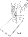
- Eine Ladevorrichtung zum Befüllen des Druckspeichers 3 des Magazins 12 mit Druckgas wird nachfolgend anhand der
Figuren 2 und3 näher erläutert. Eine solche Ladevorrichtung ist in ihrer Gesamtheit inFigur 2 mit dem Bezugszeichen 50 bezeichnet. Die Ladevorrichtung 50 dient zum Aufladen des pneumatischen Druckspeichers 13 mit einem Druckgas aus einer Druckgasquelle 52. Die Druckgasquelle 52 ist inFigur 2 nur symbolisch eingezeichnet. Sie kann bspw. als ein Kompressor oder als ein Hochdruck-Gastank ausgebildet sein, in dem eine große Menge an Druckgas gespeichert ist. Die Druckgasquelle 52 ist über eine Pneumatikleitung 54 mit der Ladevorrichtung 50 verbunden. Der Druckspeicher 13 ist in einem umgebauten Magazin angeordnet, wie bspw. dem Magazin 12 ausFigur 1 . Der Druckspeicher 13 ist - wie gesagt - ausgebildet, Druckgas für eine Schusswaffe, die für Übungszwecke umgerüstet ist, wie bspw. die Schusswaffe 1 ausFigur 1 , zur Simulation eines Rückstoßes der Schusswaffe 1 zur Verfügung zu stellen. - Die Ladevorrichtung 50 verfügt über eine Ladeposition 56 unmittelbar vor einer Auslassöffnung 58 der Ladevorrichtung 50. Die Ladeposition 56 umfasst in diesem Beispiel zwei auf gegenüberliegenden Seiten angeordnete Führungsschienen 60, in die der Randabschnitt 15 des Magazins 12 von oben eingeführt werden kann. Selbstverständlich kann die Ladeposition 56 auch beliebig anders ausgebildet sein, wie bspw. einer anderen, zeitgleich mit der vorliegenden Patentanmeldung eingereichten Patentanmeldung derselben Anmelderin im Detail entnommen werden kann. Bei vollständig in der Ladeposition 56 angeordnetem Magazin 12 bzw. bei vollständig (bis zu einem unteren Anschlag) in die Führungsschienen 60 eingeführtem Randabschnitt 15 befindet sich die an der Unterseite des Magazins 12 angeordnete Einfüllöffnung 34 des Druckspeichers 13 unmittelbar gegenüber der Auslassöffnung 58 der Ladevorrichtung 50. Dies ist in
Figur 3 gezeigt. - Die Auslassöffnung 58 liegt gasdicht abgedichtet an der Einfüllöffnung 34 bzw. 34' des Druckspeichers 13 an. Nachfolgend wird die Einfüllöffnung nur noch mit dem Bezugszeichen 34 bezeichnet, die Ausführungen gelten aber in entsprechender Weise auch für die Einfüllöffnung 34'. Wenn nun über die Auslassöffnung 58 der Ladevorrichtung 50 Druckgas aus der Druckgasquelle 52 zugeführt wird, fließt dieses Druckgas in Strömungsrichtung 70 über die Einfüllöffnung 34 und das entsprechende Rückschlagventil 40 in den Druckspeicher 30. Dies wird nachfolgend anhand der
Figur 4 näher erläutert, die das Rückschlagventil 40 in einer Durchflussposition zeigt, in der - wie gesagt - das Druckgas aus der Druckgasquelle 52 in den Druckspeicher 13 eingespeist wird. Man erkennt deutlich, dass der Druckspeicher 13 durch drei nebeneinander liegende und parallel zueinander verlaufende Bohrungen 72 realisiert ist, die über schräge Verbindungsbohrungen 74 miteinander in Verbindung stehen. Nach außen hin sind die beiden außen liegenden Bohrungen 72 mittels Stopfen 76 verschlossen, die in die Bohrungen 72 eingepresst oder eingeschraubt sein können. Ringförmige Dichtungen 78, die in an der Außenumfangsfläche der Stopfen 76 ausgebildeten Ringnuten 80 angeordneten sind, dichten die Stopfen 76 gegen die Bohrungen 72 ab. - Die mittlere Bohrung 72 ist mittels des Rückschlagventils 40 verschlossen. Der Einfüllöffnung 34 ist ein Rückschlagventil 40 zugeordnet, das den Durchfluss durch die Einfüllöffnung 34 steuert. Das Rückschlagventil 40 ist ausgebildet, in seiner Absperrposition die Einfüllöffnung 34 gasdicht zu verschließen, falls kein Druckgas aus der Druckgasquelle 52 an der Einfüllöffnung 34 anliegt, um ein Austreten des in dem Druckspeicher 13 gespeicherten Druckgases zu verhindern. Das Rückschlagventil 40 weist einen in einer Ventilbohrung 82 parallel zu der Strömungsrichtung 70 des Druckgases durch die Einfüllöffnung 34 bewegbaren Ventilkolben 84 auf. Dieser weist an seinem distalen Ende eine zur Außenseite des Magazins 12 gerichtete Außenfläche 86 auf und ist derart ausgebildet, dass die Außenfläche 86 des Ventilkolbens 84 in der Absperrposition (vgl.
Figur 5 ) des Rückschlagventils 40 bündig mit der Außenseite 88 des Magazins 12 abschließt. - Der Ventilkolben 84 hat einen kreisförmigen Querschnitt. Er weist einen zur Außenseite 88 des Magazins 12 hin gerichteten Führungsabschnitt 90 und einen zur Innenseite des Magazins 12 hin gerichteten Abdichtabschnitt 92 auf. Der Abdichtabschnitt 90 hat einen größeren Durchmesser als der Führungsabschnitt 92. Die Außenfläche 86 des Ventilkolbens 84 ist an dem distalen Ende des Führungsabschnitts 90 ausgebildet. An einem Übergang zwischen dem Führungsabschnitt 90 und dem Abdichtabschnitt 92 ist eine Stufe 94 ausgebildet, die eine zur Außenseite 88 des Magazins 12 hin gerichtete ringförmige Dichtfläche 96 umfasst, die in der Absperrposition (vgl.
Figur 5 ) des Rückschlagventils 40 auf einer entsprechenden in der Ventilbohrung 82 ausgebildeten ringförmigen Auflagefläche 98 aufliegt und den Druckspeicher 13 gasdicht abschließt, damit kein Druckgas aus dem Druckspeicher 13 entweichen kann. Dem Ventilkolben 84 ist ein ringförmiges Dichtelement 100 zugeordnet, das an der Außenseite des Führungsabschnitts 90 an der Dichtfläche 96 angeordnet ist und in der Absperrposition des Rückschlagventils 40 (vgl.Figur 5 ) zwischen der Dichtfläche 96 des Ventilkolbens 84 und der Auflagefläche 98 der Ventilbohrung 82 wirkt. - In einer Durchflussposition des Rückschlagventils 40 (vgl.
Figur 4 ), in der Druckgas aus der Druckgasquelle 52 über die Einfüllöffnung 34 in den pneumatischen Druckspeicher 13 des Magazins 12 fließen kann, ist die Dichtfläche 96 des Ventilkolbens 84 und das Dichtelement 100 beabstandet zu der Auflagefläche 98 der Ventilbohrung 82, so dass sich ein Ringspalt ergibt. In der Durchflussposition des Rückschlagventils 40 fließt somit Druckgas aus der Druckgasquelle 52 über die Einfüllöffnung 34 und zwischen einer Außenumfangsfläche des Führungsabschnitts 90 und einer Innenwandung der Ventilbohrung 82, durch den Ringspalt und zwischen einer Außenumfangsfläche des Abdichtabschnitts 92 und der Innenwandung der Ventilbohrung 82 in den pneumatischen Druckspeicher 13 des Magazins 12. - Vorzugsweise bewirken alleine der von außen an dem Ventilkolben 82 anliegende Druck des Druckgases aus der Druckgasquelle 52 und der von innen an dem Ventilkolben 82 anliegende Druck des in dem Druckspeicher 13 gespeicherten Druckgases eine Bewegung des Ventilkolbens 84 parallel zu der Strömungsrichtung 70 des Druckgases durch die Einfüllöffnung 34, wobei die beiden Drücke einander entgegengerichtet sind. In diesem Fall weist das Rückschlagventil 40 keine zusätzlichen Federelemente auf. Die an dem distalen Ende des Ventilkolbens 84 ausgebildete Außenfläche 86 kann zur Anzeige genutzt werden, ob in dem pneumatischen Druckspeicher 13 des Magazins 12 noch Druckgas unter Druck anliegt oder nicht.
- Das Rückschlagventil 40 weist einen Ventilkörper 102 auf, in dem die Ventilbohrung 82 ausgebildet ist, in der der Ventilkolben 84 hin und herbewegbar geführt ist. Der Ventilkörper 102 weist ein Außengewinde zum Einschrauben des Ventilkörpers 102 in eine entsprechende in dem Magazin 12 ausgebildete mit einem Innengewinde versehene Öffnung (die mittlere Bohrung 72) auf. Ferner umfasst das Rückschlagventil 40 ein mit einer Längsbohrung 104 versehenes Anschlagelement 106, das von der der Einfüllöffnung 34 gegenüberliegenden Seite in dem Ventilkörper 102 befestigt ist, das die Ventilbohrung 82 zur Innenseite des Magazins 12 hin bzw. in Richtung des Druckspeichers 13 verschließt und einen Anschlag für den Ventilkörper 84 in seiner Durchflussposition (vgl.
Figur 4 ) bildet, in der Druckgas aus der Druckgasquelle 52 über die Einfüllöffnung 34 in den pneumatischen Druckspeicher 13 des Magazins 12 fließen kann. Das Anschlagelement 106 weist vorzugsweise ein Außengewinde zum Einschrauben des Anschlagelements 106 in eine entsprechende in dem Ventilkörper 102 ausgebildete mit einem Innengewinde versehene Öffnung 108 aufweist, die in die Ventilbohrung 82 mündet. Über ein ringförmiges Dichtelement 110 ist der Ventilkörper 102 gegenüber der mittleren Bohrung 72 radial abgedichtet. - Die erfindungsgemäße umgerüstete Schusswaffe, bspw. die Schusswaffe 1 aus
Figur 1 , weist ein erfindungsgemäßes umgebautes Magazin 12 auf, wie es beispielhaft anhand derFiguren 4 und5 erläutert wurde.
Claims (13)
- Umgebautes Magazin (12) zum Einsetzen in eine Magazinaufnahme einer Schusswaffe (1), die für Übungs- oder Trainingszwecke umgerüstet ist und die eine pneumatische Vorrichtung (3; 9) zur Simulation eines Rückstoßes der Schusswaffe (1) bei Betätigung eines Abzugs (2) der Schusswaffe (1) sowie das umgebaute Magazin (12) aufweist, wobei das Magazin (12) einen pneumatischen Druckspeicher (13), in dem ein Druckgas zur Betätigung der pneumatischen Vorrichtung (3; 9) der Schusswaffe (1) gespeichert ist, und eine Einfüllöffnung (34; 34'), die zum Befüllen des pneumatischen Druckspeichers (13) mit Druckgas aus einer Druckgasquelle (52) vorgesehen ist, mit einem Rückschlagventil (40; 40') aufweist, das ausgebildet ist, in seiner Absperrposition den Druckspeicher (13) gasdicht abzuschließen, falls kein Druckgas aus der Druckgasquelle (52) an der Einfüllöffnung (34; 34') anliegt, um ein Austreten des in dem Druckspeicher (13) gespeicherten Druckgases zu verhindern, dadurch gekennzeichnet, dass das Rückschlagventil (40; 40') einen in einer Ventilbohrung (82) parallel zu der Strömungsrichtung (70) des Druckgases durch die Einfüllöffnung (34; 34') bewegbaren Ventilkolben (84) aufweist, der an seinem distalen Ende eine zur Außenseite (88) des Magazins (12) gerichtete Außenfläche (86) aufweist und derart ausgebildet ist, dass die Außenfläche (86) des Ventilkolbens (84) in der Absperrposition des Rückschlagventils (40; 40') bündig mit der Außenseite (88) des Magazins (12) abschließt.
- Magazin (12) nach Anspruch 1, dadurch gekennzeichnet, dass der Ventilkolben (84) einen kreisförmigen Querschnitt aufweist.
- Magazin (12) nach Anspruch 1 oder 2, dadurch gekennzeichnet, dass der Ventilkolben (84) einen zur Außenseite des Magazins (12) hin gerichteten Führungsabschnitt (90) und einen zur Innenseite des Magazins (12) hin gerichteten Abdichtabschnitt (92) aufweist, wobei der Abdichtabschnitt (92) einen größeren Durchmesser aufweist als der Führungsabschnitt (90) und die Außenfläche (86) des Ventilkolbens (84) an dem distalen Ende des Führungsabschnitts (90) ausgebildet ist.
- Magazin (12) nach Anspruch 3, dadurch gekennzeichnet, dass an einem Übergang zwischen dem Führungsabschnitt (90) und dem Abdichtabschnitt (92) eine Stufe (94) ausgebildet ist, die eine zur Außenseite des Magazins (12) hin gerichtete ringförmige Dichtfläche (96) umfasst, die in der Absperrposition des Rückschlagventils (40; 40') auf einer entsprechenden in der Ventilbohrung (82) ausgebildeten ringförmigen Auflagefläche (98) aufliegt und den pneumatischen Druckspeicher (13) des Magazins (12) gasdicht verschließt.
- Magazin (12) nach Anspruch 4, dadurch gekennzeichnet, dass dem Ventilkolben (84) ein ringförmiges Dichtelement (100) zugeordnet ist, das an der Außenseite des Führungsabschnitts (90) an der Dichtfläche (96) angeordnet ist und in der Absperrposition des Rückschlagventils (40; 40') zwischen der Dichtfläche (96) des Ventilkolbens (84) und der Auflagefläche (98) der Ventilbohrung (82) wirkt.
- Magazin (12) nach Anspruch 5, dadurch gekennzeichnet, dass in einer Durchflussposition des Rückschlagventils (40; 40'), in der Druckgas aus der Druckgasquelle (52) über die Einfüllöffnung (34; 34') in den pneumatischen Druckspeicher (13) des Magazins (12) fließen kann, die Dichtfläche (96) des Ventilkolbens (84) und das Dichtelement (100) beabstandet zu der Auflagefläche (98) der Ventilbohrung (82) ist, so dass sich ein Ringspalt ergibt.
- Magazin (12) nach Anspruch 5, dadurch gekennzeichnet, dass in der Durchflussposition des Rückschlagventils (40; 40') Druckgas aus der Druckgasquelle (52) zwischen einer Außenumfangsfläche des Führungsabschnitts (90) und einer Innenwandung der Ventilbohrung (82), durch den Ringspalt und zwischen einer Außenumfangsfläche des Abdichtabschnitts (92) und der Innenwandung der Ventilbohrung (82) in den pneumatischen Druckspeicher (13) des Magazins (12) fließt.
- Magazin (12) nach einem der Ansprüche 1 bis 7, dadurch gekennzeichnet, dass alleine der von außen an dem Ventilkolben (84) anliegende Druck des Druckgases aus der Druckgasquelle (52) und der von innen an dem Ventilkolben (84) anliegende Druck des in dem Druckspeicher (13) gespeicherten Druckgases eine Bewegung des Ventilkolbens (84) parallel zu der Strömungsrichtung (70) des Druckgases durch die Einfüllöffnung (34; 34') bewirken und das Rückschlagventil (40; 40') keine zusätzlichen Federelemente aufweist.
- Magazin (12) nach einem der Ansprüche 1 bis 8, dadurch gekennzeichnet, dass die an dem distalen Ende des Ventilkolbens (84) ausgebildete Außenfläche (86) zur Anzeige dient, ob in dem pneumatischen Druckspeicher (13) des Magazins (12) noch Druckgas unter Druck anliegt oder nicht.
- Magazin (12) nach einem der Ansprüche 1 bis 9, dadurch gekennzeichnet, dass das Rückschlagventil (40; 40') einen Ventilkörper (102) aufweist, in dem die Ventilbohrung (82) ausgebildet ist, in der der Ventilkolben (84) hin und herbewegbar geführt ist, wobei der Ventilkörper (102) ein Außengewinde zum Einschrauben des Ventilkörpers (102) in eine entsprechende in dem Magazin (12) ausgebildete mit einem Innengewinde versehene Öffnung (72) aufweist.
- Magazin (12) nach Anspruch 10, dadurch gekennzeichnet, dass das Rückschlagventil (40; 40') ein mit einer Längsbohrung (104) versehenes Anschlagelement (106) aufweist, das von der der Einfüllöffnung (34; 34') gegenüberliegenden Seite in dem Ventilkörper (102) befestigt ist, und das die Ventilbohrung (82) zur Innenseite des Magazins (12) hin verschließt und einen Anschlag für den Ventilkörper (84) in seiner Durchflussposition bildet, in der Druckgas aus der Druckgasquelle (52) über die Einfüllöffnung (34; 34') in den pneumatischen Druckspeicher (13) des Magazins (12) fließen kann.
- Magazin (12) nach Anspruch 11, dadurch gekennzeichnet, dass das Anschlagelement (106) ein Außengewinde zum Einschrauben des Anschlagelements (106) in eine entsprechende in dem Ventilkörper (102) ausgebildete mit einem Innengewinde versehene Öffnung (108) aufweist, die in die Ventilbohrung (82) mündet.
- Schusswaffe (1), die für Übungs- oder Trainingszwecke umgerüstet ist und die eine pneumatische Vorrichtung (3; 9) zur Simulation eines Rückstoßes der Schusswaffe (1) bei Betätigung eines Abzugs (2) der Schusswaffe (1) sowie ein umgebautes Magazin (12) mit einem pneumatischen Druckspeicher (13) aufweist, in dem ein Druckgas zur Betätigung der pneumatischen Vorrichtung (3; 9) der Schusswaffe (1) gespeichert ist, dadurch gekennzeichnet, dass die Schusswaffe (1) ein umgebautes Magazin (12) nach einem der Ansprüche 1 bis 12 aufweist.
Applications Claiming Priority (1)
| Application Number | Priority Date | Filing Date | Title |
|---|---|---|---|
| DE102017106440.0A DE102017106440A1 (de) | 2017-03-24 | 2017-03-24 | Umgebautes Magazin für eine zu Übungs- oder Trainingszwecken umgerüstete Schusswaffe und umgerüstete Schusswaffe mit einem solchen umgebauten Magazin |
Publications (2)
| Publication Number | Publication Date |
|---|---|
| EP3379193A1 true EP3379193A1 (de) | 2018-09-26 |
| EP3379193B1 EP3379193B1 (de) | 2021-05-12 |
Family
ID=61731705
Family Applications (1)
| Application Number | Title | Priority Date | Filing Date |
|---|---|---|---|
| EP18163114.4A Active EP3379193B1 (de) | 2017-03-24 | 2018-03-21 | Umgebautes magazin für eine zu übungs- oder trainingszwecken umgerüstete schusswaffe und umgerüstete schusswaffe mit einem solchen umgebauten magazin |
Country Status (2)
| Country | Link |
|---|---|
| EP (1) | EP3379193B1 (de) |
| DE (1) | DE102017106440A1 (de) |
Citations (6)
| Publication number | Priority date | Publication date | Assignee | Title |
|---|---|---|---|---|
| WO1998014745A1 (de) * | 1996-10-02 | 1998-04-09 | Kehl, Hermann | Laserpistole |
| US20090283084A1 (en) * | 2008-05-15 | 2009-11-19 | Real Action Paintball | Pneumatic Container and Paintball Gun Containing Same and Pneumatic Recharging System |
| US20120006445A1 (en) * | 2010-07-09 | 2012-01-12 | L'air Liquide, Societe Anonyme Pour L'etude Et L'exploitation Des Procedes Georges Claude | Filler coupling and corresponding receptacle and filling method |
| EP2737234A1 (de) * | 2011-07-26 | 2014-06-04 | L'Air Liquide Société Anonyme pour l'Etude et l'Exploitation des Procédés Georges Claude | Füllanschluss, behälter, füllverfahren und fülldüse |
| GB2512228A (en) * | 2014-06-20 | 2014-09-24 | David Guy Woodman | Snapshut valve |
| DE102015211619A1 (de) * | 2015-06-23 | 2016-12-29 | Thales Deutschland Gmbh | Umgebautes Magazin einer hydraulischen Vorrichtung zur Simulation eines Rückstoßes einer Feuerwaffe, die Teil eines Waffensimulators ist, Feuerwaffe mit einem solchen Magazin und Waffensimulator mit solchen Feuerwaffen |
Family Cites Families (4)
| Publication number | Priority date | Publication date | Assignee | Title |
|---|---|---|---|---|
| US4302190A (en) | 1979-12-19 | 1981-11-24 | The United States Of America As Represented By The Secretary Of The Navy | Rifle recoil simulator |
| GB9913038D0 (en) * | 1999-06-05 | 1999-08-04 | Bsa Guns | Improvements in and relating to air guns |
| ES2231346T3 (es) | 2001-06-02 | 2005-05-16 | Sicurta Ag | Pistola de laser y procedimiento de transformacion de una pistola convencional en una pistola de laser. |
| HK1079866B (en) | 2002-08-09 | 2009-11-20 | Meggitt Training Systems, Inc. | Gas operating system for firearm simulators |
-
2017
- 2017-03-24 DE DE102017106440.0A patent/DE102017106440A1/de not_active Ceased
-
2018
- 2018-03-21 EP EP18163114.4A patent/EP3379193B1/de active Active
Patent Citations (6)
| Publication number | Priority date | Publication date | Assignee | Title |
|---|---|---|---|---|
| WO1998014745A1 (de) * | 1996-10-02 | 1998-04-09 | Kehl, Hermann | Laserpistole |
| US20090283084A1 (en) * | 2008-05-15 | 2009-11-19 | Real Action Paintball | Pneumatic Container and Paintball Gun Containing Same and Pneumatic Recharging System |
| US20120006445A1 (en) * | 2010-07-09 | 2012-01-12 | L'air Liquide, Societe Anonyme Pour L'etude Et L'exploitation Des Procedes Georges Claude | Filler coupling and corresponding receptacle and filling method |
| EP2737234A1 (de) * | 2011-07-26 | 2014-06-04 | L'Air Liquide Société Anonyme pour l'Etude et l'Exploitation des Procédés Georges Claude | Füllanschluss, behälter, füllverfahren und fülldüse |
| GB2512228A (en) * | 2014-06-20 | 2014-09-24 | David Guy Woodman | Snapshut valve |
| DE102015211619A1 (de) * | 2015-06-23 | 2016-12-29 | Thales Deutschland Gmbh | Umgebautes Magazin einer hydraulischen Vorrichtung zur Simulation eines Rückstoßes einer Feuerwaffe, die Teil eines Waffensimulators ist, Feuerwaffe mit einem solchen Magazin und Waffensimulator mit solchen Feuerwaffen |
Also Published As
| Publication number | Publication date |
|---|---|
| EP3379193B1 (de) | 2021-05-12 |
| DE102017106440A1 (de) | 2018-09-27 |
Similar Documents
| Publication | Publication Date | Title |
|---|---|---|
| DE60310341T2 (de) | Spielzeugwaffe | |
| DE69700825T2 (de) | Luftdruckwaffe zum abschiessen von geschossen und verfahren zum abschiessen eines geschosses | |
| DE69837660T2 (de) | Elektronische zweidruck-luftdruckwaffe für paintbullgeschosse | |
| DE602004006925T2 (de) | Gasdruckspielzeugwaffe | |
| DE102015211619B4 (de) | Umgebaute Feuerwaffe, sowie Waffensimulator | |
| DE3505443A1 (de) | Luftdruckwaffe | |
| EP3109584B1 (de) | Umgebaute feuerwaffe, die teil eines waffensimulators ist und für übungszwecke umgerüstet ist sowie waffensimulator mit mindestens einer solchen umgebauten feuerwaffe | |
| EP2884221B1 (de) | Verfahren und Waffensimulator zum Trainieren der Benutzung und des Einsatzes von Schussswaffen, zentrale Steuerungseinheit eines Waffensimulators und Computerprogramm zur Realisierung des Verfahrens | |
| DE102013224209A1 (de) | Patrone zum Einsetzen in eine Schusswaffe eines Waffensimulators und umgebaute Schusswaffe eines Waffensimulators mit einer solchen Patrone | |
| DE102013225966A1 (de) | Vorrichtung zur Simulation eines Rückstoßes einer Feuerwaffe und Feuerwaffe mit einer solchen Vorrichtung | |
| DE3025970A1 (de) | Druckluft-schusswaffe, z.b. pistole oder karabiner | |
| DE102017106439B3 (de) | Ladevorrichtung zum Aufladen eines pneumatischen Druckspeichers und Ladestation mit mehreren solcher Ladevorrichtungen | |
| DE3714974A1 (de) | Artillerietrainingsvorrichtung mit vorlauf/ruecklaufsimulation | |
| EP2899493B1 (de) | Verfahren zum Trainieren der Benutzung und des Einsatzes von Feuerwaffen in einem Waffensimulator, Waffensimulator zur Ausführung eines solchen Verfahrens, zentraler Steuerrechner eines solchen Waffensimulators und Computerprogramm zum Ablauf auf einem solchen Steuerrechner | |
| EP2894430B1 (de) | Schusswaffe mit mehreren Sensoren zum Erfassen eines Betriebszustands der Schusswaffe | |
| EP3379193B1 (de) | Umgebautes magazin für eine zu übungs- oder trainingszwecken umgerüstete schusswaffe und umgerüstete schusswaffe mit einem solchen umgebauten magazin | |
| DE102014200531A1 (de) | Schusswaffe zur Verwendung in einem Waffensimulator, Ventilmittel für eine solche Schusswaffe und Waffensimulator für eine solche Schusswaffe | |
| DE102014200532A1 (de) | Verfahren und Vorrichtung zum Wiederaufladen einer hydraulischen Vorrichtung zur Simulation eines Rückstoßes einer Feuerwaffe | |
| DE102014225170A1 (de) | Für Übungszwecke umgerüstete Feuerwaffe eines Waffensimulators | |
| DE202018105702U1 (de) | Schießvorrichtung einer Spielzeugpistole | |
| CH654654A5 (de) | Tragbare vorrichtung in der form eines raketenrohres. | |
| DE618722C (de) | In den unveraenderten Schlosskasten eines Maschinen- oder Handgewehres zum Umwandeln in ein UEbungsgewehr einsetzbares und lediglich gegen das Schloss auszutauschendes Einsatzstueck | |
| CH624480A5 (en) | Muzzle-loading weapon, especially a mortar | |
| DE19839986B4 (de) | Druckgaswaffe mit Rückstoßausgleich | |
| DE4303881A1 (de) | Elektronisch gesteuertes Schießgerät |
Legal Events
| Date | Code | Title | Description |
|---|---|---|---|
| PUAI | Public reference made under article 153(3) epc to a published international application that has entered the european phase |
Free format text: ORIGINAL CODE: 0009012 |
|
| STAA | Information on the status of an ep patent application or granted ep patent |
Free format text: STATUS: THE APPLICATION HAS BEEN PUBLISHED |
|
| AK | Designated contracting states |
Kind code of ref document: A1 Designated state(s): AL AT BE BG CH CY CZ DE DK EE ES FI FR GB GR HR HU IE IS IT LI LT LU LV MC MK MT NL NO PL PT RO RS SE SI SK SM TR |
|
| AX | Request for extension of the european patent |
Extension state: BA ME |
|
| STAA | Information on the status of an ep patent application or granted ep patent |
Free format text: STATUS: REQUEST FOR EXAMINATION WAS MADE |
|
| 17P | Request for examination filed |
Effective date: 20190325 |
|
| RBV | Designated contracting states (corrected) |
Designated state(s): AL AT BE BG CH CY CZ DE DK EE ES FI FR GB GR HR HU IE IS IT LI LT LU LV MC MK MT NL NO PL PT RO RS SE SI SK SM TR |
|
| GRAP | Despatch of communication of intention to grant a patent |
Free format text: ORIGINAL CODE: EPIDOSNIGR1 |
|
| STAA | Information on the status of an ep patent application or granted ep patent |
Free format text: STATUS: GRANT OF PATENT IS INTENDED |
|
| INTG | Intention to grant announced |
Effective date: 20201201 |
|
| GRAS | Grant fee paid |
Free format text: ORIGINAL CODE: EPIDOSNIGR3 |
|
| GRAA | (expected) grant |
Free format text: ORIGINAL CODE: 0009210 |
|
| STAA | Information on the status of an ep patent application or granted ep patent |
Free format text: STATUS: THE PATENT HAS BEEN GRANTED |
|
| AK | Designated contracting states |
Kind code of ref document: B1 Designated state(s): AL AT BE BG CH CY CZ DE DK EE ES FI FR GB GR HR HU IE IS IT LI LT LU LV MC MK MT NL NO PL PT RO RS SE SI SK SM TR |
|
| REG | Reference to a national code |
Ref country code: GB Ref legal event code: FG4D Free format text: NOT ENGLISH |
|
| REG | Reference to a national code |
Ref country code: CH Ref legal event code: EP |
|
| REG | Reference to a national code |
Ref country code: DE Ref legal event code: R096 Ref document number: 502018005205 Country of ref document: DE |
|
| REG | Reference to a national code |
Ref country code: IE Ref legal event code: FG4D Free format text: LANGUAGE OF EP DOCUMENT: GERMAN |
|
| REG | Reference to a national code |
Ref country code: AT Ref legal event code: REF Ref document number: 1392462 Country of ref document: AT Kind code of ref document: T Effective date: 20210615 |
|
| REG | Reference to a national code |
Ref country code: NL Ref legal event code: FP |
|
| REG | Reference to a national code |
Ref country code: SE Ref legal event code: TRGR |
|
| REG | Reference to a national code |
Ref country code: LT Ref legal event code: MG9D |
|
| PG25 | Lapsed in a contracting state [announced via postgrant information from national office to epo] |
Ref country code: FI Free format text: LAPSE BECAUSE OF FAILURE TO SUBMIT A TRANSLATION OF THE DESCRIPTION OR TO PAY THE FEE WITHIN THE PRESCRIBED TIME-LIMIT Effective date: 20210512 Ref country code: LT Free format text: LAPSE BECAUSE OF FAILURE TO SUBMIT A TRANSLATION OF THE DESCRIPTION OR TO PAY THE FEE WITHIN THE PRESCRIBED TIME-LIMIT Effective date: 20210512 Ref country code: HR Free format text: LAPSE BECAUSE OF FAILURE TO SUBMIT A TRANSLATION OF THE DESCRIPTION OR TO PAY THE FEE WITHIN THE PRESCRIBED TIME-LIMIT Effective date: 20210512 Ref country code: BG Free format text: LAPSE BECAUSE OF FAILURE TO SUBMIT A TRANSLATION OF THE DESCRIPTION OR TO PAY THE FEE WITHIN THE PRESCRIBED TIME-LIMIT Effective date: 20210812 |
|
| PG25 | Lapsed in a contracting state [announced via postgrant information from national office to epo] |
Ref country code: IS Free format text: LAPSE BECAUSE OF FAILURE TO SUBMIT A TRANSLATION OF THE DESCRIPTION OR TO PAY THE FEE WITHIN THE PRESCRIBED TIME-LIMIT Effective date: 20210912 Ref country code: GR Free format text: LAPSE BECAUSE OF FAILURE TO SUBMIT A TRANSLATION OF THE DESCRIPTION OR TO PAY THE FEE WITHIN THE PRESCRIBED TIME-LIMIT Effective date: 20210813 Ref country code: PT Free format text: LAPSE BECAUSE OF FAILURE TO SUBMIT A TRANSLATION OF THE DESCRIPTION OR TO PAY THE FEE WITHIN THE PRESCRIBED TIME-LIMIT Effective date: 20210913 Ref country code: PL Free format text: LAPSE BECAUSE OF FAILURE TO SUBMIT A TRANSLATION OF THE DESCRIPTION OR TO PAY THE FEE WITHIN THE PRESCRIBED TIME-LIMIT Effective date: 20210512 Ref country code: NO Free format text: LAPSE BECAUSE OF FAILURE TO SUBMIT A TRANSLATION OF THE DESCRIPTION OR TO PAY THE FEE WITHIN THE PRESCRIBED TIME-LIMIT Effective date: 20210812 Ref country code: LV Free format text: LAPSE BECAUSE OF FAILURE TO SUBMIT A TRANSLATION OF THE DESCRIPTION OR TO PAY THE FEE WITHIN THE PRESCRIBED TIME-LIMIT Effective date: 20210512 Ref country code: RS Free format text: LAPSE BECAUSE OF FAILURE TO SUBMIT A TRANSLATION OF THE DESCRIPTION OR TO PAY THE FEE WITHIN THE PRESCRIBED TIME-LIMIT Effective date: 20210512 |
|
| PG25 | Lapsed in a contracting state [announced via postgrant information from national office to epo] |
Ref country code: SK Free format text: LAPSE BECAUSE OF FAILURE TO SUBMIT A TRANSLATION OF THE DESCRIPTION OR TO PAY THE FEE WITHIN THE PRESCRIBED TIME-LIMIT Effective date: 20210512 Ref country code: SM Free format text: LAPSE BECAUSE OF FAILURE TO SUBMIT A TRANSLATION OF THE DESCRIPTION OR TO PAY THE FEE WITHIN THE PRESCRIBED TIME-LIMIT Effective date: 20210512 Ref country code: EE Free format text: LAPSE BECAUSE OF FAILURE TO SUBMIT A TRANSLATION OF THE DESCRIPTION OR TO PAY THE FEE WITHIN THE PRESCRIBED TIME-LIMIT Effective date: 20210512 Ref country code: ES Free format text: LAPSE BECAUSE OF FAILURE TO SUBMIT A TRANSLATION OF THE DESCRIPTION OR TO PAY THE FEE WITHIN THE PRESCRIBED TIME-LIMIT Effective date: 20210512 Ref country code: RO Free format text: LAPSE BECAUSE OF FAILURE TO SUBMIT A TRANSLATION OF THE DESCRIPTION OR TO PAY THE FEE WITHIN THE PRESCRIBED TIME-LIMIT Effective date: 20210512 Ref country code: DK Free format text: LAPSE BECAUSE OF FAILURE TO SUBMIT A TRANSLATION OF THE DESCRIPTION OR TO PAY THE FEE WITHIN THE PRESCRIBED TIME-LIMIT Effective date: 20210512 Ref country code: CZ Free format text: LAPSE BECAUSE OF FAILURE TO SUBMIT A TRANSLATION OF THE DESCRIPTION OR TO PAY THE FEE WITHIN THE PRESCRIBED TIME-LIMIT Effective date: 20210512 |
|
| REG | Reference to a national code |
Ref country code: DE Ref legal event code: R097 Ref document number: 502018005205 Country of ref document: DE |
|
| PLBE | No opposition filed within time limit |
Free format text: ORIGINAL CODE: 0009261 |
|
| STAA | Information on the status of an ep patent application or granted ep patent |
Free format text: STATUS: NO OPPOSITION FILED WITHIN TIME LIMIT |
|
| 26N | No opposition filed |
Effective date: 20220215 |
|
| PG25 | Lapsed in a contracting state [announced via postgrant information from national office to epo] |
Ref country code: IS Free format text: LAPSE BECAUSE OF FAILURE TO SUBMIT A TRANSLATION OF THE DESCRIPTION OR TO PAY THE FEE WITHIN THE PRESCRIBED TIME-LIMIT Effective date: 20210912 Ref country code: AL Free format text: LAPSE BECAUSE OF FAILURE TO SUBMIT A TRANSLATION OF THE DESCRIPTION OR TO PAY THE FEE WITHIN THE PRESCRIBED TIME-LIMIT Effective date: 20210512 |
|
| PG25 | Lapsed in a contracting state [announced via postgrant information from national office to epo] |
Ref country code: IT Free format text: LAPSE BECAUSE OF FAILURE TO SUBMIT A TRANSLATION OF THE DESCRIPTION OR TO PAY THE FEE WITHIN THE PRESCRIBED TIME-LIMIT Effective date: 20210512 |
|
| PG25 | Lapsed in a contracting state [announced via postgrant information from national office to epo] |
Ref country code: MC Free format text: LAPSE BECAUSE OF FAILURE TO SUBMIT A TRANSLATION OF THE DESCRIPTION OR TO PAY THE FEE WITHIN THE PRESCRIBED TIME-LIMIT Effective date: 20210512 |
|
| REG | Reference to a national code |
Ref country code: CH Ref legal event code: PL |
|
| GBPC | Gb: european patent ceased through non-payment of renewal fee |
Effective date: 20220321 |
|
| REG | Reference to a national code |
Ref country code: BE Ref legal event code: MM Effective date: 20220331 |
|
| PG25 | Lapsed in a contracting state [announced via postgrant information from national office to epo] |
Ref country code: LU Free format text: LAPSE BECAUSE OF NON-PAYMENT OF DUE FEES Effective date: 20220321 Ref country code: LI Free format text: LAPSE BECAUSE OF NON-PAYMENT OF DUE FEES Effective date: 20220331 Ref country code: IE Free format text: LAPSE BECAUSE OF NON-PAYMENT OF DUE FEES Effective date: 20220321 Ref country code: GB Free format text: LAPSE BECAUSE OF NON-PAYMENT OF DUE FEES Effective date: 20220321 Ref country code: CH Free format text: LAPSE BECAUSE OF NON-PAYMENT OF DUE FEES Effective date: 20220331 |
|
| PG25 | Lapsed in a contracting state [announced via postgrant information from national office to epo] |
Ref country code: BE Free format text: LAPSE BECAUSE OF NON-PAYMENT OF DUE FEES Effective date: 20220331 |
|
| PG25 | Lapsed in a contracting state [announced via postgrant information from national office to epo] |
Ref country code: HU Free format text: LAPSE BECAUSE OF FAILURE TO SUBMIT A TRANSLATION OF THE DESCRIPTION OR TO PAY THE FEE WITHIN THE PRESCRIBED TIME-LIMIT; INVALID AB INITIO Effective date: 20180321 |
|
| PG25 | Lapsed in a contracting state [announced via postgrant information from national office to epo] |
Ref country code: MK Free format text: LAPSE BECAUSE OF FAILURE TO SUBMIT A TRANSLATION OF THE DESCRIPTION OR TO PAY THE FEE WITHIN THE PRESCRIBED TIME-LIMIT Effective date: 20210512 Ref country code: CY Free format text: LAPSE BECAUSE OF FAILURE TO SUBMIT A TRANSLATION OF THE DESCRIPTION OR TO PAY THE FEE WITHIN THE PRESCRIBED TIME-LIMIT Effective date: 20210512 |
|
| REG | Reference to a national code |
Ref country code: AT Ref legal event code: MM01 Ref document number: 1392462 Country of ref document: AT Kind code of ref document: T Effective date: 20230321 |
|
| PG25 | Lapsed in a contracting state [announced via postgrant information from national office to epo] |
Ref country code: AT Free format text: LAPSE BECAUSE OF NON-PAYMENT OF DUE FEES Effective date: 20230321 |
|
| PG25 | Lapsed in a contracting state [announced via postgrant information from national office to epo] |
Ref country code: AT Free format text: LAPSE BECAUSE OF NON-PAYMENT OF DUE FEES Effective date: 20230321 |
|
| PG25 | Lapsed in a contracting state [announced via postgrant information from national office to epo] |
Ref country code: MT Free format text: LAPSE BECAUSE OF FAILURE TO SUBMIT A TRANSLATION OF THE DESCRIPTION OR TO PAY THE FEE WITHIN THE PRESCRIBED TIME-LIMIT Effective date: 20210512 |
|
| PGFP | Annual fee paid to national office [announced via postgrant information from national office to epo] |
Ref country code: DE Payment date: 20250624 Year of fee payment: 8 |
|
| PG25 | Lapsed in a contracting state [announced via postgrant information from national office to epo] |
Ref country code: TR Free format text: LAPSE BECAUSE OF FAILURE TO SUBMIT A TRANSLATION OF THE DESCRIPTION OR TO PAY THE FEE WITHIN THE PRESCRIBED TIME-LIMIT Effective date: 20210512 |
|
| PGFP | Annual fee paid to national office [announced via postgrant information from national office to epo] |
Ref country code: SE Payment date: 20260323 Year of fee payment: 9 |
|
| PGFP | Annual fee paid to national office [announced via postgrant information from national office to epo] |
Ref country code: AT Payment date: 20260410 Year of fee payment: 5 |
|
| PGFP | Annual fee paid to national office [announced via postgrant information from national office to epo] |
Ref country code: NL Payment date: 20260323 Year of fee payment: 9 |
|
| PGFP | Annual fee paid to national office [announced via postgrant information from national office to epo] |
Ref country code: FR Payment date: 20260324 Year of fee payment: 9 |