EP3379193B1 - Chargeur adapté à une arme à feu destinée à des fins d'exercice ou de formation et arme à feu modifiée dotée d'un tel chargeur adapté - Google Patents
Chargeur adapté à une arme à feu destinée à des fins d'exercice ou de formation et arme à feu modifiée dotée d'un tel chargeur adapté Download PDFInfo
- Publication number
- EP3379193B1 EP3379193B1 EP18163114.4A EP18163114A EP3379193B1 EP 3379193 B1 EP3379193 B1 EP 3379193B1 EP 18163114 A EP18163114 A EP 18163114A EP 3379193 B1 EP3379193 B1 EP 3379193B1
- Authority
- EP
- European Patent Office
- Prior art keywords
- magazine
- compressed gas
- valve
- firearm
- pressure accumulator
- Prior art date
- Legal status (The legal status is an assumption and is not a legal conclusion. Google has not performed a legal analysis and makes no representation as to the accuracy of the status listed.)
- Active
Links
Images



Classifications
-
- F—MECHANICAL ENGINEERING; LIGHTING; HEATING; WEAPONS; BLASTING
- F41—WEAPONS
- F41A—FUNCTIONAL FEATURES OR DETAILS COMMON TO BOTH SMALLARMS AND ORDNANCE, e.g. CANNONS; MOUNTINGS FOR SMALLARMS OR ORDNANCE
- F41A33/00—Adaptations for training; Gun simulators
- F41A33/06—Recoil simulators
-
- F—MECHANICAL ENGINEERING; LIGHTING; HEATING; WEAPONS; BLASTING
- F41—WEAPONS
- F41B—WEAPONS FOR PROJECTING MISSILES WITHOUT USE OF EXPLOSIVE OR COMBUSTIBLE PROPELLANT CHARGE; WEAPONS NOT OTHERWISE PROVIDED FOR
- F41B11/00—Compressed-gas guns, e.g. air guns; Steam guns
- F41B11/60—Compressed-gas guns, e.g. air guns; Steam guns characterised by the supply of compressed gas
- F41B11/62—Compressed-gas guns, e.g. air guns; Steam guns characterised by the supply of compressed gas with pressure supplied by a gas cartridge
-
- F—MECHANICAL ENGINEERING; LIGHTING; HEATING; WEAPONS; BLASTING
- F41—WEAPONS
- F41B—WEAPONS FOR PROJECTING MISSILES WITHOUT USE OF EXPLOSIVE OR COMBUSTIBLE PROPELLANT CHARGE; WEAPONS NOT OTHERWISE PROVIDED FOR
- F41B11/00—Compressed-gas guns, e.g. air guns; Steam guns
- F41B11/70—Details not provided for in F41B11/50 or F41B11/60
- F41B11/72—Valves; Arrangement of valves
-
- F—MECHANICAL ENGINEERING; LIGHTING; HEATING; WEAPONS; BLASTING
- F41—WEAPONS
- F41B—WEAPONS FOR PROJECTING MISSILES WITHOUT USE OF EXPLOSIVE OR COMBUSTIBLE PROPELLANT CHARGE; WEAPONS NOT OTHERWISE PROVIDED FOR
- F41B11/00—Compressed-gas guns, e.g. air guns; Steam guns
- F41B11/70—Details not provided for in F41B11/50 or F41B11/60
- F41B11/73—Sealing arrangements; Pistons
-
- F—MECHANICAL ENGINEERING; LIGHTING; HEATING; WEAPONS; BLASTING
- F41—WEAPONS
- F41B—WEAPONS FOR PROJECTING MISSILES WITHOUT USE OF EXPLOSIVE OR COMBUSTIBLE PROPELLANT CHARGE; WEAPONS NOT OTHERWISE PROVIDED FOR
- F41B11/00—Compressed-gas guns, e.g. air guns; Steam guns
- F41B11/50—Magazines for compressed-gas guns; Arrangements for feeding or loading projectiles from magazines
- F41B11/55—Magazines for compressed-gas guns; Arrangements for feeding or loading projectiles from magazines the projectiles being stored in stacked order in a removable box magazine, rack or tubular magazine
- F41B11/56—Magazines for compressed-gas guns; Arrangements for feeding or loading projectiles from magazines the projectiles being stored in stacked order in a removable box magazine, rack or tubular magazine the magazine also housing a gas cartridge
Definitions
- the present invention relates to a magazine for insertion into a magazine receptacle of a firearm, which is converted for exercise or training purposes and which has a pneumatic device for simulating a recoil of the firearm when the trigger of the firearm is actuated, as well as the magazine.
- the magazine has a pneumatic pressure accumulator in which a compressed gas is used to operate the pneumatic device of the Firearm is stored, and a filler opening, which is provided for filling the pneumatic pressure accumulator with pressurized gas from a pressurized gas source, with a check valve.
- the check valve is designed to close the pressure accumulator gas-tight in its shut-off position if no compressed gas from the pressure gas source is present at the filling opening, in order to prevent the pressure gas stored in the pressure accumulator from escaping.
- the invention also relates to a firearm that is converted for exercise or training purposes and which has a pneumatic device for simulating a recoil of the firearm when the trigger of the firearm is actuated and a converted magazine with a pneumatic pressure accumulator in which a compressed gas for actuating the pneumatic Device of the firearm is stored.
- weapon simulators which simulate the firing of weapons. Firearms are used that have been converted for training purposes.
- the weapon simulators are mainly used in the military environment.
- U.S. 4,302,190 discloses a recoil simulator for a rifle in which compressed air is passed through openings in the gun barrel to move the gun barrel upward in a simulated recoil motion.
- a switch on the trigger activates an electromagnetic pneumatic valve to control the flow of air to the openings in the gun barrel.
- the recoil is not simulated by a slide that can be moved to and fro, but rather solely by a controlled air flow.
- a modified firearm for a weapon simulator in which a reciprocating shutter is pneumatically triggered by means of compressed air when the trigger is actuated.
- the known firearm has a pneumatic pressure accumulator included, from which air can escape via electromagnetically operated pneumatic valves when the trigger is actuated and can be used to move the shutter back and forth.
- Handguns modified for training purposes are known in which the pneumatic pressure accumulator, in which compressed gas is stored for actuating the device for simulating recoil of the weapon in the event of a shot being fired, is part of a modified magazine.
- the converted magazine is very similar to a real magazine, which contains cartridges to be fired by a real firearm. Just as a real magazine can be inserted into a magazine receptacle in the handle section of a real firearm, the converted magazine can be inserted into a magazine receptacle in the handle section of a converted firearm and detachably fastened therein.
- the pressure accumulator contains a certain amount of compressed gas so that a certain number of shots can be fired with the converted firearm. With each shot fired, part of the compressed gas stored in the pressure accumulator is released into the device for simulating a recoil. When the maximum possible number of shots has been reached, the pressure accumulator must be recharged, which can be done with a suitably designed charging device.
- the converted magazine with the pneumatic pressure accumulator has an outlet opening through which the into the
- Magazine receptacle in the grip portion of the converted firearm inserted magazine or the pneumatic pressure accumulator contained therein is connected to the device for simulating a recoil of the firearm.
- a check valve is assigned to the outlet opening of the converted magazine, which automatically closes the outlet opening as soon as the magazine is removed from the magazine receptacle and releases the outlet opening as soon as the magazine is completely inserted into the magazine receptacle.
- the converted magazine has a filling opening through which the pneumatic pressure accumulator can be filled with compressed gas.
- the filling opening of the converted magazine is assigned a check valve which automatically closes the filling opening as soon as the magazine is no longer connected to a compressed gas connection of a compressed gas source or no more compressed gas is flowing to charge the pressure accumulator, and the filling opening is released as soon as the magazine is connected to a compressed gas connection Pressurized gas source is connected and pressurized gas flows to charge the pressure accumulator.
- the check valves of the known converted magazines are usually constructed in a conventional manner, that is, they have a valve body, for example in the form of a ball, which is pressed against a valve seat by means of a spring element.
- Check valves designed in this way are, however, only for relatively low ones Suitable pressures are, for example, about 11 bar when using butane as the compressed gas or about 57 bar when using carbon dioxide as the compressed gas.
- Suitable pressures are, for example, about 11 bar when using butane as the compressed gas or about 57 bar when using carbon dioxide as the compressed gas.
- the magazine does not form a flat surface in the area of the filling opening and the check valve. Rather, the filling opening is always clearly visible, so that when the firearm provided with the known magazine is used, dirt and moisture can deposit in the filling opening, which then impairs the filling of the pneumatic pressure accumulator of the magazine with compressed gas, since a gas-tight connection between a Pressurized gas source of a loading device and the pressure accumulator of the magazine can then possibly no longer be produced.
- the magazine can only be opened safely for maintenance or repair purposes if there is no longer any compressed gas under pressure in the pressure accumulator. Otherwise the accumulator may explode when it is opened.
- the DE 10 2015 211 619 A1 describes a converted magazine of a hydraulic device for simulating a recoil of a firearm with a check valve designed as a ball, which can be filled with compressed air up to 300 bar.
- the US 2012/0006445 A1 describes a connection device for a pressure vessel which, on the one hand, has a conventional check valve for pressure-tight closing of the pressure vessel and, on the other hand, has an additional dust prevention valve.
- the present invention is therefore based on the object of designing and developing the known magazine in such a way that it can be filled with compressed gas at very high pressures in the range of about 250 to 300 bar via the filling opening so that the filling opening is protected against contamination and damage from the outside and that, if possible, it can also be recognized directly and clearly from the outside without additional aids whether the pressure accumulator of the magazine is depressurized or not.
- a magazine with the features of claim 1 is proposed.
- a converted magazine of the type mentioned is proposed, the non-return valve of which has a valve piston which can be moved in a valve bore parallel to the direction of flow of the compressed gas through the filling opening, which forms the closure part of the non-return valve and at its distal end a valve piston to the outside of the Magazine-directed outer surface and is designed such that the outer surface of the valve piston in the shut-off position of the check valve is flush with the outside of the magazine.
- the valve piston forms the closing part of the check valve. It is deliberately designed as a piston with an outer surface facing the outside of the magazine at a distal end of the piston. In the shut-off position of the check valve, this outer surface of the valve piston closes flush with the outside of the magazine around the filling opening, so that a flat outside of the magazine also results in the area of the filling opening. Penetration of dirt and / or moisture into the filling opening is effectively prevented.
- a gas-tight connection between a pressurized gas source of a loading device for filling the pneumatic pressure accumulator of the magazine with pressurized gas and the pressure accumulator of the magazine can be established with greater safety and reliability.
- an outlet opening of the loading device can be connected in a gas-tight manner to the filling opening of the magazine or of the pressure accumulator without problems due to contamination or moisture, in order to fill the pressure accumulator with compressed gas.
- the design of the closure part of the check valve as a valve piston results in a significantly more stable and robust design of the check valve, so that it is also very problem-free Can withstand high pressures in the range from 250 to 300 bar, such as occur, for example, when using compressed or compressed air when filling the pressure accumulator with compressed gas and in the pressure accumulator itself.
- the outer surface formed on the distal end of the valve piston serve to indicate whether or not compressed gas is still present under pressure in the pneumatic pressure accumulator of the magazine. This applies in particular when only the pressure of the compressed gas applied from the outside on the valve piston is released from the Pressurized gas source and the pressure of the pressurized gas stored in the pressure accumulator on the inside of the valve piston cause the valve piston to move parallel to the direction of flow of the pressurized gas through the filling opening and the check valve has no additional spring elements. In this case, the outer surface of the valve piston is flush with the outer surface of the magazine as long as the pneumatic pressure accumulator is under pressure.
- valve piston Only when the pressure accumulator is depressurized does the force no longer act on the valve piston, which could push it outwards into the shut-off position, and the valve piston falls into a retracted rest position in which the outer surface of the valve piston is immersed in the filling. This can be easily seen from outside the magazine without additional tools.
- the valve piston can move into the rest position either due to gravity or supported by an additional spring element as soon as the pressure in the pressure accumulator has fallen below a certain low pressure value. As a result, the safety when handling the magazine, in particular with regard to maintenance and repair, can be significantly improved.
- a firearm converted for training purposes as part of a weapon simulator is designated in its entirety by the reference symbol 1.
- the weapon simulator (not shown) is used to train operations that are as realistic as possible using converted firearms, such as the firearm 1.
- the weapon simulator can have a central control computer include, in which all firearms used in the vicinity of the weapon simulator, for example the firearm 1 and other retrofitted firearms, are registered or registered.
- the control computer is in a communication connection with the registered firearms, which can be implemented via an electrical line or wirelessly, for example via radio.
- the control computer is used to coordinate and evaluate training units for the individual registered firearms.
- a central control computer of the weapon simulator can also be dispensed with if, for example, the converted firearm 1 is used for recreational purposes.
- the firearm 1 resembles a real firearm in terms of its appearance and weight, as well as its haptics and operability.
- the firearm 1, however, has been converted so that it does not fire any blank cartridges or real ammunition.
- the various actions which take place in a real firearm before, during and after a shot is fired and which cause the weapon to recoil must therefore be simulated in the converted firearm 1.
- the firearm 1 has a device pneumatically operated by means of compressed gas for simulating a recoil when "firing" a simulated shot.
- sensors can be arranged that detect a current operating state of the firearm 1, and actuators can be provided that take appropriate actions depending on the current operating state, so that the use of the firearm 1 is as realistic as possible.
- a sensor 2 ' can detect the actuation of a trigger or trigger 2, which - if necessary after further conditions have been met - leads to the "firing" of a simulated shot.
- control electronics 17 can be activated and thus a laser 36 can be activated in order to emit a laser beam in the target direction from the barrel 38 of the weapon 1.
- the sensor 2 'and the control electronics 17 are only shown schematically; a person skilled in the art knows how to connect them to one another and how to switch them in such a way that the laser 36 is activated at the time the trigger 2 is actuated.
- a recoil of the firearm 1 is simulated.
- the movement of the closure 3 can be triggered, for example, by means of a shooting cylinder / piston arrangement 9.
- a further sensor (not shown) can be provided to detect the movement of the closure 3.
- the energy of a fired cartridge cannot be used to move the breech 3, since the retrofitted firearm 1 of the weapon simulator does not fire any cartridges or other ammunition.
- a hydraulic medium for example a gas, in particular air, is used to actuate the closure 3, which acts on the breech 3 or the shooting cylinder / piston arrangement 9 if necessary.
- a housing of the firearm 1 is denoted by the reference numeral 4.
- the housing 4 comprises a handle 10, which has an opening 11 on its lower end face, behind which a magazine receptacle formed in the interior of the handle 10 is hidden.
- a magazine with one or more cartridges contained therein is inserted and detachably fixed in the magazine receptacle.
- a converted magazine 12 is inserted into the magazine receptacle and fixed therein.
- a further sensor can be provided in order to detect a magazine 12 which has been properly inserted and fixed in the magazine receptacle.
- the converted magazine 12 resembles a real magazine in terms of its appearance and weight, as well as its feel and usability.
- the converted magazine 12 includes in its interior a pneumatic pressure accumulator 13 in which a compressed gas, for example air, is stored under high pressure, for example in the range from 200 to 300 bar.
- a compressed gas for example air
- the compressed gas stored in the pressure accumulator 13 is used to actuate the breech 3 when "firing" a "shot” with the firearm 1 to simulate a recoil of the weapon 1.
- the trigger 2 is actuated, the breech 3 is pushed back and forth by pressurized gas from the pressure accumulator 13 moved here. It is conceivable that only the backward movement of the closure 3 is generated by the pressurized gas, whereas the forward movement is generated in another way, e.g. by a return element (e.g. a compression spring) acting on the closure 3, as soon as there is no more pressurized gas the closure 3 rests.
- a return element e.g. a compression spring
- the pressure accumulator 13 of the converted magazine 12 is connected via a line 20 to an outlet opening 22 to which a check valve 24 is assigned, which closes the outlet opening 22 when the magazine 12 is not completely inserted into the magazine receptacle.
- the firearm 1 has a connecting piece 26 at the foot of the magazine receptacle, which protrudes into the outlet opening 22 when the magazine 12 is inserted and automatically opens the check valve 24 so that the compressed gas from the pressure accumulator 13 is applied to the pneumatic device for simulating the recoil of the firearm 1 .
- the flow of the compressed gas in the device for simulating the recoil can be controlled by means of electromagnetically controllable pneumatic valves, so that the compressed gas only rests against the breech 3 and triggers its back and forth movement, for example, only when a simulated “shot” is “fired”.
- the connecting piece 26 is provided on its outer circumferential surface with sealing rings 28, by means of which the connecting piece 26 is sealed against the inner wall of the outlet opening 22.
- an inlet opening 30 is formed, through which the compressed gas is discharged when the magazine 12 is completely inserted into the magazine receptacle the pressure accumulator 13 reaches the device for simulating the recoil of the firearm 1 via the line 20, the opened valve 24 and the outlet opening 22.
- the pressure accumulator 13 of the converted magazine 12 is also connected via a line 32 to a filling opening 34 to which a check valve 40 is also assigned, which closes the filling opening 34 when the magazine 12 is not at a loading station for charging the pressure accumulator 13 with a compressed gas is connected or if there is no compressed gas from a compressed gas source for charging the pressure accumulator 13.
- a filling opening can also be arranged on the side of the magazine 12.
- a corresponding filling opening 34 ' is shown in dashed lines and is connected to the pressure accumulator 13 via a line 32'.
- a non-return valve 40 ' is also assigned to this filling opening 34', the function of which corresponds to the non-return valve 40 of the filling opening 34.
- a laterally arranged filling opening 34 ' is less prone to damage and soiling, for example as a result of the weapon being dropped in the field.
- the filling openings 34, 34 ′ are arranged in a collar-shaped edge section 15 of the magazine 12. Of course, they can also be arranged at any other point on the outside of the magazine 12.
- the firearm 1 can comprise purely mechanically or pneumatically operated control means to control the pneumatic
- control means of the weapon 1 can also have electrical or electronic components which, for example, control electromagnetically actuated pneumatic valves in order to control the pneumatic actuation of the breech 3.
- the control means of the weapon 1 comprise electronic components, e.g. in the form of an electrical power supply device 16, control electronics 17 (e.g. a programmable microprocessor) and means 18 (e.g. a computer program that runs on the microprocessor) for sequence control of the firearm 1.
- FIG Figure 1 The components contained in the weapon 1 for actuating the breech 3 or a shooting cylinder / piston arrangement 9, which acts on the breech 3, are shown in FIG Figure 1 shown only schematically. Except for the in Figure 1 components shown and described above, further components, in particular further pneumatic lines and / or pneumatic valves, can be provided.
- the electrical energy supply device 16 of the weapon 1 is designed, for example, as a battery, preferably as a rechargeable battery.
- the energy supply device 16 can also comprise an electrical plug element (not shown) to which a cable for supplying energy to the weapon 1 can be connected from the outside.
- the weapon 1 can have at least one programmable microprocessor 17 and Have means (for example in the form of a computer program that runs on the microprocessor 17) for sequence control of the firearm 1.
- the computer program is preferably stored in an external or internal memory element of the microprocessor 17 and is used at the beginning of a training session or when the central control computer of the weapon simulator is started up (so-called "booting"), preferably immediately after the weapon 1 has been supplied with electrical energy from the energy supply device 16, loaded at least in sections into the microprocessor 17 and is there ready for processing or is being processed there.
- a loading device for filling the pressure accumulator 3 of the magazine 12 with compressed gas is described below with reference to FIG Figures 2 and 3 explained in more detail.
- a loading device is in its entirety in Figure 2 denoted by the reference numeral 50.
- the charging device 50 is used to charge the pneumatic pressure accumulator 13 with a pressurized gas from a pressurized gas source 52.
- the pressurized gas source 52 is shown in FIG Figure 2 only drawn symbolically. It can be designed, for example, as a compressor or as a high-pressure gas tank in which a large amount of pressurized gas is stored.
- the compressed gas source 52 is connected to the charging device 50 via a pneumatic line 54.
- the pressure accumulator 13 is arranged in a converted magazine, such as the magazine 12 from Figure 1 .
- the pressure accumulator 13 is - as mentioned - designed, compressed gas for a firearm which is converted for training purposes, such as, for example, the firearm 1 Figure 1 , for simulation a recoil of the firearm 1 available.
- the loading device 50 has a loading position 56 directly in front of an outlet opening 58 of the loading device 50.
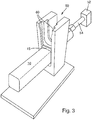
- the loading position 56 comprises two guide rails 60 arranged on opposite sides into which the edge section 15 of the magazine 12 can be inserted from above.
- the loading position 56 can also be designed in any other way, as can be seen in detail, for example, from another patent application filed by the same applicant at the same time as the present patent application.
- the outlet opening 58 rests against the filling opening 34 or 34 ′ of the pressure accumulator 13 in a gas-tight manner.
- the filling opening will only be designated by the reference number 34, but the explanations also apply in a corresponding manner to the filling opening 34 '.
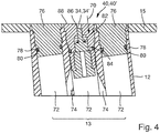
- the pressure accumulator 13 is realized by three bores 72 lying next to one another and running parallel to one another, which are connected to one another via inclined connecting bores 74.
- the two outer bores 72 are closed to the outside by means of plugs 76, which can be pressed or screwed into the bores 72.
- Annular seals 78 which are arranged in annular grooves 80 formed on the outer circumferential surface of the plugs 76, seal the plugs 76 against the bores 72.
- the middle bore 72 is closed by means of the check valve 40.
- the filling opening 34 is assigned a check valve 40 which controls the flow through the filling opening 34.
- the check valve 40 is designed to close the filling opening 34 gas-tight in its shut-off position if no compressed gas from the compressed gas source 52 is present at the filling opening 34, in order to prevent the compressed gas stored in the pressure accumulator 13 from escaping.
- the check valve 40 has a valve piston 84 that can be moved in a valve bore 82 parallel to the direction of flow 70 of the compressed gas through the filling opening 34. This has at its distal end an outer surface 86 directed towards the outside of the magazine 12 and is of this type designed that the outer surface 86 of the valve piston 84 in the shut-off position (cf. Figure 5 ) of the check valve 40 is flush with the outside 88 of the magazine 12.
- the valve piston 84 has a circular cross section. It has a guide section 90 directed towards the outside 88 of the magazine 12 and a sealing section 92 directed towards the inside of the magazine 12.
- the sealing section 90 has a larger diameter than the guide section 92.
- the outer surface 86 of the valve piston 84 is formed at the distal end of the guide section 90.
- a step 94 is formed which comprises an annular sealing surface 96 directed towards the outside 88 of the magazine 12, which in the shut-off position (cf.
- valve piston 84 is assigned an annular sealing element 100, which is arranged on the outside of the guide section 90 on the sealing surface 96 and in the shut-off position of the check valve 40 (cf. Figure 5 ) acts between the sealing surface 96 of the valve piston 84 and the bearing surface 98 of the valve bore 82.
- the valve piston 84 does not have any additional spring elements.
- the outer surface 86 formed on the distal end of the valve piston 84 can be used to indicate whether or not compressed gas is still present under pressure in the pneumatic pressure accumulator 13 of the magazine 12.
- the check valve 40 has a valve body 102 in which the valve bore 82 is formed, in which the valve piston 84 is guided such that it can move back and forth.
- the valve body 102 has an external thread for screwing in of the valve body 102 into a corresponding internally threaded opening formed in the magazine 12 (the central bore 72).
- the check valve 40 comprises a stop element 106 provided with a longitudinal bore 104, which is fastened from the side opposite the filling opening 34 in the valve body 102, which closes the valve bore 82 towards the inside of the magazine 12 or in the direction of the pressure accumulator 13, and a stop for the valve body 84 in its flow position (cf.
- Figure 4 forms, in which compressed gas can flow from the compressed gas source 52 via the filling opening 34 into the pneumatic pressure accumulator 13 of the magazine 12.
- the stop element 106 preferably has an external thread for screwing the stop element 106 into a corresponding opening 108 formed in the valve body 102 and provided with an internal thread, which opens into the valve bore 82.
- the valve body 102 is radially sealed off from the central bore 72 via an annular sealing element 110.
- the retrofitted firearm according to the invention for example the firearm 1 from Figure 1 , has a rebuilt magazine 12 according to the invention, as shown by way of example on the basis of FIG Figures 4 and 5 was explained.
Landscapes
- Engineering & Computer Science (AREA)
- General Engineering & Computer Science (AREA)
- Filling Or Discharging Of Gas Storage Vessels (AREA)
- Aiming, Guidance, Guns With A Light Source, Armor, Camouflage, And Targets (AREA)
Claims (12)
- Chargeur (12) pour un logement de chargeur d'une arme à feu (1) transformé pour des applications d'exercice ou d'entraînement et qui comporte un dispositif (3, 9) pour simuler le recul de l'arme à feu (1) lorsque la détente (2) de l'arme à feu (1) est actionnée ainsi que le chargeur (12) transformé,
le chargeur (12) ayant un accumulateur de pression pneumatique (13) contenant un gaz comprimé pour actionner le dispositif pneumatique (3, 9) de l'arme à feu (1) ainsi qu'un orifice de remplissage (34, 34') pour remplir l'accumulateur de pression pneumatique (13) avec du gaz sous pression d'une source de gaz comprimé (52),
comprenant un clapet antiretour (40, 40') formé pour qu'en position d'arrêt, il ferme l'accumulateur de pression (13) de manière étanche au gaz si aucun gaz comprimé de la source de gaz comprimé (52) n'est appliqué à l'orifice de remplissage (34, 34'), de façon à éviter la sortie du gaz sous pression contenu dans l'accumulateur sous pression (13), chargeur caractérisé en ce que
le clapet antiretour (40, 40') comporte un piston (84) mobile dans un perçage de clapet (82) parallèle à la direction de passage (70) du gaz comprimé à travers l'orifice de remplissage (34, 34'), et qui forme la pièce de fermeture du clapet antiretour (40, 40') ainsi qu'à son extrémité distale, une surface extérieure (86) orientée vers le côté extérieur (88) du chargeur (12) et réalisée de façon que la surface extérieure (86) du piston (84) en position de fermeture du clapet antiretour (40, 40') soit à niveau avec le côté extérieur (88) du chargeur (12) et que la surface extérieure (86) à l'extrémité distale du piston (84) serve d'indicateur indiquant s'il y a ou non encore du gaz comprimé dans l'accumulateur de pression pneumatique (13) du chargeur (12). - Chargeur (12) selon la revendication 1,
caractérisé en ce que
le piston (84) a une section circulaire. - Chargeur (12) selon la revendication 1 ou 2,
caractérisé en ce que
le piston (84) a un segment de guidage (90) orienté vers le côté extérieur du chargeur (12) et un segment d'étanchéité (92) orienté vers le côté intérieur du chargeur (12),
le segment d'étanchéité (92) ayant un diamètre plus grand que le segment de guidage (90) et la surface extérieure (86) du piston (84) est à l'extrémité distale du segment de guidage (90). - Chargeur (12) selon la revendication 3,
caractérisé en ce que
un gradin (94) est réalisé au passage entre le segment de guidage (90) et le segment d'étanchéité (92) qui comprend une surface d'étanchéité (96) annulaire, orientée vers le côté extérieur du chargeur (12) et qui, en position de fermeture du clapet antiretour (40, 40') s'appuie sur une surface d'appui (98) de forme annulaire réalisée en correspondance dans le perçage de clapet (82) et fermant de manière étanche aux gaz l'accumulateur de pression pneumatique (13) du chargeur (12). - Chargeur (12) selon la revendication 4,
caractérisé en ce que
un élément d'étanchéité (100) de forme annulaire est associé au piston (84) sur le côté extérieur du segment de guidage (90) contre la surface d'étanchéité (96) et en position de fermeture du clapet antiretour (40, 40'), il agit entre la surface d'étanchéité (96) du piston (84) et la surface d'appui (98) du perçage de clapet (82). - Chargeur (12) selon la revendication 5,
caractérisé en ce que
en position passante du clapet antiretour (40, 40'), dans laquelle le gaz comprimé de la source de gaz comprimé (52) peut arriver dans l'accumulateur de pression pneumatique (13) du chargeur (12) à travers l'orifice de remplissage (34, 34'), la surface d'étanchéité (96) du piston (84) et l'élément d'étanchéité (100) sont écartés de la surface d'appui (98) du perçage de clapet (82) pour laisser un intervalle annulaire. - Chargeur (12) selon la revendication 5,
caractérisé en ce que
en position passante du clapet antiretour (40, 40'), le gaz comprimé de la source de gaz comprimé (52) peut passer entre la surface périphérique extérieure du segment de guidage (90) et le perçage de clapet (82) dans la paroi intérieure, à travers l'intervalle annulaire et entre une surface périphérique extérieure du segment d'étanchéité (92) et la paroi intérieure du perçage de clapet (82) pour arriver dans l'accumulateur de pression pneumatique (13) du chargeur (12). - Chargeur (12) selon l'une des revendications 1 à 7,
caractérisé en ce que
la seule pression du gaz comprimé de la source de gaz comprimé (52) appliquée extérieurement sur le piston (84) et la pression appliquée à l'intérieur sur le piston (84) par le gaz comprimé du réservoir sous pression (13), déplace le piston de soupape (84) parallèlement à la direction de passage (70) du gaz comprimé à travers l'orifice de remplissage (34, 34') et le clapet antiretour (40, 40') ne comporte pas d'élément de ressort. - Chargeur (12) selon l'une des revendications 1 à 8,
caractérisé en ce que
le clapet antiretour (40, 40') comporte un corps (102) dans lequel est réalisé le perçage (82) guidant le piston (84) de manière mobile dans un sens et dans l'autre,
le corps de clapet (102) ayant un filetage extérieur pour se visser dans une ouverture (72) munie d'un filetage intérieur correspondant, réalisée dans le chargeur (12). - Chargeur (12) selon l'une des revendications 9,
caractérisé en ce que
le clapet antiretour (40, 40') comporte un élément de butée (106) muni d'un perçage longitudinal (104), cet élément étant fixé dans le corps de clapet (102) à partir du côté opposé à l'orifice de remplissage (34, 34') et il ferme le perçage (82) vers le côté intérieur du chargeur (12) et forme une butée pour le corps de soupape (84) dans sa position passante dans laquelle le gaz comprimé de la source de gaz comprimé (52) peut arriver dans l'accumulateur de pression pneumatique (13) du chargeur (12) en passant par l'orifice de remplissage (34, 34'). - Chargeur (12) selon la revendication 10,
caractérisé en ce que
l'élément de butée (106) a un filetage extérieur pour visser l'élément de butée (106) dans un orifice (108) correspondant, muni d'un filetage intérieur, dans le corps de clapet (102) et qui débouche dans le perçage de soupape (82). - Arme à feu (1) transformée pour l'exercice ou la formation et comportant un dispositif pneumatique (3, 9) pour simuler le recul de l'arme à feu (1) lors de l'actionnement de sa détente (2) ainsi qu'un chargeur (12) transformé, ayant un accumulateur de pression pneumatique (13) contenant du gaz comprimé pour actionner le dispositif pneumatique (3, 9) de l'arme à feu (1),
arme à feu (1) caractérisée en ce qu'elle comporte :
un chargeur (12) selon l'une des revendications 1 à 11.
Applications Claiming Priority (1)
| Application Number | Priority Date | Filing Date | Title |
|---|---|---|---|
| DE102017106440.0A DE102017106440A1 (de) | 2017-03-24 | 2017-03-24 | Umgebautes Magazin für eine zu Übungs- oder Trainingszwecken umgerüstete Schusswaffe und umgerüstete Schusswaffe mit einem solchen umgebauten Magazin |
Publications (2)
| Publication Number | Publication Date |
|---|---|
| EP3379193A1 EP3379193A1 (fr) | 2018-09-26 |
| EP3379193B1 true EP3379193B1 (fr) | 2021-05-12 |
Family
ID=61731705
Family Applications (1)
| Application Number | Title | Priority Date | Filing Date |
|---|---|---|---|
| EP18163114.4A Active EP3379193B1 (fr) | 2017-03-24 | 2018-03-21 | Chargeur adapté à une arme à feu destinée à des fins d'exercice ou de formation et arme à feu modifiée dotée d'un tel chargeur adapté |
Country Status (2)
| Country | Link |
|---|---|
| EP (1) | EP3379193B1 (fr) |
| DE (1) | DE102017106440A1 (fr) |
Family Cites Families (10)
| Publication number | Priority date | Publication date | Assignee | Title |
|---|---|---|---|---|
| US4302190A (en) | 1979-12-19 | 1981-11-24 | The United States Of America As Represented By The Secretary Of The Navy | Rifle recoil simulator |
| US6146141A (en) | 1996-10-02 | 2000-11-14 | Schumann; Edgar | Laser pistol |
| GB9913038D0 (en) * | 1999-06-05 | 1999-08-04 | Bsa Guns | Improvements in and relating to air guns |
| ES2231346T3 (es) | 2001-06-02 | 2005-05-16 | Sicurta Ag | Pistola de laser y procedimiento de transformacion de una pistola convencional en una pistola de laser. |
| HK1079866B (en) | 2002-08-09 | 2009-11-20 | Meggitt Training Systems, Inc. | Gas operating system for firearm simulators |
| US20090283084A1 (en) * | 2008-05-15 | 2009-11-19 | Real Action Paintball | Pneumatic Container and Paintball Gun Containing Same and Pneumatic Recharging System |
| FR2962519B1 (fr) * | 2010-07-09 | 2012-07-20 | Air Liquide | Raccord de remplissage, recipient et procede de remplissage correspondants |
| FR2978432B1 (fr) * | 2011-07-26 | 2014-12-05 | Air Liquide | Raccord de remplissage, recipient, procede de remplissage et prise de conditionnement |
| GB2512228A (en) * | 2014-06-20 | 2014-09-24 | David Guy Woodman | Snapshut valve |
| DE102015211619B4 (de) * | 2015-06-23 | 2022-01-27 | Thales Deutschland Gmbh | Umgebaute Feuerwaffe, sowie Waffensimulator |
-
2017
- 2017-03-24 DE DE102017106440.0A patent/DE102017106440A1/de not_active Ceased
-
2018
- 2018-03-21 EP EP18163114.4A patent/EP3379193B1/fr active Active
Non-Patent Citations (1)
| Title |
|---|
| None * |
Also Published As
| Publication number | Publication date |
|---|---|
| DE102017106440A1 (de) | 2018-09-27 |
| EP3379193A1 (fr) | 2018-09-26 |
Similar Documents
| Publication | Publication Date | Title |
|---|---|---|
| DE60310341T2 (de) | Spielzeugwaffe | |
| DE69700825T2 (de) | Luftdruckwaffe zum abschiessen von geschossen und verfahren zum abschiessen eines geschosses | |
| EP0929786A1 (fr) | Pistolet au laser | |
| DE102015211619B4 (de) | Umgebaute Feuerwaffe, sowie Waffensimulator | |
| EP3109584B1 (fr) | Arme a feu convertie faisant partie d'un simulateur d'arme et servant a s'exercer et simulateur d'arme comprenant au moins une telle arme a feu convertie | |
| DE102013224209A1 (de) | Patrone zum Einsetzen in eine Schusswaffe eines Waffensimulators und umgebaute Schusswaffe eines Waffensimulators mit einer solchen Patrone | |
| EP2884221B1 (fr) | Procédé et simulateur d'armes destiné à l'entraînement à l'utilisation et à l'usage d'armes à feu, unité de commande centrale d'un simulateur d'armes et programme informatique destiné à la réalisation du procédé | |
| DE102013225966A1 (de) | Vorrichtung zur Simulation eines Rückstoßes einer Feuerwaffe und Feuerwaffe mit einer solchen Vorrichtung | |
| EP3379193B1 (fr) | Chargeur adapté à une arme à feu destinée à des fins d'exercice ou de formation et arme à feu modifiée dotée d'un tel chargeur adapté | |
| DE3714974A1 (de) | Artillerietrainingsvorrichtung mit vorlauf/ruecklaufsimulation | |
| EP3379195B1 (fr) | Dispositif de chargement permettant de charger un accumulateur de pression pneumatique et station de chargement pourvue d'une pluralité de tels dispositifs de chargement | |
| EP2894430B1 (fr) | Arme de tir dotée de plusieurs capteurs destinés à détecter un état de fonctionnement de l'arme de tir | |
| DE102014200531A1 (de) | Schusswaffe zur Verwendung in einem Waffensimulator, Ventilmittel für eine solche Schusswaffe und Waffensimulator für eine solche Schusswaffe | |
| DE3048620A1 (de) | Ausbildungsschiessgeraet fuer kanonen, geschuetze o.dgl. | |
| DE102011008684A1 (de) | Nachrüstbares Magazin für ein Knicklaufluftgewehr | |
| CH654654A5 (de) | Tragbare vorrichtung in der form eines raketenrohres. | |
| DE102014225170A1 (de) | Für Übungszwecke umgerüstete Feuerwaffe eines Waffensimulators | |
| DE102009007750B3 (de) | Sicherheitseinrichtung einer lafetierbaren Waffe | |
| DE102014200532A1 (de) | Verfahren und Vorrichtung zum Wiederaufladen einer hydraulischen Vorrichtung zur Simulation eines Rückstoßes einer Feuerwaffe | |
| AT521701B1 (de) | Luftenergiepatrone | |
| DE618722C (de) | In den unveraenderten Schlosskasten eines Maschinen- oder Handgewehres zum Umwandeln in ein UEbungsgewehr einsetzbares und lediglich gegen das Schloss auszutauschendes Einsatzstueck | |
| DE19839986B4 (de) | Druckgaswaffe mit Rückstoßausgleich | |
| DE102015204809B4 (de) | Feuerwaffe | |
| DE102004047628A1 (de) | Waffensimulator | |
| DE19531233C2 (de) | Patrone für Luftdruckwaffe |
Legal Events
| Date | Code | Title | Description |
|---|---|---|---|
| PUAI | Public reference made under article 153(3) epc to a published international application that has entered the european phase |
Free format text: ORIGINAL CODE: 0009012 |
|
| STAA | Information on the status of an ep patent application or granted ep patent |
Free format text: STATUS: THE APPLICATION HAS BEEN PUBLISHED |
|
| AK | Designated contracting states |
Kind code of ref document: A1 Designated state(s): AL AT BE BG CH CY CZ DE DK EE ES FI FR GB GR HR HU IE IS IT LI LT LU LV MC MK MT NL NO PL PT RO RS SE SI SK SM TR |
|
| AX | Request for extension of the european patent |
Extension state: BA ME |
|
| STAA | Information on the status of an ep patent application or granted ep patent |
Free format text: STATUS: REQUEST FOR EXAMINATION WAS MADE |
|
| 17P | Request for examination filed |
Effective date: 20190325 |
|
| RBV | Designated contracting states (corrected) |
Designated state(s): AL AT BE BG CH CY CZ DE DK EE ES FI FR GB GR HR HU IE IS IT LI LT LU LV MC MK MT NL NO PL PT RO RS SE SI SK SM TR |
|
| GRAP | Despatch of communication of intention to grant a patent |
Free format text: ORIGINAL CODE: EPIDOSNIGR1 |
|
| STAA | Information on the status of an ep patent application or granted ep patent |
Free format text: STATUS: GRANT OF PATENT IS INTENDED |
|
| INTG | Intention to grant announced |
Effective date: 20201201 |
|
| GRAS | Grant fee paid |
Free format text: ORIGINAL CODE: EPIDOSNIGR3 |
|
| GRAA | (expected) grant |
Free format text: ORIGINAL CODE: 0009210 |
|
| STAA | Information on the status of an ep patent application or granted ep patent |
Free format text: STATUS: THE PATENT HAS BEEN GRANTED |
|
| AK | Designated contracting states |
Kind code of ref document: B1 Designated state(s): AL AT BE BG CH CY CZ DE DK EE ES FI FR GB GR HR HU IE IS IT LI LT LU LV MC MK MT NL NO PL PT RO RS SE SI SK SM TR |
|
| REG | Reference to a national code |
Ref country code: GB Ref legal event code: FG4D Free format text: NOT ENGLISH |
|
| REG | Reference to a national code |
Ref country code: CH Ref legal event code: EP |
|
| REG | Reference to a national code |
Ref country code: DE Ref legal event code: R096 Ref document number: 502018005205 Country of ref document: DE |
|
| REG | Reference to a national code |
Ref country code: IE Ref legal event code: FG4D Free format text: LANGUAGE OF EP DOCUMENT: GERMAN |
|
| REG | Reference to a national code |
Ref country code: AT Ref legal event code: REF Ref document number: 1392462 Country of ref document: AT Kind code of ref document: T Effective date: 20210615 |
|
| REG | Reference to a national code |
Ref country code: NL Ref legal event code: FP |
|
| REG | Reference to a national code |
Ref country code: SE Ref legal event code: TRGR |
|
| REG | Reference to a national code |
Ref country code: LT Ref legal event code: MG9D |
|
| PG25 | Lapsed in a contracting state [announced via postgrant information from national office to epo] |
Ref country code: FI Free format text: LAPSE BECAUSE OF FAILURE TO SUBMIT A TRANSLATION OF THE DESCRIPTION OR TO PAY THE FEE WITHIN THE PRESCRIBED TIME-LIMIT Effective date: 20210512 Ref country code: LT Free format text: LAPSE BECAUSE OF FAILURE TO SUBMIT A TRANSLATION OF THE DESCRIPTION OR TO PAY THE FEE WITHIN THE PRESCRIBED TIME-LIMIT Effective date: 20210512 Ref country code: HR Free format text: LAPSE BECAUSE OF FAILURE TO SUBMIT A TRANSLATION OF THE DESCRIPTION OR TO PAY THE FEE WITHIN THE PRESCRIBED TIME-LIMIT Effective date: 20210512 Ref country code: BG Free format text: LAPSE BECAUSE OF FAILURE TO SUBMIT A TRANSLATION OF THE DESCRIPTION OR TO PAY THE FEE WITHIN THE PRESCRIBED TIME-LIMIT Effective date: 20210812 |
|
| PG25 | Lapsed in a contracting state [announced via postgrant information from national office to epo] |
Ref country code: IS Free format text: LAPSE BECAUSE OF FAILURE TO SUBMIT A TRANSLATION OF THE DESCRIPTION OR TO PAY THE FEE WITHIN THE PRESCRIBED TIME-LIMIT Effective date: 20210912 Ref country code: GR Free format text: LAPSE BECAUSE OF FAILURE TO SUBMIT A TRANSLATION OF THE DESCRIPTION OR TO PAY THE FEE WITHIN THE PRESCRIBED TIME-LIMIT Effective date: 20210813 Ref country code: PT Free format text: LAPSE BECAUSE OF FAILURE TO SUBMIT A TRANSLATION OF THE DESCRIPTION OR TO PAY THE FEE WITHIN THE PRESCRIBED TIME-LIMIT Effective date: 20210913 Ref country code: PL Free format text: LAPSE BECAUSE OF FAILURE TO SUBMIT A TRANSLATION OF THE DESCRIPTION OR TO PAY THE FEE WITHIN THE PRESCRIBED TIME-LIMIT Effective date: 20210512 Ref country code: NO Free format text: LAPSE BECAUSE OF FAILURE TO SUBMIT A TRANSLATION OF THE DESCRIPTION OR TO PAY THE FEE WITHIN THE PRESCRIBED TIME-LIMIT Effective date: 20210812 Ref country code: LV Free format text: LAPSE BECAUSE OF FAILURE TO SUBMIT A TRANSLATION OF THE DESCRIPTION OR TO PAY THE FEE WITHIN THE PRESCRIBED TIME-LIMIT Effective date: 20210512 Ref country code: RS Free format text: LAPSE BECAUSE OF FAILURE TO SUBMIT A TRANSLATION OF THE DESCRIPTION OR TO PAY THE FEE WITHIN THE PRESCRIBED TIME-LIMIT Effective date: 20210512 |
|
| PG25 | Lapsed in a contracting state [announced via postgrant information from national office to epo] |
Ref country code: SK Free format text: LAPSE BECAUSE OF FAILURE TO SUBMIT A TRANSLATION OF THE DESCRIPTION OR TO PAY THE FEE WITHIN THE PRESCRIBED TIME-LIMIT Effective date: 20210512 Ref country code: SM Free format text: LAPSE BECAUSE OF FAILURE TO SUBMIT A TRANSLATION OF THE DESCRIPTION OR TO PAY THE FEE WITHIN THE PRESCRIBED TIME-LIMIT Effective date: 20210512 Ref country code: EE Free format text: LAPSE BECAUSE OF FAILURE TO SUBMIT A TRANSLATION OF THE DESCRIPTION OR TO PAY THE FEE WITHIN THE PRESCRIBED TIME-LIMIT Effective date: 20210512 Ref country code: ES Free format text: LAPSE BECAUSE OF FAILURE TO SUBMIT A TRANSLATION OF THE DESCRIPTION OR TO PAY THE FEE WITHIN THE PRESCRIBED TIME-LIMIT Effective date: 20210512 Ref country code: RO Free format text: LAPSE BECAUSE OF FAILURE TO SUBMIT A TRANSLATION OF THE DESCRIPTION OR TO PAY THE FEE WITHIN THE PRESCRIBED TIME-LIMIT Effective date: 20210512 Ref country code: DK Free format text: LAPSE BECAUSE OF FAILURE TO SUBMIT A TRANSLATION OF THE DESCRIPTION OR TO PAY THE FEE WITHIN THE PRESCRIBED TIME-LIMIT Effective date: 20210512 Ref country code: CZ Free format text: LAPSE BECAUSE OF FAILURE TO SUBMIT A TRANSLATION OF THE DESCRIPTION OR TO PAY THE FEE WITHIN THE PRESCRIBED TIME-LIMIT Effective date: 20210512 |
|
| REG | Reference to a national code |
Ref country code: DE Ref legal event code: R097 Ref document number: 502018005205 Country of ref document: DE |
|
| PLBE | No opposition filed within time limit |
Free format text: ORIGINAL CODE: 0009261 |
|
| STAA | Information on the status of an ep patent application or granted ep patent |
Free format text: STATUS: NO OPPOSITION FILED WITHIN TIME LIMIT |
|
| 26N | No opposition filed |
Effective date: 20220215 |
|
| PG25 | Lapsed in a contracting state [announced via postgrant information from national office to epo] |
Ref country code: IS Free format text: LAPSE BECAUSE OF FAILURE TO SUBMIT A TRANSLATION OF THE DESCRIPTION OR TO PAY THE FEE WITHIN THE PRESCRIBED TIME-LIMIT Effective date: 20210912 Ref country code: AL Free format text: LAPSE BECAUSE OF FAILURE TO SUBMIT A TRANSLATION OF THE DESCRIPTION OR TO PAY THE FEE WITHIN THE PRESCRIBED TIME-LIMIT Effective date: 20210512 |
|
| PG25 | Lapsed in a contracting state [announced via postgrant information from national office to epo] |
Ref country code: IT Free format text: LAPSE BECAUSE OF FAILURE TO SUBMIT A TRANSLATION OF THE DESCRIPTION OR TO PAY THE FEE WITHIN THE PRESCRIBED TIME-LIMIT Effective date: 20210512 |
|
| PG25 | Lapsed in a contracting state [announced via postgrant information from national office to epo] |
Ref country code: MC Free format text: LAPSE BECAUSE OF FAILURE TO SUBMIT A TRANSLATION OF THE DESCRIPTION OR TO PAY THE FEE WITHIN THE PRESCRIBED TIME-LIMIT Effective date: 20210512 |
|
| REG | Reference to a national code |
Ref country code: CH Ref legal event code: PL |
|
| GBPC | Gb: european patent ceased through non-payment of renewal fee |
Effective date: 20220321 |
|
| REG | Reference to a national code |
Ref country code: BE Ref legal event code: MM Effective date: 20220331 |
|
| PG25 | Lapsed in a contracting state [announced via postgrant information from national office to epo] |
Ref country code: LU Free format text: LAPSE BECAUSE OF NON-PAYMENT OF DUE FEES Effective date: 20220321 Ref country code: LI Free format text: LAPSE BECAUSE OF NON-PAYMENT OF DUE FEES Effective date: 20220331 Ref country code: IE Free format text: LAPSE BECAUSE OF NON-PAYMENT OF DUE FEES Effective date: 20220321 Ref country code: GB Free format text: LAPSE BECAUSE OF NON-PAYMENT OF DUE FEES Effective date: 20220321 Ref country code: CH Free format text: LAPSE BECAUSE OF NON-PAYMENT OF DUE FEES Effective date: 20220331 |
|
| PG25 | Lapsed in a contracting state [announced via postgrant information from national office to epo] |
Ref country code: BE Free format text: LAPSE BECAUSE OF NON-PAYMENT OF DUE FEES Effective date: 20220331 |
|
| PG25 | Lapsed in a contracting state [announced via postgrant information from national office to epo] |
Ref country code: HU Free format text: LAPSE BECAUSE OF FAILURE TO SUBMIT A TRANSLATION OF THE DESCRIPTION OR TO PAY THE FEE WITHIN THE PRESCRIBED TIME-LIMIT; INVALID AB INITIO Effective date: 20180321 |
|
| PG25 | Lapsed in a contracting state [announced via postgrant information from national office to epo] |
Ref country code: MK Free format text: LAPSE BECAUSE OF FAILURE TO SUBMIT A TRANSLATION OF THE DESCRIPTION OR TO PAY THE FEE WITHIN THE PRESCRIBED TIME-LIMIT Effective date: 20210512 Ref country code: CY Free format text: LAPSE BECAUSE OF FAILURE TO SUBMIT A TRANSLATION OF THE DESCRIPTION OR TO PAY THE FEE WITHIN THE PRESCRIBED TIME-LIMIT Effective date: 20210512 |
|
| REG | Reference to a national code |
Ref country code: AT Ref legal event code: MM01 Ref document number: 1392462 Country of ref document: AT Kind code of ref document: T Effective date: 20230321 |
|
| PG25 | Lapsed in a contracting state [announced via postgrant information from national office to epo] |
Ref country code: AT Free format text: LAPSE BECAUSE OF NON-PAYMENT OF DUE FEES Effective date: 20230321 |
|
| PG25 | Lapsed in a contracting state [announced via postgrant information from national office to epo] |
Ref country code: AT Free format text: LAPSE BECAUSE OF NON-PAYMENT OF DUE FEES Effective date: 20230321 |
|
| PG25 | Lapsed in a contracting state [announced via postgrant information from national office to epo] |
Ref country code: MT Free format text: LAPSE BECAUSE OF FAILURE TO SUBMIT A TRANSLATION OF THE DESCRIPTION OR TO PAY THE FEE WITHIN THE PRESCRIBED TIME-LIMIT Effective date: 20210512 |
|
| PGFP | Annual fee paid to national office [announced via postgrant information from national office to epo] |
Ref country code: DE Payment date: 20250624 Year of fee payment: 8 |
|
| PG25 | Lapsed in a contracting state [announced via postgrant information from national office to epo] |
Ref country code: TR Free format text: LAPSE BECAUSE OF FAILURE TO SUBMIT A TRANSLATION OF THE DESCRIPTION OR TO PAY THE FEE WITHIN THE PRESCRIBED TIME-LIMIT Effective date: 20210512 |
|
| PGFP | Annual fee paid to national office [announced via postgrant information from national office to epo] |
Ref country code: SE Payment date: 20260323 Year of fee payment: 9 |
|
| PGFP | Annual fee paid to national office [announced via postgrant information from national office to epo] |
Ref country code: AT Payment date: 20260410 Year of fee payment: 5 |
|
| PGFP | Annual fee paid to national office [announced via postgrant information from national office to epo] |
Ref country code: NL Payment date: 20260323 Year of fee payment: 9 |
|
| PGFP | Annual fee paid to national office [announced via postgrant information from national office to epo] |
Ref country code: FR Payment date: 20260324 Year of fee payment: 9 |