EP3379228A1 - Sonde de prélèvement de gaz, récipient de gaz comprenant une telle sonde de prélèvement de gaz et procédé de prélèvement d'un échantillon gazeux à l'aide d'une telle sonde - Google Patents
Sonde de prélèvement de gaz, récipient de gaz comprenant une telle sonde de prélèvement de gaz et procédé de prélèvement d'un échantillon gazeux à l'aide d'une telle sonde Download PDFInfo
- Publication number
- EP3379228A1 EP3379228A1 EP17161873.9A EP17161873A EP3379228A1 EP 3379228 A1 EP3379228 A1 EP 3379228A1 EP 17161873 A EP17161873 A EP 17161873A EP 3379228 A1 EP3379228 A1 EP 3379228A1
- Authority
- EP
- European Patent Office
- Prior art keywords
- gas
- sampling probe
- line
- channel
- section
- Prior art date
- Legal status (The legal status is an assumption and is not a legal conclusion. Google has not performed a legal analysis and makes no representation as to the accuracy of the status listed.)
- Granted
Links
Images



Classifications
-
- G—PHYSICS
- G01—MEASURING; TESTING
- G01N—INVESTIGATING OR ANALYSING MATERIALS BY DETERMINING THEIR CHEMICAL OR PHYSICAL PROPERTIES
- G01N1/00—Sampling; Preparing specimens for investigation
- G01N1/02—Devices for withdrawing samples
- G01N1/22—Devices for withdrawing samples in the gaseous state
- G01N1/2202—Devices for withdrawing samples in the gaseous state involving separation of sample components during sampling
- G01N1/2214—Devices for withdrawing samples in the gaseous state involving separation of sample components during sampling by sorption
-
- G—PHYSICS
- G01—MEASURING; TESTING
- G01N—INVESTIGATING OR ANALYSING MATERIALS BY DETERMINING THEIR CHEMICAL OR PHYSICAL PROPERTIES
- G01N1/00—Sampling; Preparing specimens for investigation
- G01N1/02—Devices for withdrawing samples
- G01N1/22—Devices for withdrawing samples in the gaseous state
- G01N1/2247—Sampling from a flowing stream of gas
-
- G—PHYSICS
- G01—MEASURING; TESTING
- G01N—INVESTIGATING OR ANALYSING MATERIALS BY DETERMINING THEIR CHEMICAL OR PHYSICAL PROPERTIES
- G01N1/00—Sampling; Preparing specimens for investigation
- G01N1/28—Preparing specimens for investigation including physical details of (bio-)chemical methods covered elsewhere, e.g. G01N33/50, C12Q
- G01N1/40—Concentrating samples
- G01N1/405—Concentrating samples by adsorption or absorption
-
- G—PHYSICS
- G01—MEASURING; TESTING
- G01N—INVESTIGATING OR ANALYSING MATERIALS BY DETERMINING THEIR CHEMICAL OR PHYSICAL PROPERTIES
- G01N1/00—Sampling; Preparing specimens for investigation
- G01N1/02—Devices for withdrawing samples
- G01N1/22—Devices for withdrawing samples in the gaseous state
- G01N2001/2285—Details of probe structures
Definitions
- the invention relates to a gas sampling probe, a gas container with such a gas sampling probe attached thereto and a method for removing a gas sample from a gas of a gas container by means of such a gas sampling probe.
- Gas sampling probes are used to remove a gas sample from a gas, which may be present in particular in a gas container.
- the withdrawn gas sample can then be fed to an analysis.
- the analysis can serve to qualitatively and / or quantitatively determine certain substances in the gas. These substances may be, for example, environmental or health-endangering substances.
- Gas sampling probes may have a gas line in which a gas channel is formed, through which a gas can flow.
- the gas line can have a gas inlet, through which a gas can be introduced into the gas channel.
- the gas line of the gas sampling probe is introduced into a gas such that gas can flow through the gas inlet into the gas channel.
- the gas entering the gas channel serves as a gas sample, which can then be analyzed as above.
- adsorption material in the gas channel of such a generic gas sampling probe.
- substances of the gas to be analyzed can be adsorbed.
- the adsorption material is arranged in the region of the gas inlet in the gas channel. The gas introduced into the gas passage through the gas inlet then passes through the adsorption material, whereby substances of the gas are adsorbed by the adsorption material.
- the gas line of the gas sampling probe is pulled out of the gas and the adsorption material is removed from the gas channel in the region of the gas inlet.
- the removed adsorbent material can finally be analyzed for any adsorbed substances.
- the invention has for its object to provide a gas sampling probe available in which the gas line does not have to be removed from a gas to be analyzed in order to remove in the gas channel of the gas line arranged adsorbent material for its analysis from the gas line.
- a further object of the invention is to provide a gas sampling probe in which the gas line does not have to be removed from a gas to be analyzed in order to be able to carry out a leak test of the gas channel of the gas line.
- Another object of the invention is to provide a gas container with such a gas sampling probe attached thereto.
- Another object of the invention is to provide a method for taking a gas sample with such a gas sampling probe available.
- a basic idea of the invention is to arrange the adsorption material downstream of the gas inlet in the gas channel and at the same time to provide a valve by means of which the gas channel between the gas inlet and the adsorption material can be shut off. This makes it possible, on the one hand, to remove the adsorption material from the gas channel without first having to remove the gas line from the gas to be analyzed. At the same time, this makes it possible to carry out a leak test of the gas channel without first having to remove the gas line from the analyzing gas.
- the portion of the gas conduit disposed in a gas to be analyzed may remain in this gas, while the adsorbent material disposed in the gas passage downstream of the gas inlet may be taken out of the gas passage. It can be provided in particular that the valve the gas channel between the gas inlet and the adsorption material shut off while the adsorption material is removed from the gas channel.
- the tightness test can be performed simply by shutting off the gas channel between the gas inlet and the adsorption material and then determining the negative pressure in the gas channel downstream of the valve.
- the section of the gas channel lying downstream of the valve can be subjected to a negative pressure by a gas pump and, at the same time, the negative pressure in this section of the gas line can be determined.
- the gas line may in principle be in the form of any known from the prior art gas line, ie a conduit in which a gas channel is formed, through which a gas can flow or be passed.
- the gas line may be formed, for example, of one or more tubes or hoses for conducting a gas.
- the gas line is formed such that an exhaust gas, in particular a combustion gas can be conducted through this.
- the gas line is preferably designed such that through these a hot gas and / or a corrosive gas can be conducted.
- the gas line consists of a heat-resistant and / or non-corrosive material, in particular of metal (preferably of steel or a steel alloy) glass or ceramic.
- the gas line is formed of metal and / or glass.
- the gas channel formed in the gas line can basically have any desired cross-section.
- the gas channel has a circular cross section. This has the advantage that gas can flow very uniformly, in particular laminar, through the gas channel.
- the gas line has a gas inlet, which is designed such that it can be introduced or flowed into the gas channel through this gas.
- the gas inlet is formed as an end opening of the gas line.
- Downstream in the sense of the present invention therefore means in the flow direction of a gas introduced into the gas channel through the gas inlet and flowing through the gas channel.
- downstream of the gas inlet in the flow direction of the gas behind the gas inlet.
- the gas inlet is formed in a portion of the gas conduit that is configured to be located in a gas.
- This gas is a gas from which a sample can be taken by the gas sampling probe according to the invention.
- this section of the gas line can be arranged in a gas and gas from this gas can flow into the gas channel of the gas line via the gas inlet.
- This section of the gas line is preferably designed such that it can be arranged in an exhaust gas, in particular in a combustion gas.
- this section of the gas line can preferably be designed such that it can be arranged in a hot gas and / or in a corrosive gas.
- this section of the gas line may preferably consist of a heat-resistant and / or non-corrosive material, in particular of a metal (in particular a steel or a steel alloy).
- an adsorption material Downstream of the gas inlet, ie in the flow direction of the gas flowing through the gas inlet into the gas channel behind the gas inlet, an adsorption material is arranged in the gas channel of the gas line.
- the adsorption material is designed for the adsorption of at least one substance of a gas, in particular for the absorption of any substances harmful to the environment or health in the gas which can be flowed through the gas channel.
- These substances may, for example, be one or more of the following substances: at least one heavy metal (in particular mercury), dioxin or furans.
- the adsorption material can be designed for the adsorption of mercury.
- the adsorption material is in the form of bulk material, that is to say as a free-flowing bulk material, in particular in the form of a grain mixture.
- the adsorption material may be present, for example, in the form of granules, in particular, for example, in the form of semolina.
- the adsorption material may be formed as bulk material through which a gas can flow.
- the adsorbent material formed as bulk material has a particle size such that it can be flowed through by gas.
- any substance can be present as the adsorption material, by means of which one or more substances, with respect to which the gas sample to be sampled by the gas sampling probe is to be analyzed, can be adsorbed.
- a respective suitable adsorbate can be used for each substance to be analyzed become.
- coal is present as adsorption material.
- the particular advantage of coal as adsorption material is, in particular, that very numerous substances can be adsorbed by coal, in particular, for example, mercury.
- the adsorption material can be present in the extent of coal, which may be formed in particular as above as bulk material.
- the portion of the gas line in which the adsorption material is arranged in the gas channel of the gas line is completely filled with the adsorption material.
- the gas channel or the flow cross-section of the gas channel is completely filled with the adsorption material in the section of the gas line in which the adsorption material is arranged.
- the adsorption material is arranged in a section of the gas line, which is arranged removably in the gas line. Accordingly, this section of the gas line can be detached from the gas line or can be separated from the sections of the gas line which are adjacent to this section and can thus be removed from the gas line.
- this removable from the gas line section can also be used again in the gas line.
- the adsorbent material is disposed in a portion of the gas conduit formed of glass.
- This has the particular advantage that a possible undesired reaction between the adsorption material and the glass is excluded, since glass reacts practically with no material and in this respect is practically inert. In that regard, virtually no substances of the glass can be adsorbed by the adsorption material and thereby falsify any analysis of the adsorption material.
- soda-lime glass can be used as glass for this section, but preferably laboratory glass, in particular borosilicate glass.
- the formed from glass portion of the gas line in which the adsorbent material is arranged for example, as a tube, so be designed as a glass tube.
- the tube can be connected to the adjoining sections of the gas line.
- connecting means for connecting pipes or pipe sections.
- the glass-formed portion of the gas line, in which the adsorbent material is arranged via connecting means in the form of connectors or screw with the adjoining Be connected to sections of the gas line.
- suitable seals may be provided, for example sealing rings, in particular for example O-rings.
- the valve by which the gas channel between the gas inlet and the adsorption material can be shut off, can in principle be any valve according to the prior art, by which a gas line or a gas channel in a gas line can be shut off.
- the valve may be a needle valve or a ball valve.
- the valve is preferably a solenoid valve, that is to say an electromagnetically addressable valve. This has the advantage that the valve is particularly simple, in particular electrically operated.
- the gas sampling probe comprises a fastening means for fastening the gas sampling probe to a wall of a gas container.
- the gas sampling probe is particularly easy to attach to a wall of a gas container.
- a gas container in the sense of the invention can be any device by which a gas can be stored or conducted, in particular an exhaust gas, in particular a combustion gas can be stored or routed.
- the wall of the gas container, to which the gas sampling probe can be fastened via the fastening means delimits a corresponding gas, that is to say an interior space for receiving the gas which can be stored or passed through the gas container.
- the gas container may be in the form of an exhaust gas line, in particular in the form of a combustion gas line.
- the gas sampling probe in particular a fastening means for Attachment of the gas sampling probe on a wall of an exhaust pipe, in particular on a wall of a combustion gas line.
- the fastening means may be designed such that the gas sampling probe can be fastened to the wall via the fastening means in such a way that the section of the gas line on which the gas inlet is arranged is arranged inside the gas container.
- the fastening means is designed such that the gas sampling probe can be fastened to the wall of the gas container via the fastening means such that the section of the gas line on which the gas inlet is arranged is arranged inside the gas container and the section of the gas line in which the adsorption material is arranged, is arranged outside the gas container.
- This has the particular advantage that the adsorption material can be removed particularly easily from the gas line, in particular also without having to remove the gas line from the gas container before.
- the removal of the adsorption material is particularly simple if the gas sampling probe, as stated above, is designed in such a way that the adsorption material is arranged in a section of the gas line which is arranged removably in the gas line.
- the fastening means of the gas sampling probe can be designed such that the gas sampling probe can be attached to the wall via the fastening means such that the valve is arranged outside the gas container.
- this has the advantage that the valve is not attacked in this case by any hot or aggressive gases in the gas tank and the gas sampling probe can therefore be operated very low maintenance.
- Another advantage is that the valve is particularly easy to use.
- the gas sampling probe comprises a gas pump, through which the gas channel can be subjected to negative pressure, wherein the gas channel is preferably connected to the gas pump downstream of the adsorption material.
- the gas channel downstream of the adsorption leads to a gas pump through which the gas channel is subjected to negative pressure.
- the gas pump can be any pump through which gas can be pumped and thus the gas channel can be subjected to negative pressure.
- the gas pump may be a bellows pump.
- the gas sampling probe can comprise a heating means, by means of which the section of the gas line in which the adsorption material is arranged can be heated.
- heating means may be arranged, through which this section of the gas line can be heated.
- these heating means may be resistance heating elements.
- Such heating means have the particular advantage that a formation of condensed liquid in this section of the gas line, in which the adsorption material is arranged, can be prevented by heating this section by the heating means.
- This has the advantage that by avoiding condensation liquid in the region of the adsorption material, a deteriorated adsorption by the adsorption material due to condensation liquid can be prevented.
- the gas sampling probe comprises an envelope, by means of which the section of the gas line in which the adsorption material is arranged can be enveloped at least in sections.
- this enclosure may be a cylindrical enclosure, for example a metal enclosure.
- This envelope may, for example, have a substantially circular cylindrical shape which is disposed around the portion of the gas conduit in which the adsorbent material is disposed.
- the interior of this envelope can be heated, in particular by the heating means formed as described above. By the interior of the envelope is heated and in the interior of the envelope at the same time the portion of the gas line in which the adsorbent material is arranged, this section can be heated very effectively.
- an enclosure in particular, for example, a cylindrical enclosure, have an end cover in which a portion of the gas line is formed.
- a cover of the enclosure formed portion of the gas line to be formed for connection to the portion of the gas line in which the adsorbent material is arranged, in particular, for example, a removable portion, as stated above.
- a lid of the envelope is designed such that it can be fastened to the envelope in such a way that, in its position fastened to the envelope, it locates a section of the gas line in which the adsorption material is arranged and which is removable in the gas line, holds in a secured position in the gas line and allows for removal of the lid, the removal of this section from the gas line.
- a portion of the gas line which is connectable to the portion of the gas line in which the adsorbent material is arranged.
- the gas sampling probe further comprises a pressure measuring device by means of which the gas pressure in the gas channel can be measured.
- a pressure measuring device can be any device known from the prior art, by means of which a gas pressure in a gas line can be measured.
- the pressure measuring device the gas pressure in the gas line downstream of the valve can be measured.
- the gas sampling probe can comprise a flow measuring device, by means of which the gas flow in the gas channel can be measured.
- This flow measuring device can be any prior art flow measuring device by which a gas flow in a gas line can be measured.
- the gas flow in the gas line downstream of the valve can be measured by the flow measuring device.
- the particular advantage of such a pressure measuring device and of such a flow measuring device lies in the fact that it can be used to measure the gas pressure and the gas flow in the gas channel, while gas flows through the gas channel. This makes it possible to determine which gas flow has flowed through the gas channel as a whole. On the basis of such a determination of the gas flowed through the gas channel and the analysis, in particular the quantitative analysis of a substance adsorbed by the adsorbent material, the concentration of this substance in the gas to be analyzed can be determined.
- a gas pump through which the gas channel can be acted upon by negative pressure, has in particular two advantages.
- gas can be sucked into the gas channel via the gas inlet, so that gas to be analyzed flows through the adsorption material.
- the gas pump can be used to perform the leak test of the gas sampling probe.
- the valve is closed and the gas channel downstream of the valve by means of the gas pump subjected to negative pressure.
- the subject matter of the invention is also a gas container which comprises a wall which delimits a gas, to which wall a gas sampling probe according to the invention is attached.
- This gas container can be a gas container as described above, that is to say in particular, for example, a combustion gas line.
- the gas sampling probe as stated above, be fastened by fastening means on the wall of the gas container, that the portion of the gas line, on which the gas inlet is arranged, is disposed within the gas container.
- the portion of the gas line in which the adsorbent material is arranged outside the gas container and even more preferably, as stated above, also the valve may be arranged outside the gas container.
- a gas pump for the passage of the gas through the gas channel, in particular a gas pump can be used which, as stated above, can be part of the gas sampling probe.
- the direction of the gas can through
- the gas inlet into the gas channel and through the adsorption material arranged in the gas channel are also obtained by subjecting the gas channel to negative pressure by means of such a gas pump.
- the gas pressure and / or the gas flow in the gas channel can be measured simultaneously, in order to be able to determine the concentration of a substance adsorbed by the adsorption material in the gas to be analyzed later.
- the gas container may in particular be a gas container designed as above, that is to say in particular, for example, a combustion gas line.
- the gas sampling probe as stated above, be attached to the wall of the gas container.
- gas sampling probe is indicated in its entirety by the reference numeral 1.
- the gas sampling probe 1 comprises a gas line 10, an adsorption material 20 and a valve 30.
- the gas line 10 comprises the sections 10.1, 10.2 and 10.3, which are fluidically connected to each other.
- the section 10.1 of the gas line 10 is a cylindrical tube made of a temperature and formed of corrosion resistant steel. Furthermore, this section 10.1 of the gas line 10 is designed for arrangement in a gas.
- the section 10.1 is followed by a section 10.2 of the gas line, which is formed as a glass tube from a laboratory glass.
- the section 10.2 is inserted into the section 10.1 of the gas line 10, wherein a gas-tightness of this connector is made via an O-ring 11 made of rubber.
- an adsorption material 20 is arranged in the form of Kohlegries.
- the lateral openings 12, 13 of the glass tube 10.2 are narrowed.
- a section 10.3 of the gas line 10 connects, which consists of an angled formed metal tube.
- the glass tube 10.2 is inserted in accordance with the connection with the section 10.1 in the section 10.3 and this connector in turn sealed by an O-ring 14 made of rubber.
- the section 10.2 is removably disposed in the gas line 10. Furthermore, this section is 10.2 again very easy to use by means of the connector in the gas line.
- the sections 10.1, 10.2, 10.3 of the gas line 10 form a gas channel 15, through which a gas is flowable.
- the section 10.1 of the gas line 10 at its end, at which the section 10.2 is plugged into the section 10.1 of the gas line 10, opposite end comprises a gas inlet 16 in the form of an end opening. Through the gas inlet 16, a gas in the gas channel 15 can be introduced.
- the valve 30 is arranged on the section 10. 1 of the gas channel 10 and is designed such that the gas channel 15 can be shut off by the valve 30 between the gas inlet 16 and the adsorption material 20.
- the valve 30 is designed as a needle valve which is electromagnetically responsive.
- the gas channel 15 is connected downstream of the adsorbent material 20 via the portion 10.3 of the gas line 10 to a gas pump 40.
- the gas sampling probe 1 has a pressure measuring device 50, by means of which the gas pressure in the gas channel 15 can be measured.
- the pressure measuring device 15 by the pressure measuring device 15, the gas pressure in the downstream of the adsorbent 20 arranged portion 10.3 of the gas line 10 can be measured.
- the gas sampling probe 1 comprises a flow measuring device 60, through which the gas flow in the gas channel 15 can be measured.
- a flow measuring device 60 through which the gas flow in the gas channel 15 can be measured.
- the gas sampling probe 1 is arranged on a wall 70 of a gas container in the form of a combustion gas line (not shown).
- the wall 70 confines a gas G.
- the section 10.1 of the gas line 10 is designed for arrangement in the gas G.
- the gas sampling probe 10 is attached to the wall 70 such that the portion 10.1 of the gas line 10, on which the gas inlet 60 is disposed, is guided through the wall 70 and partially disposed in the gas G.
- the gas sampling probe 1 is fixed to the wall 70 in such a way that the remaining components of the gas sampling probe 1 are arranged outside the gas G or outside the gas container.
- the gas channel 15 is acted upon by means of the gas pump 14 with negative pressure. As a result, a gas fraction is sucked through the gas inlet 16 into the gas channel 15 in the gas line 10.
- This gas sample first flows through the gas channel 15 in the section 10.1, then through the one open end of the section 10.2 into the section 10.2 and into this section 10.2 through the adsorption material 20 arranged in this section 10.2. Subsequently, the gas flows through the opposite end 13 of FIG Section 10.2 out of this section 10.2 out into the section of the gas channel 15, which is formed in section 10.3 of the gas line 10.
- the gas which has passed through the gas passage 15 is discharged to the environment. While the gas is being passed through the gas passage 15, the gas pressure and the gas flow in the gas passage 15 are continuously measured by means of the pressure measuring device 50 and the flow measuring device 60.
- the adsorption material 20 adsorbs substances of the gas.
- the adsorbent material 20 adsorbs any amounts of mercury in the gas.
- the pump 40 is turned off, closed the gas channel 15 by means of the valve 30 and then removed the portion 10.2 of the gas line 10 in the form of the glass tube from the gas line 10. Subsequently, the content of mercury adsorbed by the adsorbent 20 is quantitatively determined. Further, the gas flowed through the gas passage 15 by means of the measured gas pressure and Gas flow determined. By means of these measured values, the concentration of mercury in the gas G can be determined.
- the gas channel 15 is closed by means of the valve 30 and then the gas channel 15 downstream of the valve 30 by means of the pump 40 subjected to negative pressure. At the same time, the gas pressure in the gas channel 15 downstream of the valve 30 is measured. This makes it possible to determine whether the gas line 10 is gas-tight in this section and thereby ensures that the entire amount of gas passed through the gas channel 15 flows through the adsorption material 20.
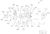
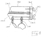
- FIGS. 2 to 8 An alternative embodiment of a gas sampling probe according to the invention is in the FIGS. 2 to 8 shown.
- FIGS. 2 to 8 an embodiment of a device 100, which includes two gas sampling probes 110, 210.
- the two gas sampling probes 110, 210 are constructed essentially identically and are arranged parallel to one another in the device 100. This redundant construction of two gas sampling probes 110, 210 serves to compare the measurement results obtained by the respective gas sampling probes 110, 210 with one another and thereby to be able to estimate their informative value.
- the gas sampling probe 101 comprises a gas line 110, which comprises three sections 110.1, 110.2, 110.3.
- the section 110.1 is formed as a cylindrical tube made of a temperature and corrosion-resistant steel.
- the section 110.2 is designed as a glass tube made of laboratory glass.
- the section 110.3 is formed as a multi-angled metal tube, which extends partially in the cover 301 of a cover 300 explained in more detail below.
- an adsorption material 120 is arranged in the form of Kohlegries.
- a needle valve 130 is arranged between the section 110.1 of the gas line 110 and the section 110.2 of the gas line 110.
- the portion 110.1 is inserted into a connecting means 116, which is fluidically coupled to the needle valve 130.
- the section 110.1 is sealed by rubber O-rings against the connecting means 116.
- the portion 110.2 is inserted into a connecting means 117, which is also fluidly coupled to the needle valve 130.
- the section 110.2 is sealed in accordance with O-rings 111 against the connecting means 117.
- the glass tube 110.2 is largely enveloped by a sheath 300.
- the envelope 300 is formed as a substantially tubular body made of metal and closed on one longitudinal side by a cover 301.
- the casing 300 On the side opposite the lid 301, the casing 300 is fixed to a holding plate 400, which in turn is fastened to a metal plate 500.
- Three resistive heating elements 600 are disposed on the enclosure 300, by the enclosed by the enclosure 300 interior I is heated.
- the portion 110.2 of the gas line 110, in which the adsorption material 120 is arranged which is largely enveloped by the envelope 300, can be heated by the resistance heating elements 600.
- the end of the portion 110.2 which is opposite to the end of this portion 110.2, which is plugged into the connecting means 117, is coupled to the portion 110.3 of the gas line 110.
- the connection to this section 110.3 of the gas line is formed in the cover 301 of the enclosure 300, in which the connection piece is arranged on this section 110.3 of the gas line 110.
- the cover 301 is screwed by wing screws 302 to the enclosure 300. In the screwed-on state of the cover 301, the section 110.2 is thereby fluidly connected to the section 110.3 of the gas line 110 via the connection formed in the cover 301.
- the gas sampling probe 110 further comprises a fastening means 700 for attaching the gas sampling probe 101 to a wall of a gas container.
- This fastener 700 is formed in the form of a Flanschblattes, which is screwed to an angled portion 501 of the sheet 500. In this case, the section 110.1 of the gas line 110 is guided through this flange plate 700.
- the section 110.1 has a gas inlet 116.
- the gas inlet 116 opens into the gas channel 115, which is formed in the gas line 110.
- the sections 110.1, 110.2, 110.3 of the gas line 110 fluidly connected to each other in such a way that they form a total of the gas passage 115.
- the gas sampling probe 201 is constructed accordingly and comprises a gas line 210 with the three sections 210.1, 210.2, 210.3.
- the section 210.1 is coupled to the valve 230 via a connection means 216 and the section 210.2 is also coupled to the valve 230 via the connection means 217.
- the envelope 300 likewise encompasses the section 210.2 of the gas line 210 in the form of a glass tube, in which the adsorption material 220 is arranged.
- the section 210.1 is guided in a corresponding manner through the flange leaf 701 and has at its free end a gas inlet 216 in the gas channel 215 formed in the gas line 210.
- the flange sheet 700 can be arranged on a flange sheet 701, which is arranged on the wall of a gas container, for forming a flange connection of the flange leaves 700, 701.
- the sections 110.1, 210.1 of the gas lines 110, 210 of the gas sampling probes 101, 201, at which the respective gas inlet 116, 216 is arranged are arranged in the gas which is enclosed by the wall of the gas container , At the same time, the remaining components of the gas sampling probes 101, 201 are arranged outside the gas container.
- gas pumps can be connected to the sections 110.3, 210.3 of the gas lines 110, 210, as explained above, in order to be able to pass gas through the gas inlets 116, 216 into the gas lines 110, 210 and through the respective gas channels 115, 215.
- the portions 110.2, 210.2 of the gas conduits 110, 210 formed as glass tubes are removably formed in the respective gas conduits 110, 210.
- the cover 301 is released from the enclosure 300 by loosening the wing screws 302. Subsequently, the glass tubes 110.2, 210.2 can be pulled out of the connection means 117, 217.
- the adsorption material 120, 220 arranged in the glass tubes 110.2, 210.2 can subsequently be analyzed.
Landscapes
- Life Sciences & Earth Sciences (AREA)
- Health & Medical Sciences (AREA)
- General Health & Medical Sciences (AREA)
- Chemical & Material Sciences (AREA)
- Analytical Chemistry (AREA)
- Biochemistry (AREA)
- Physics & Mathematics (AREA)
- General Physics & Mathematics (AREA)
- Immunology (AREA)
- Pathology (AREA)
- Engineering & Computer Science (AREA)
- Biomedical Technology (AREA)
- Molecular Biology (AREA)
- Sampling And Sample Adjustment (AREA)
Priority Applications (2)
| Application Number | Priority Date | Filing Date | Title |
|---|---|---|---|
| EP23155163.1A EP4198485B1 (fr) | 2017-03-20 | 2017-03-20 | Procédé de prélèvement d'un échantillon de gaz à l'aide d'une sonde de prélèvement de gaz et de réalisation d'un contrôle d'étanchéité d'un canal gazeux de la sonde de prélèvement de gaz |
| EP17161873.9A EP3379228B1 (fr) | 2017-03-20 | 2017-03-20 | Sonde de prélèvement de gaz, récipient de gaz comprenant une telle sonde de prélèvement de gaz et procédé de prélèvement d'un échantillon gazeux à l'aide d'une telle sonde |
Applications Claiming Priority (1)
| Application Number | Priority Date | Filing Date | Title |
|---|---|---|---|
| EP17161873.9A EP3379228B1 (fr) | 2017-03-20 | 2017-03-20 | Sonde de prélèvement de gaz, récipient de gaz comprenant une telle sonde de prélèvement de gaz et procédé de prélèvement d'un échantillon gazeux à l'aide d'une telle sonde |
Related Child Applications (2)
| Application Number | Title | Priority Date | Filing Date |
|---|---|---|---|
| EP23155163.1A Division EP4198485B1 (fr) | 2017-03-20 | 2017-03-20 | Procédé de prélèvement d'un échantillon de gaz à l'aide d'une sonde de prélèvement de gaz et de réalisation d'un contrôle d'étanchéité d'un canal gazeux de la sonde de prélèvement de gaz |
| EP23155163.1A Division-Into EP4198485B1 (fr) | 2017-03-20 | 2017-03-20 | Procédé de prélèvement d'un échantillon de gaz à l'aide d'une sonde de prélèvement de gaz et de réalisation d'un contrôle d'étanchéité d'un canal gazeux de la sonde de prélèvement de gaz |
Publications (3)
| Publication Number | Publication Date |
|---|---|
| EP3379228A1 true EP3379228A1 (fr) | 2018-09-26 |
| EP3379228B1 EP3379228B1 (fr) | 2023-06-07 |
| EP3379228C0 EP3379228C0 (fr) | 2023-06-07 |
Family
ID=58412880
Family Applications (2)
| Application Number | Title | Priority Date | Filing Date |
|---|---|---|---|
| EP17161873.9A Active EP3379228B1 (fr) | 2017-03-20 | 2017-03-20 | Sonde de prélèvement de gaz, récipient de gaz comprenant une telle sonde de prélèvement de gaz et procédé de prélèvement d'un échantillon gazeux à l'aide d'une telle sonde |
| EP23155163.1A Active EP4198485B1 (fr) | 2017-03-20 | 2017-03-20 | Procédé de prélèvement d'un échantillon de gaz à l'aide d'une sonde de prélèvement de gaz et de réalisation d'un contrôle d'étanchéité d'un canal gazeux de la sonde de prélèvement de gaz |
Family Applications After (1)
| Application Number | Title | Priority Date | Filing Date |
|---|---|---|---|
| EP23155163.1A Active EP4198485B1 (fr) | 2017-03-20 | 2017-03-20 | Procédé de prélèvement d'un échantillon de gaz à l'aide d'une sonde de prélèvement de gaz et de réalisation d'un contrôle d'étanchéité d'un canal gazeux de la sonde de prélèvement de gaz |
Country Status (1)
| Country | Link |
|---|---|
| EP (2) | EP3379228B1 (fr) |
Cited By (4)
| Publication number | Priority date | Publication date | Assignee | Title |
|---|---|---|---|---|
| DE102020113180A1 (de) | 2020-05-15 | 2021-11-18 | Iav Gmbh Ingenieurgesellschaft Auto Und Verkehr | Vorrichtung zur Probennahme aus einem Abgasmassenstrom |
| CN115014884A (zh) * | 2022-07-15 | 2022-09-06 | 南通东昌环保设备科技有限公司 | 一种环境质量检测设备 |
| US20240280444A1 (en) * | 2023-02-22 | 2024-08-22 | Kimberly Lynn Kanapeckas Metris | Fluid sampling method and apparatus |
| EP4455632A4 (fr) * | 2021-12-24 | 2025-04-09 | Nuctech Company Limited | Dispositif d'échantillonnage de gaz à l'état de trace et système de détection |
Citations (6)
| Publication number | Priority date | Publication date | Assignee | Title |
|---|---|---|---|---|
| US5142143A (en) * | 1990-10-31 | 1992-08-25 | Extrel Corporation | Method and apparatus for preconcentration for analysis purposes of trace constitutes in gases |
| EP1324034A1 (fr) * | 2000-09-08 | 2003-07-02 | Central Research Institute of Electric Power Industry | Procede et dispositif d'analyse fractionnelle continue de mercure metallique et de mercure hydrosoluble contenus dans un gaz |
| US20050084976A1 (en) * | 2003-10-20 | 2005-04-21 | Tom Baldwin | Filter for determination of mercury in exhaust gases |
| US20120261569A1 (en) * | 2009-12-21 | 2012-10-18 | Inficon Gmbh | Method and device for determining leakage |
| US20120270334A1 (en) * | 2009-08-27 | 2012-10-25 | 1St Detect Corporation | Preconcentrating a sample |
| CN103149059A (zh) * | 2013-02-01 | 2013-06-12 | 天津市环境监测中心 | 一种双通道气态汞烟气采样系统 |
Family Cites Families (2)
| Publication number | Priority date | Publication date | Assignee | Title |
|---|---|---|---|---|
| FR2919055B1 (fr) * | 2007-07-17 | 2009-10-16 | Inst Francais Du Petrole | Procede et dispositif de detection et de quantification d'un compose chimique dans un courant fluide |
| US20090084199A1 (en) * | 2007-09-28 | 2009-04-02 | Wright James E | Quick-change sorbent trap module and method |
-
2017
- 2017-03-20 EP EP17161873.9A patent/EP3379228B1/fr active Active
- 2017-03-20 EP EP23155163.1A patent/EP4198485B1/fr active Active
Patent Citations (6)
| Publication number | Priority date | Publication date | Assignee | Title |
|---|---|---|---|---|
| US5142143A (en) * | 1990-10-31 | 1992-08-25 | Extrel Corporation | Method and apparatus for preconcentration for analysis purposes of trace constitutes in gases |
| EP1324034A1 (fr) * | 2000-09-08 | 2003-07-02 | Central Research Institute of Electric Power Industry | Procede et dispositif d'analyse fractionnelle continue de mercure metallique et de mercure hydrosoluble contenus dans un gaz |
| US20050084976A1 (en) * | 2003-10-20 | 2005-04-21 | Tom Baldwin | Filter for determination of mercury in exhaust gases |
| US20120270334A1 (en) * | 2009-08-27 | 2012-10-25 | 1St Detect Corporation | Preconcentrating a sample |
| US20120261569A1 (en) * | 2009-12-21 | 2012-10-18 | Inficon Gmbh | Method and device for determining leakage |
| CN103149059A (zh) * | 2013-02-01 | 2013-06-12 | 天津市环境监测中心 | 一种双通道气态汞烟气采样系统 |
Cited By (6)
| Publication number | Priority date | Publication date | Assignee | Title |
|---|---|---|---|---|
| DE102020113180A1 (de) | 2020-05-15 | 2021-11-18 | Iav Gmbh Ingenieurgesellschaft Auto Und Verkehr | Vorrichtung zur Probennahme aus einem Abgasmassenstrom |
| DE102020113180B4 (de) * | 2020-05-15 | 2025-11-06 | Iav Gmbh Ingenieurgesellschaft Auto Und Verkehr | Vorrichtung zur Probennahme aus einem Abgasmassenstrom |
| EP4455632A4 (fr) * | 2021-12-24 | 2025-04-09 | Nuctech Company Limited | Dispositif d'échantillonnage de gaz à l'état de trace et système de détection |
| CN115014884A (zh) * | 2022-07-15 | 2022-09-06 | 南通东昌环保设备科技有限公司 | 一种环境质量检测设备 |
| CN115014884B (zh) * | 2022-07-15 | 2023-10-03 | 南通东昌环保设备科技有限公司 | 一种环境质量检测设备 |
| US20240280444A1 (en) * | 2023-02-22 | 2024-08-22 | Kimberly Lynn Kanapeckas Metris | Fluid sampling method and apparatus |
Also Published As
| Publication number | Publication date |
|---|---|
| EP4198485A1 (fr) | 2023-06-21 |
| EP4198485B1 (fr) | 2026-04-15 |
| EP3379228B1 (fr) | 2023-06-07 |
| EP3379228C0 (fr) | 2023-06-07 |
Similar Documents
| Publication | Publication Date | Title |
|---|---|---|
| EP3379228B1 (fr) | Sonde de prélèvement de gaz, récipient de gaz comprenant une telle sonde de prélèvement de gaz et procédé de prélèvement d'un échantillon gazeux à l'aide d'une telle sonde | |
| EP0491000B1 (fr) | Procede et dispositif pour la preparation d'un melange gazeux a des fins d'analyse et application du procede | |
| DE102009043236A1 (de) | Multifunktions-Steuerventil für Gasmessgeräte | |
| DE19848542A1 (de) | Sonde | |
| DE2747619C3 (fr) | ||
| DE102012223390B4 (de) | Mobile Korrosions- und Materialprüfeinrichtung für Korrosions- und Scalinguntersuchungen | |
| DE10325702B3 (de) | Abgasmessvorrichtung | |
| WO2001090718A1 (fr) | Procede et dispositif pour determiner la concentration d'analytes | |
| EP3757571B1 (fr) | Unité d'essai d'écoulement, ensemble et utilisation d'une unité d'essai d'écoulement pour mettre en uvre une réaction de détection | |
| DE102011105486A1 (de) | Verfahren zur Langzeitmessung der Exhalationsrates einer gasförmigen Substanz und Vorrichtung zur Durchführung | |
| DE102010010112A1 (de) | Vorrichtung zur selektiven Bestimmung der Menge von Ölnebel oder Aerosolen | |
| DE3932202C2 (fr) | ||
| DE19543056A1 (de) | Verfahren und Vorrichtung zur Ermittlung der Standzeit von Gasfiltern für Atemschutzgeräte | |
| EP0012945B1 (fr) | Procédé de mesure de l'émission de composés gazeux inorganiques fluorés ou chlorés | |
| DE102013223891B4 (de) | Kartuschendepositionssammler und Verfahren zur Eintragsmessung atmospärischer Stoffe | |
| CH655798A5 (de) | Probenwechsler fuer gaschromatographische analysenapparate. | |
| EP1963818A1 (fr) | Dispositif d'etude de permeation ou de passage de matiere | |
| DE102004053430A1 (de) | Verfahren und Vorrichtung zur Ölverbrauchsbestimmung eines Verbrennungsmotors | |
| DE19713469C1 (de) | Gerät zur Analyse von Gasgemischen | |
| EP2881723A2 (fr) | Appareil de vérification pour vêtement de protection | |
| DE10114135C2 (de) | Verfahren und Messanordnung zur Untersuchung des Kohlendioxidgehalts in Wasser | |
| DE102022108087A1 (de) | Analysevorrichtung mit separater und außenliegender Probenaufnahmevorrichtung | |
| AT503136A4 (de) | Kammer zur messung von verdunstungs- und/oder verdampfungsemissionen eines objekts | |
| DE4416203C2 (de) | Einrichtung zum Bestimmen von Schadstoffen in einem flüssigen Brennstoff | |
| DE2236972C3 (de) | Apparatur zum Gewinnen von Proben der Abgase von mit innerer Verbrennung arbeitenden Triebwerken |
Legal Events
| Date | Code | Title | Description |
|---|---|---|---|
| PUAI | Public reference made under article 153(3) epc to a published international application that has entered the european phase |
Free format text: ORIGINAL CODE: 0009012 |
|
| STAA | Information on the status of an ep patent application or granted ep patent |
Free format text: STATUS: REQUEST FOR EXAMINATION WAS MADE |
|
| 17P | Request for examination filed |
Effective date: 20180129 |
|
| AK | Designated contracting states |
Kind code of ref document: A1 Designated state(s): AL AT BE BG CH CY CZ DE DK EE ES FI FR GB GR HR HU IE IS IT LI LT LU LV MC MK MT NL NO PL PT RO RS SE SI SK SM TR |
|
| AX | Request for extension of the european patent |
Extension state: BA ME |
|
| RBV | Designated contracting states (corrected) |
Designated state(s): AL AT BE BG CH CY CZ DE DK EE ES FI FR GB GR HR HU IE IS IT LI LT LU LV MC MK MT NL NO PL PT RO RS SE SI SK SM TR |
|
| STAA | Information on the status of an ep patent application or granted ep patent |
Free format text: STATUS: EXAMINATION IS IN PROGRESS |
|
| 17Q | First examination report despatched |
Effective date: 20190703 |
|
| GRAP | Despatch of communication of intention to grant a patent |
Free format text: ORIGINAL CODE: EPIDOSNIGR1 |
|
| STAA | Information on the status of an ep patent application or granted ep patent |
Free format text: STATUS: GRANT OF PATENT IS INTENDED |
|
| INTG | Intention to grant announced |
Effective date: 20220622 |
|
| GRAJ | Information related to disapproval of communication of intention to grant by the applicant or resumption of examination proceedings by the epo deleted |
Free format text: ORIGINAL CODE: EPIDOSDIGR1 |
|
| STAA | Information on the status of an ep patent application or granted ep patent |
Free format text: STATUS: EXAMINATION IS IN PROGRESS |
|
| GRAP | Despatch of communication of intention to grant a patent |
Free format text: ORIGINAL CODE: EPIDOSNIGR1 |
|
| STAA | Information on the status of an ep patent application or granted ep patent |
Free format text: STATUS: GRANT OF PATENT IS INTENDED |
|
| INTG | Intention to grant announced |
Effective date: 20221104 |
|
| GRAS | Grant fee paid |
Free format text: ORIGINAL CODE: EPIDOSNIGR3 |
|
| GRAA | (expected) grant |
Free format text: ORIGINAL CODE: 0009210 |
|
| STAA | Information on the status of an ep patent application or granted ep patent |
Free format text: STATUS: THE PATENT HAS BEEN GRANTED |
|
| AK | Designated contracting states |
Kind code of ref document: B1 Designated state(s): AL AT BE BG CH CY CZ DE DK EE ES FI FR GB GR HR HU IE IS IT LI LT LU LV MC MK MT NL NO PL PT RO RS SE SI SK SM TR |
|
| REG | Reference to a national code |
Ref country code: GB Ref legal event code: FG4D Free format text: NOT ENGLISH |
|
| REG | Reference to a national code |
Ref country code: CH Ref legal event code: EP Ref country code: AT Ref legal event code: REF Ref document number: 1576475 Country of ref document: AT Kind code of ref document: T Effective date: 20230615 |
|
| REG | Reference to a national code |
Ref country code: DE Ref legal event code: R096 Ref document number: 502017014787 Country of ref document: DE |
|
| U01 | Request for unitary effect filed |
Effective date: 20230620 |
|
| U07 | Unitary effect registered |
Designated state(s): AT BE BG DE DK EE FI FR IT LT LU LV MT NL PT SE SI Effective date: 20230626 |
|
| REG | Reference to a national code |
Ref country code: LT Ref legal event code: MG9D |
|
| PG25 | Lapsed in a contracting state [announced via postgrant information from national office to epo] |
Ref country code: NO Free format text: LAPSE BECAUSE OF FAILURE TO SUBMIT A TRANSLATION OF THE DESCRIPTION OR TO PAY THE FEE WITHIN THE PRESCRIBED TIME-LIMIT Effective date: 20230907 Ref country code: ES Free format text: LAPSE BECAUSE OF FAILURE TO SUBMIT A TRANSLATION OF THE DESCRIPTION OR TO PAY THE FEE WITHIN THE PRESCRIBED TIME-LIMIT Effective date: 20230607 |
|
| PG25 | Lapsed in a contracting state [announced via postgrant information from national office to epo] |
Ref country code: RS Free format text: LAPSE BECAUSE OF FAILURE TO SUBMIT A TRANSLATION OF THE DESCRIPTION OR TO PAY THE FEE WITHIN THE PRESCRIBED TIME-LIMIT Effective date: 20230607 Ref country code: HR Free format text: LAPSE BECAUSE OF FAILURE TO SUBMIT A TRANSLATION OF THE DESCRIPTION OR TO PAY THE FEE WITHIN THE PRESCRIBED TIME-LIMIT Effective date: 20230607 Ref country code: GR Free format text: LAPSE BECAUSE OF FAILURE TO SUBMIT A TRANSLATION OF THE DESCRIPTION OR TO PAY THE FEE WITHIN THE PRESCRIBED TIME-LIMIT Effective date: 20230908 |
|
| PG25 | Lapsed in a contracting state [announced via postgrant information from national office to epo] |
Ref country code: SK Free format text: LAPSE BECAUSE OF FAILURE TO SUBMIT A TRANSLATION OF THE DESCRIPTION OR TO PAY THE FEE WITHIN THE PRESCRIBED TIME-LIMIT Effective date: 20230607 |
|
| PG25 | Lapsed in a contracting state [announced via postgrant information from national office to epo] |
Ref country code: IS Free format text: LAPSE BECAUSE OF FAILURE TO SUBMIT A TRANSLATION OF THE DESCRIPTION OR TO PAY THE FEE WITHIN THE PRESCRIBED TIME-LIMIT Effective date: 20231007 |
|
| PG25 | Lapsed in a contracting state [announced via postgrant information from national office to epo] |
Ref country code: SM Free format text: LAPSE BECAUSE OF FAILURE TO SUBMIT A TRANSLATION OF THE DESCRIPTION OR TO PAY THE FEE WITHIN THE PRESCRIBED TIME-LIMIT Effective date: 20230607 Ref country code: SK Free format text: LAPSE BECAUSE OF FAILURE TO SUBMIT A TRANSLATION OF THE DESCRIPTION OR TO PAY THE FEE WITHIN THE PRESCRIBED TIME-LIMIT Effective date: 20230607 Ref country code: RO Free format text: LAPSE BECAUSE OF FAILURE TO SUBMIT A TRANSLATION OF THE DESCRIPTION OR TO PAY THE FEE WITHIN THE PRESCRIBED TIME-LIMIT Effective date: 20230607 Ref country code: IS Free format text: LAPSE BECAUSE OF FAILURE TO SUBMIT A TRANSLATION OF THE DESCRIPTION OR TO PAY THE FEE WITHIN THE PRESCRIBED TIME-LIMIT Effective date: 20231007 Ref country code: CZ Free format text: LAPSE BECAUSE OF FAILURE TO SUBMIT A TRANSLATION OF THE DESCRIPTION OR TO PAY THE FEE WITHIN THE PRESCRIBED TIME-LIMIT Effective date: 20230607 |
|
| PG25 | Lapsed in a contracting state [announced via postgrant information from national office to epo] |
Ref country code: PL Free format text: LAPSE BECAUSE OF FAILURE TO SUBMIT A TRANSLATION OF THE DESCRIPTION OR TO PAY THE FEE WITHIN THE PRESCRIBED TIME-LIMIT Effective date: 20230607 |
|
| REG | Reference to a national code |
Ref country code: DE Ref legal event code: R097 Ref document number: 502017014787 Country of ref document: DE |
|
| U20 | Renewal fee for the european patent with unitary effect paid |
Year of fee payment: 8 Effective date: 20240214 |
|
| PLBE | No opposition filed within time limit |
Free format text: ORIGINAL CODE: 0009261 |
|
| STAA | Information on the status of an ep patent application or granted ep patent |
Free format text: STATUS: NO OPPOSITION FILED WITHIN TIME LIMIT |
|
| 26N | No opposition filed |
Effective date: 20240308 |
|
| PG25 | Lapsed in a contracting state [announced via postgrant information from national office to epo] |
Ref country code: MC Free format text: LAPSE BECAUSE OF FAILURE TO SUBMIT A TRANSLATION OF THE DESCRIPTION OR TO PAY THE FEE WITHIN THE PRESCRIBED TIME-LIMIT Effective date: 20230607 |
|
| PG25 | Lapsed in a contracting state [announced via postgrant information from national office to epo] |
Ref country code: MC Free format text: LAPSE BECAUSE OF FAILURE TO SUBMIT A TRANSLATION OF THE DESCRIPTION OR TO PAY THE FEE WITHIN THE PRESCRIBED TIME-LIMIT Effective date: 20230607 |
|
| PG25 | Lapsed in a contracting state [announced via postgrant information from national office to epo] |
Ref country code: IE Free format text: LAPSE BECAUSE OF NON-PAYMENT OF DUE FEES Effective date: 20240320 |
|
| PG25 | Lapsed in a contracting state [announced via postgrant information from national office to epo] |
Ref country code: IE Free format text: LAPSE BECAUSE OF NON-PAYMENT OF DUE FEES Effective date: 20240320 |
|
| U20 | Renewal fee for the european patent with unitary effect paid |
Year of fee payment: 9 Effective date: 20250113 |
|
| PGFP | Annual fee paid to national office [announced via postgrant information from national office to epo] |
Ref country code: CH Payment date: 20250401 Year of fee payment: 9 |
|
| PG25 | Lapsed in a contracting state [announced via postgrant information from national office to epo] |
Ref country code: CY Free format text: LAPSE BECAUSE OF FAILURE TO SUBMIT A TRANSLATION OF THE DESCRIPTION OR TO PAY THE FEE WITHIN THE PRESCRIBED TIME-LIMIT; INVALID AB INITIO Effective date: 20170320 |
|
| PG25 | Lapsed in a contracting state [announced via postgrant information from national office to epo] |
Ref country code: HU Free format text: LAPSE BECAUSE OF FAILURE TO SUBMIT A TRANSLATION OF THE DESCRIPTION OR TO PAY THE FEE WITHIN THE PRESCRIBED TIME-LIMIT; INVALID AB INITIO Effective date: 20170320 |
|
| PG25 | Lapsed in a contracting state [announced via postgrant information from national office to epo] |
Ref country code: TR Free format text: LAPSE BECAUSE OF FAILURE TO SUBMIT A TRANSLATION OF THE DESCRIPTION OR TO PAY THE FEE WITHIN THE PRESCRIBED TIME-LIMIT Effective date: 20230607 |
|
| REG | Reference to a national code |
Ref country code: CH Ref legal event code: U11 Free format text: ST27 STATUS EVENT CODE: U-0-0-U10-U11 (AS PROVIDED BY THE NATIONAL OFFICE) Effective date: 20260401 |
|
| PGFP | Annual fee paid to national office [announced via postgrant information from national office to epo] |
Ref country code: GB Payment date: 20260324 Year of fee payment: 10 |
|
| U20 | Renewal fee for the european patent with unitary effect paid |
Year of fee payment: 10 Effective date: 20260311 |