EP3379307A1 - Dispositif d'alignement et procédé d'alignement - Google Patents
Dispositif d'alignement et procédé d'alignement Download PDFInfo
- Publication number
- EP3379307A1 EP3379307A1 EP16888211.6A EP16888211A EP3379307A1 EP 3379307 A1 EP3379307 A1 EP 3379307A1 EP 16888211 A EP16888211 A EP 16888211A EP 3379307 A1 EP3379307 A1 EP 3379307A1
- Authority
- EP
- European Patent Office
- Prior art keywords
- optical fiber
- side image
- luminances
- core optical
- axis direction
- Prior art date
- Legal status (The legal status is an assumption and is not a legal conclusion. Google has not performed a legal analysis and makes no representation as to the accuracy of the status listed.)
- Granted
Links
Images




Classifications
-
- G—PHYSICS
- G02—OPTICS
- G02B—OPTICAL ELEMENTS, SYSTEMS OR APPARATUS
- G02B6/00—Light guides; Structural details of arrangements comprising light guides and other optical elements, e.g. couplings
- G02B6/24—Coupling light guides
- G02B6/255—Splicing of light guides, e.g. by fusion or bonding
- G02B6/2555—Alignment or adjustment devices for aligning prior to splicing
-
- G—PHYSICS
- G01—MEASURING; TESTING
- G01B—MEASURING LENGTH, THICKNESS OR SIMILAR LINEAR DIMENSIONS; MEASURING ANGLES; MEASURING AREAS; MEASURING IRREGULARITIES OF SURFACES OR CONTOURS
- G01B11/00—Measuring arrangements characterised by the use of optical techniques
- G01B11/26—Measuring arrangements characterised by the use of optical techniques for measuring angles or tapers; for testing the alignment of axes
- G01B11/27—Measuring arrangements characterised by the use of optical techniques for measuring angles or tapers; for testing the alignment of axes for testing the alignment of axes
-
- G—PHYSICS
- G02—OPTICS
- G02B—OPTICAL ELEMENTS, SYSTEMS OR APPARATUS
- G02B6/00—Light guides; Structural details of arrangements comprising light guides and other optical elements, e.g. couplings
- G02B6/02—Optical fibres with cladding with or without a coating
- G02B6/02042—Multicore optical fibres
-
- G—PHYSICS
- G02—OPTICS
- G02B—OPTICAL ELEMENTS, SYSTEMS OR APPARATUS
- G02B6/00—Light guides; Structural details of arrangements comprising light guides and other optical elements, e.g. couplings
- G02B6/24—Coupling light guides
- G02B6/36—Mechanical coupling means
- G02B6/38—Mechanical coupling means having fibre to fibre mating means
- G02B6/3807—Dismountable connectors, i.e. comprising plugs
- G02B6/3833—Details of mounting fibres in ferrules; Assembly methods; Manufacture
- G02B6/3834—Means for centering or aligning the light guide within the ferrule
- G02B6/3843—Means for centering or aligning the light guide within the ferrule with auxiliary facilities for movably aligning or adjusting the fibre within its ferrule, e.g. measuring position or eccentricity
-
- G—PHYSICS
- G02—OPTICS
- G02B—OPTICAL ELEMENTS, SYSTEMS OR APPARATUS
- G02B6/00—Light guides; Structural details of arrangements comprising light guides and other optical elements, e.g. couplings
- G02B6/24—Coupling light guides
- G02B6/36—Mechanical coupling means
- G02B6/38—Mechanical coupling means having fibre to fibre mating means
- G02B6/3807—Dismountable connectors, i.e. comprising plugs
- G02B6/3873—Connectors using guide surfaces for aligning ferrule ends, e.g. tubes, sleeves, V-grooves, rods, pins, balls
- G02B6/3885—Multicore or multichannel optical connectors, i.e. one single ferrule containing more than one fibre, e.g. ribbon type
-
- G—PHYSICS
- G02—OPTICS
- G02B—OPTICAL ELEMENTS, SYSTEMS OR APPARATUS
- G02B6/00—Light guides; Structural details of arrangements comprising light guides and other optical elements, e.g. couplings
- G02B6/24—Coupling light guides
- G02B6/42—Coupling light guides with opto-electronic elements
- G02B6/4201—Packages, e.g. shape, construction, internal or external details
- G02B6/4219—Mechanical fixtures for holding or positioning the elements relative to each other in the couplings; Alignment methods for the elements, e.g. measuring or observing methods especially used therefor
- G02B6/422—Active alignment, i.e. moving the elements in response to the detected degree of coupling or position of the elements
- G02B6/4221—Active alignment, i.e. moving the elements in response to the detected degree of coupling or position of the elements involving a visual detection of the position of the elements, e.g. by using a microscope or a camera
-
- G—PHYSICS
- G01—MEASURING; TESTING
- G01B—MEASURING LENGTH, THICKNESS OR SIMILAR LINEAR DIMENSIONS; MEASURING ANGLES; MEASURING AREAS; MEASURING IRREGULARITIES OF SURFACES OR CONTOURS
- G01B11/00—Measuring arrangements characterised by the use of optical techniques
- G01B11/002—Measuring arrangements characterised by the use of optical techniques for measuring two or more coordinates
Definitions
- the embodiments of the present invention relate to an alignment apparatus that aligns an optical fiber, and an alignment method.
- An alignment apparatus that aligns an optical fiber needs to not only perform alignment in the horizontal and vertical directions of a cross section of the optical fiber, but also align a rotation angle whose central axis is the longitudinal direction of the optical fiber.
- some alignment apparatuses use active alignment, and some alignment apparatuses use passive alignment.
- Some alignment apparatuses using passive alignment perform alignment by observing an end face of an optical fiber, or by observing a side of an optical fiber by use of two markers on the orthogonal axis of the optical fiber.
- an alignment apparatus using active alignment is not suitable for work in a field, because a location where optical fibers are connected is apart from a location where power is monitored.
- An alignment apparatus that performs alignment by observing an end face of an optical fiber needs a complicated optical system such as a mirror for accurate core positioning.
- An alignment apparatus that performs alignment by observing a side of an optical fiber by use of two markers needs two types of different hole markers; an influence on connection characteristics of the hole markers is not clear.
- an alignment apparatus that can efficiently align an optical fiber, and an alignment method will be provided.
- the acquisition unit acquires one or more side images of the optical fiber.
- the calculation unit calculates correlation coefficients between the luminances of the one or more side images and those of one or more reference side images.
- the rotation processing unit rotates the optical fiber in the axis direction of the optical fiber so that the correlation coefficients peak.
- the alignment apparatus can align a rotation angle of an optical fiber on the basis of side images of the optical fiber, and reference side images. As a result, the alignment apparatus can efficiently align a rotation angle of the optical fiber.
- the alignment apparatus aligns a rotation angle of an optical fiber.
- the alignment apparatus rotatably retains an optical fiber, and, in the longitudinal direction of the optical fiber (direction where the optical fiber extends), fixes a different optical fiber from the aforementioned optical fiber.
- the alignment apparatus rotates the former optical fiber, and fixes it in the position of aligning with the latter optical fiber.
- FIG. 1 shows a configuration example of an alignment apparatus 1 according to the first embodiment.
- the alignment apparatus 1 aligns an optical fiber 2a with an optical fiber 2b.
- the optical fibers 2a and 2b are, for example, multi-core fibers each of which has a plurality of cores in its cladding.
- the optical fibers 2a and 2b are, for example, four-core fibers or eight-core fibers.
- the configurations of the optical fibers 2a and 2b are not restricted to particular configurations.
- the alignment apparatus 1 comprises a control unit 10, a photographing unit 20, grippers 30 and 40, etc.
- the control unit 10 controls the whole of the alignment apparatus 1.
- the control unit 10 aligns the optical fiber 2a on the basis of images photographed by the photographing unit 20.
- the control unit 10 is comprised by a CPU, a ROM, a RAM, an NVM, and an interface, for example.
- the control unit 10 may be a desktop PC, a notebook PC, or a tablet PC, for example.
- control unit 10 can be achieved by execution of a program by the CPU, for example. That is, the program is used for a computer that operates as at least a part of the alignment apparatus 1.
- control unit 10 The functions of the control unit 10 will be described later.
- the photographing unit 20 photographs side images of the optical fibers 2a and 2b.
- the photographing unit 20 is set in the vicinity of the position where an end face of the optical fiber 2a and an end face of the optical fiber 2b face each other, and photographs a side of the optical fiber 2a and a side of the optical fiber 2b at the same time, for example.
- the photographing unit 20 is comprised by a CCD, etc., for example.
- the photographing unit 20 photographs side images by use of visible light or invisible light.
- the photographing unit 20 transmits the photographed images to the control unit 10.
- the photographing unit 20 photographs the optical fibers 2a and 2b on two sides.
- the photographing unit 20 photographs the optical fibers 2a and 2b in two directions orthogonal to each other, for example.
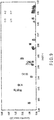
- FIG. 2 shows an example of side images photographed by the photographing unit 20.
- the horizontal and vertical directions are determined to be the X-axis direction and the Y-axis direction, respectively.
- the photographing unit 20 photographs side images in the X-axis direction, and side images in the Y-axis direction.
- the photographing unit 20 is composed by, for example, a camera that photographs the optical fibers 2a and 2b in the X-axis direction (first direction), and a camera that photographs the optical fibers 2a and 2b in the Y-axis direction (second direction).
- the gripper 30 grips the optical fiber 2a.
- the gripper 30 is comprised by a fiber holder in which V grooves are formed, etc., for example.
- the gripper 30 retains the optical fiber 2a by the fiber holder, etc.
- the gripper 30 rotates the optical fiber 2a in the axis direction of the optical fiber 2a on the basis of a signal from the control unit 10.
- the gripper 30 comprises a driving unit, etc., and rotates the optical fiber 2a by transmitting motive power from the driving unit to the fiber holder, for example.
- the gripper 40 grips the optical fiber 2b.
- the gripper 40 is comprised by a fiber holder in which V grooves are formed, etc., for example.
- the gripper 40 retains the optical fiber 2b by the fiber holder, etc.
- control unit 10 Next, the functions achieved by the control unit 10 will be described.
- FIG. 3 is a figure for describing the functions achieved by the control unit 10.
- control unit 10 has the function of acquiring side images of the optical fiber 2a, and side images (reference side images) of the optical fiber 2b (acquisition unit) .
- the control unit 10 acquires an image in the X-axis direction, and an image in the Y-axis direction from the photographing unit 20.
- the control unit 10 may transmit a signal for photographing images to the photographing unit 20, and receive an image in the X-axis direction, and an image in the Y-axis direction from the photographing unit 20, for example.
- the control unit 10 may acquire an image in the X-axis direction, and an image in the Y-axis direction transmitted from the photographing unit 20 with a predetermined timing.
- the control unit 10 extracts a side image (first side image) of the optical fiber 2a and a side image (first reference side image) of the optical fiber 2b from an image in the X-axis direction.
- the control unit 10 extracts a side image (second side image) of the optical fiber 2a and a side image (second reference side image) of the optical fiber 2b from an image in the Y-axis direction.
- the control unit 10 has the function of calculating correlation coefficients on the basis of the luminances of side images of the optical fiber 2a and those of side images of the optical fiber 2b (calculation unit). That is, the control unit 10 calculates a correlation coefficient between the luminances of the optical fiber 2a and those of the optical fiber 2b in the X-axis direction, and calculates a correlation coefficient between the luminances of the optical fiber 2a and those of the optical fiber 2b in the Y-axis direction.
- the control unit 10 averages the luminances of side images of the optical fiber 2a along the longitudinal direction of the optical fiber 2a, for example. That is, the control unit 10 acquires a luminance string of the optical fiber 2a in the longitudinal direction, and averages the luminance string. The control unit 10 acquires the average value of the luminance string as an average luminance of the pixel value of the string (i.e., pixel value in the axis orthogonal to the longitudinal direction in the side images) .
- control unit 10 acquires average luminances of side images of the optical fiber 2b.
- the control unit 10 calculates a correlation coefficient ZNCC according to equation 1 given below, for example.
- L(i), R(i), and M respectively indicate the i-th average luminance of the optical fiber 2a, the i-th average luminance of the optical fiber 2b, and the total number of pixels.
- L indicates the average value of L(i).
- R indicates the average value of R(i).
- a correlation coefficient (first correlation coefficient) calculated from side images in the X-axis direction is determined to be a ZNCC-X
- a correlation coefficient (second correlation coefficient) calculated from side images in the Y-axis direction is determined to be a ZNCC-Y.
- the control unit 10 has the function of rotating the optical fiber 2a in the axis direction of the optical fiber 2a so that correlation coefficients peak (rotation processing unit).
- a rotation angle is an angle at which the optical fiber 2a rotates in the axis direction of the optical fiber 2a from an initial position.
- the control unit 10 once calculating correlation coefficients ZNCCs, rotates the optical fiber 2a through the gripper 30, for example.
- the control unit 10 once again calculates correlation coefficients ZNCCs.
- the control unit 10 repeats such operations, and pinpoints the peak of correlation coefficients ZNCCs.
- the control unit 10 determines a rotation angle at which a ZNCC-X and a ZNCC-Y get peak values, within the scope of the ZNCC-X and the ZNCC-Y each of which exceeds a predetermined threshold, to be a rotation angle at which correlation coefficients peak, for example.
- control unit 10 Next, an operation example of the control unit 10 will be described.
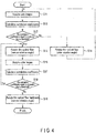
- FIG. 4 is a flowchart for describing an operation example of the control unit 10.
- the optical fiber 2a is set in the gripper 30, and the optical fiber 2b is set in the gripper 40.
- control unit 10 acquires side images from the photographing unit 20 (S11). That is, the control unit 10 acquires side images of the optical fibers 2a and 2b in the X-axis direction, and side images of the optical fibers 2a and 2b in the Y-axis direction.
- control unit 10 calculates correlation coefficients ZNCCs on the basis of the side images (S12). That is, the control unit 10 calculates a ZNCC-X and a ZNCC-Y.
- the control unit 10 determines if the correlation coefficients ZNCCs are equal to or greater than a predetermined threshold (S13). That is, the control unit 10 determines if the ZNCC-X is equal to or greater than a predetermined threshold, and the ZNCC-Y is equal to or greater than a predetermined threshold.
- the control unit 10 rotates the optical fiber 2a at a relatively wide angle (S14). Upon rotating the optical fiber 2a at a relatively wide angle, the control unit 10 returns to S11.
- the control unit 10 rotates the optical fiber 2a at a relatively narrow angle (S15). Upon rotating the optical fiber 2a at a relatively narrow angle, the control unit 10 acquires side images from the photographing unit 20 (S16). Once the side images are acquired, the control unit 10 calculates correlation coefficients ZNCCs on the basis of the side images (S17).
- the control unit 10 determines if the correlation coefficients ZNCCs are equal to or greater than the preceding correlation coefficients ZNCCs (i.e., correlation coefficients ZNCCs at the preceding rotation angle) (S18).
- the control unit 10 may determine if a ZNCC-X is equal to or greater than a preceding ZNCC-X, and a ZNCC-Y is equal to or greater than a preceding ZNCC-Y, for example.
- the control unit 10 may determine if at least one of a ZNCC-X and a ZNCC-Y is equal to or greater than a preceding ZNCC-X or ZNCC-Y.
- the control unit 10 Upon determining that the correlation coefficients ZNCCs are not equal to or greater than the preceding correlation coefficients ZNCCs (S18, NO), the control unit 10 returns to S15.
- the control unit 10 rotates the optical fiber 2a backward at an angle that cancels the rotation in S15 (S19).
- control unit 10 finishes the operations.
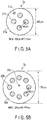
- FIGS. 5 show examples of section views of the optical fiber 2.
- optical fiber 2 is a four-core fiber or an eight-core fiber.
- FIG. 5 (a) shows an example of a section view when the optical fiber 2 is a four-core fiber.
- the optical fiber 2 is comprised by a circular cladding 21a, four cores 21b, a marker 21c, etc.
- the four cores 21b are formed in positions that are symmetric to one another with respect to the central portion of the cladding 21a.
- the marker 21c is comprised by a material whose refractive index is lower than the cladding 21a.
- the marker 21c may be a hole.
- the marker 21c is formed further to an outer side than the four cores 21b.
- the core gap, the cladding, and the mode field diameter in a wavelength of 1310 nm are 40 ⁇ m, 125 ⁇ m, and 8.6 ⁇ m, respectively.
- FIG. 5 (b) shows an example of a section view when the optical fiber 2 is an eight-core fiber.
- the optical fiber 2 is comprised by a circular cladding 22a, eight cores 22b, a marker 22c, etc.
- the eight cores 22b are formed in positions that are symmetric to one another with respect to the central portion of the cladding 22a.
- the marker 22c is comprised by a material whose refractive index is lower than the cladding 22a.
- the marker 22c may be a hole.
- the marker 22c is formed further to an inner side than the four cores 22b.
- the core gap, the cladding, and the mode field diameter in a wavelength of 1310 nm are 40 ⁇ m, 175 ⁇ m, and 8.6 ⁇ m, respectively.
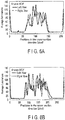
- FIGS. 6 are graphs showing the relationships between average luminances and pixel values in the X-axis direction at predetermined rotation angles.
- the horizontal axes indicate positions (pixel values) in the cross-section direction, and the vertical axes indicate average luminance values.
- the solid lines indicate the average luminances of the optical fiber 2a.
- the broken lines indicate the average luminances of the optical fiber 2b.
- FIG. 6 (a) shows an example when the optical fiber 2 is a four-core fiber (case of FIG. 5 (a) ).
- FIG. 6 (b) shows an example when the optical fiber 2 is an eight-core fiber (case of FIG. 5 (b) ).
- FIG. 6 (c) shows an example when the optical fiber 2 is a single-mode fiber.
- the ZNCC-Xs in FIGS. 6 (a), 6(b) , and 6(c) are 0.848, 0.847, and 0.999, respectively.
- FIG. 7 is a graph showing the relationships between rotation angles, and correlation coefficients obtainable from side images in the X-axis direction.
- the horizontal axis indicates rotation angles of the optical fiber 2a
- the vertical axis indicates ZNCC-Xs.
- the plotted circles indicate ZNCC-Xs when the optical fiber 2 is a four-core fiber.
- the plotted triangles indicate ZNCC-Xs when the optical fiber 2 is an eight-core fiber.
- the plotted squares indicate ZNCC-Xs when the optical fiber 2 is a single-mode fiber.
- the optical fiber 2 when the optical fiber 2 is a four-core fiber, there are four peaks at 90-degree intervals at rotation angles of 0 to 360 degrees.
- the number of peaks, and intervals correspond to the number of cores, and disposition of the optical fiber 2.
- the peak values of ZNCC-Xs are 0.994, 0.990, 0.990, and 0.993 in the order of angle from narrowest to widest.
- the peak value around 60 degrees is the highest.
- the marker 21c of the optical fiber 2a and the marker 21c of the optical fiber 2b are correspondent. Accordingly, it has turned out that when there is a marker more to an outer side than the cores, it is possible to align a rotation angle as well as the marker.
- the optical fiber 2 when the optical fiber 2 is an eight-core fiber, there are eight peaks at 45-degree intervals at rotation angles of 0 to 360 degrees. The number of peaks and intervals correspond to the number of cores, and disposition of the optical fiber 2.
- ZNCC-Xs When the optical fiber 2 is an eight-core fiber, ZNCC-Xs have a clearer dependency on rotation angles than the optical fiber 2 that is a four-core fiber. This would be because more cores overlapping strengthens the contrast of stripes of a side image, and influences correlation coefficients between the average luminances of the optical fiber 2a and the average luminances of the optical fiber 2b.
- the optical fiber 2 is a four-core or eight-core fiber, it has been confirmed that at rotation angles corresponding to peak values, the maximum light power is obtained by active alignment.
- optical fiber 2 is a four-core fiber
- FIGS. 8 and 9 are graphs showing the relationships between correlation coefficients, and connection losses when the optical fibers 2a and 2b are fusion-spliced.
- FIGS. 8 and 9 show connection losses of the four cores 21b (21b-1 to 21b-4) of the optical fiber 2.
- FIG. 8 is a graph showing the relationships between ZNCC-Xs and connection losses.
- FIG. 9 is a graph showing the relationships between ZNCC-Ys and connection losses.
- the horizontal axes indicate correlation coefficients (ZNCC-Xs in FIG. 8 , and ZNCC-Ys in FIG. 9 ).
- the vertical axes indicate connection losses (dB).
- the plotted circles, triangles, squares, and crosses indicate connection losses of the core 21b-1, the core 21b-2, the core 21b-3, and the core 21b-4, respectively.
- connection losses decrease.
- ZNCC-Xs are equal to or greater than 0.975
- connection losses get equal to or less than 0.5 dB.
- ZNCC-Ys are equal to or greater than 0.964
- connection losses get equal to or less than 0.5 dB.
- connection losses obtained by active alignment is 0.5 dB.
- connection loss of 0.5 dB is considered to be caused by core position accuracy inherently comprised by a measured four-core fiber. Accordingly, by performing rotation alignment so that correlation coefficients obtain a peak value by use of side images of the optical fiber 2, low connection losses that are nearly equal to those in active alignment can be achieved.
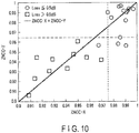
- FIG. 10 is a figure showing the relationships between ZNCC-Xs and ZNCC-Ys.
- the horizontal axis indicates ZNCC-Xs
- the vertical axis indicates ZNCC-Ys.
- the plotted circles indicate that connection losses are equal to or less than 0.5 dB.
- the plotted squares indicate that connection losses are equal to or greater than 0.5 dB.
- the dotted line indicates the threshold of ZNCC-Xs at which connection losses get equal to or less than 0.5 dB (e.g., 0.975).
- the broken line indicates the threshold of ZNCC-Ys at which connection losses get equal to or less than 0.5 dB (e.g., 0.964).
- a low connection loss can be achieved.
- a threshold is set at 0.964, and by setting a rotation angle so that both a ZNCC-X and a ZNCC-Y obtain peak values within the scope of the ZNCC-X and the ZNCC-Y each of which is equal to or greater than the threshold, a connection loss can be reduced.
- An alignment apparatus configured as above obtains side images of an optical fiber.
- the alignment apparatus calculates average luminances from the side images.
- the alignment apparatus defines a rotation angle at which correlation coefficients between the average luminances of the optical fiber and those of another optical fiber peak as an aligned rotation angle. As a result, the alignment apparatus can efficiently align the optical fiber.
- the alignment apparatus according to the second embodiment differs from that in the first embodiment in that an optical fiber is aligned with respect to a connector.
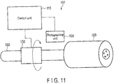
- FIG. 11 shows a configuration example of an alignment apparatus 101 according to the second embodiment.
- the alignment apparatus 101 aligns an optical fiber 102 with a connector 103 at a predetermined angle.
- the optical fiber 102 is configured in the same manner as the optical fiber 2.
- the connector 103 is an SC ferrule or an MT ferrule, for example.
- the alignment apparatus 101 comprises a control unit 110, a photographing unit 120, a gripper 130, etc.
- the control unit 110 controls the whole of the alignment apparatus 101.
- the control unit 110 aligns the optical fiber 102 on the basis of images photographed by the photographing unit 120.
- the control unit 110 is comprised by a CPU, a ROM, a RAM, an NVM, and an interface, for example.
- the control unit 110 may be a desktop PC, a notebook PC, or a tablet PC, for example.
- control unit 110 can be achieved by execution of a program by the CPU, for example. That is, the program is used for a computer that operates as at least a part of the alignment apparatus 101.
- the photographing unit 120 photographs side images of the optical fiber 102.
- the photographing unit 120 is configured in the same manner as the photographing unit 20.
- the gripper 130 retains the optical fiber 102, and rotates the optical fiber 102 in the axis direction of the optical fiber 102 on the basis of a signal from the control unit 110.
- the gripper 130 is configured in the same manner as the gripper 30.
- the control unit 110 previously stores reference side images.
- the reference side images are side images of the optical fiber 102 at an appropriate rotation angle (aligned rotation angle).
- the control unit 110 aligns the optical fiber 102 on the basis of the side images of the optical fiber 102 and the reference side images. That is, the control unit 110 rotates the optical fiber 102 so that correlation coefficients between the average luminances of the side images of the optical fiber 102 and those of the reference side images peak.
- the method for aligning the optical fiber 102 by the control unit 110 is the same as the method for aligning the optical fiber 2a by the control unit 10.
- the control unit 110 may previously store the average luminances of the reference side images.
- the alignment apparatus 101 is applied to alignment of a rotation angle of an optical fiber with respect to various members of a connector, such as fixation to the flange of an optical fiber adhesively fixed to a ferrule.
- An alignment apparatus configured as above can rotate an optical fiber at an angle at which correlation coefficients between the average luminances of reference side images and those of side images of the optical fiber peak. As a result, the alignment apparatus can rotate the optical fiber at an appropriate angle with respect to a connector. Accordingly, the alignment apparatus can align a rotation angle of the optical fiber with respect to the connector.
- the present invention is not restricted to the above embodiments as they are, but can be embodied in an implementation phase by a change of components within the scope of the gist.
- various inventions can be formed by proper combination of a plurality of components described in the above embodiments. For example, some components may be deleted from all the components shown in the embodiments. Furthermore, components crossing over different embodiments may be combined as necessary.
- the method described in each embodiment can be, as a program (software means) that can be executed by a calculator (computer), stored in a storage medium such as a magnetic disk (floppy (registered trademark) disk, hard disk, etc.), an optical disk (CD-ROM, DVD, MO, etc.), and a semiconductor memory (ROM, RAM, flash memory, etc.), and distributed through transmission by a communication medium.
- a program to be stored in a medium also encompasses a setting program that has a calculator configure a software means to be executed by the calculator (not only an execution program, but also a table or a data configuration).
- a calculator for achieving the present apparatus reads a program recorded in a storage medium, or, according to circumstances, constructs by a setting program a software means, which controls operation, thereby executing the above processing.
- a storage medium in this specification is not restricted to distribution use, and encompasses a storage medium such as a magnetic disk, and a semiconductor memory provided in a calculator, or in equipment connected through a network.
Landscapes
- Physics & Mathematics (AREA)
- General Physics & Mathematics (AREA)
- Optics & Photonics (AREA)
- Engineering & Computer Science (AREA)
- Plasma & Fusion (AREA)
- Mechanical Coupling Of Light Guides (AREA)
- Optical Couplings Of Light Guides (AREA)
Applications Claiming Priority (2)
| Application Number | Priority Date | Filing Date | Title |
|---|---|---|---|
| JP2016011873 | 2016-01-25 | ||
| PCT/JP2016/088997 WO2017130627A1 (fr) | 2016-01-25 | 2016-12-27 | Dispositif d'alignement et procédé d'alignement |
Publications (4)
| Publication Number | Publication Date |
|---|---|
| EP3379307A1 true EP3379307A1 (fr) | 2018-09-26 |
| EP3379307A4 EP3379307A4 (fr) | 2019-07-10 |
| EP3379307B1 EP3379307B1 (fr) | 2021-07-14 |
| EP3379307B9 EP3379307B9 (fr) | 2021-10-27 |
Family
ID=59397714
Family Applications (1)
| Application Number | Title | Priority Date | Filing Date |
|---|---|---|---|
| EP16888211.6A Active EP3379307B9 (fr) | 2016-01-25 | 2016-12-27 | Dispositif d'alignement et procédé d'alignement |
Country Status (5)
| Country | Link |
|---|---|
| US (1) | US10620372B2 (fr) |
| EP (1) | EP3379307B9 (fr) |
| JP (1) | JP6741693B2 (fr) |
| CN (1) | CN108496102B (fr) |
| WO (1) | WO2017130627A1 (fr) |
Families Citing this family (29)
| Publication number | Priority date | Publication date | Assignee | Title |
|---|---|---|---|---|
| WO2019131441A1 (fr) | 2017-12-27 | 2019-07-04 | 日本電信電話株式会社 | Dispositif de connexion, dispositif de fabrication de connecteur optique, procédé de connexion et procédé de fabrication de connecteur optique |
| JP6917324B2 (ja) * | 2018-03-09 | 2021-08-11 | Kddi株式会社 | マルチコア光ファイバの調心装置 |
| CN109061807B (zh) * | 2018-09-13 | 2020-07-03 | 苏州席正通信科技有限公司 | 一种用于光子芯片的光纤引出方法 |
| EP3757524B1 (fr) * | 2019-06-25 | 2024-06-05 | Universidad del Pais Vasco - Euskal Herriko Unibertsitatea (UPV/EHU) | Interféromètre composé à fibre optique multicoeur |
| US11740410B2 (en) * | 2019-09-23 | 2023-08-29 | Ofs Fitel, Llc | Routing of multicore optical fibers in data networks |
| US11906783B2 (en) | 2019-10-08 | 2024-02-20 | Nippon Telegraph And Telephone Corporation | Core position grasping method, connection method, and connection device |
| WO2021182085A1 (fr) * | 2020-03-11 | 2021-09-16 | 株式会社フジクラ | Procédé d'alignement de fibre multicœur, procédé de fabrication de connecteur de fibre multicœur, dispositif d'alignement de fibre multicœur et machine d'épissurage par fusion de fibre multicœur |
| CN111307073B (zh) * | 2020-03-16 | 2022-12-06 | 湖南米艾西测控技术有限公司 | 一种测量旋变定子与转子同轴度偏差的装置 |
| JP7347673B2 (ja) * | 2020-06-24 | 2023-09-20 | 日本電信電話株式会社 | 光ファイバ評価装置及び光ファイバ評価方法 |
| CN112255740B (zh) * | 2020-11-20 | 2022-03-18 | 长飞光纤光缆股份有限公司 | 一种多芯光纤连接器及其制造方法 |
| US11762148B2 (en) * | 2020-12-01 | 2023-09-19 | Afl Telecommunications Llc | Control systems and methods for aligning multicore fiber optic cables |
| WO2022125443A1 (fr) * | 2020-12-08 | 2022-06-16 | Ofs Fitel, Llc | Procédés et appareils d'alignement et d'épissage de fibres optiques |
| CA3203610A1 (fr) * | 2020-12-11 | 2022-06-16 | Nippon Telegraph And Telephone Corporation | Procede d'evaluation de fibre multic~ur et dispositif d'evaluation |
| CN116324546A (zh) * | 2020-12-22 | 2023-06-23 | 住友电气工业株式会社 | 光纤的方位推定方法和光纤部件的制造方法 |
| CN112764172B (zh) * | 2020-12-28 | 2022-03-29 | 武汉光迅科技股份有限公司 | 基于机器视觉的多通道预对准系统及多通道预对准方法 |
| US12298562B2 (en) * | 2021-04-29 | 2025-05-13 | Ram Photonics Industrial, Llc | Method and system for rotational alignment of polarization maintaining fibers |
| EP4379437A4 (fr) * | 2021-07-27 | 2024-11-06 | Sumitomo Electric Industries, Ltd. | Procédé d'alignement de fibre optique et dispositif d'alignement, et dispositif de connexion |
| EP4212489A1 (fr) * | 2022-01-18 | 2023-07-19 | Heraeus Quarzglas GmbH & Co. KG | Procédé et préforme pour la fabrication d'une fibre multicoeurs |
| CN118715463A (zh) * | 2022-02-17 | 2024-09-27 | 株式会社藤仓 | 光纤的调心方法、光纤连接体的制造方法、光纤的调心装置、以及光纤的熔接连接机 |
| WO2023170862A1 (fr) * | 2022-03-10 | 2023-09-14 | 日本電信電話株式会社 | Procédé de spécification de position d'âme, procédé de connexion de fibre optique et dispositif de connexion de fibre optique |
| EP4556875A4 (fr) * | 2022-07-11 | 2025-11-12 | Sumitomo Electric Industries | Procédé et dispositif de mesure des caractéristiques optiques d'une fibre optique à multicoeurs |
| CN119422089A (zh) * | 2022-08-08 | 2025-02-11 | 株式会社藤仓 | 多芯光纤、光器件以及多芯光纤的制造方法 |
| US20250383502A1 (en) * | 2022-08-08 | 2025-12-18 | Fujikura Ltd. | Multicore fiber, optical device, and multicore fiber assembly |
| CN115980920A (zh) * | 2022-12-21 | 2023-04-18 | 中天科技精密材料有限公司 | 光纤、光纤对准方法、装置、光纤熔接机和存储介质 |
| US20240264363A1 (en) * | 2023-02-06 | 2024-08-08 | Panduit Corp. | Ultra-Wideband Low Latency Multicore to Multicore Free-Space Optical Communications Using Parabolic Mirrors |
| JP7527436B1 (ja) | 2023-04-26 | 2024-08-02 | 株式会社フジクラ | 調心方法、調心システム、及び、ファイバ接続体の製造方法 |
| JPWO2024236731A1 (fr) * | 2023-05-16 | 2024-11-21 | ||
| US20260043710A1 (en) * | 2024-08-09 | 2026-02-12 | Corning Incorporated | Core element identification for heterogeneous multicore optical fibers |
| CN120255080A (zh) * | 2025-04-10 | 2025-07-04 | 广东工业大学 | 一种光纤接续方法及系统 |
Family Cites Families (18)
| Publication number | Priority date | Publication date | Assignee | Title |
|---|---|---|---|---|
| JP2782085B2 (ja) | 1989-05-26 | 1998-07-30 | 株式会社フジクラ | デュアルコア光フアイバの軸合せ方法 |
| JPH0815563A (ja) | 1994-07-01 | 1996-01-19 | Hitachi Cable Ltd | 非軸対称屈折率分布を有する光ファイバと光導波路との結合部におけるアライメント方法、光ファイバ固定構造及び結合部 |
| JP3168844B2 (ja) | 1994-10-13 | 2001-05-21 | 住友電気工業株式会社 | 定偏波光ファイバの融着接続方法 |
| SE506956C2 (sv) * | 1995-10-24 | 1998-03-09 | Ericsson Telefon Ab L M | Förfarande och anordning för att bestämma vinkelläget för en optisk axiell asymmetri, samt användning av förfarandet respektive anordningen |
| EP0813081A1 (fr) | 1996-06-12 | 1997-12-17 | Siemens Aktiengesellschaft | Procédé pour déterminer l'angle d'inclination d'au moins une fibre optique et dispositif pour la mise en oeuvre du procédé |
| JP3759241B2 (ja) * | 1996-06-12 | 2006-03-22 | 正廣 大出 | 木造住宅及び木質系住宅用土台の固定構造 |
| JP3744812B2 (ja) * | 2001-04-26 | 2006-02-15 | 住友電気工業株式会社 | 定偏波光ファイバの融着接続方法 |
| AU2002323522A1 (en) * | 2001-08-29 | 2003-03-18 | 3M Innovative Properties Company | Optical devices using shaped optical fibers and methods for making optical devices with shaped optical fibers |
| JP4190997B2 (ja) | 2003-09-24 | 2008-12-03 | 古河電気工業株式会社 | 光ファイバの融着接続装置と融着接続方法 |
| JP2005173210A (ja) | 2003-12-11 | 2005-06-30 | Furukawa Electric Co Ltd:The | 偏波面保持光ファイバの回転基準位置決定方法及び光ファイバ融着接続機 |
| DE602005013441D1 (de) * | 2004-04-09 | 2009-05-07 | Tomoegawa Paper Co Ltd | Verfahren zur Verbindung von optischen Fasern und optischen Komponenten unter Verwendung von Faserbiegungen |
| CA2739057A1 (fr) * | 2008-10-01 | 2010-04-08 | Afl Telecommunications Llc | Procede d'alignement de fibre optique a maintien de la polarisation par analyse de profil d'image |
| CN101419311B (zh) | 2008-11-11 | 2010-12-22 | 北京大学 | 一种保偏光纤侧视图像匹配对轴方法及其装置 |
| JP6082523B2 (ja) * | 2011-08-01 | 2017-02-15 | 古河電気工業株式会社 | マルチコアファイバの接続方法、マルチコアファイバ、マルチコアファイバの製造方法 |
| JP5303618B2 (ja) * | 2011-09-02 | 2013-10-02 | 株式会社フジクラ | 融着接続機及び光ファイバ判別方法 |
| JP5978979B2 (ja) | 2012-12-20 | 2016-08-24 | 富士通株式会社 | 光ファイバの姿勢を検出する方法および装置 |
| JP6287179B2 (ja) | 2013-12-25 | 2018-03-07 | 住友電気工業株式会社 | マルチコア光ファイバ及びマルチコア光ファイバコネクタの製造方法 |
| JP6598466B2 (ja) * | 2015-01-30 | 2019-10-30 | キヤノン株式会社 | 断層撮像装置、断層撮像方法、およびプログラム |
-
2016
- 2016-12-27 WO PCT/JP2016/088997 patent/WO2017130627A1/fr not_active Ceased
- 2016-12-27 US US16/062,034 patent/US10620372B2/en active Active
- 2016-12-27 EP EP16888211.6A patent/EP3379307B9/fr active Active
- 2016-12-27 JP JP2017563747A patent/JP6741693B2/ja active Active
- 2016-12-27 CN CN201680079835.8A patent/CN108496102B/zh active Active
Also Published As
| Publication number | Publication date |
|---|---|
| CN108496102A (zh) | 2018-09-04 |
| EP3379307B9 (fr) | 2021-10-27 |
| US20180372954A1 (en) | 2018-12-27 |
| CN108496102B (zh) | 2020-07-31 |
| JP6741693B2 (ja) | 2020-08-19 |
| EP3379307A4 (fr) | 2019-07-10 |
| JPWO2017130627A1 (ja) | 2018-09-20 |
| EP3379307B1 (fr) | 2021-07-14 |
| WO2017130627A1 (fr) | 2017-08-03 |
| US10620372B2 (en) | 2020-04-14 |
Similar Documents
| Publication | Publication Date | Title |
|---|---|---|
| EP3379307B9 (fr) | Dispositif d'alignement et procédé d'alignement | |
| US10025032B2 (en) | Alignment device, splicing device, aligning method, and splicing method for optical fibers | |
| US7548674B1 (en) | Alignment method for circular multi-core optical fiber | |
| US10338317B2 (en) | Systems and methods for traceable cables | |
| CN103119489A (zh) | 用于光学部件的成像接口 | |
| US11762148B2 (en) | Control systems and methods for aligning multicore fiber optic cables | |
| US20180350061A1 (en) | Apparatus and Method for Terminating and Testing Connectors | |
| KR20190034275A (ko) | 광 파이버 스플라이스를 평가하기 위한 방법 및 디바이스 | |
| US9134119B2 (en) | Optical fiber orientation detection method and apparatus | |
| US10612998B2 (en) | Method and apparatus for performing interrelation profile analysis | |
| JP7205643B2 (ja) | コア位置把握方法、接続方法、及び接続装置 | |
| US20250383502A1 (en) | Multicore fiber, optical device, and multicore fiber assembly | |
| DE60221258T2 (de) | Ausrichtungssystem für faseroptisches kabel | |
| WO2022138244A1 (fr) | Procédé pour estimation d'orientation de fibre optique et procédé pour fabrication de composant de fibre optique | |
| JP5985297B2 (ja) | 光ファイバ接続方法 | |
| US12613379B2 (en) | Splice-on optical connectors for multicore fibers | |
| Zheng | Auto-aligning and splicing PM-fibers of different types with a passive method | |
| JPH0815563A (ja) | 非軸対称屈折率分布を有する光ファイバと光導波路との結合部におけるアライメント方法、光ファイバ固定構造及び結合部 | |
| Kremp et al. | Polarity and twist rate detection for accurate and reliable low loss multicore fiber fusion splicing | |
| US11934018B2 (en) | Apparatus, method and storage medium for concentric alignment of cylindrical components | |
| JP4570227B2 (ja) | パンダファイバにおける応力付与部の位置検出調整方法 | |
| JP2022125758A (ja) | 融着接続機及び光ファイバの回転調心方法 | |
| CN206671610U (zh) | 一种高消光比保偏光纤阵列的制备装置 | |
| CN207019871U (zh) | 一种光纤连接损耗测量装置 | |
| US20120102059A1 (en) | Optical fiber optimization system |
Legal Events
| Date | Code | Title | Description |
|---|---|---|---|
| STAA | Information on the status of an ep patent application or granted ep patent |
Free format text: STATUS: THE INTERNATIONAL PUBLICATION HAS BEEN MADE |
|
| PUAI | Public reference made under article 153(3) epc to a published international application that has entered the european phase |
Free format text: ORIGINAL CODE: 0009012 |
|
| STAA | Information on the status of an ep patent application or granted ep patent |
Free format text: STATUS: REQUEST FOR EXAMINATION WAS MADE |
|
| 17P | Request for examination filed |
Effective date: 20180613 |
|
| AK | Designated contracting states |
Kind code of ref document: A1 Designated state(s): AL AT BE BG CH CY CZ DE DK EE ES FI FR GB GR HR HU IE IS IT LI LT LU LV MC MK MT NL NO PL PT RO RS SE SI SK SM TR |
|
| AX | Request for extension of the european patent |
Extension state: BA ME |
|
| DAV | Request for validation of the european patent (deleted) | ||
| DAX | Request for extension of the european patent (deleted) | ||
| A4 | Supplementary search report drawn up and despatched |
Effective date: 20190612 |
|
| RIC1 | Information provided on ipc code assigned before grant |
Ipc: G02B 6/38 20060101ALI20190605BHEP Ipc: G02B 6/26 20060101AFI20190605BHEP Ipc: G02B 6/02 20060101ALI20190605BHEP |
|
| STAA | Information on the status of an ep patent application or granted ep patent |
Free format text: STATUS: EXAMINATION IS IN PROGRESS |
|
| 17Q | First examination report despatched |
Effective date: 20200122 |
|
| GRAP | Despatch of communication of intention to grant a patent |
Free format text: ORIGINAL CODE: EPIDOSNIGR1 |
|
| STAA | Information on the status of an ep patent application or granted ep patent |
Free format text: STATUS: GRANT OF PATENT IS INTENDED |
|
| INTG | Intention to grant announced |
Effective date: 20200903 |
|
| GRAJ | Information related to disapproval of communication of intention to grant by the applicant or resumption of examination proceedings by the epo deleted |
Free format text: ORIGINAL CODE: EPIDOSDIGR1 |
|
| STAA | Information on the status of an ep patent application or granted ep patent |
Free format text: STATUS: EXAMINATION IS IN PROGRESS |
|
| INTC | Intention to grant announced (deleted) | ||
| GRAP | Despatch of communication of intention to grant a patent |
Free format text: ORIGINAL CODE: EPIDOSNIGR1 |
|
| STAA | Information on the status of an ep patent application or granted ep patent |
Free format text: STATUS: GRANT OF PATENT IS INTENDED |
|
| INTG | Intention to grant announced |
Effective date: 20210204 |
|
| GRAS | Grant fee paid |
Free format text: ORIGINAL CODE: EPIDOSNIGR3 |
|
| GRAA | (expected) grant |
Free format text: ORIGINAL CODE: 0009210 |
|
| STAA | Information on the status of an ep patent application or granted ep patent |
Free format text: STATUS: THE PATENT HAS BEEN GRANTED |
|
| AK | Designated contracting states |
Kind code of ref document: B1 Designated state(s): AL AT BE BG CH CY CZ DE DK EE ES FI FR GB GR HR HU IE IS IT LI LT LU LV MC MK MT NL NO PL PT RO RS SE SI SK SM TR |
|
| REG | Reference to a national code |
Ref country code: GB Ref legal event code: FG4D |
|
| REG | Reference to a national code |
Ref country code: IE Ref legal event code: FG4D |
|
| REG | Reference to a national code |
Ref country code: DE Ref legal event code: R096 Ref document number: 602016060771 Country of ref document: DE |
|
| REG | Reference to a national code |
Ref country code: AT Ref legal event code: REF Ref document number: 1411110 Country of ref document: AT Kind code of ref document: T Effective date: 20210815 |
|
| REG | Reference to a national code |
Ref country code: CH Ref legal event code: PK Free format text: BERICHTIGUNG B9 |
|
| REG | Reference to a national code |
Ref country code: LT Ref legal event code: MG9D |
|
| REG | Reference to a national code |
Ref country code: NL Ref legal event code: MP Effective date: 20210714 |
|
| REG | Reference to a national code |
Ref country code: AT Ref legal event code: MK05 Ref document number: 1411110 Country of ref document: AT Kind code of ref document: T Effective date: 20210714 |
|
| PG25 | Lapsed in a contracting state [announced via postgrant information from national office to epo] |
Ref country code: NO Free format text: LAPSE BECAUSE OF FAILURE TO SUBMIT A TRANSLATION OF THE DESCRIPTION OR TO PAY THE FEE WITHIN THE PRESCRIBED TIME-LIMIT Effective date: 20211014 Ref country code: NL Free format text: LAPSE BECAUSE OF FAILURE TO SUBMIT A TRANSLATION OF THE DESCRIPTION OR TO PAY THE FEE WITHIN THE PRESCRIBED TIME-LIMIT Effective date: 20210714 Ref country code: PT Free format text: LAPSE BECAUSE OF FAILURE TO SUBMIT A TRANSLATION OF THE DESCRIPTION OR TO PAY THE FEE WITHIN THE PRESCRIBED TIME-LIMIT Effective date: 20211115 Ref country code: FI Free format text: LAPSE BECAUSE OF FAILURE TO SUBMIT A TRANSLATION OF THE DESCRIPTION OR TO PAY THE FEE WITHIN THE PRESCRIBED TIME-LIMIT Effective date: 20210714 Ref country code: ES Free format text: LAPSE BECAUSE OF FAILURE TO SUBMIT A TRANSLATION OF THE DESCRIPTION OR TO PAY THE FEE WITHIN THE PRESCRIBED TIME-LIMIT Effective date: 20210714 Ref country code: HR Free format text: LAPSE BECAUSE OF FAILURE TO SUBMIT A TRANSLATION OF THE DESCRIPTION OR TO PAY THE FEE WITHIN THE PRESCRIBED TIME-LIMIT Effective date: 20210714 Ref country code: BG Free format text: LAPSE BECAUSE OF FAILURE TO SUBMIT A TRANSLATION OF THE DESCRIPTION OR TO PAY THE FEE WITHIN THE PRESCRIBED TIME-LIMIT Effective date: 20211014 Ref country code: AT Free format text: LAPSE BECAUSE OF FAILURE TO SUBMIT A TRANSLATION OF THE DESCRIPTION OR TO PAY THE FEE WITHIN THE PRESCRIBED TIME-LIMIT Effective date: 20210714 Ref country code: LT Free format text: LAPSE BECAUSE OF FAILURE TO SUBMIT A TRANSLATION OF THE DESCRIPTION OR TO PAY THE FEE WITHIN THE PRESCRIBED TIME-LIMIT Effective date: 20210714 Ref country code: RS Free format text: LAPSE BECAUSE OF FAILURE TO SUBMIT A TRANSLATION OF THE DESCRIPTION OR TO PAY THE FEE WITHIN THE PRESCRIBED TIME-LIMIT Effective date: 20210714 Ref country code: SE Free format text: LAPSE BECAUSE OF FAILURE TO SUBMIT A TRANSLATION OF THE DESCRIPTION OR TO PAY THE FEE WITHIN THE PRESCRIBED TIME-LIMIT Effective date: 20210714 |
|
| PG25 | Lapsed in a contracting state [announced via postgrant information from national office to epo] |
Ref country code: PL Free format text: LAPSE BECAUSE OF FAILURE TO SUBMIT A TRANSLATION OF THE DESCRIPTION OR TO PAY THE FEE WITHIN THE PRESCRIBED TIME-LIMIT Effective date: 20210714 Ref country code: LV Free format text: LAPSE BECAUSE OF FAILURE TO SUBMIT A TRANSLATION OF THE DESCRIPTION OR TO PAY THE FEE WITHIN THE PRESCRIBED TIME-LIMIT Effective date: 20210714 Ref country code: GR Free format text: LAPSE BECAUSE OF FAILURE TO SUBMIT A TRANSLATION OF THE DESCRIPTION OR TO PAY THE FEE WITHIN THE PRESCRIBED TIME-LIMIT Effective date: 20211015 |
|
| REG | Reference to a national code |
Ref country code: DE Ref legal event code: R097 Ref document number: 602016060771 Country of ref document: DE |
|
| PG25 | Lapsed in a contracting state [announced via postgrant information from national office to epo] |
Ref country code: DK Free format text: LAPSE BECAUSE OF FAILURE TO SUBMIT A TRANSLATION OF THE DESCRIPTION OR TO PAY THE FEE WITHIN THE PRESCRIBED TIME-LIMIT Effective date: 20210714 |
|
| PLBE | No opposition filed within time limit |
Free format text: ORIGINAL CODE: 0009261 |
|
| STAA | Information on the status of an ep patent application or granted ep patent |
Free format text: STATUS: NO OPPOSITION FILED WITHIN TIME LIMIT |
|
| PG25 | Lapsed in a contracting state [announced via postgrant information from national office to epo] |
Ref country code: SM Free format text: LAPSE BECAUSE OF FAILURE TO SUBMIT A TRANSLATION OF THE DESCRIPTION OR TO PAY THE FEE WITHIN THE PRESCRIBED TIME-LIMIT Effective date: 20210714 Ref country code: SK Free format text: LAPSE BECAUSE OF FAILURE TO SUBMIT A TRANSLATION OF THE DESCRIPTION OR TO PAY THE FEE WITHIN THE PRESCRIBED TIME-LIMIT Effective date: 20210714 Ref country code: RO Free format text: LAPSE BECAUSE OF FAILURE TO SUBMIT A TRANSLATION OF THE DESCRIPTION OR TO PAY THE FEE WITHIN THE PRESCRIBED TIME-LIMIT Effective date: 20210714 Ref country code: EE Free format text: LAPSE BECAUSE OF FAILURE TO SUBMIT A TRANSLATION OF THE DESCRIPTION OR TO PAY THE FEE WITHIN THE PRESCRIBED TIME-LIMIT Effective date: 20210714 Ref country code: CZ Free format text: LAPSE BECAUSE OF FAILURE TO SUBMIT A TRANSLATION OF THE DESCRIPTION OR TO PAY THE FEE WITHIN THE PRESCRIBED TIME-LIMIT Effective date: 20210714 Ref country code: AL Free format text: LAPSE BECAUSE OF FAILURE TO SUBMIT A TRANSLATION OF THE DESCRIPTION OR TO PAY THE FEE WITHIN THE PRESCRIBED TIME-LIMIT Effective date: 20210714 |
|
| 26N | No opposition filed |
Effective date: 20220419 |
|
| REG | Reference to a national code |
Ref country code: DE Ref legal event code: R119 Ref document number: 602016060771 Country of ref document: DE |
|
| PG25 | Lapsed in a contracting state [announced via postgrant information from national office to epo] |
Ref country code: MC Free format text: LAPSE BECAUSE OF FAILURE TO SUBMIT A TRANSLATION OF THE DESCRIPTION OR TO PAY THE FEE WITHIN THE PRESCRIBED TIME-LIMIT Effective date: 20210714 Ref country code: IT Free format text: LAPSE BECAUSE OF FAILURE TO SUBMIT A TRANSLATION OF THE DESCRIPTION OR TO PAY THE FEE WITHIN THE PRESCRIBED TIME-LIMIT Effective date: 20210714 |
|
| REG | Reference to a national code |
Ref country code: CH Ref legal event code: PL |
|
| GBPC | Gb: european patent ceased through non-payment of renewal fee |
Effective date: 20211227 |
|
| REG | Reference to a national code |
Ref country code: BE Ref legal event code: MM Effective date: 20211231 |
|
| PG25 | Lapsed in a contracting state [announced via postgrant information from national office to epo] |
Ref country code: LU Free format text: LAPSE BECAUSE OF NON-PAYMENT OF DUE FEES Effective date: 20211227 Ref country code: IE Free format text: LAPSE BECAUSE OF NON-PAYMENT OF DUE FEES Effective date: 20211227 Ref country code: GB Free format text: LAPSE BECAUSE OF NON-PAYMENT OF DUE FEES Effective date: 20211227 Ref country code: DE Free format text: LAPSE BECAUSE OF NON-PAYMENT OF DUE FEES Effective date: 20220701 |
|
| PG25 | Lapsed in a contracting state [announced via postgrant information from national office to epo] |
Ref country code: BE Free format text: LAPSE BECAUSE OF NON-PAYMENT OF DUE FEES Effective date: 20211231 |
|
| PG25 | Lapsed in a contracting state [announced via postgrant information from national office to epo] |
Ref country code: LI Free format text: LAPSE BECAUSE OF NON-PAYMENT OF DUE FEES Effective date: 20211231 Ref country code: CH Free format text: LAPSE BECAUSE OF NON-PAYMENT OF DUE FEES Effective date: 20211231 |
|
| PG25 | Lapsed in a contracting state [announced via postgrant information from national office to epo] |
Ref country code: HU Free format text: LAPSE BECAUSE OF FAILURE TO SUBMIT A TRANSLATION OF THE DESCRIPTION OR TO PAY THE FEE WITHIN THE PRESCRIBED TIME-LIMIT; INVALID AB INITIO Effective date: 20161227 |
|
| PG25 | Lapsed in a contracting state [announced via postgrant information from national office to epo] |
Ref country code: CY Free format text: LAPSE BECAUSE OF FAILURE TO SUBMIT A TRANSLATION OF THE DESCRIPTION OR TO PAY THE FEE WITHIN THE PRESCRIBED TIME-LIMIT Effective date: 20210714 |
|
| PG25 | Lapsed in a contracting state [announced via postgrant information from national office to epo] |
Ref country code: MK Free format text: LAPSE BECAUSE OF FAILURE TO SUBMIT A TRANSLATION OF THE DESCRIPTION OR TO PAY THE FEE WITHIN THE PRESCRIBED TIME-LIMIT Effective date: 20210714 |
|
| PG25 | Lapsed in a contracting state [announced via postgrant information from national office to epo] |
Ref country code: TR Free format text: LAPSE BECAUSE OF FAILURE TO SUBMIT A TRANSLATION OF THE DESCRIPTION OR TO PAY THE FEE WITHIN THE PRESCRIBED TIME-LIMIT Effective date: 20210714 |
|
| PG25 | Lapsed in a contracting state [announced via postgrant information from national office to epo] |
Ref country code: MT Free format text: LAPSE BECAUSE OF FAILURE TO SUBMIT A TRANSLATION OF THE DESCRIPTION OR TO PAY THE FEE WITHIN THE PRESCRIBED TIME-LIMIT Effective date: 20210714 |
|
| PGFP | Annual fee paid to national office [announced via postgrant information from national office to epo] |
Ref country code: FR Payment date: 20251229 Year of fee payment: 10 |