EP3379330B1 - Système d'imagerie pour véhicule à moteur - Google Patents
Système d'imagerie pour véhicule à moteur Download PDFInfo
- Publication number
- EP3379330B1 EP3379330B1 EP17161816.8A EP17161816A EP3379330B1 EP 3379330 B1 EP3379330 B1 EP 3379330B1 EP 17161816 A EP17161816 A EP 17161816A EP 3379330 B1 EP3379330 B1 EP 3379330B1
- Authority
- EP
- European Patent Office
- Prior art keywords
- retainer ring
- camera module
- imaging system
- ring
- housing part
- Prior art date
- Legal status (The legal status is an assumption and is not a legal conclusion. Google has not performed a legal analysis and makes no representation as to the accuracy of the status listed.)
- Active
Links
Images

Classifications
-
- G—PHYSICS
- G03—PHOTOGRAPHY; CINEMATOGRAPHY; ANALOGOUS TECHNIQUES USING WAVES OTHER THAN OPTICAL WAVES; ELECTROGRAPHY; HOLOGRAPHY
- G03B—APPARATUS OR ARRANGEMENTS FOR TAKING PHOTOGRAPHS OR FOR PROJECTING OR VIEWING THEM; APPARATUS OR ARRANGEMENTS EMPLOYING ANALOGOUS TECHNIQUES USING WAVES OTHER THAN OPTICAL WAVES; ACCESSORIES THEREFOR
- G03B17/00—Details of cameras or camera bodies; Accessories therefor
- G03B17/02—Bodies
Definitions
- the invention relates to an imaging system for a motor vehicle comprising the features of the preamble of claim 1.
- An imaging system for a motor vehicle comprising the features of the preamble of claim 1 is known for example from the EP 2 942 939 A1 .
- the imaging system comprises a camera housing part and at least one camera module to be mounted to said camera housing part, wherein the camera module comprises a lens objective, a lens holder holding said lens objective, an image sensor and a back plate holding said image sensor.
- a camera module in which a lens is attached to the camera module by being clamped by a lens cover and a positioning ring, wherein the lens cover is fixed by partially engaging protrusions of the lens holder, is known from the US 2012/0037820 A1 .
- the camera module is attached by rotation locking means.
- the rotation locking means cooperate with each other in order to realize predefined orientation and alignment of the camera module and may comprise bores and corresponding pins. Therefore, it is prevented that the camera module may change its position or orientation with respect to a roll angle after the attachment at the camera housing part and after the attachment of the imaging system at a vehicle.
- the attachment of the camera module in the camera housing part is realized by several assembly steps. First of all, the camera module needs to be arranged in a predefined position considering the final alignment and orientation. In the next step, the camera module is fixed to the housing part via said pins engaging said bores in a predefined roll angle. Nevertheless, the position may vary from the predefined position by e.g. different mounting forces or tolerances of the bores and pins. This may eventually lead to tilting of the camera module.
- the camera module is provided with one or more radially outwardly directed protrusions and a closed retainer ring, wherein the retainer ring is elastically deformable, and the retainer ring comprises a first ring element made from a rigid material and a second ring element made from a flexible material, and the retainer ring is attached by pushing it over the at least one protrusions under elastic deformation of the retainer ring to an attachment position, wherein the camera module is attached to the camera housing part by being clamped to the housing part when the retainer ring is in the attached position.
- the suggested imaging system comprises several advantages.
- Assembling the imaging system is realized by inserting of the camera module into an opening of the camera housing and pushing the retainer ring over the camera module to the attachment position.
- the retainer ring In the attachment position the retainer ring is arranged between the outwardly directed protrusions of the camera module and a surface of the camera housing part.
- the retainer ring engages the protrusions and is therefore fixed against movement towards and slipping over the protrusions.
- the solution enables an attachment in a single opening without additional bores or the like with equal distributed clamping forces between the retainer ring and the camera housing part.
- rigid material is to be understood as a material that allows for assembling of the retainer ring and the camera module. Therefore, the rigid material is elastically deformable in a way that allows the retainer ring to be bent outwardly, when being pushed over the protrusions, without cracking.
- Providing the retainer ring with a second ring element made from a flexible material enables for equally distributed load at the camera housing part and proper sealing of the opening of the camera housing part.
- flexible material is to be understood as highly flexible and elastically deformable with much less effort compared to the rigid material of the first ring element.
- the flexible material may therefore be a rubber-like material.
- the maximum load of the camera module and the camera housing in the areas of the attachment may be reduced, which results in a reduced influence of the attachment forces to the final orientation of the camera module in the attachment position.
- the first ring element of the retainer ring may be partially slit around its perimeter along a length axis of the camera module.
- the length axis of the camera module represents the direction along which the retainer ring is moved to slip over the protrusions until it clips behind the protrusions to the attachment position.
- the retainer ring being partially slit along this axis, leads to several tab- or tooth-like elements extending between the slits.
- the tooth-elements When moving the retainer ring along the camera module towards the attachment position, the tooth-elements may be elastically deformed easier, i.e. with less force needed to push the rigid part of the retainer ring over the protrusions.
- the tooth-like elements are bent outwardly, while slipping over the protrusions with much less force effort.
- the slits in the perimeter of the first ring element may be arranged equidistant in a circumferential direction.
- the pushing forces are equally distributed in a circumferential direction preventing tilting of the retainer ring while being pushed to its attachment position.
- the distance between two adjacently arranged slits may be smaller than the width of the at least one protrusions of the camera module in circumferential direction. This results in that at least two of the tooth-like elements of the retainer ring are in touch condition with each protrusion of the camera module, further reducing the force efforts when pushing the retainer ring into its attachment position. Furthermore, it is preferred that the slits may be filled with said flexible material of said second ring element of the retainer ring, which supports the elastic deformation and allows for a closed surface of the retainer ring supporting the sealing of the opening of the camera housing.
- the first ring element of the retainer ring comprises a first tubular part and a collar extending radially inwardly from the tubular part.
- the retainer ring may act thereby additionally as a protection for the camera module by surrounding the camera module partially and especially the lens objective at the front side with the tubular part.
- the retainer ring is only engaging with the collar between the protrusions and the surface of the camera housing part, which fixes the camera module in the camera housing part, wherein the tubular part is not loaded.
- the assembly is facilitated because the retainer ring may be handled easier by grasping the retainer ring at the tubular part from the side opposing the collar and pushing it over the camera module and the protrusions with the collar.
- the collar is arranged at the end of the first tubular part, which is faced towards the surface of the camera housing part in the mounted position, so that the retainer ring is pushed in a first step with the collar over the protrusions when mounting the camera module at the camera housing via the retainer ring and moved over the protrusions until the final attachment position is reached.
- the slits extend from the first tubular part to the collar.
- the collar extending between two adjacent slits is part of one of the tooth-like elements facilitating easier attachment of the camera module by pushing the collar part of the retainer ring over the protrusions with less force effort.
- the second ring element of the retainer ring with a second tubular part, adjacently arranged to the collar in direction of the length axis of the camera module.
- the second tubular part facing to the camera housing and made from a flexible material, e.g. rubber-like soft plastic, it performs as a gasket and supports sealing of the opening of the camera housing part.
- the camera module comprises a cylindrical shape
- the retainer ring comprises a circular ring shape.
- the retainer ring is therefore loaded by an equally distributed load when attached to the camera housing and the assembly is facilitated since the retainer ring may be attached independent from its circumferential orientation.
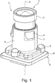
- a camera module 1 as a preassembled module comprising as basic components a lens objective 2, a lens holder 3 holding said lens objective 2 and a printed circuit board 6 fixed at the lens holder 3.
- the lens objective 2 may be screwed into the lens holder 3 and may comprise itself a stack of several single lenses.
- the printed circuit board 6 may comprise a not shown image sensor which is positioned in a predefined position in relation to the lens objective 2 at the back end 5 of the camera module 1, so that the light entering through the lenses of the lens objective 2 from the front end 7 of the camera module 1 hits onto the image sensor from a predefined direction.
- the lens holder 3 can be seen as a central part of the camera module 1 as it serves to fix the lens objective 2 and also the printed circuit board 6, so both parts are aligned in relation to each other because of the fixation at a common part.
- the lens holder 3 is designed with a cylindrical tube body 8.
- the lens holder 3 is provided with protrusions 4, which are designed with a conical surface having an increasing thickness in the direction towards the back end 5 of the camera module 1.
- centering surfaces 9 may be provided at the back end part 5 of the camera module 1.
- Three different types of lens holders 3 are shown in Fig. 2A to 2C . In Fig.
- the lens holder 3 is designed as a cylindrical tube body 8 provided with a single protrusion 4 extending circularly in a circumferential direction of the tube body 8. Therefore, the protrusion 4 has an increasing thickness in the direction of the back end 5 of the camera module 1.
- Other embodiments of the tube body 8 are shown in Fig. 2B and 2C with four, respectively six protrusions 4 arranged in a circumferential direction of the tube body 8.
- Other designs of the protrusions 4 may also be possible, if they allow for pushing the retainer ring 10 over the protrusions 4 as well as for snapping with the collar 11 of the retainer ring 10 behind the backside of the protrusions 4.
- the retainer ring 10 is shown in Figs. 3A and 3B presenting an embodiment comprising a first ring element 12 made from a rigid material and a second ring element 13 made from a flexible material and a collar 11 with slits 14 extending from the first ring element 12 to the collar 11.
- Those parts of the first ring element 12 and the collar 11 which are arranged between two slits 14 represent a tooth-like element 15.
- the second ring element 13 is made of a flexible material and the slits 14 are filled with the same material.
- a rubber-like soft plastic polymer, elastomer or rubber material
- the collar 11 parts of the tooth-like elements 15 are in contact with the protrusions 4 and bend outwardly following the increasing thickness of the protrusions 4. Therefore, the rigid material of the first ring element 12 have to be elastically deformable to an amount allowing the tooth-like elements 15 to bend outwardly when being pushed over the protrusions 4 without cracking.
- the slits 14 allow for a bending with less bending force needed compared to a retainer ring 10 without slits 14, while the flexible, elastomeric filling of the slits 14 maintains a closed surface and sealing of the retainer ring 10.
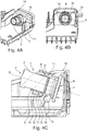
- FIGs. 4A to 4C it is shown the imaging system with a camera housing part 16 and the camera module 1 attached thereto.
- the camera module 1 is arranged in an opening 17 of the mounting surface 18 of the camera housing part 16 and fixed by a retainer ring 10 like described in the following.
- the camera module 1 is inserted with the lens objective 2 in a first step from the back side of the mounting surface 18 into the opening 17.
- the retainer ring 10 comprises a first tubular part 12 and a radially inwardly directed collar 11 like shown in Fig. 4C .
- the retainer ring 10 is designed either by choice of a special material and/or by designing a special geometry with for example weakened sections in an elastically deformable manner, so that the retainer ring 10 may, in a second step, be pushed with the collar 11 under elastic deformation over the protrusions 4 and snapping with the collar 11 behind the backside of the protrusions 4 to the attachment position.
- the thickness of the retainer ring 10 or of the collar 11 in the direction of the length axis A is designed so that the thickness of the collar 11 including the thickness of the elastomeric second ring element 13 is approximately identical or slightly greater than the distance between the surface 18 of the camera housing part 16 and the side of the protrusions 4 facing towards the surface 18 of the housing part 16 like shown in Fig. 4C . Therefore, the second ring element 13 is loaded by a pressure force and deformed when the camera module 1 is fixed in the mounting position by the retainer ring 10 to tighten and seal the opening 17 of the camera housing part 16.
- the protrusions 4 are designed with conical surface with in axial direction towards the camera housing part 16 increasing thickness, wherein the conical outer surfaces may also be shaped spherical in circumferential direction. Therefore, the retainer ring 10 is deformed continuously increasing when the retainer ring 10 is pushed over the protrusions 4, which facilitates the mounting process.
- centering surfaces 9 may be provided, so that the camera module 1 may dive with the centering surfaces 9 into recesses 19 provided at the camera housing part 16, to a predetermined position in axial as well as in circumferential direction like shown in Figure 4C .
- the centering surfaces 9 are pressed into the corresponding recesses 19 and the protrusions 4 are pressed with their end faces against the collar 11 of the retainer ring 10 and the retainer ring 10 finally against the surface 18 of the camera housing part 16, so that the camera module 1 is attached to the camera housing part 16 by clamping.
- the mounting process of the camera module 1 needs therefore only two steps, inserting of the camera module 1 into the opening 17 and pushing the retainer ring 10 over the lens holder 3 to the attachment position. Since the image sensor is arranged in a fixed position with respect to the lens holder 3 and the lens objective 2 is also fixed at the lens holder 3, the lens objective 2 got an orientation and position relating to the image sensor which is independent from the mounting of the camera module 1 at the camera housing part 16.
Landscapes
- Physics & Mathematics (AREA)
- General Physics & Mathematics (AREA)
- Lens Barrels (AREA)
- Studio Devices (AREA)
Claims (9)
- Un système d'imagerie pour un véhicule à moteur, comprenant- une partie de boîtier de caméra (16) et au moins un module de caméra (1) destiné à être monté sur ladite partie de boîtier de caméra (16), caractérisé en ce- que le module de caméra (1) est pourvu d'au moins une saillie (4) dirigée radialement vers l'extérieur, et- qu'une bague de retenue fermée (10) est prévue dans la partie de boîtier de caméra, dans lequel- la bague de retenue fermée (10) est déformable élastiquement, et- la bague de retenue fermée (10) comprend un premier élément de bague (12) réalisé à partir d'un matériau rigide et un second élément de bague (13) réalisé à partir d'un matériau flexible, et- la bague de retenue fermée (10) est fixée au module de caméra en la poussant sur l'au moins une saillie (4) sous la déformation élastique de la bague de retenue fermée (10) vers une position de fixation, dans lequel- dans la position de fixation, la bague de retenue fermée (10) est agencée entre l'au moins une saillie (4) dirigée vers l'extérieur du module de caméra (1) et une surface de la partie de boîtier de caméra (16), et- le module de caméra (1) est fixé à la partie de boîtier de caméra (16) en étant serré sur la partie de boîtier de caméra (16) lorsque la bague de retenue fermée (10) est dans la position de fixation.
- Un système d'imagerie selon la revendication 1, caractérisé en ce- que le premier élément de bague (12) de la bague de retenue fermée (10) est partiellement fendu (14) autour de son périmètre selon un axe de longueur (A) du module de caméra (1).
- Un système d'imagerie selon la revendication 2, caractérisé en ce- que les fentes (14) dans le périmètre du premier élément de bague (12) sont agencées équidistantes dans une direction circonférentielle.
- Un système d'imagerie selon la revendication 2 ou 3, caractérisé en ce- que la distance en direction circonférentielle entre deux fentes (14) agencées de façon adjacente est plus petite que la largeur de l'au moins une saillie (4) du module de caméra (1) en direction circonférentielle.
- Un système d'imagerie selon l'une des revendications 2 à 4, caractérisé en ce- que les fentes (14) sont remplies dudit matériau flexible dudit second élément de bague (13) de la bague de retenue (10).
- Un système d'imagerie selon l'une quelconque des revendications 2 à 5, caractérisé en ce- que le premier élément de bague (12) de la bague de retenue (10) comprend une première partie tubulaire et un collier (11) s'étendant radialement vers l'intérieur depuis la première partie tubulaire.
- Un système d'imagerie selon la revendication 6, caractérisé en ce- que les fentes (14) s'étendent de la première partie tubulaire (12) au collier (11).
- Un système d'imagerie selon la revendication 6 ou 7, caractérisé en ce- que le second élément de bague (13) de la bague de retenue (10) comprend une seconde partie tubulaire, agencée de façon adjacente au collier (11) en direction de l'axe de longueur (A) du module de caméra (1).
- Un système d'imagerie selon l'une quelconque des revendications précédentes, caractérisé en ce- que le module de caméra (1) comprend une forme cylindrique, et- que la bague de retenue fermée (10) comprend une forme de bague circulaire.
Priority Applications (1)
| Application Number | Priority Date | Filing Date | Title |
|---|---|---|---|
| EP17161816.8A EP3379330B1 (fr) | 2017-03-20 | 2017-03-20 | Système d'imagerie pour véhicule à moteur |
Applications Claiming Priority (1)
| Application Number | Priority Date | Filing Date | Title |
|---|---|---|---|
| EP17161816.8A EP3379330B1 (fr) | 2017-03-20 | 2017-03-20 | Système d'imagerie pour véhicule à moteur |
Publications (2)
| Publication Number | Publication Date |
|---|---|
| EP3379330A1 EP3379330A1 (fr) | 2018-09-26 |
| EP3379330B1 true EP3379330B1 (fr) | 2020-10-21 |
Family
ID=58401397
Family Applications (1)
| Application Number | Title | Priority Date | Filing Date |
|---|---|---|---|
| EP17161816.8A Active EP3379330B1 (fr) | 2017-03-20 | 2017-03-20 | Système d'imagerie pour véhicule à moteur |
Country Status (1)
| Country | Link |
|---|---|
| EP (1) | EP3379330B1 (fr) |
Families Citing this family (1)
| Publication number | Priority date | Publication date | Assignee | Title |
|---|---|---|---|---|
| EP4093009B1 (fr) | 2021-05-18 | 2025-04-16 | Magna Electronics Sweden AB | Système d'imagerie pour véhicule à moteur |
Family Cites Families (6)
| Publication number | Priority date | Publication date | Assignee | Title |
|---|---|---|---|---|
| EP1005692B2 (fr) * | 1997-08-21 | 2006-12-27 | Valeo Schalter und Sensoren GmbH | Douille de fixation de capteurs soudee au pare-chocs d'un vehicule automobile |
| CN100422788C (zh) * | 2004-01-30 | 2008-10-01 | 皇家飞利浦电子股份有限公司 | 变焦透镜组件 |
| JP4402164B1 (ja) * | 2009-04-06 | 2010-01-20 | 株式会社オプトエレクトロニクス | 液体レンズ光学体及び光学的情報読取装置 |
| DE102012223509A1 (de) * | 2012-12-18 | 2015-08-13 | Robert Bosch Gmbh | Imagermodul und Verfahren zum Herstellen eines Imagermoduls |
| DE102013212748A1 (de) * | 2013-06-28 | 2014-12-31 | Robert Bosch Gmbh | Imagermodul für eine Kamera, Kamera und Verfahren zum Herstellen des Imagermoduls |
| EP2942939A1 (fr) | 2014-05-07 | 2015-11-11 | Autoliv Development AB | Système d'imagerie pour véhicule automobile et procédé de montage d'un système d'imagerie |
-
2017
- 2017-03-20 EP EP17161816.8A patent/EP3379330B1/fr active Active
Non-Patent Citations (1)
| Title |
|---|
| None * |
Also Published As
| Publication number | Publication date |
|---|---|
| EP3379330A1 (fr) | 2018-09-26 |
Similar Documents
| Publication | Publication Date | Title |
|---|---|---|
| US9762783B2 (en) | Imager module and method for manufacturing an imager module | |
| US11466714B2 (en) | Fastening arrangement with damping effect and component connection to the fastening arrangement | |
| AU2011214879B2 (en) | Connection device for a plastic tube | |
| US10637188B2 (en) | Electrical plug connector | |
| JP6501460B2 (ja) | 特にステアリングコラムのための転がり軸受装置 | |
| EP3330131B1 (fr) | Dispositif de support pour une unité de capteur de véhicule | |
| US10855897B2 (en) | Imaging system for a motor vehicle | |
| EP3379330B1 (fr) | Système d'imagerie pour véhicule à moteur | |
| US20070001453A1 (en) | Protection cover for quick connector | |
| EP3475746A1 (fr) | Boîtier destiné à un connecteur sur un câble | |
| US6892602B2 (en) | Device for fastening a casing tube switch module to the casing tube of a motor vehicle steering shaft | |
| JP2002526728A (ja) | ベローズ形カバー部材 | |
| US7339757B2 (en) | Lens barrel | |
| EP3379331B1 (fr) | Système d'imagerie pour véhicule à moteur | |
| JP7633982B2 (ja) | グロメット | |
| US20020069474A1 (en) | Wiper device | |
| US10844882B2 (en) | Rod end cover | |
| JP3246941U (ja) | バッテリーターミナルのためのアダプタリング及びバッテリーターミナル | |
| US6768597B2 (en) | Mount for optical elements | |
| EP4057613B1 (fr) | Dispositif de caméra de véhicule | |
| JP6741508B2 (ja) | コントロールケーブル | |
| EP4389528A1 (fr) | Support de caméra et système de caméra pour un véhicule automobile | |
| JP7662691B2 (ja) | グロメット | |
| US11474322B2 (en) | Lens apparatus and imaging apparatus having the same | |
| EP4093009B1 (fr) | Système d'imagerie pour véhicule à moteur |
Legal Events
| Date | Code | Title | Description |
|---|---|---|---|
| PUAI | Public reference made under article 153(3) epc to a published international application that has entered the european phase |
Free format text: ORIGINAL CODE: 0009012 |
|
| STAA | Information on the status of an ep patent application or granted ep patent |
Free format text: STATUS: THE APPLICATION HAS BEEN PUBLISHED |
|
| AK | Designated contracting states |
Kind code of ref document: A1 Designated state(s): AL AT BE BG CH CY CZ DE DK EE ES FI FR GB GR HR HU IE IS IT LI LT LU LV MC MK MT NL NO PL PT RO RS SE SI SK SM TR |
|
| AX | Request for extension of the european patent |
Extension state: BA ME |
|
| STAA | Information on the status of an ep patent application or granted ep patent |
Free format text: STATUS: REQUEST FOR EXAMINATION WAS MADE |
|
| 17P | Request for examination filed |
Effective date: 20190325 |
|
| RBV | Designated contracting states (corrected) |
Designated state(s): AL AT BE BG CH CY CZ DE DK EE ES FI FR GB GR HR HU IE IS IT LI LT LU LV MC MK MT NL NO PL PT RO RS SE SI SK SM TR |
|
| RIC1 | Information provided on ipc code assigned before grant |
Ipc: G03B 17/02 20060101AFI20200219BHEP |
|
| GRAJ | Information related to disapproval of communication of intention to grant by the applicant or resumption of examination proceedings by the epo deleted |
Free format text: ORIGINAL CODE: EPIDOSDIGR1 |
|
| GRAP | Despatch of communication of intention to grant a patent |
Free format text: ORIGINAL CODE: EPIDOSNIGR1 |
|
| GRAP | Despatch of communication of intention to grant a patent |
Free format text: ORIGINAL CODE: EPIDOSNIGR1 |
|
| STAA | Information on the status of an ep patent application or granted ep patent |
Free format text: STATUS: GRANT OF PATENT IS INTENDED |
|
| INTG | Intention to grant announced |
Effective date: 20200508 |
|
| GRAS | Grant fee paid |
Free format text: ORIGINAL CODE: EPIDOSNIGR3 |
|
| GRAA | (expected) grant |
Free format text: ORIGINAL CODE: 0009210 |
|
| STAA | Information on the status of an ep patent application or granted ep patent |
Free format text: STATUS: THE PATENT HAS BEEN GRANTED |
|
| AK | Designated contracting states |
Kind code of ref document: B1 Designated state(s): AL AT BE BG CH CY CZ DE DK EE ES FI FR GB GR HR HU IE IS IT LI LT LU LV MC MK MT NL NO PL PT RO RS SE SI SK SM TR |
|
| REG | Reference to a national code |
Ref country code: GB Ref legal event code: FG4D |
|
| REG | Reference to a national code |
Ref country code: CH Ref legal event code: EP |
|
| REG | Reference to a national code |
Ref country code: DE Ref legal event code: R096 Ref document number: 602017025705 Country of ref document: DE |
|
| REG | Reference to a national code |
Ref country code: IE Ref legal event code: FG4D |
|
| REG | Reference to a national code |
Ref country code: AT Ref legal event code: REF Ref document number: 1326412 Country of ref document: AT Kind code of ref document: T Effective date: 20201115 |
|
| REG | Reference to a national code |
Ref country code: AT Ref legal event code: MK05 Ref document number: 1326412 Country of ref document: AT Kind code of ref document: T Effective date: 20201021 |
|
| REG | Reference to a national code |
Ref country code: NL Ref legal event code: MP Effective date: 20201021 |
|
| PG25 | Lapsed in a contracting state [announced via postgrant information from national office to epo] |
Ref country code: FI Free format text: LAPSE BECAUSE OF FAILURE TO SUBMIT A TRANSLATION OF THE DESCRIPTION OR TO PAY THE FEE WITHIN THE PRESCRIBED TIME-LIMIT Effective date: 20201021 Ref country code: GR Free format text: LAPSE BECAUSE OF FAILURE TO SUBMIT A TRANSLATION OF THE DESCRIPTION OR TO PAY THE FEE WITHIN THE PRESCRIBED TIME-LIMIT Effective date: 20210122 Ref country code: NO Free format text: LAPSE BECAUSE OF FAILURE TO SUBMIT A TRANSLATION OF THE DESCRIPTION OR TO PAY THE FEE WITHIN THE PRESCRIBED TIME-LIMIT Effective date: 20210121 Ref country code: RS Free format text: LAPSE BECAUSE OF FAILURE TO SUBMIT A TRANSLATION OF THE DESCRIPTION OR TO PAY THE FEE WITHIN THE PRESCRIBED TIME-LIMIT Effective date: 20201021 Ref country code: PT Free format text: LAPSE BECAUSE OF FAILURE TO SUBMIT A TRANSLATION OF THE DESCRIPTION OR TO PAY THE FEE WITHIN THE PRESCRIBED TIME-LIMIT Effective date: 20210222 |
|
| REG | Reference to a national code |
Ref country code: LT Ref legal event code: MG4D |
|
| PG25 | Lapsed in a contracting state [announced via postgrant information from national office to epo] |
Ref country code: SE Free format text: LAPSE BECAUSE OF FAILURE TO SUBMIT A TRANSLATION OF THE DESCRIPTION OR TO PAY THE FEE WITHIN THE PRESCRIBED TIME-LIMIT Effective date: 20201021 Ref country code: LV Free format text: LAPSE BECAUSE OF FAILURE TO SUBMIT A TRANSLATION OF THE DESCRIPTION OR TO PAY THE FEE WITHIN THE PRESCRIBED TIME-LIMIT Effective date: 20201021 Ref country code: PL Free format text: LAPSE BECAUSE OF FAILURE TO SUBMIT A TRANSLATION OF THE DESCRIPTION OR TO PAY THE FEE WITHIN THE PRESCRIBED TIME-LIMIT Effective date: 20201021 Ref country code: IS Free format text: LAPSE BECAUSE OF FAILURE TO SUBMIT A TRANSLATION OF THE DESCRIPTION OR TO PAY THE FEE WITHIN THE PRESCRIBED TIME-LIMIT Effective date: 20210221 Ref country code: BG Free format text: LAPSE BECAUSE OF FAILURE TO SUBMIT A TRANSLATION OF THE DESCRIPTION OR TO PAY THE FEE WITHIN THE PRESCRIBED TIME-LIMIT Effective date: 20210121 Ref country code: AT Free format text: LAPSE BECAUSE OF FAILURE TO SUBMIT A TRANSLATION OF THE DESCRIPTION OR TO PAY THE FEE WITHIN THE PRESCRIBED TIME-LIMIT Effective date: 20201021 Ref country code: ES Free format text: LAPSE BECAUSE OF FAILURE TO SUBMIT A TRANSLATION OF THE DESCRIPTION OR TO PAY THE FEE WITHIN THE PRESCRIBED TIME-LIMIT Effective date: 20201021 |
|
| PG25 | Lapsed in a contracting state [announced via postgrant information from national office to epo] |
Ref country code: NL Free format text: LAPSE BECAUSE OF FAILURE TO SUBMIT A TRANSLATION OF THE DESCRIPTION OR TO PAY THE FEE WITHIN THE PRESCRIBED TIME-LIMIT Effective date: 20201021 Ref country code: HR Free format text: LAPSE BECAUSE OF FAILURE TO SUBMIT A TRANSLATION OF THE DESCRIPTION OR TO PAY THE FEE WITHIN THE PRESCRIBED TIME-LIMIT Effective date: 20201021 |
|
| REG | Reference to a national code |
Ref country code: DE Ref legal event code: R097 Ref document number: 602017025705 Country of ref document: DE |
|
| PG25 | Lapsed in a contracting state [announced via postgrant information from national office to epo] |
Ref country code: LT Free format text: LAPSE BECAUSE OF FAILURE TO SUBMIT A TRANSLATION OF THE DESCRIPTION OR TO PAY THE FEE WITHIN THE PRESCRIBED TIME-LIMIT Effective date: 20201021 Ref country code: SM Free format text: LAPSE BECAUSE OF FAILURE TO SUBMIT A TRANSLATION OF THE DESCRIPTION OR TO PAY THE FEE WITHIN THE PRESCRIBED TIME-LIMIT Effective date: 20201021 Ref country code: CZ Free format text: LAPSE BECAUSE OF FAILURE TO SUBMIT A TRANSLATION OF THE DESCRIPTION OR TO PAY THE FEE WITHIN THE PRESCRIBED TIME-LIMIT Effective date: 20201021 Ref country code: EE Free format text: LAPSE BECAUSE OF FAILURE TO SUBMIT A TRANSLATION OF THE DESCRIPTION OR TO PAY THE FEE WITHIN THE PRESCRIBED TIME-LIMIT Effective date: 20201021 Ref country code: SK Free format text: LAPSE BECAUSE OF FAILURE TO SUBMIT A TRANSLATION OF THE DESCRIPTION OR TO PAY THE FEE WITHIN THE PRESCRIBED TIME-LIMIT Effective date: 20201021 Ref country code: RO Free format text: LAPSE BECAUSE OF FAILURE TO SUBMIT A TRANSLATION OF THE DESCRIPTION OR TO PAY THE FEE WITHIN THE PRESCRIBED TIME-LIMIT Effective date: 20201021 |
|
| PLBE | No opposition filed within time limit |
Free format text: ORIGINAL CODE: 0009261 |
|
| STAA | Information on the status of an ep patent application or granted ep patent |
Free format text: STATUS: NO OPPOSITION FILED WITHIN TIME LIMIT |
|
| PG25 | Lapsed in a contracting state [announced via postgrant information from national office to epo] |
Ref country code: DK Free format text: LAPSE BECAUSE OF FAILURE TO SUBMIT A TRANSLATION OF THE DESCRIPTION OR TO PAY THE FEE WITHIN THE PRESCRIBED TIME-LIMIT Effective date: 20201021 |
|
| 26N | No opposition filed |
Effective date: 20210722 |
|
| PG25 | Lapsed in a contracting state [announced via postgrant information from national office to epo] |
Ref country code: MC Free format text: LAPSE BECAUSE OF FAILURE TO SUBMIT A TRANSLATION OF THE DESCRIPTION OR TO PAY THE FEE WITHIN THE PRESCRIBED TIME-LIMIT Effective date: 20201021 Ref country code: IT Free format text: LAPSE BECAUSE OF FAILURE TO SUBMIT A TRANSLATION OF THE DESCRIPTION OR TO PAY THE FEE WITHIN THE PRESCRIBED TIME-LIMIT Effective date: 20201021 Ref country code: AL Free format text: LAPSE BECAUSE OF FAILURE TO SUBMIT A TRANSLATION OF THE DESCRIPTION OR TO PAY THE FEE WITHIN THE PRESCRIBED TIME-LIMIT Effective date: 20201021 |
|
| REG | Reference to a national code |
Ref country code: CH Ref legal event code: PL |
|
| GBPC | Gb: european patent ceased through non-payment of renewal fee |
Effective date: 20210320 |
|
| PG25 | Lapsed in a contracting state [announced via postgrant information from national office to epo] |
Ref country code: SI Free format text: LAPSE BECAUSE OF FAILURE TO SUBMIT A TRANSLATION OF THE DESCRIPTION OR TO PAY THE FEE WITHIN THE PRESCRIBED TIME-LIMIT Effective date: 20201021 |
|
| REG | Reference to a national code |
Ref country code: BE Ref legal event code: MM Effective date: 20210331 |
|
| PG25 | Lapsed in a contracting state [announced via postgrant information from national office to epo] |
Ref country code: CH Free format text: LAPSE BECAUSE OF NON-PAYMENT OF DUE FEES Effective date: 20210331 Ref country code: LI Free format text: LAPSE BECAUSE OF NON-PAYMENT OF DUE FEES Effective date: 20210331 Ref country code: LU Free format text: LAPSE BECAUSE OF NON-PAYMENT OF DUE FEES Effective date: 20210320 Ref country code: IE Free format text: LAPSE BECAUSE OF NON-PAYMENT OF DUE FEES Effective date: 20210320 Ref country code: GB Free format text: LAPSE BECAUSE OF NON-PAYMENT OF DUE FEES Effective date: 20210320 |
|
| PG25 | Lapsed in a contracting state [announced via postgrant information from national office to epo] |
Ref country code: IS Free format text: LAPSE BECAUSE OF FAILURE TO SUBMIT A TRANSLATION OF THE DESCRIPTION OR TO PAY THE FEE WITHIN THE PRESCRIBED TIME-LIMIT Effective date: 20210221 |
|
| PG25 | Lapsed in a contracting state [announced via postgrant information from national office to epo] |
Ref country code: BE Free format text: LAPSE BECAUSE OF NON-PAYMENT OF DUE FEES Effective date: 20210331 |
|
| REG | Reference to a national code |
Ref country code: DE Ref legal event code: R082 Ref document number: 602017025705 Country of ref document: DE Representative=s name: BARDEHLE PAGENBERG PARTNERSCHAFT MBB PATENTANW, DE |
|
| REG | Reference to a national code |
Ref country code: DE Ref legal event code: R081 Ref document number: 602017025705 Country of ref document: DE Owner name: ARRIVER SOFTWARE AB, SE Free format text: FORMER OWNER: VEONEER SWEDEN AB, VARGARDA, SE Ref country code: DE Ref legal event code: R081 Ref document number: 602017025705 Country of ref document: DE Owner name: QUALCOMM AUTO LTD., GB Free format text: FORMER OWNER: VEONEER SWEDEN AB, VARGARDA, SE |
|
| PG25 | Lapsed in a contracting state [announced via postgrant information from national office to epo] |
Ref country code: CY Free format text: LAPSE BECAUSE OF FAILURE TO SUBMIT A TRANSLATION OF THE DESCRIPTION OR TO PAY THE FEE WITHIN THE PRESCRIBED TIME-LIMIT Effective date: 20201021 |
|
| PG25 | Lapsed in a contracting state [announced via postgrant information from national office to epo] |
Ref country code: HU Free format text: LAPSE BECAUSE OF FAILURE TO SUBMIT A TRANSLATION OF THE DESCRIPTION OR TO PAY THE FEE WITHIN THE PRESCRIBED TIME-LIMIT; INVALID AB INITIO Effective date: 20170320 |
|
| PG25 | Lapsed in a contracting state [announced via postgrant information from national office to epo] |
Ref country code: MK Free format text: LAPSE BECAUSE OF FAILURE TO SUBMIT A TRANSLATION OF THE DESCRIPTION OR TO PAY THE FEE WITHIN THE PRESCRIBED TIME-LIMIT Effective date: 20201021 |
|
| PG25 | Lapsed in a contracting state [announced via postgrant information from national office to epo] |
Ref country code: MT Free format text: LAPSE BECAUSE OF FAILURE TO SUBMIT A TRANSLATION OF THE DESCRIPTION OR TO PAY THE FEE WITHIN THE PRESCRIBED TIME-LIMIT Effective date: 20201021 |
|
| REG | Reference to a national code |
Ref country code: DE Ref legal event code: R081 Ref document number: 602017025705 Country of ref document: DE Owner name: QUALCOMM AUTO LTD., GB Free format text: FORMER OWNER: ARRIVER SOFTWARE AB, LINKOEPING, SE |
|
| PG25 | Lapsed in a contracting state [announced via postgrant information from national office to epo] |
Ref country code: TR Free format text: LAPSE BECAUSE OF FAILURE TO SUBMIT A TRANSLATION OF THE DESCRIPTION OR TO PAY THE FEE WITHIN THE PRESCRIBED TIME-LIMIT Effective date: 20201021 |
|
| PGFP | Annual fee paid to national office [announced via postgrant information from national office to epo] |
Ref country code: DE Payment date: 20260213 Year of fee payment: 10 |
|
| PGFP | Annual fee paid to national office [announced via postgrant information from national office to epo] |
Ref country code: FR Payment date: 20260209 Year of fee payment: 10 |