EP3379353B1 - Verfahren zur erzeugung von werkzeugwegen - Google Patents
Verfahren zur erzeugung von werkzeugwegen Download PDFInfo
- Publication number
- EP3379353B1 EP3379353B1 EP15908708.9A EP15908708A EP3379353B1 EP 3379353 B1 EP3379353 B1 EP 3379353B1 EP 15908708 A EP15908708 A EP 15908708A EP 3379353 B1 EP3379353 B1 EP 3379353B1
- Authority
- EP
- European Patent Office
- Prior art keywords
- function
- tool path
- curved surface
- workpiece
- tool
- Prior art date
- Legal status (The legal status is an assumption and is not a legal conclusion. Google has not performed a legal analysis and makes no representation as to the accuracy of the status listed.)
- Active
Links
Images


Classifications
-
- G—PHYSICS
- G05—CONTROLLING; REGULATING
- G05B—CONTROL OR REGULATING SYSTEMS IN GENERAL; FUNCTIONAL ELEMENTS OF SUCH SYSTEMS; MONITORING OR TESTING ARRANGEMENTS FOR SUCH SYSTEMS OR ELEMENTS
- G05B19/00—Program-control systems
- G05B19/02—Program-control systems electric
- G05B19/18—Numerical control [NC], i.e. automatically operating machines, in particular machine tools, e.g. in a manufacturing environment, so as to execute positioning, movement or co-ordinated operations by means of program data in numerical form
- G05B19/19—Numerical control [NC], i.e. automatically operating machines, in particular machine tools, e.g. in a manufacturing environment, so as to execute positioning, movement or co-ordinated operations by means of program data in numerical form characterised by positioning or contouring control systems, e.g. to control position from one programmed point to another or to control movement along a programmed continuous path
-
- G—PHYSICS
- G05—CONTROLLING; REGULATING
- G05B—CONTROL OR REGULATING SYSTEMS IN GENERAL; FUNCTIONAL ELEMENTS OF SUCH SYSTEMS; MONITORING OR TESTING ARRANGEMENTS FOR SUCH SYSTEMS OR ELEMENTS
- G05B19/00—Program-control systems
- G05B19/02—Program-control systems electric
- G05B19/18—Numerical control [NC], i.e. automatically operating machines, in particular machine tools, e.g. in a manufacturing environment, so as to execute positioning, movement or co-ordinated operations by means of program data in numerical form
- G05B19/401—Numerical control [NC], i.e. automatically operating machines, in particular machine tools, e.g. in a manufacturing environment, so as to execute positioning, movement or co-ordinated operations by means of program data in numerical form characterised by control arrangements for measuring, e.g. calibration and initialisation, measuring workpiece for machining purposes
-
- G—PHYSICS
- G05—CONTROLLING; REGULATING
- G05B—CONTROL OR REGULATING SYSTEMS IN GENERAL; FUNCTIONAL ELEMENTS OF SUCH SYSTEMS; MONITORING OR TESTING ARRANGEMENTS FOR SUCH SYSTEMS OR ELEMENTS
- G05B2219/00—Program-control systems
- G05B2219/30—Nc systems
- G05B2219/35—Nc in input of data, input till input file format
- G05B2219/35151—Modeling geometric, generation or forming of curved surface
-
- G—PHYSICS
- G05—CONTROLLING; REGULATING
- G05B—CONTROL OR REGULATING SYSTEMS IN GENERAL; FUNCTIONAL ELEMENTS OF SUCH SYSTEMS; MONITORING OR TESTING ARRANGEMENTS FOR SUCH SYSTEMS OR ELEMENTS
- G05B2219/00—Program-control systems
- G05B2219/30—Nc systems
- G05B2219/35—Nc in input of data, input till input file format
- G05B2219/35261—Use of mathematical expression, functional equation
-
- G—PHYSICS
- G05—CONTROLLING; REGULATING
- G05B—CONTROL OR REGULATING SYSTEMS IN GENERAL; FUNCTIONAL ELEMENTS OF SUCH SYSTEMS; MONITORING OR TESTING ARRANGEMENTS FOR SUCH SYSTEMS OR ELEMENTS
- G05B2219/00—Program-control systems
- G05B2219/30—Nc systems
- G05B2219/37—Measurements
- G05B2219/37576—Post-process, measure worpiece after machining, use results for new or same
-
- G—PHYSICS
- G05—CONTROLLING; REGULATING
- G05B—CONTROL OR REGULATING SYSTEMS IN GENERAL; FUNCTIONAL ELEMENTS OF SUCH SYSTEMS; MONITORING OR TESTING ARRANGEMENTS FOR SUCH SYSTEMS OR ELEMENTS
- G05B2219/00—Program-control systems
- G05B2219/30—Nc systems
- G05B2219/45—Nc applications
- G05B2219/45157—Grind optical lens
-
- G—PHYSICS
- G05—CONTROLLING; REGULATING
- G05B—CONTROL OR REGULATING SYSTEMS IN GENERAL; FUNCTIONAL ELEMENTS OF SUCH SYSTEMS; MONITORING OR TESTING ARRANGEMENTS FOR SUCH SYSTEMS OR ELEMENTS
- G05B2219/00—Program-control systems
- G05B2219/30—Nc systems
- G05B2219/50—Machine tool, machine tool null till machine tool work handling
- G05B2219/50057—Compensation error by probing test, machined piece, post or pre process
Definitions
- the present invention relates to a method for generating a tool path which is supplied to an NC device of a machine tool for machining a workpiece by relatively moving a tool and the workpiece.
- Patent Literature 1 discloses a method for the production of a lens for an optical scanning device used for a laser beam printer, a digital copying machine, or the like, the method comprising the steps of forming the lens by injection molding, measuring the shape of the surface of the molded lens, calculating shape errors by subtracting a design value (design shape) from a measured value (measured shape data), inverting the sign of the calculated shape error and superimposing it on the prior design shape as a correction amount, and producing a die for molding the lens.
- the present invention aims to solve such problem of the prior art as a technical problem and is aimed to provide a tool path generation method which makes it possible to further satisfactorily correct the tool path so as to reduce shape errors while maintaining the characteristics of the function representing the curved surface.
- a tool path generation method for generating a tool path based on a function defining a curved surface in a three-dimensional space, the method comprising the steps of inputting a first function derived from a polynomial expression including a plurality of coefficients representing a first curved surface, generating a first tool path based on the first function, inputting the first tool path to an NC device of a machine tool and machining a workpiece by relative movement between a tool and a workpiece along the first tool path, measuring the shape of the workpiece at a plurality of measurement points on a surface of the machined workpiece, calculating, for each of the measurement points, a symmetrical position with respect to the first curved surface in a direction perpendicular to the first curved surface as a correction point, obtaining a second function representing a second curved surface based on a series of position data of the correction points, wherein the second function is defined by changing the plurality of coefficients of the first function
- the present invention by calculating, for each of the measurement points, positions symmetrical to the first curved surface in a direction perpendicular to the first curved surface as correction points, obtaining a second function representing a second curved surface which is most applicable to a series of position data of the correction points, and generating a second tool path based on the second function, it is possible to make a correction that conforms to the shape characteristics of the first curved surface.
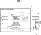
- a tool path generation device 10 includes, as main components, an input part 12, a storage part 14, a tool path generation part 16, and a coefficients calculation part 18.
- the tool path generated by the tool path generation part 16 is output to a machine tool 100.
- the machine tool 100 may be, for example, a machining center which includes a processing machine, such as a milling machine, having a rotatably supported spindle (not shown), a table (not shown) on which a workpiece 108 is attached so as to face the spindle, and a feed device (not shown) for moving the spindle and/or the workpiece 108 relative to each other in at least the X, Y, and Z orthogonal triaxial directions, and an NC device for controlling the tool feeding of the processing machine.
- a processing machine such as a milling machine, having a rotatably supported spindle (not shown), a table (not shown) on which a workpiece 108 is attached so as to face the spindle, and a feed device (not shown) for moving the spindle and/or the workpiece 108 relative to each other in at least the X, Y, and Z orthogonal triaxial directions, and an NC device for controlling the tool feeding of the processing machine.
- the processing machine may be a lathe in which the workpiece 108 is attached to the rotatably supported spindle and a tool is attached a tool post (not shown), wherein the feed device which causes the relative movement of the tool post in the X, Y, and Z orthogonal triaxial directions is controlled by an NC device.
- the machine tool 100 includes a measuring instrument 102 for measuring the machined surface of the machined workpiece W. The measurement results produced by the measuring instrument 102 are transmitted to a coefficients calculation part 18.
- the input part 12 may be a keyboard, a touch panel or the like using which mathematical expressions and numerical values may be input to the storage part 14.
- the function obtained from the polynomial expression including a plurality of coefficients defining a surface formed on the workpiece 108 and various numerical values of the plurality of coefficients are input to the storage part 14 via the input part 12.
- the storage part 14 may be a flash memory or a hard drive and includes at least a function storage area 20 for storing the aforementioned function and numerical values input from the input part 12, and a coefficients storage area 22.
- the tool path generation part 16 generates a tool path or NC data based on the function and the numerical values of the coefficients of the function stored in the storage part 14 and transmits the tool path stored in the storage part 14 or NC data to the NC device of the machine tool 100 at predetermined time intervals.
- the machine tool 100 machines the workpiece by moving the tool relative to the workpiece along the tool path transmitted to the NC device.
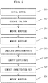
- a first function and numerical values of the coefficients of the first function are input to the storage part 14 via the input part 12 and initial setting is performed (step S10).
- the first function may be set as a polynomial expression including a plurality of coefficients defining a curved surface which to be formed on the workpiece 108.
- C is the curvature and K is the conic constant.
- a through D are aspherical coefficients which are input from the input part 12 in the initial setting of step S10. Further, the aspherical coefficients A through D are calculated and modified by the coefficients calculation part 18, as described later.
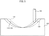
- the central axis direction of the ball end mill 106 is defined as the Z axis and the directions perpendicular to the Z axis are defined as the X axis and Y axis.
- the measuring instrument 102 can include a touch sensor having a probe 104 which may be mounted on the end of the spindle of the machine tool 100.
- a skip signal is generated from the measuring instrument 102, and the X axis, Y axis and Z axis coordinates of the feed device of the machine tool 100 can be output to the coefficients calculation part 18 with the skip signal as a trigger.
- the machined surface 110 is measured at a plurality of measurement points therealong and the X, Y, and Z coordinates of each measurement point are output to the coefficients calculation part 18.
- the design surface 120 is an aspherical surface represented by Formula (1) and the optical axis of the formed lens is parallel to the Z axis.
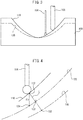
- the machined surface 110 does not completely coincide with the design surface 120 and includes an error 8z that is a difference in the Z axis direction between the measurement points 112 on the machined surface 110 and the design surface 120.
- ⁇ z is a positive value indicating that cutting was insufficient, but ⁇ z may be a negative value indicating that excessive cutting has been performed.
- a virtual curved surface (second curved surface) that best fits the coordinate data group of the series of correction points 132 is determined.
- the second curved surface which is the virtual curved surface, is defined by a function similar to Formula (1) obtained by correcting the aspherical coefficients A to D of Formula (1) by the coefficients calculation part 18 based on the coordinate data group of the measurement points 112 measured by the measuring instrument 102, as described below (step S20).
- Formula (1) in which the aspherical coefficients A to D have been corrected becomes the second function.
- the tool path generation part 16 generates a second tool path based on the function stored in the function storage area 20 and the corrected aspherical coefficients A to D calculated by the coefficients calculation part 18 and stored in the coefficients storage area 22, i.e., based on the second function (step S22).
- the machine tool 11 machines the workpiece 108 along the second tool path (step S24).
- the formula expressing the shape of the optical components already includes the aspherical coefficients A to D for correcting optical characteristics.
- the aspherical coefficients A to D can be used as the coefficients a 1 to a N for correction.
- Such a case can be compensated for by replacing the coefficient vector "a" subsequent thereto with a difference of each of aspherical coefficients A to D from the designated value.
- Machining of the workpiece 108 in step S14 is machining of the curved surface when coefficient vector "a" is a zero vector.
- function f and function F are equal.
- f p ⁇ F p ⁇ 0 ⁇
- the group r of measurement points 112 which is a collection of points in three-dimensional space, are converted to points consisting of points in the parameter space (u-v space) and signed distances.
- the signed distance is a real number representing the distance from the point in three-dimensional space corresponding to the point in the parameter space (u-v space), wherein the distance in the normal direction is positive and the distance in the direction opposite to the normal direction is negative.
- This conversion can be processed by, for example, the following.
- points are generated in a lattice in the parameter space (u-v space) representing the design surface or the first curved surface (process I).
- process II each point generated by process I is converted into a point in three-dimensional space and is correlated therewith (process II).
- a data structure such as a k-d tree (k-dimensional tree) with respect to the points in three-dimensional space converted by process II is generated.
- k-d tree k-dimensional tree
- one of the measurement points 112 is set as a processing target point q (refer to Figures 6 and 7 ).
- a point closer to the target point q from among the points in three-dimensional space converted by the above process II is searched and set as q 1 .
- the corresponding point in the parameter space (u-v space) is p 1 .
- q 1 ⁇ f p 1 ⁇
- ⁇ u, ⁇ v, and ⁇ n are represented as follows.
- ⁇ u c ⁇ d v ⁇ l v ⁇ d u c 2 ⁇ l u 2 ⁇ l v 2
- ⁇ v c ⁇ d u ⁇ l v ⁇ d v c 2 ⁇ l u 2 ⁇ l v 2
- the measurement points 112 are converted into points in the parameter space and signed distances by the above processing.
- the converted point group is represented as R below.
- n is a normal vector
- the correction amount is normally a very small value, and the change in the normal direction due to the correction is often negligible in many cases.
- the normal direction instead of calculating the normal direction each time, the normal direction can be stored as calculated by equation (4) and used for the calculation.
- Equation (8) is a sum of squares minimization problem, it can be calculated by, for example, the Levenberg-Marquardt method. If the coefficient "a" that minimizes the function E is found, a corrected function (second function) can be obtained by substituting the coefficient "a" into function F.
Landscapes
- Engineering & Computer Science (AREA)
- Human Computer Interaction (AREA)
- Manufacturing & Machinery (AREA)
- Physics & Mathematics (AREA)
- General Physics & Mathematics (AREA)
- Automation & Control Theory (AREA)
- Numerical Control (AREA)
Claims (3)
- Werkzeugpfaderzeugungsverfahren zum Erzeugen eines Werkzeugpfads auf der Grundlage einer Funktion, die eine gekrümmte Oberfläche in einem dreidimensionalen Raum definiert, wobei das Verfahren die folgenden Schritte umfasst:Eingeben einer ersten von einem Polynomausdruck, der eine Vielzahl von Koeffizienten enthält, abgeleiteten Funktion, die eine erste gekrümmte Oberfläche darstellt,Erzeugen eines ersten Werkzeugpfads auf der Grundlage der ersten Funktion;Eingeben des ersten Werkzeugpfads in eine NC-Vorrichtung einer Werkzeugmaschine (100) und Bearbeiten eines Werkstücks (108) durch eine Relativbewegung zwischen einem Werkzeug und dem Werkstück (108) entlang des ersten Werkzeugpfads;Messen der Form des Werkstücks (108) an einer Vielzahl von Messpunkten (112) auf einer Oberfläche (110) des bearbeiteten Werkstücks (108);Berechnen, für jeden der Messpunkte (112), einer symmetrischen Position in Bezug auf die erste gekrümmte Oberfläche in einer Richtung senkrecht zu der ersten gekrümmten Oberfläche als ein Korrekturpunkt (132);Erhalten einer zweiten Funktion, die eine zweite gekrümmte Oberfläche darstellt, auf der Grundlage einer Reihe von Positionsdaten der Korrekturpunkte (132), wobei die zweite Funktion durch ein Ändern der Vielzahl von Koeffizienten der ersten Funktion definiert ist; undErzeugen eines zweiten Werkzeugpfads auf der Grundlage der zweiten Funktion.
- Werkzeugpfaderzeugungsverfahren gemäß Anspruch 1, wobei die zweite Funktion auf der Grundlage der Reihe von Positionsdaten der Korrekturpunkte (132) unter Verwendung der Methode der kleinsten Quadrate erhalten wird.
- Werkzeugpfaderzeugungsverfahren nach einem der Ansprüche 1 oder 2, wobei die erste und die zweite Funktion im Allgemeinen durch die folgende Formel ausgedrückt werden:

Applications Claiming Priority (1)
| Application Number | Priority Date | Filing Date | Title |
|---|---|---|---|
| PCT/JP2015/082151 WO2017085768A1 (ja) | 2015-11-16 | 2015-11-16 | 工具経路生成方法 |
Publications (3)
| Publication Number | Publication Date |
|---|---|
| EP3379353A1 EP3379353A1 (de) | 2018-09-26 |
| EP3379353A4 EP3379353A4 (de) | 2019-07-24 |
| EP3379353B1 true EP3379353B1 (de) | 2020-07-22 |
Family
ID=58718474
Family Applications (1)
| Application Number | Title | Priority Date | Filing Date |
|---|---|---|---|
| EP15908708.9A Active EP3379353B1 (de) | 2015-11-16 | 2015-11-16 | Verfahren zur erzeugung von werkzeugwegen |
Country Status (5)
| Country | Link |
|---|---|
| US (1) | US10599124B2 (de) |
| EP (1) | EP3379353B1 (de) |
| JP (1) | JP6567073B2 (de) |
| CN (1) | CN108351634B (de) |
| WO (1) | WO2017085768A1 (de) |
Families Citing this family (5)
| Publication number | Priority date | Publication date | Assignee | Title |
|---|---|---|---|---|
| US11806877B2 (en) * | 2018-02-08 | 2023-11-07 | Abb Schweiz Ag | Method and apparatus for adjusting robot motion path |
| CN109947045B (zh) * | 2019-03-27 | 2021-09-10 | 南京工业大学 | 一种基于极坐标机床的免校正数控倒角算法 |
| US11745305B2 (en) * | 2019-07-05 | 2023-09-05 | Moore Nanotechnology Systems, LLC | System and method for correcting machining error during a precision jig grinding process |
| CN114101741B (zh) * | 2021-12-01 | 2022-10-14 | 北京星航机电装备有限公司 | 一种数控加工在线检测及自动补偿的方法 |
| CN117102899B (zh) * | 2023-10-20 | 2024-01-09 | 浙江大学 | 基于超精密伺服加工系统的曲面光栅加工装置及加工方法 |
Family Cites Families (18)
| Publication number | Priority date | Publication date | Assignee | Title |
|---|---|---|---|---|
| JPH0815701B2 (ja) * | 1993-05-17 | 1996-02-21 | 株式会社エフ・エーラボ | 三次元加工方法 |
| US5946142A (en) | 1995-12-11 | 1999-08-31 | Hitachi Ltd. | Projection lens system and projection image display apparatus using the same |
| JP3381497B2 (ja) * | 1995-12-11 | 2003-02-24 | 株式会社日立製作所 | 投写用レンズ装置及びこれを用いた背面投写型画像ディスプレイ装置 |
| JP3662087B2 (ja) * | 1997-02-26 | 2005-06-22 | オリンパス株式会社 | 曲面切削加工方法 |
| JP4461256B2 (ja) * | 2005-02-28 | 2010-05-12 | 国立大学法人東京農工大学 | 表面加工制御方法、及び表面加工制御プログラム |
| CN100437601C (zh) * | 2006-07-24 | 2008-11-26 | 西安飞机工业(集团)有限责任公司 | 一种用于自动钻铆托架变形的修补数据处理方法 |
| US7463425B1 (en) * | 2007-07-17 | 2008-12-09 | Zoom Precision Optical Electronic Co., Ltd. | Zoom lens system |
| CN100585522C (zh) * | 2007-07-20 | 2010-01-27 | 天津大学 | 一种带有金刚石刀具前角补偿的超精密车削方法 |
| GB2452091B (en) * | 2007-08-24 | 2013-01-02 | Zeeko Ltd | Computer controlled work tool apparatus and method |
| JP2009136937A (ja) * | 2007-12-04 | 2009-06-25 | Olympus Corp | 加工方法、加工プログラム、加工装置 |
| JP5426153B2 (ja) * | 2008-12-17 | 2014-02-26 | ファナック株式会社 | 回転軸を有する工作機械用の数値制御装置 |
| JP2012035399A (ja) * | 2010-08-11 | 2012-02-23 | Shin Nippon Koki Co Ltd | 補正マトリクス導出装置、誤差補正装置及び工作機械 |
| JP2012088601A (ja) | 2010-10-21 | 2012-05-10 | Canon Inc | 光学素子の製造方法及びそれより製造された光学素子 |
| CN102078968B (zh) * | 2011-01-20 | 2012-06-20 | 天津大学 | 一种带有斜面的光学镜的超精密车削加工方法 |
| JP5342665B2 (ja) * | 2012-03-12 | 2013-11-13 | ファナック株式会社 | 渦巻き状計測経路に沿って計測を行うレンズ形状加工方法およびレンズ形状加工装置 |
| US9383742B2 (en) * | 2013-03-08 | 2016-07-05 | Pratt & Whitney Canada Corp. | System and method for positioning error compensation during manufacturing of complex-shaped gas turbine engine parts |
| CA2975871C (en) * | 2015-02-18 | 2023-04-18 | Xebec Technology Co., Ltd. | Path calculation program, processing device, path calculation method, tool, and processed article |
| CN104924633B (zh) * | 2015-04-30 | 2017-07-28 | 西北工业大学 | 一种用于成形槽形件的模具型面的设计方法 |
-
2015
- 2015-11-16 EP EP15908708.9A patent/EP3379353B1/de active Active
- 2015-11-16 US US15/775,176 patent/US10599124B2/en active Active
- 2015-11-16 WO PCT/JP2015/082151 patent/WO2017085768A1/ja not_active Ceased
- 2015-11-16 CN CN201580084570.6A patent/CN108351634B/zh not_active Expired - Fee Related
- 2015-11-16 JP JP2017551411A patent/JP6567073B2/ja active Active
Non-Patent Citations (1)
| Title |
|---|
| None * |
Also Published As
| Publication number | Publication date |
|---|---|
| CN108351634A (zh) | 2018-07-31 |
| WO2017085768A1 (ja) | 2017-05-26 |
| CN108351634B (zh) | 2021-02-26 |
| JP6567073B2 (ja) | 2019-08-28 |
| JPWO2017085768A1 (ja) | 2018-06-07 |
| EP3379353A1 (de) | 2018-09-26 |
| EP3379353A4 (de) | 2019-07-24 |
| US20180307197A1 (en) | 2018-10-25 |
| US10599124B2 (en) | 2020-03-24 |
Similar Documents
| Publication | Publication Date | Title |
|---|---|---|
| EP3379353B1 (de) | Verfahren zur erzeugung von werkzeugwegen | |
| KR101394004B1 (ko) | 소용돌이상 계측 경로를 따라 계측을 실시하는 렌즈 형상 가공 방법 및 렌즈 형상 가공 장치 | |
| Bi et al. | Adaptive machining for curved contour on deformed large skin based on on-machine measurement and isometric mapping | |
| Nojedeh et al. | Tool path accuracy enhancement through geometrical error compensation | |
| CN106709193B (zh) | 基于学习算法的航空发动机薄壁叶片加工误差补偿方法 | |
| CN104756027B (zh) | 加工装置的控制装置、加工装置和加工数据的校正方法 | |
| CN114549521A (zh) | 基于加工g代码引导的碳管阵蜂窝面形精度计算方法 | |
| JP5777184B2 (ja) | フォーミングマシン | |
| CN116339233B (zh) | 基于激光干涉跟踪仪测量场的机床误差控制方法及系统 | |
| Cheung et al. | Modelling and simulation of freeform surface generation in ultra-precision raster milling | |
| CN107003657A (zh) | 用于在数控机床上通过去屑工具对工件进行加工的方法 | |
| TWI645274B (zh) | 工件加工方法及其加工系統 | |
| CN120576682A (zh) | 一种光谱共焦传感器在机测量系统的光束矢量标定方法 | |
| Wang et al. | Using error equivalence concept to automatically adjust discrete manufacturing processes for dimensional variation control | |
| JP2007118100A (ja) | 回転軸対称曲面の加工方法、回転軸対称曲面加工装置 | |
| CN102441816B (zh) | 三维切削加工方法 | |
| Yao et al. | A finishing toolpath generation strategy for flank milling of ruled surface based on a Double-Point-Mirror method | |
| JP2005104093A (ja) | 回折光学素子の製造方法および回折光学素子 | |
| CN118377267A (zh) | 一种机理数据双驱动的复杂薄壁件加工让刀变形补偿方法 | |
| Khusainov et al. | Precision of surfaces machined on a lathe with geometric errors | |
| Mikó | Interpretation Workflow of Geometric Tolerances | |
| CN109765843B (zh) | 基于镜像法和三次样条插值的薄壁件加工误差补偿方法 | |
| Lee et al. | Improvement of product accuracy in freeform surface machining | |
| CN110968040A (zh) | 一种机械数控用加工轨迹的程序生成方法 | |
| CN119225276A (zh) | 腔体加工轨迹的确定方法、装置、电子设备及存储介质 |
Legal Events
| Date | Code | Title | Description |
|---|---|---|---|
| STAA | Information on the status of an ep patent application or granted ep patent |
Free format text: STATUS: THE INTERNATIONAL PUBLICATION HAS BEEN MADE |
|
| PUAI | Public reference made under article 153(3) epc to a published international application that has entered the european phase |
Free format text: ORIGINAL CODE: 0009012 |
|
| STAA | Information on the status of an ep patent application or granted ep patent |
Free format text: STATUS: REQUEST FOR EXAMINATION WAS MADE |
|
| 17P | Request for examination filed |
Effective date: 20180613 |
|
| AK | Designated contracting states |
Kind code of ref document: A1 Designated state(s): AL AT BE BG CH CY CZ DE DK EE ES FI FR GB GR HR HU IE IS IT LI LT LU LV MC MK MT NL NO PL PT RO RS SE SI SK SM TR |
|
| AX | Request for extension of the european patent |
Extension state: BA ME |
|
| DAV | Request for validation of the european patent (deleted) | ||
| DAX | Request for extension of the european patent (deleted) | ||
| A4 | Supplementary search report drawn up and despatched |
Effective date: 20190621 |
|
| RIC1 | Information provided on ipc code assigned before grant |
Ipc: G05B 19/401 20060101AFI20190614BHEP |
|
| REG | Reference to a national code |
Ref country code: DE Ref legal event code: R079 Ref document number: 602015056367 Country of ref document: DE Free format text: PREVIOUS MAIN CLASS: G05B0019409300 Ipc: G05B0019401000 |
|
| GRAP | Despatch of communication of intention to grant a patent |
Free format text: ORIGINAL CODE: EPIDOSNIGR1 |
|
| STAA | Information on the status of an ep patent application or granted ep patent |
Free format text: STATUS: GRANT OF PATENT IS INTENDED |
|
| RIC1 | Information provided on ipc code assigned before grant |
Ipc: G05B 19/401 20060101AFI20200129BHEP |
|
| INTG | Intention to grant announced |
Effective date: 20200212 |
|
| GRAS | Grant fee paid |
Free format text: ORIGINAL CODE: EPIDOSNIGR3 |
|
| GRAA | (expected) grant |
Free format text: ORIGINAL CODE: 0009210 |
|
| STAA | Information on the status of an ep patent application or granted ep patent |
Free format text: STATUS: THE PATENT HAS BEEN GRANTED |
|
| AK | Designated contracting states |
Kind code of ref document: B1 Designated state(s): AL AT BE BG CH CY CZ DE DK EE ES FI FR GB GR HR HU IE IS IT LI LT LU LV MC MK MT NL NO PL PT RO RS SE SI SK SM TR |
|
| REG | Reference to a national code |
Ref country code: GB Ref legal event code: FG4D |
|
| REG | Reference to a national code |
Ref country code: CH Ref legal event code: EP |
|
| REG | Reference to a national code |
Ref country code: DE Ref legal event code: R096 Ref document number: 602015056367 Country of ref document: DE |
|
| REG | Reference to a national code |
Ref country code: AT Ref legal event code: REF Ref document number: 1293992 Country of ref document: AT Kind code of ref document: T Effective date: 20200815 |
|
| REG | Reference to a national code |
Ref country code: IE Ref legal event code: FG4D |
|
| REG | Reference to a national code |
Ref country code: LT Ref legal event code: MG4D |
|
| REG | Reference to a national code |
Ref country code: AT Ref legal event code: MK05 Ref document number: 1293992 Country of ref document: AT Kind code of ref document: T Effective date: 20200722 |
|
| PG25 | Lapsed in a contracting state [announced via postgrant information from national office to epo] |
Ref country code: ES Free format text: LAPSE BECAUSE OF FAILURE TO SUBMIT A TRANSLATION OF THE DESCRIPTION OR TO PAY THE FEE WITHIN THE PRESCRIBED TIME-LIMIT Effective date: 20200722 Ref country code: NO Free format text: LAPSE BECAUSE OF FAILURE TO SUBMIT A TRANSLATION OF THE DESCRIPTION OR TO PAY THE FEE WITHIN THE PRESCRIBED TIME-LIMIT Effective date: 20201022 Ref country code: GR Free format text: LAPSE BECAUSE OF FAILURE TO SUBMIT A TRANSLATION OF THE DESCRIPTION OR TO PAY THE FEE WITHIN THE PRESCRIBED TIME-LIMIT Effective date: 20201023 Ref country code: SE Free format text: LAPSE BECAUSE OF FAILURE TO SUBMIT A TRANSLATION OF THE DESCRIPTION OR TO PAY THE FEE WITHIN THE PRESCRIBED TIME-LIMIT Effective date: 20200722 Ref country code: FI Free format text: LAPSE BECAUSE OF FAILURE TO SUBMIT A TRANSLATION OF THE DESCRIPTION OR TO PAY THE FEE WITHIN THE PRESCRIBED TIME-LIMIT Effective date: 20200722 Ref country code: HR Free format text: LAPSE BECAUSE OF FAILURE TO SUBMIT A TRANSLATION OF THE DESCRIPTION OR TO PAY THE FEE WITHIN THE PRESCRIBED TIME-LIMIT Effective date: 20200722 Ref country code: AT Free format text: LAPSE BECAUSE OF FAILURE TO SUBMIT A TRANSLATION OF THE DESCRIPTION OR TO PAY THE FEE WITHIN THE PRESCRIBED TIME-LIMIT Effective date: 20200722 Ref country code: LT Free format text: LAPSE BECAUSE OF FAILURE TO SUBMIT A TRANSLATION OF THE DESCRIPTION OR TO PAY THE FEE WITHIN THE PRESCRIBED TIME-LIMIT Effective date: 20200722 Ref country code: BG Free format text: LAPSE BECAUSE OF FAILURE TO SUBMIT A TRANSLATION OF THE DESCRIPTION OR TO PAY THE FEE WITHIN THE PRESCRIBED TIME-LIMIT Effective date: 20201022 Ref country code: PT Free format text: LAPSE BECAUSE OF FAILURE TO SUBMIT A TRANSLATION OF THE DESCRIPTION OR TO PAY THE FEE WITHIN THE PRESCRIBED TIME-LIMIT Effective date: 20201123 |
|
| PG25 | Lapsed in a contracting state [announced via postgrant information from national office to epo] |
Ref country code: PL Free format text: LAPSE BECAUSE OF FAILURE TO SUBMIT A TRANSLATION OF THE DESCRIPTION OR TO PAY THE FEE WITHIN THE PRESCRIBED TIME-LIMIT Effective date: 20200722 Ref country code: LV Free format text: LAPSE BECAUSE OF FAILURE TO SUBMIT A TRANSLATION OF THE DESCRIPTION OR TO PAY THE FEE WITHIN THE PRESCRIBED TIME-LIMIT Effective date: 20200722 Ref country code: RS Free format text: LAPSE BECAUSE OF FAILURE TO SUBMIT A TRANSLATION OF THE DESCRIPTION OR TO PAY THE FEE WITHIN THE PRESCRIBED TIME-LIMIT Effective date: 20200722 Ref country code: IS Free format text: LAPSE BECAUSE OF FAILURE TO SUBMIT A TRANSLATION OF THE DESCRIPTION OR TO PAY THE FEE WITHIN THE PRESCRIBED TIME-LIMIT Effective date: 20201122 |
|
| PG25 | Lapsed in a contracting state [announced via postgrant information from national office to epo] |
Ref country code: NL Free format text: LAPSE BECAUSE OF FAILURE TO SUBMIT A TRANSLATION OF THE DESCRIPTION OR TO PAY THE FEE WITHIN THE PRESCRIBED TIME-LIMIT Effective date: 20200722 |
|
| REG | Reference to a national code |
Ref country code: DE Ref legal event code: R097 Ref document number: 602015056367 Country of ref document: DE |
|
| PG25 | Lapsed in a contracting state [announced via postgrant information from national office to epo] |
Ref country code: RO Free format text: LAPSE BECAUSE OF FAILURE TO SUBMIT A TRANSLATION OF THE DESCRIPTION OR TO PAY THE FEE WITHIN THE PRESCRIBED TIME-LIMIT Effective date: 20200722 Ref country code: SM Free format text: LAPSE BECAUSE OF FAILURE TO SUBMIT A TRANSLATION OF THE DESCRIPTION OR TO PAY THE FEE WITHIN THE PRESCRIBED TIME-LIMIT Effective date: 20200722 Ref country code: EE Free format text: LAPSE BECAUSE OF FAILURE TO SUBMIT A TRANSLATION OF THE DESCRIPTION OR TO PAY THE FEE WITHIN THE PRESCRIBED TIME-LIMIT Effective date: 20200722 Ref country code: DK Free format text: LAPSE BECAUSE OF FAILURE TO SUBMIT A TRANSLATION OF THE DESCRIPTION OR TO PAY THE FEE WITHIN THE PRESCRIBED TIME-LIMIT Effective date: 20200722 Ref country code: CZ Free format text: LAPSE BECAUSE OF FAILURE TO SUBMIT A TRANSLATION OF THE DESCRIPTION OR TO PAY THE FEE WITHIN THE PRESCRIBED TIME-LIMIT Effective date: 20200722 |
|
| PLBE | No opposition filed within time limit |
Free format text: ORIGINAL CODE: 0009261 |
|
| STAA | Information on the status of an ep patent application or granted ep patent |
Free format text: STATUS: NO OPPOSITION FILED WITHIN TIME LIMIT |
|
| PG25 | Lapsed in a contracting state [announced via postgrant information from national office to epo] |
Ref country code: AL Free format text: LAPSE BECAUSE OF FAILURE TO SUBMIT A TRANSLATION OF THE DESCRIPTION OR TO PAY THE FEE WITHIN THE PRESCRIBED TIME-LIMIT Effective date: 20200722 |
|
| 26N | No opposition filed |
Effective date: 20210423 |
|
| PG25 | Lapsed in a contracting state [announced via postgrant information from national office to epo] |
Ref country code: MC Free format text: LAPSE BECAUSE OF FAILURE TO SUBMIT A TRANSLATION OF THE DESCRIPTION OR TO PAY THE FEE WITHIN THE PRESCRIBED TIME-LIMIT Effective date: 20200722 Ref country code: SK Free format text: LAPSE BECAUSE OF FAILURE TO SUBMIT A TRANSLATION OF THE DESCRIPTION OR TO PAY THE FEE WITHIN THE PRESCRIBED TIME-LIMIT Effective date: 20200722 |
|
| REG | Reference to a national code |
Ref country code: CH Ref legal event code: PL |
|
| PG25 | Lapsed in a contracting state [announced via postgrant information from national office to epo] |
Ref country code: LU Free format text: LAPSE BECAUSE OF NON-PAYMENT OF DUE FEES Effective date: 20201116 |
|
| REG | Reference to a national code |
Ref country code: BE Ref legal event code: MM Effective date: 20201130 |
|
| PG25 | Lapsed in a contracting state [announced via postgrant information from national office to epo] |
Ref country code: CH Free format text: LAPSE BECAUSE OF NON-PAYMENT OF DUE FEES Effective date: 20201130 Ref country code: SI Free format text: LAPSE BECAUSE OF FAILURE TO SUBMIT A TRANSLATION OF THE DESCRIPTION OR TO PAY THE FEE WITHIN THE PRESCRIBED TIME-LIMIT Effective date: 20200722 Ref country code: LI Free format text: LAPSE BECAUSE OF NON-PAYMENT OF DUE FEES Effective date: 20201130 |
|
| REG | Reference to a national code |
Ref country code: NL Ref legal event code: MP Effective date: 20200722 |
|
| PG25 | Lapsed in a contracting state [announced via postgrant information from national office to epo] |
Ref country code: IE Free format text: LAPSE BECAUSE OF NON-PAYMENT OF DUE FEES Effective date: 20201116 |
|
| PG25 | Lapsed in a contracting state [announced via postgrant information from national office to epo] |
Ref country code: TR Free format text: LAPSE BECAUSE OF FAILURE TO SUBMIT A TRANSLATION OF THE DESCRIPTION OR TO PAY THE FEE WITHIN THE PRESCRIBED TIME-LIMIT Effective date: 20200722 Ref country code: MT Free format text: LAPSE BECAUSE OF FAILURE TO SUBMIT A TRANSLATION OF THE DESCRIPTION OR TO PAY THE FEE WITHIN THE PRESCRIBED TIME-LIMIT Effective date: 20200722 Ref country code: CY Free format text: LAPSE BECAUSE OF FAILURE TO SUBMIT A TRANSLATION OF THE DESCRIPTION OR TO PAY THE FEE WITHIN THE PRESCRIBED TIME-LIMIT Effective date: 20200722 |
|
| PG25 | Lapsed in a contracting state [announced via postgrant information from national office to epo] |
Ref country code: MK Free format text: LAPSE BECAUSE OF FAILURE TO SUBMIT A TRANSLATION OF THE DESCRIPTION OR TO PAY THE FEE WITHIN THE PRESCRIBED TIME-LIMIT Effective date: 20200722 |
|
| PG25 | Lapsed in a contracting state [announced via postgrant information from national office to epo] |
Ref country code: BE Free format text: LAPSE BECAUSE OF NON-PAYMENT OF DUE FEES Effective date: 20201130 |
|
| PGFP | Annual fee paid to national office [announced via postgrant information from national office to epo] |
Ref country code: GB Payment date: 20231109 Year of fee payment: 9 |
|
| PGFP | Annual fee paid to national office [announced via postgrant information from national office to epo] |
Ref country code: IT Payment date: 20231107 Year of fee payment: 9 Ref country code: FR Payment date: 20231027 Year of fee payment: 9 Ref country code: DE Payment date: 20231128 Year of fee payment: 9 |
|
| REG | Reference to a national code |
Ref country code: DE Ref legal event code: R119 Ref document number: 602015056367 Country of ref document: DE |
|
| GBPC | Gb: european patent ceased through non-payment of renewal fee |
Effective date: 20241116 |
|
| PG25 | Lapsed in a contracting state [announced via postgrant information from national office to epo] |
Ref country code: DE Free format text: LAPSE BECAUSE OF NON-PAYMENT OF DUE FEES Effective date: 20250603 |
|
| PG25 | Lapsed in a contracting state [announced via postgrant information from national office to epo] |
Ref country code: IT Free format text: LAPSE BECAUSE OF NON-PAYMENT OF DUE FEES Effective date: 20241116 |
|
| PG25 | Lapsed in a contracting state [announced via postgrant information from national office to epo] |
Ref country code: GB Free format text: LAPSE BECAUSE OF NON-PAYMENT OF DUE FEES Effective date: 20241116 |
|
| PG25 | Lapsed in a contracting state [announced via postgrant information from national office to epo] |
Ref country code: FR Free format text: LAPSE BECAUSE OF NON-PAYMENT OF DUE FEES Effective date: 20241130 |