EP3379359B1 - Algorithme non supervisé guidé par les données pour analyser des données de capteur pour détecter un fonctionnement de valve anormal - Google Patents
Algorithme non supervisé guidé par les données pour analyser des données de capteur pour détecter un fonctionnement de valve anormal Download PDFInfo
- Publication number
- EP3379359B1 EP3379359B1 EP18155004.7A EP18155004A EP3379359B1 EP 3379359 B1 EP3379359 B1 EP 3379359B1 EP 18155004 A EP18155004 A EP 18155004A EP 3379359 B1 EP3379359 B1 EP 3379359B1
- Authority
- EP
- European Patent Office
- Prior art keywords
- shut
- sensor
- valve
- values
- parameters
- Prior art date
- Legal status (The legal status is an assumption and is not a legal conclusion. Google has not performed a legal analysis and makes no representation as to the accuracy of the status listed.)
- Active
Links
Images



Classifications
-
- G—PHYSICS
- G06—COMPUTING OR CALCULATING; COUNTING
- G06Q—INFORMATION AND COMMUNICATION TECHNOLOGY [ICT] SPECIALLY ADAPTED FOR ADMINISTRATIVE, COMMERCIAL, FINANCIAL, MANAGERIAL OR SUPERVISORY PURPOSES; SYSTEMS OR METHODS SPECIALLY ADAPTED FOR ADMINISTRATIVE, COMMERCIAL, FINANCIAL, MANAGERIAL OR SUPERVISORY PURPOSES, NOT OTHERWISE PROVIDED FOR
- G06Q10/00—Administration; Management
- G06Q10/10—Office automation; Time management
- G06Q10/109—Time management, e.g. calendars, reminders, meetings or time accounting
- G06Q10/1097—Time management, e.g. calendars, reminders, meetings or time accounting using calendar-based scheduling for task assignment
-
- G—PHYSICS
- G05—CONTROLLING; REGULATING
- G05B—CONTROL OR REGULATING SYSTEMS IN GENERAL; FUNCTIONAL ELEMENTS OF SUCH SYSTEMS; MONITORING OR TESTING ARRANGEMENTS FOR SUCH SYSTEMS OR ELEMENTS
- G05B23/00—Testing or monitoring of control systems or parts thereof
- G05B23/02—Electric testing or monitoring
- G05B23/0205—Electric testing or monitoring by means of a monitoring system capable of detecting and responding to faults
- G05B23/0218—Electric testing or monitoring by means of a monitoring system capable of detecting and responding to faults characterised by the fault detection method dealing with either existing or incipient faults
- G05B23/0221—Preprocessing measurements, e.g. data collection rate adjustment; Standardization of measurements; Time series or signal analysis, e.g. frequency analysis or wavelets; Trustworthiness of measurements; Indexes therefor; Measurements using easily measured parameters to estimate parameters difficult to measure; Virtual sensor creation; De-noising; Sensor fusion; Unconventional preprocessing inherently present in specific fault detection methods like PCA-based methods
-
- F—MECHANICAL ENGINEERING; LIGHTING; HEATING; WEAPONS; BLASTING
- F01—MACHINES OR ENGINES IN GENERAL; ENGINE PLANTS IN GENERAL; STEAM ENGINES
- F01D—NON-POSITIVE DISPLACEMENT MACHINES OR ENGINES, e.g. STEAM TURBINES
- F01D21/00—Shutting-down of machines or engines, e.g. in emergency; Regulating, controlling, or safety means not otherwise provided for
- F01D21/003—Arrangements for testing or measuring
-
- F—MECHANICAL ENGINEERING; LIGHTING; HEATING; WEAPONS; BLASTING
- F16—ENGINEERING ELEMENTS AND UNITS; GENERAL MEASURES FOR PRODUCING AND MAINTAINING EFFECTIVE FUNCTIONING OF MACHINES OR INSTALLATIONS; THERMAL INSULATION IN GENERAL
- F16K—VALVES; TAPS; COCKS; ACTUATING-FLOATS; DEVICES FOR VENTING OR AERATING
- F16K37/00—Special means in or on valves or other cut-off apparatus for indicating or recording operation thereof, or for enabling an alarm to be given
- F16K37/0075—For recording or indicating the functioning of a valve in combination with test equipment
-
- F—MECHANICAL ENGINEERING; LIGHTING; HEATING; WEAPONS; BLASTING
- F16—ENGINEERING ELEMENTS AND UNITS; GENERAL MEASURES FOR PRODUCING AND MAINTAINING EFFECTIVE FUNCTIONING OF MACHINES OR INSTALLATIONS; THERMAL INSULATION IN GENERAL
- F16K—VALVES; TAPS; COCKS; ACTUATING-FLOATS; DEVICES FOR VENTING OR AERATING
- F16K37/00—Special means in or on valves or other cut-off apparatus for indicating or recording operation thereof, or for enabling an alarm to be given
- F16K37/0075—For recording or indicating the functioning of a valve in combination with test equipment
- F16K37/0083—For recording or indicating the functioning of a valve in combination with test equipment by measuring valve parameters
-
- G—PHYSICS
- G05—CONTROLLING; REGULATING
- G05B—CONTROL OR REGULATING SYSTEMS IN GENERAL; FUNCTIONAL ELEMENTS OF SUCH SYSTEMS; MONITORING OR TESTING ARRANGEMENTS FOR SUCH SYSTEMS OR ELEMENTS
- G05B23/00—Testing or monitoring of control systems or parts thereof
- G05B23/02—Electric testing or monitoring
- G05B23/0205—Electric testing or monitoring by means of a monitoring system capable of detecting and responding to faults
- G05B23/0218—Electric testing or monitoring by means of a monitoring system capable of detecting and responding to faults characterised by the fault detection method dealing with either existing or incipient faults
- G05B23/0224—Process history based detection method, e.g. whereby history implies the availability of large amounts of data
- G05B23/0227—Qualitative history assessment, whereby the type of data acted upon, e.g. waveforms, images or patterns, is not relevant, e.g. rule based assessment; if-then decisions
- G05B23/0235—Qualitative history assessment, whereby the type of data acted upon, e.g. waveforms, images or patterns, is not relevant, e.g. rule based assessment; if-then decisions based on a comparison with predetermined threshold or range, e.g. "classical methods", carried out during normal operation; threshold adaptation or choice; when or how to compare with the threshold
-
- G—PHYSICS
- G05—CONTROLLING; REGULATING
- G05B—CONTROL OR REGULATING SYSTEMS IN GENERAL; FUNCTIONAL ELEMENTS OF SUCH SYSTEMS; MONITORING OR TESTING ARRANGEMENTS FOR SUCH SYSTEMS OR ELEMENTS
- G05B23/00—Testing or monitoring of control systems or parts thereof
- G05B23/02—Electric testing or monitoring
- G05B23/0205—Electric testing or monitoring by means of a monitoring system capable of detecting and responding to faults
- G05B23/0218—Electric testing or monitoring by means of a monitoring system capable of detecting and responding to faults characterised by the fault detection method dealing with either existing or incipient faults
- G05B23/0224—Process history based detection method, e.g. whereby history implies the availability of large amounts of data
- G05B23/024—Quantitative history assessment, e.g. mathematical relationships between available data; Functions therefor; Principal component analysis [PCA]; Partial least square [PLS]; Statistical classifiers, e.g. Bayesian networks, linear regression or correlation analysis; Neural networks
-
- G—PHYSICS
- G05—CONTROLLING; REGULATING
- G05B—CONTROL OR REGULATING SYSTEMS IN GENERAL; FUNCTIONAL ELEMENTS OF SUCH SYSTEMS; MONITORING OR TESTING ARRANGEMENTS FOR SUCH SYSTEMS OR ELEMENTS
- G05B23/00—Testing or monitoring of control systems or parts thereof
- G05B23/02—Electric testing or monitoring
- G05B23/0205—Electric testing or monitoring by means of a monitoring system capable of detecting and responding to faults
- G05B23/0259—Electric testing or monitoring by means of a monitoring system capable of detecting and responding to faults characterized by the response to fault detection
- G05B23/0283—Predictive maintenance, e.g. involving the monitoring of a system and, based on the monitoring results, taking decisions on the maintenance schedule of the monitored system; Estimating remaining useful life [RUL]
-
- G—PHYSICS
- G06—COMPUTING OR CALCULATING; COUNTING
- G06Q—INFORMATION AND COMMUNICATION TECHNOLOGY [ICT] SPECIALLY ADAPTED FOR ADMINISTRATIVE, COMMERCIAL, FINANCIAL, MANAGERIAL OR SUPERVISORY PURPOSES; SYSTEMS OR METHODS SPECIALLY ADAPTED FOR ADMINISTRATIVE, COMMERCIAL, FINANCIAL, MANAGERIAL OR SUPERVISORY PURPOSES, NOT OTHERWISE PROVIDED FOR
- G06Q10/00—Administration; Management
- G06Q10/20—Administration of product repair or maintenance
-
- B—PERFORMING OPERATIONS; TRANSPORTING
- B64—AIRCRAFT; AVIATION; COSMONAUTICS
- B64F—GROUND OR AIRCRAFT-CARRIER-DECK INSTALLATIONS SPECIALLY ADAPTED FOR USE IN CONNECTION WITH AIRCRAFT; DESIGNING, MANUFACTURING, ASSEMBLING, CLEANING, MAINTAINING OR REPAIRING AIRCRAFT, NOT OTHERWISE PROVIDED FOR; HANDLING, TRANSPORTING, TESTING OR INSPECTING AIRCRAFT COMPONENTS, NOT OTHERWISE PROVIDED FOR
- B64F5/00—Designing, manufacturing, assembling, cleaning, maintaining or repairing aircraft, not otherwise provided for; Handling, transporting, testing or inspecting aircraft components, not otherwise provided for
- B64F5/60—Testing or inspecting aircraft components or systems
-
- F—MECHANICAL ENGINEERING; LIGHTING; HEATING; WEAPONS; BLASTING
- F01—MACHINES OR ENGINES IN GENERAL; ENGINE PLANTS IN GENERAL; STEAM ENGINES
- F01D—NON-POSITIVE DISPLACEMENT MACHINES OR ENGINES, e.g. STEAM TURBINES
- F01D21/00—Shutting-down of machines or engines, e.g. in emergency; Regulating, controlling, or safety means not otherwise provided for
-
- F—MECHANICAL ENGINEERING; LIGHTING; HEATING; WEAPONS; BLASTING
- F16—ENGINEERING ELEMENTS AND UNITS; GENERAL MEASURES FOR PRODUCING AND MAINTAINING EFFECTIVE FUNCTIONING OF MACHINES OR INSTALLATIONS; THERMAL INSULATION IN GENERAL
- F16K—VALVES; TAPS; COCKS; ACTUATING-FLOATS; DEVICES FOR VENTING OR AERATING
- F16K37/00—Special means in or on valves or other cut-off apparatus for indicating or recording operation thereof, or for enabling an alarm to be given
- F16K37/0075—For recording or indicating the functioning of a valve in combination with test equipment
- F16K37/0091—For recording or indicating the functioning of a valve in combination with test equipment by measuring fluid parameters
-
- G—PHYSICS
- G01—MEASURING; TESTING
- G01M—TESTING STATIC OR DYNAMIC BALANCE OF MACHINES OR STRUCTURES; TESTING OF STRUCTURES OR APPARATUS, NOT OTHERWISE PROVIDED FOR
- G01M15/00—Testing of engines
- G01M15/14—Testing gas-turbine engines or jet-propulsion engines
-
- G—PHYSICS
- G01—MEASURING; TESTING
- G01M—TESTING STATIC OR DYNAMIC BALANCE OF MACHINES OR STRUCTURES; TESTING OF STRUCTURES OR APPARATUS, NOT OTHERWISE PROVIDED FOR
- G01M99/00—Subject matter not provided for in other groups of this subclass
- G01M99/005—Testing of complete machines, e.g. washing-machines or mobile phones
-
- G—PHYSICS
- G05—CONTROLLING; REGULATING
- G05B—CONTROL OR REGULATING SYSTEMS IN GENERAL; FUNCTIONAL ELEMENTS OF SUCH SYSTEMS; MONITORING OR TESTING ARRANGEMENTS FOR SUCH SYSTEMS OR ELEMENTS
- G05B23/00—Testing or monitoring of control systems or parts thereof
- G05B23/02—Electric testing or monitoring
- G05B23/0205—Electric testing or monitoring by means of a monitoring system capable of detecting and responding to faults
-
- G—PHYSICS
- G05—CONTROLLING; REGULATING
- G05B—CONTROL OR REGULATING SYSTEMS IN GENERAL; FUNCTIONAL ELEMENTS OF SUCH SYSTEMS; MONITORING OR TESTING ARRANGEMENTS FOR SUCH SYSTEMS OR ELEMENTS
- G05B23/00—Testing or monitoring of control systems or parts thereof
- G05B23/02—Electric testing or monitoring
- G05B23/0205—Electric testing or monitoring by means of a monitoring system capable of detecting and responding to faults
- G05B23/0218—Electric testing or monitoring by means of a monitoring system capable of detecting and responding to faults characterised by the fault detection method dealing with either existing or incipient faults
-
- G—PHYSICS
- G05—CONTROLLING; REGULATING
- G05B—CONTROL OR REGULATING SYSTEMS IN GENERAL; FUNCTIONAL ELEMENTS OF SUCH SYSTEMS; MONITORING OR TESTING ARRANGEMENTS FOR SUCH SYSTEMS OR ELEMENTS
- G05B23/00—Testing or monitoring of control systems or parts thereof
- G05B23/02—Electric testing or monitoring
- G05B23/0205—Electric testing or monitoring by means of a monitoring system capable of detecting and responding to faults
- G05B23/0218—Electric testing or monitoring by means of a monitoring system capable of detecting and responding to faults characterised by the fault detection method dealing with either existing or incipient faults
- G05B23/0243—Electric testing or monitoring by means of a monitoring system capable of detecting and responding to faults characterised by the fault detection method dealing with either existing or incipient faults model based detection method, e.g. first-principles knowledge model
- G05B23/0254—Electric testing or monitoring by means of a monitoring system capable of detecting and responding to faults characterised by the fault detection method dealing with either existing or incipient faults model based detection method, e.g. first-principles knowledge model based on a quantitative model, e.g. mathematical relationships between inputs and outputs; functions: observer, Kalman filter, residual calculation, Neural Networks
-
- G—PHYSICS
- G05—CONTROLLING; REGULATING
- G05B—CONTROL OR REGULATING SYSTEMS IN GENERAL; FUNCTIONAL ELEMENTS OF SUCH SYSTEMS; MONITORING OR TESTING ARRANGEMENTS FOR SUCH SYSTEMS OR ELEMENTS
- G05B23/00—Testing or monitoring of control systems or parts thereof
- G05B23/02—Electric testing or monitoring
- G05B23/0205—Electric testing or monitoring by means of a monitoring system capable of detecting and responding to faults
- G05B23/0259—Electric testing or monitoring by means of a monitoring system capable of detecting and responding to faults characterized by the response to fault detection
-
- G—PHYSICS
- G07—CHECKING-DEVICES
- G07C—TIME OR ATTENDANCE REGISTERS; REGISTERING OR INDICATING THE WORKING OF MACHINES; GENERATING RANDOM NUMBERS; VOTING OR LOTTERY APPARATUS; ARRANGEMENTS, SYSTEMS OR APPARATUS FOR CHECKING NOT PROVIDED FOR ELSEWHERE
- G07C5/00—Registering or indicating the working of vehicles
- G07C5/08—Registering or indicating performance data other than driving, working, idle, or waiting time, with or without registering driving, working, idle or waiting time
- G07C5/0808—Diagnosing performance data
Definitions
- aspects described herein relate to valves in aircraft, and more specifically, to a method and system for detecting abnormal valve operation based on a data-driven, unsupervised algorithm for analyzing sensor data. Often, abnormal operation of valves in an aircraft is difficult and time consuming to diagnose. Furthermore, conventional approaches are targeted at diagnosing abnormal operation of a specific valve, or type of valve.
- the invention is directed to a computer-implemented method and a system as defined in the claims.
- aspects disclosed herein provide techniques to detect faults in shut-off valves in aircraft (or other types of vehicles) using an n-second window of sensor data related to the shut-off valves.
- the n-second window of sensor data is captured as part of parametric flight data.
- aspects disclosed herein use an unsupervised learning algorithm to analyze data provided by sensors on previous flights to identify data values (and associated parameters) that indicate that a shut-off valve is operating abnormally. Once the parameters and data values are identified, aspects disclosed herein analyze n-second windows of real-time flight data after a valve opens and/or closes during flight. If the n-second windows of real-time flight data indicate that a given valve is operating abnormally, aspects disclosed herein may generate an indication of the abnormal operation.
- the indication of abnormal operation is transmitted from the aircraft to a receiving station on the ground, where maintenance crews and other personnel are alerted to the abnormal operation.
- the indication includes a request to order a replacement valve for the valve that is operating abnormally. Doing so facilitates maintenance and repair of the aircraft prior to actual failure of the valve.
- the learning algorithm disclosed herein is data-driven, the learning algorithm is model-free and need not be tailored to the specifics of the architecture and schematics of a given airplane. Furthermore, the learning algorithm is unsupervised in that a user need not intervene to manually create labels for training data. Therefore, the learning algorithm is flexible and portable across all types of aircraft, aircraft subsystems, and subsystem components. While an aircraft is used as a reference example herein, the disclosure is equally applicable to all types of vehicles that include shut-off valves.
- FIG. 1 is a block diagram illustrating components of a system 100 which implements a data-driven, unsupervised algorithm for analyzing sensor data to detect abnormal valve operation, according to one aspect.
- the system 100 includes a plurality of aircraft subsystems 101 1-N , a computer 104, and a plurality of data stores 110 1-N .
- the aircraft subsystems 101 1-N are representative of different subsystems in an aircraft, and include a plurality of shut-off valves 102 1-N and a plurality of sensors 103 1-N .
- Examples of the aircraft subsystems 101 1-N include the economy cooling valve (ECV) subsystem, environmental control system (ECS), a fuel system, a pneumatic system, and the like.
- ECV economy cooling valve
- ECS environmental control system
- shut-off valve refers to a valve which operates in one of two states, namely an open state and a closed state.
- the shut-off valves 102 1-N regulate the flow of air, fuel, or any other type of liquid or gas in the subsystems 101 1-N .
- the sensors 103 1-N are physical devices which detect conditions, events, and changes in the respective subsystem 101 1-N , and generate corresponding data for storage in the data stores 110 1-N . Examples of the sensors 103 1-N include temperature sensors, pressure sensors, airspeed sensors, humidity sensors, altitude sensors, and the like.
- a temperature sensor 103 1 detects a 30° air temperature when a shut-off valve 102 1 is closed, the temperature sensor 103 1 converts the temperature reading to a digital format, and transmits an indication of the detected temperature to the data stores 110 1-N for storage in the flight data 111.
- the data stores 110 1-N are representative of any type of system which stores parametric flight data, such as the Flight Data Recorder (FDR), Quick Access Record (QAR), Continuous Parameter Logging System (CPL), and the Enhanced Airborne Flight Recorder (EAFR).
- each data store 110 1-N includes stores of flight data 111 and a data store of maintenance messages (MMSGs) 112.
- the flight data 111 stores parametric flight data describing the operation of the associated aircraft.
- parametric flight data is a collection of time-series data collected during operation of an aircraft.
- the parameters of the parametric flight data include, without limitation, parameters describing the altitude of the aircraft, speed of the aircraft, temperature data, pressure data, and the like.
- the flight data 111 stores data values for a plurality of parameters generated by the sensors 103 1-N , such as a state of each shut-off valve 102 1-N (e.g., open or closed), as well as other sampled values, such as temperature, pressure, humidity readings, and the like.
- the shut-off valves 102 1-N transmit their respective state (e.g., open or closed) to the flight data 111.
- the maintenance messages stored in the MMSGs 112 are generated responsive to abnormal operations of the aircraft or any component thereof.
- a sensor 103 N records an air temperature of 100° C proximate to one of the shut-off valves 102 N , exceeding an example temperature threshold of 80° C.
- the sensor 103 N and/or a designated component of the aircraft generates an MMSG based on the recorded temperature, which is then stored in the MMSGs 112.
- Each MMSG 112 is associated with metadata parameters such as a respective timestamp, one or more recorded parameters (e.g., temperature) that exceed an associated rule, an affected component of the aircraft (e.g., one or more shut-off valves 102 1-N ), and the like.
- the computer 104 includes the abnormal operation module 105 and the thresholds 113.
- the abnormal operation module 105 is an application configured to detect abnormal operation of the shut-off valves 102 1-N .
- the abnormal operation module 105 implements an unsupervised learning algorithm which analyzes historical parametric flight data in the data stores 110 1-N (for one or more aircraft) to identify the parameters provided by the sensors 103 1-N that are relevant to detecting abnormal behavior in the shut-off valves 102 1-N .
- the abnormal operation module 105 determines, for each identified parameter, a corresponding threshold value which indicates that a given shut-off valve 102 1-N is operating abnormally (or will begin operating abnormally).
- the abnormal operation module 105 may then store the identified parameters and associated threshold values in the thresholds 113.
- the abnormal operation module 105 can analyze the data stores 110 1-N in real-time during subsequent flights (of the same or other similar aircraft), and determine whether the sensors 103 1-N are providing data values for the identified parameters that exceed the corresponding threshold. If the abnormal operation module 105 determines that the data values for the identified threshold exceed the corresponding thresholds, the abnormal operation module 105 determines that the associated shut-off valve(s) 102 1-N is operating abnormally. The abnormal operation module 105 then generates an indication (e.g., an alert) specifying which of the shut-off valves 102 1-N are operating abnormally. In one aspect, the indication includes the associated parametric data from the data stores 110 1-N which reflect that the shut-off valves 102 1-N are operating abnormally.
- a maintenance crew may order the parts necessary to repair and/or replace the abnormally operating shut-off valves 102 1-N before the plane lands, resulting in quicker turn-around, avoidance of delays, and cost savings.
- a user defines an initial set of parameters provided as input to the abnormal operation module 105.
- the initial set of parameters includes parameters from the QAR, FDL, CPL, and/or EAFR.
- such parameters may include temperature parameters, pressure parameters, and airflow parameters measured by the sensors 103 1-N .
- the user also defines one or more flight phases provided as input to the abnormal operation module 105.
- Example flight phases include taxi, takeoff, initial climb, landing, and the like.
- the abnormal operation module 105 analyzes the parametric flight data 111 that is associated with the specified flight phases, rather than all of the parametric flight data for the initial set of parameters.
- the abnormal operation module 105 performs an analysis of the flight data 111 to identify a subset of the initial set of parameters that are relevant to determining that a shut-off valve 102 1-N is operating abnormally. Furthermore, the abnormal operation module 105 computes a threshold value for each parameter in the subset. To do so, the abnormal operation module 105 determines, based on the flight data 111, when a given shut-off valve 102 N previously opened and closed. Generally, the flight data 111 includes a corresponding record reflecting each time one of the shut-off valves 102 1-N opens or closes. The abnormal operation module 105 then obtains, for each open and close event of the shut-off valve 102 N , an n-second window of values for each parameter in in the initial set of parameters.
- the n-second window may be of any length, such as 60 seconds, 120 seconds, and the like, and may be specified by the user, or be a predefined value coded in the abnormal operation module 105.
- the abnormal operation module 105 identifies, for each parameter in the initial set of parameters, a maximum value during each n-second interval.
- the abnormal operation module 105 then computes, for each variable, a difference between the maximum value of an n-second interval after an open of the shut-off valve 102 N and the maximum value of an n-second window after the next close of the same shut-off valve 102 N .
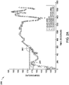
- FIG. 2A depicts a graph 200 generated from example temperature values stored in the flight data 111.
- the y-axis of the graph 200 corresponds to temperature values for a temperature parameter (e.g., in the initial set of parameters) recorded by a sensor 103 N associated with a shut-off valve 102 N .
- the x-axis of the graph is associated with time.
- the temperature value is approximately 155 degrees Celsius when the shut-off valve 102 N opens at 0 seconds.
- the maximum value of the n-second interval 120 seconds in this example
- the maximum observed temperature of approximately 174 degrees Celsius occurs at point 202.
- the difference between maximum parameter values is referred to herein as a "max_diff" value.
- the abnormal operation module 105 computes max_diff values for each parameter in the initial set of parameters and for each open and close of a given shut-off valve 102 N .
- the abnormal operation module 105 then performs a further analysis to identify the subset of the initial set of parameters that are associated with abnormal operation for a given shut-off valve 102 N (and similar or identical shut-off valves 102 1-N ).
- the abnormal operation module 105 computes, for each parameter in the initial set of parameters, a corresponding percentile threshold value for each computed max_diff value.
- the percentile threshold value is three standard deviations of the computed max_diff values for the associated parameter.
- an example percentile threshold max_diff value of 21 degrees is computed by the abnormal operation module 105, where 21 degrees represents the 95 th percentile (or three standard deviations) of all max_diff values computed for the temperature parameter.
- a predefined time period e.g., within 7 days, 14 days, 24 days, etc.
- the abnormal operation module 105 If the current max_diff value occurred within the predefined time period, the abnormal operation module 105 considers the current max_diff value as a true positive. Otherwise, the abnormal operation module 105 considers the current max_diff value as a false positive. Generally, the abnormal operation module 105 computes a ratio of false positives to true positives for each max_diff value (e.g., 22.0, 22.1, 22.2, ... , 24.8, 24.9, 25.0). The abnormal operation module 105 then defines the threshold for the parameter. In one aspect, the abnormal operation module 105 defines the threshold as the max_diff value that has the lowest computed ratio of false positives to true positives.
- the abnormal operation module 105 would define 22.2 as the threshold for the temperature parameter.
- the abnormal operation module 105 defines the threshold as the max_diff value that occurs within the predefined time period of each identified MMSG associated with a shut-off valve 102 1-N .
- the abnormal operation module 105 defines 22.5 as the threshold value for the temperature parameter. The abnormal operation module 105 then saves the threshold value and an indication of the parameter in the thresholds 113. Doing so includes the parameter as a member of the subset of the initial set of parameters.
- Figure 2B depicts a graph 250 which includes the computed max_diff temperature values as the y-axis, and time as the x-axis, according to one aspect.
- the graph 250 includes an example threshold max_diff value 251 computed by the abnormal operation module 105 as described above.
- the threshold max_diff value 251 is approximately 19 degrees.
- the graph 250 includes vertical lines 252-256, each of which corresponds to an MMSG in the MMSGs 112. Further still, example max_diff values 261-266 are labeled in the graph 250, to note the proximity to each MMSG line 252-256.
- the abnormal operation module 105 computes the threshold value 251 as the value which is associated with the lowest ratio of false positives to true positives (based on the proximity in time to a given MMSG). For example, if the abnormal operation module 105 detects one false positive and ten true positives, the computed ratio is 0.1. In another aspect, the abnormal operation module 105 defines the threshold value 251 based on the max_diff value which captures all MMSGs (e.g., each instance of a max_diff value above the threshold is within the predefined time period (e.g., 24 days) of a given MMSG 252-256.
- the abnormal operation module 105 discards these parameters, as these parameters often do not have max_diff values that are associated with any (or very few) true positives. Therefore, the ratio of false positives to true positives is undefined (due to division by zero), or very large. As such, the abnormal operation module 105 discards any such parameters. For example, in one aspect, the abnormal operation module 105 discards parameters whose ratio of false positives to true positives exceeds a relevance threshold, or those parameters whose ratio is undefined.
- the abnormal operation module 105 defines the subset of the initial set of parameters as those parameters whose max_diff values are responsible for abnormal operation of shut-off valves 102 1-N as reflected by the association of these values and MMSGs in the MMSGs 112.
- the abnormal operation module 105 uses the subset and corresponding threshold values to determine whether flight data 111 captured in real-time during a flight reflects that a shut-off valve 102 1-N is operating abnormally.
- the sensors 103 1-N provide parametric flight data to the flight data 111.
- the abnormal operation module 105 identifies n-second windows of parametric flight data for the parameters in the subset of parameters defined in the thresholds 113.
- the abnormal operation module 105 then computes a max_diff value for each parameter in the subset of parameters for each n-second window after an open and close (or close and open). In one example, the abnormal operation module 105 computes max_diff temperature values, pressure values, and the like based on the n-second windows of data captured by the sensors 103 1-N . If the computed max_diff value exceeds the corresponding threshold, the abnormal operation module 105 determines that the corresponding shut-off valve 102 N is operating abnormally.
- the abnormal operation module 105 determines that the max_diff value of 28 exceeds the example threshold of 19 degrees depicted in Figure 2B . As such, the abnormal operation module 105 determines that the associated shut-off valve 102 N is operating abnormally (or is faulty). In one aspect, the abnormal operation module 105 then generates an indication specifying that the shut-off valve 102 N is faulty. In one aspect, the abnormal operation module 105 transmit the indication from the aircraft to a remote system, which allows maintenance crews to obtain replacement parts, schedule repairs, and the like.
- the computer 104 executing the abnormal operation module 105 is an external system which receives the flight data 111 and MMSGs 112 from a plurality of different aircraft (e.g., via a network connection). Therefore, in such embodiments, the abnormal operation module 105 leverages flight data 111 and MMSGs 112 from these different aircraft when identifying relevant parameters in the subset of parameters, and determining the associated thresholds which reflect a given shut-off valve is operating abnormally. In such aspects, the abnormal operation module 105 executing on the remote computer 104 can receive real-time flight data from a plurality of different aircraft, and determine whether a given aircraft has a shut-off valve 102 N that is operating abnormally.
- Figure 3 is a flow chart illustrating a method 300 for detecting abnormal operation of shut-off valves based on a data-driven, unsupervised algorithm for analyzing sensor data, according to one aspect.
- the method 300 begins at block 310, where a user defines the initial set of parameters and any applicable flight phases. Doing so allows the abnormal operation module 105 to operate on an initial subset of the thousands or millions of parameters stored in the flight data 111.
- the abnormal operation module 105 receives parametric flight data 111.
- the parametric flight data 111 is generated by the shut-off valves 102 1-N and sensors 103 1-N .
- the received flight data 111 reflects flight data 111 captured on multiple flight legs. In at least one aspect, the received flight data 111 further reflects flight data 111 captured by multiple aircraft.
- the abnormal operation module 105 analyzes the flight data. Generally, at block 330, the abnormal operation module 105 computes max_diff values for the parameters in the flight data 111. At block 340, which occurs in parallel with block 330 in one aspect, the abnormal operation module 105 identifies the target MMSGs in the MMSGs 112. Generally, the target MMSGs are those MMSGs that are associated with abnormal operation of shut-off valves 102 1-N .
- the abnormal operation module 105 determines the subset of the initial set of parameters that are relevant to detecting abnormal behavior in the shut-off valves 102 1-N , and computes a threshold value for each parameter in the subset of parameters.
- the abnormal operation module 105 determines that a first shut-off valve 102 N is operating abnormally based on the data analysis, subset of parameters, and thresholds for the subset of parameters. Generally, at block 360, the abnormal operation module 105 analyzes real-time flight data to determine that the shut-off valve 102 N is operating abnormally. For example, if the threshold max_diff value for a temperature parameter of a turbine inlet is 40 degrees, the abnormal operation module 105 may determine that the corresponding shut-off valve 102 N is operating abnormally when the max_diff of the turbine inlet for a given open/close cycle is 50 degrees. At block 370, the abnormal operation module 105 generates and transmits an indication specifying that the first shut-off valve 102 N is operating abnormally.
- Figure 4 is a flow chart illustrating a method 400 corresponding to block 330 for analyzing flight data from sensors in an aircraft, according to one aspect.
- the method 400 begins at block 410, where a user optionally defines a time interval (e.g., 120 seconds) for the n-second window of parametric flight data analyzed after a shut-off valve 102 N opens and/or closes.
- the n-second time interval is a predefined value in the abnormal operation module 105.
- the abnormal operation module 105 executes a loop including blocks 420-460 for each shut-off valve 102 1-N for which data in the flight data 111 exists.
- the abnormal operation module 105 determines the time indexes in the flight data 111 which reflect each open and close of the current shut-off valve 102 N .
- the abnormal operation module 105 executes a loop including blocks 430-455 for each determined time index.
- the abnormal operation module 105 receives data for the defined time interval (e.g., 120 seconds) from the flight data 111 for each parameter in the initial set of parameters.
- the abnormal operation module 105 may receive temperature parameters and associated values, pressure parameters and associated values, altitude parameters and associated values, and the like.
- the abnormal operation module 105 executes a loop including blocks 440-450 for each parameter in the initial set of parameters.
- the abnormal operation module 105 determines, for the current time index (e.g., an open/close or close/open cycle), the maximum value for the current parameter in the n-second window of data after the open and close.
- the abnormal operation module 105 may identify a maximum temperature value of 210 degrees in the n-second window after the current shut-off valve 102 N opens, and a maximum temperature value of 140 degrees in the n-second window after the current shut-off valve 102 N closes.
- the abnormal operation module 105 determines whether more parameters remain in the initial set of parameters. If more parameters remain, the abnormal operation module 105 returns to block 435. Otherwise, the abnormal operation module 105 proceeds to block 455. At block 455, the abnormal operation module 105 determines whether more time indexes remain. If more time indexes remain, the abnormal operation module 105 returns to block 425, otherwise, the abnormal operation module 105 proceeds to block 460. At block 460, the abnormal operation module 105 determines whether more shut-off valves 102 1-N remain. If so, the abnormal operation module 105 returns to block 415. Otherwise, the method 400 ends.
- Figure 5 is a flow chart illustrating a method 500 corresponding to block 350 for determining relevant variables and computing thresholds for relevant variables, according to one aspect.
- the method 500 begins at block 505, where a user optionally defines the percentage threshold for max_diff values (e.g., two standard deviations). In at least one aspect, however, the percentage threshold is predefined in the abnormal operation module 105.
- the abnormal operation module 105 executes a loop including blocks 515-565 for each parameter in the initial set of parameters.
- the abnormal operation module 105 executes a loop including blocks 520-555 for each computed max_diff value for the current parameter that exceeds the threshold defined at block 510.
- the abnormal operation module 105 executes a loop including blocks 525-530 for each MMSG in the MMSGs 112 identified at block 340.
- the abnormal operation module 105 determines whether the current MMSG 112 is a false positive or a true positive relative to the current max_diff value. Generally, to do so, the abnormal operation module 105 determines whether the current MMSG 112 occurred within a predefined time period (e.g., 24 days) of the current max_diff value. For example, if the current MMSG 112 occurred on January 25, 2017, and the current max_diff value was observed on January 24, 2017, the abnormal operation module 105 determines that the MMSG 112 is a true positive. At block 530, the abnormal operation module 105 determines whether more MMSGs remain. If more MMSGs remain, the abnormal operation module 105 returns to block 520. Otherwise, the abnormal operation module 105 proceeds to block 535.
- a predefined time period e.g. 24 days
- the abnormal operation module 105 computes the ratio of false positives to true positives for the current parameter.
- the abnormal operation module 105 determines whether the ratio computed at block 535 is less than the current minimum ratio. If the ratio computed at block 535 is not less than the current minimum ratio (or is undefined), the abnormal operation module 105 proceeds to block 550. However, if the ratio computed at block 535 is less than the current minimum ratio (and is not undefined), the abnormal operation module 105 proceeds to block 545, where the abnormal operation module 105 sets the ratio computed at block 535 as the current minimum ratio, and associates the current minimum ratio with the current max_diff value.
- the abnormal operation module 105 increments the current value for the max_diff value of the current parameter. For example, in one aspect, the abnormal operation module 105 increments the max_diff value of the current parameter by 0.1, as described above, until the maximum max_diff value is analyzed.
- the abnormal operation module 105 determines whether more max_diff values remain. If more max_diff values remain, the method returns to block 515, otherwise, the abnormal operation module 105 proceeds to block 560.
- the abnormal operation module 105 stores the max_diff value associated with the minimum ratio of false positives to true positives as the threshold for the current parameter in the thresholds 113.
- the abnormal operation module 105 determines whether more parameters remain in the initial set of parameters. If more parameters remain, the abnormal operation module 105 returns to block 510, otherwise, the method 500 ends.
- Figure 6 is a flow chart illustrating a method 600 corresponding to block 360 to determine that a first valve of an aircraft is operating abnormally based on data analysis, relevant variables, and computed thresholds, according to one aspect.
- the abnormal operation module 105 executes the method 600 to determine whether real-time flight data 111 indicates whether a given shut-off valve 102 N is operating abnormally during a flight based on the training data stored in the thresholds 113.
- the method 600 begins at block 610, where the abnormal operation module 105 executes a loop including blocks 620-690 for each shut-off valve 102 N in the aircraft.
- the abnormal operation module 105 upon determining that the current shut-off valve 102 N has opened or closed, receives parametric data from the flight data 111.
- the abnormal operation module 105 may receive temperature data, pressure data, altitude data, and the like, where the data is generated by the sensors 103 1-N .
- the data received from the flight data 111 is limited to an n-second window following the open and close of the shut-off valve 102 N .
- the abnormal operation module 105 executes a loop including blocks 640-680 for each parameter in the subset of parameters defined in the thresholds 113.
- the parameters in the subset of parameters are associated with the current shut-off valve 102 N (or a substantially similar shut-off valve).
- the abnormal operation module 105 determines the maximum values of the current parameter in the n-second windows of flight data received at block 620 after the shut-off valve 102 N opens and closes.
- the abnormal operation module 105 computes a difference between the maximum values identified at block 640. Stated differently, the abnormal operation module 105 computes the max_diff value for the current parameter.
- the abnormal operation module 105 determines whether the max_diff value computed at block 650 exceeds the threshold for the current parameter (as defined in the thresholds 113). If the max_diff value exceeds the threshold, the abnormal operation module 105 proceeds to block 670, otherwise, the abnormal operation module 105 proceeds to block 680.
- the abnormal operation module 105 determines that the current shut-off valve 102 N is operating abnormally based on the computed max_diff exceeding the corresponding threshold. At block 680, the abnormal operation module 105 determines whether more parameters remain. If more parameters remain, the abnormal operation module 105 returns to block 630, otherwise, the abnormal operation module 105 proceeds to block 690. At block 690, the abnormal operation module 105 determines whether more shut-off valves 102 1-N remain in the aircraft. If so, the abnormal operation module 105 returns to block 610, otherwise the method 600 ends.
- Figure 7 illustrates a system 700 configured to detect abnormal valve operation based on a data-driven, unsupervised algorithm for analyzing sensor data, according to one aspect.
- the networked system 700 includes the computer 104.
- the computer 104 may also be connected to other computers via a network 730.
- the network 730 may be a telecommunications network and/or a wide area network (WAN).
- the network 730 is the Internet.
- the computer 104 generally includes a processor 704 which obtains instructions and data via a bus 720 from a memory 706 and/or a storage 708.
- the computer 104 may also include one or more network interface devices 718, input devices 722, and output devices 724 connected to the bus 720.
- the computer 104 is generally under the control of an operating system (not shown). Examples of operating systems include the UNIX operating system, versions of the Microsoft Windows operating system, and distributions of the Linux operating system. (UNIX is a registered trademark of The Open Group in the United States and other countries. Microsoft and Windows are trademarks of Microsoft Corporation in the United States, other countries, or both.
- the processor 704 is a programmable logic device that performs instruction, logic, and mathematical processing, and may be representative of one or more CPUs.
- the network interface device 718 may be any type of network communications device allowing the computer 104 to communicate with other computers via the network 730.
- the storage 708 is representative of hard-disk drives, solid state drives, flash memory devices, optical media and the like. Generally, the storage 708 stores application programs and data for use by the computer 104. In addition, the memory 706 and the storage 708 may be considered to include memory physically located elsewhere; for example, on another computer coupled to the computer 104 via the bus 720.
- the input device 722 may be any device for providing input to the computer 104.
- a keyboard and/or a mouse may be used.
- the input device 722 represents a wide variety of input devices, including keyboards, mice, controllers, and so on.
- the input device 722 may include a set of buttons, switches or other physical device mechanisms for controlling the computer 104.
- the output device 724 may include output devices such as monitors, touch screen displays, and so on.
- the memory 706 contains the abnormal operation module 105, while the storage 708 contains the flight data 111, MMSGs 112, and thresholds 113.
- the system 700 is configured to implement all functionality described above with reference to Figures 1-6 .
- the system 700 further includes a plurality of aircraft 750 1-N and maintenance systems 760 1-N communicably coupled to the computer 104 via the network 730.
- the aircraft 750 1-N include a plurality of shut-off valves 102 1-N , a plurality of sensors 103 1-N , flight data 111, and MMSGs 112.
- a given aircraft 750 1-N communicates over the network using the Aircraft Communication and Addressing Reporting System (ACARS).
- the maintenance systems 760 1-N include an information receiver 777, which is configured to receive indications of abnormally operating shut-off valves 102 1-N in the aircraft 750 1-N from the abnormal operation module 105.
- the information receiver 777 receives an alert message from the abnormal operation module 105 indicating one or more shut-off valves 102 1-N are operating abnormally in one or more aircraft 750 1-N .
- the information receiver 777 schedules maintenance for the corresponding aircraft 750 N in response to the alert message.
- the information receiver 777 automatically orders replacement parts to repair the faulty shut-off valves 102 1-N .
- the information receiver 777 outputs the alert message to a mechanic for review, allowing the mechanic to plan for the maintenance (including reviewing whether the appropriate parts were automatically ordered by the information receiver 777).
- the mechanic is able to fix the faulty shut-off valves 102 1-N .
- aspects disclosed herein provide techniques to determine that shut-off valves are faulty or operating abnormally based on an unsupervised learning algorithm.
- the unsupervised learning algorithm is model free, and includes a learning phase which identifies relevant parameters and corresponding threshold values.
- the data generated during the learning phase is then used to analyze real-time flight data. If the real-time flight data includes values which exceed a given threshold, aspects disclosed herein determine that the associated shut-off valve is operating abnormally or is faulty.
- aspects described herein may take the form of an entirely hardware aspect, an entirely software aspect (including firmware, resident software, micro-code, etc.) or an aspect combining software and hardware aspects that may all generally be referred to herein as a "circuit,” “module” or “system.”
- the computer program product may include a computer readable storage medium (or media) having computer readable program instructions thereon for causing a processor to carry out aspects described herein.
- the computer readable storage medium can be a tangible device that can retain and store instructions for use by an instruction execution device.
- the computer readable storage medium may be, for example, but is not limited to, an electronic storage device, a magnetic storage device, an optical storage device, an electromagnetic storage device, a semiconductor storage device, or any suitable combination of the foregoing.
- a non-exhaustive list of more specific examples of the computer readable storage medium includes the following: a portable computer diskette, a hard disk, a random access memory (RAM), a read-only memory (ROM), an erasable programmable read-only memory (EPROM or Flash memory), a static random access memory (SRAM), a portable compact disc read-only memory (CD-ROM), a digital versatile disk (DVD), a memory stick, a floppy disk, a mechanically encoded device such as punch-cards or raised structures in a groove having instructions recorded thereon, and any suitable combination of the foregoing.
- RAM random access memory
- ROM read-only memory
- EPROM or Flash memory erasable programmable read-only memory
- SRAM static random access memory
- CD-ROM compact disc read-only memory
- DVD digital versatile disk
- memory stick a floppy disk
- a mechanically encoded device such as punch-cards or raised structures in a groove having instructions recorded thereon
- a computer readable storage medium is not to be construed as being transitory signals per se, such as radio waves or other freely propagating electromagnetic waves, electromagnetic waves propagating through a waveguide or other transmission media (e.g., light pulses passing through a fiber-optic cable), or electrical signals transmitted through a wire.
- Computer readable program instructions described herein can be downloaded to respective computing/processing devices from a computer readable storage medium or to an external computer or external storage device via a network, for example, the Internet, a local area network, a wide area network and/or a wireless network.
- the network may comprise copper transmission cables, optical transmission fibers, wireless transmission, routers, firewalls, switches, gateway computers and/or edge servers.
- a network adapter card or network interface in each computing/processing device receives computer readable program instructions from the network and forwards the computer readable program instructions for storage in a computer readable storage medium within the respective computing/processing device.
- Computer readable program instructions for carrying out operations described herein may be assembler instructions, instruction-set-architecture (ISA) instructions, machine instructions, machine dependent instructions, microcode, firmware instructions, state-setting data, or either source code or object code written in any combination of one or more programming languages, including an object oriented programming language such as Smalltalk, C++ or the like, and conventional procedural programming languages, such as the "C" programming language or similar programming languages.
- the computer readable program instructions may execute entirely on the user's computer, partly on the user's computer, as a stand-alone software package, partly on the user's computer and partly on a remote computer or entirely on the remote computer or server.
- the remote computer may be connected to the user's computer through any type of network, including a local area network (LAN) or a wide area network (WAN), or the connection may be made to an external computer (for example, through the Internet using an Internet Service Provider).
- electronic circuitry including, for example, programmable logic circuitry, field-programmable gate arrays (FPGA), or programmable logic arrays (PLA) may execute the computer readable program instructions by utilizing state information of the computer readable program instructions to personalize the electronic circuitry, in order to perform aspects described herein.
- These computer readable program instructions may be provided to a processor of a general purpose computer, special purpose computer, or other programmable data processing apparatus to produce a machine, such that the instructions, which execute via the processor of the computer or other programmable data processing apparatus, create means for implementing the functions/acts specified in the flowchart and/or block diagram block or blocks.
- These computer readable program instructions may also be stored in a computer readable storage medium that can direct a computer, a programmable data processing apparatus, and/or other devices to function in a particular manner, such that the computer readable storage medium having instructions stored therein comprises an article of manufacture including instructions which implement aspects of the function/act specified in the flowchart and/or block diagram block or blocks.
- the computer readable program instructions may also be loaded onto a computer, other programmable data processing apparatus, or other device to cause a series of operational steps to be performed on the computer, other programmable apparatus or other device to produce a computer implemented process, such that the instructions which execute on the computer, other programmable apparatus, or other device implement the functions/acts specified in the flowchart and/or block diagram block or blocks.
- each block in the flowchart or block diagrams may represent a module, segment, or portion of instructions, which comprises one or more executable instructions for implementing the specified logical function(s).
- the functions noted in the block may occur out of the order noted in the figures.
- two blocks shown in succession may, in fact, be executed substantially concurrently, or the blocks may sometimes be executed in the reverse order, depending upon the functionality involved.
- Cloud computing generally refers to the provision of scalable computing resources as a service over a network. More formally, cloud computing may be defined as a computing capability that provides an abstraction between the computing resource and its underlying technical architecture (e.g., servers, storage, networks), enabling convenient, on-demand network access to a shared pool of configurable computing resources that can be rapidly provisioned and released with minimal management effort or service provider interaction.
- cloud computing allows a user to access virtual computing resources (e.g., storage, data, applications, and even complete virtualized computing systems) in "the cloud,” without regard for the underlying physical systems (or locations of those systems) used to provide the computing resources.
- cloud computing resources are provided to a user on a pay-per-use basis, where users are charged only for the computing resources actually used (e.g. an amount of storage space consumed by a user or a number of virtualized systems instantiated by the user).
- a user can access any of the resources that reside in the cloud at any time, and from anywhere across the Internet.
- a user may access applications or related data available in the cloud.
- the abnormal operation module 105 could execute on a computing system in the cloud and define the subset of parameters and associated thresholds in the thresholds 113. Doing so allows a user or application to access this information from any computing system attached to a network connected to the cloud (e.g., the Internet).
Landscapes
- Engineering & Computer Science (AREA)
- Business, Economics & Management (AREA)
- Human Resources & Organizations (AREA)
- Physics & Mathematics (AREA)
- General Physics & Mathematics (AREA)
- Entrepreneurship & Innovation (AREA)
- Strategic Management (AREA)
- General Engineering & Computer Science (AREA)
- Automation & Control Theory (AREA)
- Economics (AREA)
- Quality & Reliability (AREA)
- Operations Research (AREA)
- General Business, Economics & Management (AREA)
- Marketing (AREA)
- Theoretical Computer Science (AREA)
- Tourism & Hospitality (AREA)
- Mechanical Engineering (AREA)
- Data Mining & Analysis (AREA)
- Evolutionary Computation (AREA)
- Artificial Intelligence (AREA)
- Mathematical Physics (AREA)
- Testing And Monitoring For Control Systems (AREA)
- Indication Of The Valve Opening Or Closing Status (AREA)
Claims (12)
- Procédé mis en œuvre par ordinateur, comprenant :l'identification d'une pluralité de messages de maintenance MMSG (112), chacun de la pluralité de MMSG étant associé à au moins une vanne d'arrêt (102N) d'une pluralité de vannes d'arrêt (1021-N) dans un véhicule, dans lequel chaque message de maintenance MMSG est associé à des paramètres de métadonnées qui sont une estampille temporelle respective, un ou plusieurs paramètres de capteurs enregistrés qui dépassent une règle associée et un élément concerné ;l'identification, sur la base d'une analyse d'une pluralité de paramètres de capteurs associés à l'au moins une vanne d'arrêt associée à chaque MMSG (112), d'un premier paramètre de capteur de la pluralité de paramètres de capteurs et d'une première valeur seuil pour le premier paramètre de capteur comme étant associés à un fonctionnement anormal de l'au moins une vanne d'arrêt (102N) respective, dans lequel l'analyse de la pluralité de paramètres de capteurs est basée sur des valeurs collectées précédemment pour la pluralité de paramètres de capteurs, dans lequel l'analyse comprend :l'identification de valeurs collectées précédemment pour la pluralité de paramètres de capteurs associées à une pluralité d'ouvertures et fermetures de chacune de la pluralité de vannes d'arrêt (1021-N), dans lequel les valeurs collectées précédemment sont identifiées comme se produisant dans la première longueur de temps ultérieure à chaque ouverture et chaque fermeture de la vanne d'arrêt respective ; etle calcul, pour chaque paramètre de capteur de la pluralité de paramètres de capteurs, d'une différence respective entre une valeur maximale de chaque paramètre de capteur pour chaque ouverture et une valeur maximale de chaque paramètre de capteur pour chaque fermeture de la vanne d'arrêt respective ;la capture, par un premier capteur (103N) associé à une première vanne d'arrêt (102N) de la pluralité de vannes d'arrêt (1021-N), d'une pluralité de valeurs pour le premier paramètre de capteur durant : une première période de temps prédéfinie après que la première vanne d'arrêt de la pluralité de vannes d'arrêt a été ouverte, et la capture, via le premier capteur d'une seconde pluralité de valeurs pour le paramètre de capteur durant une deuxième période de temps prédéfinie après que la première vanne d'arrêt de la pluralité de vannes d'arrêt a été fermée, dans lequel les première et deuxième périodes de temps prédéfinies sont d'une première longueur de temps ; etlorsqu'il est déterminé qu'une différence entre une valeur maximale de la pluralité de valeurs de capteurs capturées durant la première période de temps prédéfinie et une valeur maximale de la pluralité de valeurs de capteurs capturées durant la deuxième période de temps prédéfinie dépasse la première valeur seuil pour le premier paramètre de capteur, le fait de déterminer que la première vanne d'arrêt (102N) fonctionne de façon anormale.
- Procédé mis en œuvre par ordinateur selon la revendication 1, comprenant en outre :la génération d'une indication d'alerte spécifiant que la première vanne d'arrêt (102N) fonctionne de façon anormale ;la transmission de l'indication d'alerte à un dispositif informatique distant via un réseau ;la réception de l'indication d'alerte par un récepteur d'informations (777) du dispositif informatique distant ; etla planification, par le récepteur d'informations (777), d'une maintenance pour la première vanne d'arrêt.
- Procédé mis en œuvre par ordinateur selon la revendication 1, dans lequel l'analyse comprend en outre :le calcul, pour chacun de la pluralité de paramètres de capteurs, d'une première valeur seuil percentile, d'une pluralité de valeurs seuils percentiles pour les différences calculées sur la base d'un écart standard de chacune des différences calculées ; etle fait de déterminer que chaque différence calculée associée au premier paramètre de capteur qui dépasse la première valeur seuil percentile s'est produite à une heure qui est proche d'une heure de l'un des MMSG.
- Procédé mis en œuvre par ordinateur selon la revendication 3, dans lequel l'analyse comprend en outre :le fait de déterminer qu'une seconde valeur seuil percentile de la pluralité de valeurs seuils percentiles du premier paramètre de capteur est associée à un chiffre inférieur de MMSG (112) faux positifs comparé à chacune de l'autre pluralité de valeurs seuils ; etla définition de la seconde valeur seuil percentile comme étant la première valeur seuil pour le premier paramètre de capteur.
- Procédé mis en œuvre par ordinateur selon la revendication 4, dans lequel la première valeur seuil percentile est inférieure à chacune des autres valeurs seuils percentiles, dans lequel la première valeur seuil percentile comprend une valeur associée à trois écarts standard des différences calculées pour chacun de la pluralité de paramètres de capteurs.
- Procédé selon l'une quelconque des revendications 1 à 5, dans lequel la pluralité de MMSG (112) sont identifiés sur la base du fait de déterminer qu'une date respective de chacun de la pluralité de MMSG (112) s'est produite dans une troisième période de temps prédéfinie.
- Système, comprenant :un ordinateur (104) ayant un ou plusieurs processeurs d'ordinateur (704) ;une pluralité de systèmes d'aéronefs (7501-N) et de maintenance (7501-N) couplés de manière à communiquer à l'ordinateur (104), la pluralité d'aéronefs ayant une pluralité de vannes d'arrêt (1021-N), une pluralité de capteurs (1031-N), des données de vol (111) et une pluralité de messages de maintenance MMSG (112) ;l'ordinateur ayant en outre une mémoire (706) contenant un programme qui lorsqu'il est exécuté par les processeurs d'ordinateur réalise une opération comprenant :l'identification d'une pluralité de messages de maintenance MMSG (112), chacun de la pluralité de MMSG (112) étant associé à au moins une vanne d'arrêt (102N) de la pluralité de vannes d'arrêt (1021-N) dans un aéronef donné de la pluralité d'aéronefs, dans lequel chaque message de maintenance MMSG est associé à des paramètres de métadonnées qui sont une estampille temporelle respective, un ou plusieurs paramètres de capteurs enregistrés qui dépassent une règle associée et un élément concerné ;l'identification, sur la base d'une analyse d'une pluralité de paramètres de capteurs associés à l'au moins une vanne d'arrêt (102N) associée à chaque MMSG (112), d'un premier paramètre de capteur de la pluralité de paramètres de capteurs et d'une première valeur seuil pour le premier paramètre de capteur comme étant associés à un fonctionnement anormal de l'au moins une vanne d'arrêt (102N) respective, dans lequel l'analyse de la pluralité de paramètres de capteurs est basée sur des valeurs collectées précédemment pour la pluralité de paramètres de capteurs, dans lequel l'analyse comprend :l'identification de valeurs collectées précédemment pour la pluralité de paramètres de capteurs associées à une pluralité d'ouvertures et fermetures de chacune de la pluralité de vannes d'arrêt (1021-N), dans lequel les valeurs collectées précédemment sont identifiées comme se produisant dans la première longueur de temps ultérieure à chaque ouverture et chaque fermeture de la vanne d'arrêt respective ; etle calcul, pour chaque paramètre de capteur de la pluralité de paramètres de capteurs, d'une différence respective entre une valeur maximale de chaque paramètre de capteur pour chaque ouverture et une valeur maximale de chaque paramètre de capteur pour chaque fermeture de la vanne d'arrêt respective ;la capture, via un premier capteur d'une pluralité de valeurs pour le premier paramètre de capteur durant : une première période de temps prédéfinie après qu'une première vanne d'arrêt de la pluralité de vannes d'arrêt a été ouverte ;la capture, via le premier capteur d'une seconde pluralité de valeurs pour le paramètre de capteur durant une deuxième période de temps prédéfinie après que la première vanne d'arrêt de la pluralité de vannes d'arrêt a été fermée, dans lequel les première et deuxième périodes de temps prédéfinies sont d'une première longueur de temps ; etlorsqu'il est déterminé qu'une différence entre une valeur maximale de la pluralité de valeurs de capteurs capturées durant la première période de temps prédéfinie et une valeur maximale de la pluralité de valeurs de capteurs capturées durant la deuxième période de temps prédéfinie dépasse la première valeur seuil pour le premier paramètre de capteur, le fait de déterminer que la première vanne d'arrêt fonctionne de façon anormale.
- Système selon la revendication 7, l'opération comprenant en outre :la génération d'une indication d'alerte spécifiant que la première vanne d'arrêt fonctionne de façon anormale ;la transmission de l'indication d'alerte à un dispositif informatique distant via un réseau ;la réception de l'indication d'alerte par un récepteur d'informations du dispositif informatique distant ; etla planification, par le récepteur d'informations, d'une maintenance pour la première vanne d'arrêt.
- Système selon la revendication 7, dans lequel l'analyse comprend en outre :le calcul, pour chacun de la pluralité de paramètres de capteurs, d'une première valeur seuil percentile, d'une pluralité de valeurs seuils percentiles pour les différences calculées sur la base d'un écart standard de chacune des différences calculées ; etle fait de déterminer que chaque différence calculée associée au premier paramètre de capteur qui dépasse la première valeur seuil percentile s'est produite à une heure qui est proche d'une heure de l'un des MMSG (112).
- Système selon l'une quelconque des revendications 7 à 9, dans lequel l'analyse comprend en outre :le fait de déterminer qu'une seconde valeur seuil percentile de la pluralité de valeurs seuils percentiles du premier paramètre de capteur est associée à un chiffre inférieur de MMSG (112) faux positifs comparé à chacune de l'autre pluralité de valeurs seuils ; etla définition de la seconde valeur seuil percentile comme étant la première valeur seuil pour le premier paramètre de capteur.
- Système selon la revendication 10, dans lequel la première valeur seuil percentile est inférieure à chacune des autres valeurs seuils percentiles, dans lequel la première valeur seuil percentile comprend une valeur associée à trois écarts standard des différences calculées pour chacun de la pluralité de paramètres de capteurs.
- Système selon l'une quelconque des revendications 7 à 11, dans lequel la pluralité de MMSG (112) sont identifiés sur la base du fait de déterminer qu'une date respective de chacun de la pluralité de MMSG (112) s'est produite dans une troisième période de temps prédéfinie.
Applications Claiming Priority (1)
| Application Number | Priority Date | Filing Date | Title |
|---|---|---|---|
| US15/464,044 US11080660B2 (en) | 2017-03-20 | 2017-03-20 | Data-driven unsupervised algorithm for analyzing sensor data to detect abnormal valve operation |
Publications (2)
| Publication Number | Publication Date |
|---|---|
| EP3379359A1 EP3379359A1 (fr) | 2018-09-26 |
| EP3379359B1 true EP3379359B1 (fr) | 2022-04-06 |
Family
ID=61274042
Family Applications (1)
| Application Number | Title | Priority Date | Filing Date |
|---|---|---|---|
| EP18155004.7A Active EP3379359B1 (fr) | 2017-03-20 | 2018-02-02 | Algorithme non supervisé guidé par les données pour analyser des données de capteur pour détecter un fonctionnement de valve anormal |
Country Status (5)
| Country | Link |
|---|---|
| US (1) | US11080660B2 (fr) |
| EP (1) | EP3379359B1 (fr) |
| JP (1) | JP7186007B2 (fr) |
| CN (1) | CN108628282B (fr) |
| SG (1) | SG10201800997UA (fr) |
Families Citing this family (15)
| Publication number | Priority date | Publication date | Assignee | Title |
|---|---|---|---|---|
| JP6741716B2 (ja) | 2018-04-09 | 2020-08-19 | 株式会社Subaru | 航空機管理システム |
| WO2021060140A1 (fr) * | 2019-09-25 | 2021-04-01 | 株式会社Kokusai Electric | Dispositif de traitement de substrat, procédé de fabrication de dispositif à semi-conducteurs et programme |
| US11238417B2 (en) * | 2020-02-28 | 2022-02-01 | The Boeing Company | Adjusting maintenance intervals for individual platforms based on observable conditions |
| US11465778B2 (en) * | 2020-03-04 | 2022-10-11 | The Boeing Company | Pump management system |
| US11580794B2 (en) * | 2020-04-08 | 2023-02-14 | The Boeing Company | Anomaly prediction and detection for aircraft equipment |
| CN111522246B (zh) * | 2020-05-09 | 2023-06-23 | 武汉汉昇电子科技有限公司 | 智能家居系统中单个传感器的异常检测方法 |
| CN111522247B (zh) * | 2020-05-09 | 2023-07-14 | 上海正项信息科技有限公司 | 智能家居系统中多个传感器的异常检测方法 |
| WO2022014714A1 (fr) * | 2020-07-17 | 2022-01-20 | 日精エー・エス・ビー機械株式会社 | Procédé de détection d'anomalie de fonctionnement, procédé de fabrication de contenant en résine, dispositif de détection d'anomalie de fonctionnement, dispositif de fabrication de contenant en résine et dispositif de fabrication de préforme de résine |
| CN111860645B (zh) * | 2020-07-20 | 2021-04-13 | 中科三清科技有限公司 | 挥发性有机物观测数据中缺省值的修复方法及装置 |
| JP7646392B2 (ja) * | 2021-03-01 | 2025-03-17 | 三菱重工業株式会社 | 弁動作異常検知システム、弁動作異常検知方法およびプログラム |
| GB2607114A (en) * | 2021-05-27 | 2022-11-30 | Airbus Operations Ltd | A method of determining an operating condition of a valve of an aircraft system |
| US12214887B2 (en) | 2022-01-27 | 2025-02-04 | Hamilton Sundstrand Corporation | Environmental control system including humidity sensor |
| US12137640B2 (en) * | 2022-06-27 | 2024-11-12 | Uniflood LLC | Sustainable residential yard flood irrigation valve system with controller |
| CN121844265A (zh) | 2023-09-22 | 2026-04-10 | 发那科株式会社 | 工业机械的控制装置以及控制方法 |
| CN118309834B (zh) * | 2024-03-19 | 2024-11-26 | 广州高澜节能技术股份有限公司 | 一种异常状态的分析方法、装置、设备及介质 |
Family Cites Families (55)
| Publication number | Priority date | Publication date | Assignee | Title |
|---|---|---|---|---|
| JP3530775B2 (ja) * | 1999-07-16 | 2004-05-24 | Smc株式会社 | 電磁弁の動作管理装置 |
| US7036089B2 (en) * | 2002-04-23 | 2006-04-25 | Hewlett-Packard Development Company, L.P. | Distribution of application windows in a computing device display |
| US20050267709A1 (en) * | 2004-05-28 | 2005-12-01 | Fisher-Rosemount Systems, Inc. | System and method for detecting an abnormal situation associated with a heater |
| US7536274B2 (en) * | 2004-05-28 | 2009-05-19 | Fisher-Rosemount Systems, Inc. | System and method for detecting an abnormal situation associated with a heater |
| US20060174707A1 (en) * | 2005-02-09 | 2006-08-10 | Zhang Jack K | Intelligent valve control methods and systems |
| JP5105218B2 (ja) * | 2005-06-06 | 2012-12-26 | トヨタ自動車株式会社 | 異常判定装置 |
| US8250017B2 (en) * | 2007-08-23 | 2012-08-21 | General Electric Company | System and method for prediction of gas turbine trips due to gas control valve failures |
| US8463641B2 (en) * | 2007-10-05 | 2013-06-11 | The Boeing Company | Method and system using linear programming for estimating test costs for bayesian diagnostic models |
| US7996096B2 (en) * | 2008-02-29 | 2011-08-09 | Fisher Controls International Llc | Estimation of process control parameters over predefined travel segments |
| US20100023201A1 (en) * | 2008-07-24 | 2010-01-28 | David Scott Kinney | Method and apparatus for obtaining vehicle data |
| CN101359228B (zh) * | 2008-09-09 | 2011-04-20 | 张东来 | 基于驱动端电流变化的电磁控制元件故障诊断方法及装置 |
| US8749239B2 (en) * | 2008-10-02 | 2014-06-10 | Certusview Technologies, Llc | Locate apparatus having enhanced features for underground facility locate operations, and associated methods and systems |
| US8442766B2 (en) * | 2008-10-02 | 2013-05-14 | Certusview Technologies, Llc | Marking apparatus having enhanced features for underground facility marking operations, and associated methods and systems |
| US8118256B2 (en) | 2008-10-10 | 2012-02-21 | Goodrich Corporation | Brake shutoff valve test |
| US8955365B2 (en) * | 2008-12-23 | 2015-02-17 | Embraer S.A. | Performance monitoring and prognostics for aircraft pneumatic control valves |
| FI125797B (fi) * | 2009-01-09 | 2016-02-29 | Metso Flow Control Oy | Menetelmä ja laitteisto venttiilin kunnonvalvontaan |
| US8378853B2 (en) * | 2009-11-18 | 2013-02-19 | Honeywell International Inc. | Intelligent crew alerting system and method for aircraft and other vehicle applications |
| US20110125348A1 (en) * | 2009-11-23 | 2011-05-26 | Gordon Robert Andrew Sandell | Automatic Emergency Reporting |
| US8996328B2 (en) | 2009-12-29 | 2015-03-31 | Fisher Controls International Llc | Methods, apparatus and articles of manufacture to test safety instrumented system solenoids |
| US8434301B2 (en) * | 2010-04-16 | 2013-05-07 | Nabtesco Corporation | Local backup hydraulic actuator for aircraft control systems |
| JP5588260B2 (ja) * | 2010-08-02 | 2014-09-10 | ナブテスコ株式会社 | 航空機アクチュエータの制御装置 |
| US10558544B2 (en) * | 2011-02-14 | 2020-02-11 | International Business Machines Corporation | Multiple modeling paradigm for predictive analytics |
| US8838413B2 (en) * | 2011-05-12 | 2014-09-16 | Saudi Arabian Oil Company | Valve actuator fault analysis system |
| US8768534B2 (en) * | 2011-11-14 | 2014-07-01 | Arinc Incorporated | Method and apparatus for using electronic flight bag (EFB) to enable flight operations quality assurance (FOQA) |
| US20130197739A1 (en) * | 2012-01-31 | 2013-08-01 | Gulfstream Aerospace Corporation | Methods and systems for aircraft health and trend monitoring |
| FR2987398B1 (fr) * | 2012-02-24 | 2017-07-21 | Snecma | Systeme de detection de premices de panne d'une vanne d'un moteur d'aeronef |
| JP5790564B2 (ja) * | 2012-03-26 | 2015-10-07 | アイシン・エィ・ダブリュ株式会社 | ソレノイドバルブの制御装置およびその異常判定方法 |
| US8988238B2 (en) * | 2012-08-21 | 2015-03-24 | General Electric Company | Change detection system using frequency analysis and method |
| US9726643B2 (en) * | 2012-12-28 | 2017-08-08 | Vetco Gray Inc. | Gate valve real time health monitoring system, apparatus, program code and related methods |
| GB2513132B (en) * | 2013-04-16 | 2015-05-27 | Ge Aviat Systems Ltd | Method for predicting a bleed air system fault |
| US9885317B2 (en) * | 2013-05-10 | 2018-02-06 | ProAct Services Corporation | System and method for combusting volatile vapors |
| US9695956B2 (en) * | 2013-07-29 | 2017-07-04 | Dresser, Inc. | Spectral analysis based detector for a control valve |
| FR3009581B1 (fr) * | 2013-08-09 | 2015-09-25 | Snecma | Procede de surveillance d'une vanne d'un moteur d'aeronef |
| JP6216633B2 (ja) * | 2013-12-13 | 2017-10-18 | アズビル株式会社 | バルブ異常検出装置および方法 |
| JP2017507421A (ja) * | 2014-02-21 | 2017-03-16 | タレリス・グローバル・エルエルピーTaleris Global LLP | 航空機の客室温度制御システムの障害を予測するための方法 |
| CA2940210A1 (fr) * | 2014-02-21 | 2015-08-27 | Taleris Global Llp | Procede de prediction de panne dans un groupe de climatisation d'un aeronef |
| CN106164793B (zh) | 2014-02-21 | 2019-01-22 | 特莱丽思环球有限合伙公司 | 用于诊断飞行器的空气调节组件中的故障的方法 |
| US9567106B2 (en) * | 2014-11-21 | 2017-02-14 | Taleris Global Llp | System and method for identifying faults in an aircraft |
| US9546604B2 (en) * | 2015-01-08 | 2017-01-17 | United Technologies Corporation | Transient fault detection methods and systems |
| US9558601B2 (en) * | 2015-04-24 | 2017-01-31 | The Boeing Company | System and method for detecting vehicle system faults |
| US9739682B2 (en) * | 2015-05-04 | 2017-08-22 | Dresser, Inc. | Valve assembly calibration |
| WO2017039683A1 (fr) * | 2015-09-04 | 2017-03-09 | Hewlett Packard Enterprise Development Lp | Prédictions de défaillance de soupape |
| MY193795A (en) * | 2015-09-25 | 2022-10-27 | Nissan Motor | Valve control device |
| US10527191B2 (en) * | 2015-12-15 | 2020-01-07 | Sdb Ip Holdings, Llc | System, method, and apparatus for monitoring restroom appliances |
| US9971328B2 (en) * | 2016-01-27 | 2018-05-15 | Michael Anthony Kaminski | Flow control center sensing pressure by barometric sensor and emit sensed pressure signal |
| US20170243413A1 (en) * | 2016-02-22 | 2017-08-24 | Hamilton Sundstrand Corporation | Method for determining aircraft sensor failure without a redundant sensor and correct sensor measurement when redundant aircraft sensors give inconsistent readings |
| US9724979B1 (en) * | 2016-04-27 | 2017-08-08 | The Boeing Company | Model-based method to detect abnormal operations in heat exchangers |
| US10444121B2 (en) * | 2016-05-03 | 2019-10-15 | Sap Se | Fault detection using event-based predictive models |
| GB201607791D0 (en) * | 2016-05-04 | 2016-06-15 | Rolls Royce | Method to determine a state of a valve and valve monitoring apparatus |
| US10558929B2 (en) * | 2016-05-31 | 2020-02-11 | The Boeing Company | Monitored machine performance as a maintenance predictor |
| FR3055358B1 (fr) * | 2016-08-25 | 2018-08-17 | Safran Aircraft Engines | Procede de gestion d'une panne de vanne de demarrage d'une turbomachine |
| US20180172556A1 (en) * | 2016-12-15 | 2018-06-21 | General Electric Company | Systems and Methods to Predict Valve Performance in Power Plants |
| US9915375B1 (en) * | 2017-02-10 | 2018-03-13 | Fisher Controls International Llc | Methods and apparatus to monitor health information of a valve |
| US10703464B2 (en) * | 2018-07-12 | 2020-07-07 | Goodrich Corporation | Architecture for locked wheel and antiskid performance |
| JP6564544B1 (ja) * | 2019-04-19 | 2019-08-21 | 株式会社ブイテックス | ゲートバルブの制御方法 |
-
2017
- 2017-03-20 US US15/464,044 patent/US11080660B2/en active Active
-
2018
- 2018-02-02 EP EP18155004.7A patent/EP3379359B1/fr active Active
- 2018-02-05 SG SG10201800997UA patent/SG10201800997UA/en unknown
- 2018-03-14 CN CN201810207808.5A patent/CN108628282B/zh active Active
- 2018-03-20 JP JP2018052061A patent/JP7186007B2/ja active Active
Non-Patent Citations (1)
| Title |
|---|
| None * |
Also Published As
| Publication number | Publication date |
|---|---|
| CN108628282B (zh) | 2022-11-04 |
| JP7186007B2 (ja) | 2022-12-08 |
| CN108628282A (zh) | 2018-10-09 |
| SG10201800997UA (en) | 2018-10-30 |
| US20180266584A1 (en) | 2018-09-20 |
| EP3379359A1 (fr) | 2018-09-26 |
| JP2018185799A (ja) | 2018-11-22 |
| US11080660B2 (en) | 2021-08-03 |
Similar Documents
| Publication | Publication Date | Title |
|---|---|---|
| EP3379359B1 (fr) | Algorithme non supervisé guidé par les données pour analyser des données de capteur pour détecter un fonctionnement de valve anormal | |
| EP3486739B1 (fr) | Analyse de flux en temps réel pour un traitement de données de vol | |
| US11549611B2 (en) | Fault prediction in valve systems through Bayesian framework | |
| RU2573735C2 (ru) | Способ и система для анализа полетных данных, записанных во время полета летательного аппарата | |
| US10587635B2 (en) | On-board networked anomaly detection (ONAD) modules | |
| US10643187B2 (en) | Reporting and prioritizing faults for aircraft downtime reduction | |
| EP3660615B1 (fr) | Système et méthode de surveillance d'un système d'enregistrement à bord | |
| US10372843B2 (en) | Virtual aircraft network | |
| CN108475445A (zh) | 多源飞行器数据的自动化融合和分析的方法和系统 | |
| JP7619803B2 (ja) | 航空機器の異常予測及び異常検知 | |
| CN107168205A (zh) | 一种民机空调系统在线健康监测数据采集与分析方法 | |
| EP3252682A1 (fr) | Performance de machine surveillée en tant que prédicteur de maintenance | |
| US20200233587A1 (en) | Method, device and computer product for predicting disk failure | |
| EP3208679B1 (fr) | Procédé de prédiction de blocage d'un échangeur de chaleur par l'intermédiaire de la marge de surtension de ventilateur d'air dynamique | |
| US20190331710A1 (en) | Real time in field monitoring of air data pitot tube heating arrangement | |
| JP2014085343A (ja) | プラットフォーム健全性監視システム | |
| US20260054855A1 (en) | Balanced training datasets for predicting aircraft component faults | |
| US20240321123A1 (en) | Rule-based flight management system logging | |
| Narang et al. | and Cybersecurity Validation | |
| Knight et al. | Integrating the quantitative and qualitative aspects of safety assessment | |
| Schagaev et al. | Active System Control: Realisation | |
| Zaidi et al. | Advanced AI-Driven Architecture for Real-Time Monitoring and Intelligent Fault Detection of Aircraft Engine Compressor and Fuel Systems under Emergency Operating Conditions |
Legal Events
| Date | Code | Title | Description |
|---|---|---|---|
| PUAI | Public reference made under article 153(3) epc to a published international application that has entered the european phase |
Free format text: ORIGINAL CODE: 0009012 |
|
| STAA | Information on the status of an ep patent application or granted ep patent |
Free format text: STATUS: REQUEST FOR EXAMINATION WAS MADE |
|
| 17P | Request for examination filed |
Effective date: 20180202 |
|
| AK | Designated contracting states |
Kind code of ref document: A1 Designated state(s): AL AT BE BG CH CY CZ DE DK EE ES FI FR GB GR HR HU IE IS IT LI LT LU LV MC MK MT NL NO PL PT RO RS SE SI SK SM TR |
|
| AX | Request for extension of the european patent |
Extension state: BA ME |
|
| RBV | Designated contracting states (corrected) |
Designated state(s): AL AT BE BG CH CY CZ DE DK EE ES FI FR GB GR HR HU IE IS IT LI LT LU LV MC MK MT NL NO PL PT RO RS SE SI SK SM TR |
|
| STAA | Information on the status of an ep patent application or granted ep patent |
Free format text: STATUS: EXAMINATION IS IN PROGRESS |
|
| 17Q | First examination report despatched |
Effective date: 20200429 |
|
| GRAP | Despatch of communication of intention to grant a patent |
Free format text: ORIGINAL CODE: EPIDOSNIGR1 |
|
| STAA | Information on the status of an ep patent application or granted ep patent |
Free format text: STATUS: GRANT OF PATENT IS INTENDED |
|
| INTG | Intention to grant announced |
Effective date: 20210924 |
|
| GRAS | Grant fee paid |
Free format text: ORIGINAL CODE: EPIDOSNIGR3 |
|
| GRAA | (expected) grant |
Free format text: ORIGINAL CODE: 0009210 |
|
| STAA | Information on the status of an ep patent application or granted ep patent |
Free format text: STATUS: THE PATENT HAS BEEN GRANTED |
|
| AK | Designated contracting states |
Kind code of ref document: B1 Designated state(s): AL AT BE BG CH CY CZ DE DK EE ES FI FR GB GR HR HU IE IS IT LI LT LU LV MC MK MT NL NO PL PT RO RS SE SI SK SM TR |
|
| REG | Reference to a national code |
Ref country code: GB Ref legal event code: FG4D |
|
| REG | Reference to a national code |
Ref country code: CH Ref legal event code: EP |
|
| REG | Reference to a national code |
Ref country code: AT Ref legal event code: REF Ref document number: 1481946 Country of ref document: AT Kind code of ref document: T Effective date: 20220415 |
|
| REG | Reference to a national code |
Ref country code: DE Ref legal event code: R096 Ref document number: 602018033200 Country of ref document: DE |
|
| REG | Reference to a national code |
Ref country code: IE Ref legal event code: FG4D |
|
| REG | Reference to a national code |
Ref country code: LT Ref legal event code: MG9D |
|
| REG | Reference to a national code |
Ref country code: NL Ref legal event code: MP Effective date: 20220406 |
|
| REG | Reference to a national code |
Ref country code: AT Ref legal event code: MK05 Ref document number: 1481946 Country of ref document: AT Kind code of ref document: T Effective date: 20220406 |
|
| PG25 | Lapsed in a contracting state [announced via postgrant information from national office to epo] |
Ref country code: NL Free format text: LAPSE BECAUSE OF FAILURE TO SUBMIT A TRANSLATION OF THE DESCRIPTION OR TO PAY THE FEE WITHIN THE PRESCRIBED TIME-LIMIT Effective date: 20220406 |
|
| PG25 | Lapsed in a contracting state [announced via postgrant information from national office to epo] |
Ref country code: SE Free format text: LAPSE BECAUSE OF FAILURE TO SUBMIT A TRANSLATION OF THE DESCRIPTION OR TO PAY THE FEE WITHIN THE PRESCRIBED TIME-LIMIT Effective date: 20220406 Ref country code: PT Free format text: LAPSE BECAUSE OF FAILURE TO SUBMIT A TRANSLATION OF THE DESCRIPTION OR TO PAY THE FEE WITHIN THE PRESCRIBED TIME-LIMIT Effective date: 20220808 Ref country code: NO Free format text: LAPSE BECAUSE OF FAILURE TO SUBMIT A TRANSLATION OF THE DESCRIPTION OR TO PAY THE FEE WITHIN THE PRESCRIBED TIME-LIMIT Effective date: 20220706 Ref country code: LT Free format text: LAPSE BECAUSE OF FAILURE TO SUBMIT A TRANSLATION OF THE DESCRIPTION OR TO PAY THE FEE WITHIN THE PRESCRIBED TIME-LIMIT Effective date: 20220406 Ref country code: HR Free format text: LAPSE BECAUSE OF FAILURE TO SUBMIT A TRANSLATION OF THE DESCRIPTION OR TO PAY THE FEE WITHIN THE PRESCRIBED TIME-LIMIT Effective date: 20220406 Ref country code: GR Free format text: LAPSE BECAUSE OF FAILURE TO SUBMIT A TRANSLATION OF THE DESCRIPTION OR TO PAY THE FEE WITHIN THE PRESCRIBED TIME-LIMIT Effective date: 20220707 Ref country code: FI Free format text: LAPSE BECAUSE OF FAILURE TO SUBMIT A TRANSLATION OF THE DESCRIPTION OR TO PAY THE FEE WITHIN THE PRESCRIBED TIME-LIMIT Effective date: 20220406 Ref country code: ES Free format text: LAPSE BECAUSE OF FAILURE TO SUBMIT A TRANSLATION OF THE DESCRIPTION OR TO PAY THE FEE WITHIN THE PRESCRIBED TIME-LIMIT Effective date: 20220406 Ref country code: BG Free format text: LAPSE BECAUSE OF FAILURE TO SUBMIT A TRANSLATION OF THE DESCRIPTION OR TO PAY THE FEE WITHIN THE PRESCRIBED TIME-LIMIT Effective date: 20220706 Ref country code: AT Free format text: LAPSE BECAUSE OF FAILURE TO SUBMIT A TRANSLATION OF THE DESCRIPTION OR TO PAY THE FEE WITHIN THE PRESCRIBED TIME-LIMIT Effective date: 20220406 |
|
| PG25 | Lapsed in a contracting state [announced via postgrant information from national office to epo] |
Ref country code: RS Free format text: LAPSE BECAUSE OF FAILURE TO SUBMIT A TRANSLATION OF THE DESCRIPTION OR TO PAY THE FEE WITHIN THE PRESCRIBED TIME-LIMIT Effective date: 20220406 Ref country code: PL Free format text: LAPSE BECAUSE OF FAILURE TO SUBMIT A TRANSLATION OF THE DESCRIPTION OR TO PAY THE FEE WITHIN THE PRESCRIBED TIME-LIMIT Effective date: 20220406 Ref country code: LV Free format text: LAPSE BECAUSE OF FAILURE TO SUBMIT A TRANSLATION OF THE DESCRIPTION OR TO PAY THE FEE WITHIN THE PRESCRIBED TIME-LIMIT Effective date: 20220406 Ref country code: IS Free format text: LAPSE BECAUSE OF FAILURE TO SUBMIT A TRANSLATION OF THE DESCRIPTION OR TO PAY THE FEE WITHIN THE PRESCRIBED TIME-LIMIT Effective date: 20220806 |
|
| REG | Reference to a national code |
Ref country code: DE Ref legal event code: R097 Ref document number: 602018033200 Country of ref document: DE |
|
| PG25 | Lapsed in a contracting state [announced via postgrant information from national office to epo] |
Ref country code: SM Free format text: LAPSE BECAUSE OF FAILURE TO SUBMIT A TRANSLATION OF THE DESCRIPTION OR TO PAY THE FEE WITHIN THE PRESCRIBED TIME-LIMIT Effective date: 20220406 Ref country code: SK Free format text: LAPSE BECAUSE OF FAILURE TO SUBMIT A TRANSLATION OF THE DESCRIPTION OR TO PAY THE FEE WITHIN THE PRESCRIBED TIME-LIMIT Effective date: 20220406 Ref country code: RO Free format text: LAPSE BECAUSE OF FAILURE TO SUBMIT A TRANSLATION OF THE DESCRIPTION OR TO PAY THE FEE WITHIN THE PRESCRIBED TIME-LIMIT Effective date: 20220406 Ref country code: EE Free format text: LAPSE BECAUSE OF FAILURE TO SUBMIT A TRANSLATION OF THE DESCRIPTION OR TO PAY THE FEE WITHIN THE PRESCRIBED TIME-LIMIT Effective date: 20220406 Ref country code: DK Free format text: LAPSE BECAUSE OF FAILURE TO SUBMIT A TRANSLATION OF THE DESCRIPTION OR TO PAY THE FEE WITHIN THE PRESCRIBED TIME-LIMIT Effective date: 20220406 Ref country code: CZ Free format text: LAPSE BECAUSE OF FAILURE TO SUBMIT A TRANSLATION OF THE DESCRIPTION OR TO PAY THE FEE WITHIN THE PRESCRIBED TIME-LIMIT Effective date: 20220406 |
|
| PLBE | No opposition filed within time limit |
Free format text: ORIGINAL CODE: 0009261 |
|
| STAA | Information on the status of an ep patent application or granted ep patent |
Free format text: STATUS: NO OPPOSITION FILED WITHIN TIME LIMIT |
|
| 26N | No opposition filed |
Effective date: 20230110 |
|
| PG25 | Lapsed in a contracting state [announced via postgrant information from national office to epo] |
Ref country code: AL Free format text: LAPSE BECAUSE OF FAILURE TO SUBMIT A TRANSLATION OF THE DESCRIPTION OR TO PAY THE FEE WITHIN THE PRESCRIBED TIME-LIMIT Effective date: 20220406 |
|
| PG25 | Lapsed in a contracting state [announced via postgrant information from national office to epo] |
Ref country code: SI Free format text: LAPSE BECAUSE OF FAILURE TO SUBMIT A TRANSLATION OF THE DESCRIPTION OR TO PAY THE FEE WITHIN THE PRESCRIBED TIME-LIMIT Effective date: 20220406 |
|
| P01 | Opt-out of the competence of the unified patent court (upc) registered |
Effective date: 20230516 |
|
| PG25 | Lapsed in a contracting state [announced via postgrant information from national office to epo] |
Ref country code: MC Free format text: LAPSE BECAUSE OF FAILURE TO SUBMIT A TRANSLATION OF THE DESCRIPTION OR TO PAY THE FEE WITHIN THE PRESCRIBED TIME-LIMIT Effective date: 20220406 |
|
| REG | Reference to a national code |
Ref country code: CH Ref legal event code: PL |
|
| REG | Reference to a national code |
Ref country code: BE Ref legal event code: MM Effective date: 20230228 |
|
| PG25 | Lapsed in a contracting state [announced via postgrant information from national office to epo] |
Ref country code: LU Free format text: LAPSE BECAUSE OF NON-PAYMENT OF DUE FEES Effective date: 20230202 Ref country code: LI Free format text: LAPSE BECAUSE OF NON-PAYMENT OF DUE FEES Effective date: 20230228 Ref country code: CH Free format text: LAPSE BECAUSE OF NON-PAYMENT OF DUE FEES Effective date: 20230228 |
|
| REG | Reference to a national code |
Ref country code: IE Ref legal event code: MM4A |
|
| PG25 | Lapsed in a contracting state [announced via postgrant information from national office to epo] |
Ref country code: IT Free format text: LAPSE BECAUSE OF FAILURE TO SUBMIT A TRANSLATION OF THE DESCRIPTION OR TO PAY THE FEE WITHIN THE PRESCRIBED TIME-LIMIT Effective date: 20220406 Ref country code: IE Free format text: LAPSE BECAUSE OF NON-PAYMENT OF DUE FEES Effective date: 20230202 |
|
| PG25 | Lapsed in a contracting state [announced via postgrant information from national office to epo] |
Ref country code: BE Free format text: LAPSE BECAUSE OF NON-PAYMENT OF DUE FEES Effective date: 20230228 |
|
| PG25 | Lapsed in a contracting state [announced via postgrant information from national office to epo] |
Ref country code: BG Free format text: LAPSE BECAUSE OF FAILURE TO SUBMIT A TRANSLATION OF THE DESCRIPTION OR TO PAY THE FEE WITHIN THE PRESCRIBED TIME-LIMIT Effective date: 20220406 |
|
| PG25 | Lapsed in a contracting state [announced via postgrant information from national office to epo] |
Ref country code: BG Free format text: LAPSE BECAUSE OF FAILURE TO SUBMIT A TRANSLATION OF THE DESCRIPTION OR TO PAY THE FEE WITHIN THE PRESCRIBED TIME-LIMIT Effective date: 20220406 |
|
| PG25 | Lapsed in a contracting state [announced via postgrant information from national office to epo] |
Ref country code: CY Free format text: LAPSE BECAUSE OF FAILURE TO SUBMIT A TRANSLATION OF THE DESCRIPTION OR TO PAY THE FEE WITHIN THE PRESCRIBED TIME-LIMIT; INVALID AB INITIO Effective date: 20180202 |
|
| PG25 | Lapsed in a contracting state [announced via postgrant information from national office to epo] |
Ref country code: HU Free format text: LAPSE BECAUSE OF FAILURE TO SUBMIT A TRANSLATION OF THE DESCRIPTION OR TO PAY THE FEE WITHIN THE PRESCRIBED TIME-LIMIT; INVALID AB INITIO Effective date: 20180202 |
|
| PG25 | Lapsed in a contracting state [announced via postgrant information from national office to epo] |
Ref country code: TR Free format text: LAPSE BECAUSE OF FAILURE TO SUBMIT A TRANSLATION OF THE DESCRIPTION OR TO PAY THE FEE WITHIN THE PRESCRIBED TIME-LIMIT Effective date: 20220406 |
|
| PGFP | Annual fee paid to national office [announced via postgrant information from national office to epo] |
Ref country code: GB Payment date: 20260227 Year of fee payment: 9 |
|
| PGFP | Annual fee paid to national office [announced via postgrant information from national office to epo] |
Ref country code: DE Payment date: 20260227 Year of fee payment: 9 |
|
| PGFP | Annual fee paid to national office [announced via postgrant information from national office to epo] |
Ref country code: FR Payment date: 20260225 Year of fee payment: 9 |