EP3379552A1 - Élément d'actionnement destiné au déplacement d'un élément de construction mobile - Google Patents
Élément d'actionnement destiné au déplacement d'un élément de construction mobile Download PDFInfo
- Publication number
- EP3379552A1 EP3379552A1 EP17162441.4A EP17162441A EP3379552A1 EP 3379552 A1 EP3379552 A1 EP 3379552A1 EP 17162441 A EP17162441 A EP 17162441A EP 3379552 A1 EP3379552 A1 EP 3379552A1
- Authority
- EP
- European Patent Office
- Prior art keywords
- actuating element
- threaded body
- movable component
- threaded
- contact element
- Prior art date
- Legal status (The legal status is an assumption and is not a legal conclusion. Google has not performed a legal analysis and makes no representation as to the accuracy of the status listed.)
- Granted
Links
Images




Classifications
-
- H—ELECTRICITY
- H01—ELECTRIC ELEMENTS
- H01H—ELECTRIC SWITCHES; RELAYS; SELECTORS; EMERGENCY PROTECTIVE DEVICES
- H01H3/00—Mechanisms for operating contacts
- H01H3/32—Driving mechanisms, i.e. for transmitting driving force to the contacts
- H01H3/42—Driving mechanisms, i.e. for transmitting driving force to the contacts using cam or eccentric
-
- E—FIXED CONSTRUCTIONS
- E05—LOCKS; KEYS; WINDOW OR DOOR FITTINGS; SAFES
- E05B—LOCKS; ACCESSORIES THEREFOR; HANDCUFFS
- E05B15/00—Other details of locks; Parts for engagement by bolts of fastening devices
- E05B15/04—Spring arrangements in locks
-
- E—FIXED CONSTRUCTIONS
- E05—LOCKS; KEYS; WINDOW OR DOOR FITTINGS; SAFES
- E05B—LOCKS; ACCESSORIES THEREFOR; HANDCUFFS
- E05B17/00—Accessories in connection with locks
- E05B17/22—Means for operating or controlling lock or fastening device accessories, i.e. other than the fastening members, e.g. switches, indicators
-
- E—FIXED CONSTRUCTIONS
- E05—LOCKS; KEYS; WINDOW OR DOOR FITTINGS; SAFES
- E05B—LOCKS; ACCESSORIES THEREFOR; HANDCUFFS
- E05B63/00—Locks or fastenings with special structural characteristics
- E05B63/0056—Locks with adjustable or exchangeable lock parts
-
- H—ELECTRICITY
- H01—ELECTRIC ELEMENTS
- H01H—ELECTRIC SWITCHES; RELAYS; SELECTORS; EMERGENCY PROTECTIVE DEVICES
- H01H13/00—Switches having rectilinearly-movable operating part or parts adapted for pushing or pulling in one direction only, e.g. push-button switch
- H01H13/02—Details
- H01H13/12—Movable parts; Contacts mounted thereon
- H01H13/14—Operating parts, e.g. push-button
- H01H13/18—Operating parts, e.g. push-button adapted for actuation at a limit or other predetermined position in the path of a body, the relative movement of switch and body being primarily for a purpose other than the actuation of the switch, e.g. door switch, limit switch, floor-levelling switch of a lift
- H01H13/186—Operating parts, e.g. push-button adapted for actuation at a limit or other predetermined position in the path of a body, the relative movement of switch and body being primarily for a purpose other than the actuation of the switch, e.g. door switch, limit switch, floor-levelling switch of a lift wherein the pushbutton is rectilinearly actuated by a lever pivoting on the housing of the switch
-
- H—ELECTRICITY
- H01—ELECTRIC ELEMENTS
- H01H—ELECTRIC SWITCHES; RELAYS; SELECTORS; EMERGENCY PROTECTIVE DEVICES
- H01H3/00—Mechanisms for operating contacts
- H01H3/02—Operating parts, i.e. for operating driving mechanism by a mechanical force external to the switch
- H01H3/16—Operating parts, i.e. for operating driving mechanism by a mechanical force external to the switch adapted for actuation at a limit or other predetermined position in the path of a body, the relative movement of switch and body being primarily for a purpose other than the actuation of the switch, e.g. for a door switch, a limit switch, a floor-levelling switch of a lift
- H01H3/161—Operating parts, i.e. for operating driving mechanism by a mechanical force external to the switch adapted for actuation at a limit or other predetermined position in the path of a body, the relative movement of switch and body being primarily for a purpose other than the actuation of the switch, e.g. for a door switch, a limit switch, a floor-levelling switch of a lift for actuation by moving a closing member, e.g. door, cover or lid
- H01H3/163—Operating parts, i.e. for operating driving mechanism by a mechanical force external to the switch adapted for actuation at a limit or other predetermined position in the path of a body, the relative movement of switch and body being primarily for a purpose other than the actuation of the switch, e.g. for a door switch, a limit switch, a floor-levelling switch of a lift for actuation by moving a closing member, e.g. door, cover or lid associated with locking or manipulating means of the closing member
-
- H—ELECTRICITY
- H01—ELECTRIC ELEMENTS
- H01H—ELECTRIC SWITCHES; RELAYS; SELECTORS; EMERGENCY PROTECTIVE DEVICES
- H01H3/00—Mechanisms for operating contacts
- H01H3/22—Power arrangements internal to the switch for operating the driving mechanism
- H01H3/30—Power arrangements internal to the switch for operating the driving mechanism using spring motor
- H01H3/3042—Power arrangements internal to the switch for operating the driving mechanism using spring motor using a torsion spring
-
- E—FIXED CONSTRUCTIONS
- E05—LOCKS; KEYS; WINDOW OR DOOR FITTINGS; SAFES
- E05B—LOCKS; ACCESSORIES THEREFOR; HANDCUFFS
- E05B63/00—Locks or fastenings with special structural characteristics
- E05B63/18—Locks or fastenings with special structural characteristics with arrangements independent of the locking mechanism for retaining the bolt or latch in the retracted position
- E05B63/20—Locks or fastenings with special structural characteristics with arrangements independent of the locking mechanism for retaining the bolt or latch in the retracted position released automatically when the wing is closed
Definitions
- the invention relates to an actuator according to claim 1. Furthermore, the invention relates to a system according to claim 13.
- Switches for detecting the position of movable components are known in principle from the prior art. For example. can be used as such switch micro-switch.
- a microswitch For the operation of a microswitch, z.
- an actuator is required, with its relative movement to a switching flag of the microswitch, a switching signal is generated.
- the requirement for the positioning accuracy of the actuating element is higher, the more the size of the microswitch decreases (miniaturization).
- the adjustability of the switching position of the actuating element is absolutely necessary. In this case, the distance of the actuating element to the microswitch can be functionally critical.
- the actuating element In known actuators, the actuating element is moved to adjust the switching point until the correct switching point is reached at the switch. Subsequently, the actuating element is fixed in this position. A later readjustment is difficult, sometimes impossible.
- the position of the microswitch can be changed, which is not possible with platinum fixed microswitches. In that case, the flags are adjusted.
- Some actuators are made form-elastic to allow tolerance compensation in the switching position of the actuator, whereby the adjustability of the switching position is no longer required. The disadvantage here, however, that can be damaged by excessive deformation of the actuating element of the microswitch.
- movable member to which the actuating element is fixed as a movable component.
- the movable member to be moved by the movable member by means of the operating member is referred to as a movable member.
- the object is also achieved by a system with an actuating element according to the invention, in particular with an actuating element according to one of claims 1 to 12.
- a lock is provided with a system according to the invention under protection.
- the lock according to the invention may comprise an actuating element according to the invention, in particular an actuating element according to one of claims 1 to 12, and / or a system according to the invention, in particular with a system according to one of claims 13 to 15.
- an actuating element for moving a movable component in particular a switching lug of a switch, which is formed with a threaded body for fixing the actuating element to a movable member and a contact element for moving the movable member, wherein the threaded body is designed for adjusting the contact element ,
- the switch can be designed as a microswitch.
- the switch can serve to detect the position of the movable component.
- the movable member may move a movable member.
- the movable component and the movable component z. B. be part of a transmission.
- a location at which the movable member contacts the movable member be adjustable.
- the point at which the movable component contacts the movable component can be changed, in particular displaced, in its spatial position.
- the spatial extent of the location at which the movable component contacts the movable component remains unchanged.
- the inventive idea is to carry out the actuating element with a threaded body and at least one, in particular terminal, contact element, wherein the contact element protrudes beyond the threaded body of the actuating element.
- the threaded body can be formed from a spring wire or from a monolithic body, for example. Plastic, with an external thread.
- the threaded body can serve as a screw insert for fastening the actuating element, for example in a threaded receptacle, on the movable component.
- the threaded body is screwed to the movable member whose position is to be detected.
- Axially or frontally and preferably eccentrically to the threaded body can depart from the threaded body, the contact element.
- the contact element is in screwed state over one end of the threaded body forth.
- the contact element is in the operating range of a switching flag of a microswitch. It can be made possible by simply rotating the threaded body in the threaded receptacle on the movable component adjusting a contact position of the contact element.
- the adjustment can z. B. to a simple and accurate setting of the switching point or switching range on the switch, for example. On the micro-switch, ensure. Advantageously, it is also that a subsequent readjustment of the switching point or switching range on the switch at any time is easily possible. It is also possible to produce an exact translation or a specific lever by adjusting.
- the threaded body may also advantageously have a bias in an axial and / or radial direction to secure the actuator in the threaded receptacle on the movable member.
- the threaded body may have a self-locking to hold the actuator in the set position with respect. The switch.
- the actuating element according to the invention is a simple, robust component and has a long service life. This can be ensured in particular by the elastic properties of the contact element.
- the switch can remain in operation for a long time trouble-free.
- the actuating element can be formed from a spring wire.
- a screw insert for example.
- a threaded receptacle be provided on the movable component.
- the Spring wire can form the threaded body by turns and the contact element by a protruding end, which can extend beyond the thread-shaped part of the spring wire in an axial direction of the threaded body.
- the turns in the threaded body can correspond with a counter contour in the threaded receptacle.
- Such an actuator can be easily bolted to the movable member.
- the outer diameter of the threaded body can also be chosen so that it has an excess over the threaded receptacle. Additionally or alternatively, the pitch of the turns may be selected smaller or larger than the pitch of the turns in the threaded socket. Due to the radial and / or axial flexibility of the wound threaded body, the turns can cling to it when screwing to the thread grooves of the threaded receptacle. Thus, a resilient bias in the threaded body of the actuating element can be provided to realize by a static friction self-locking of the screw in the set position on the movable member. As a result, the set position of the contact element can be permanently secured. Subsequent securing of the adjusted position of the contact element or fixing of the contact element is advantageously no longer necessary.
- the actuating element may be formed in one piece, in particular monolithic.
- the manufacture, attachment and handling of the actuator can be simplified.
- a transverse to a rotational axis of the threaded body extending web can be provided as an assembly aid for attaching the threaded body on the movable component. Due to the transverse web, the advantage can be achieved that a user or a fitter can conveniently grip this web to screw the threaded body in the threaded receptacle on the movable component. Thus, the attachment of the actuating element on movable component can be facilitated.
- the threaded receptacle can be formed as a passage opening. As a result, the gripping of the web can be facilitated.
- the web can be locked in a corresponding contour in the threaded receptacle.
- the set position of the contact element can be secured.
- the locking can z. B. may be provided at a bottom of the threaded receptacle.
- the threaded receptacle is formed as a blind bore to secure the set position of the contact element.
- the contact element is configured elastically yielding.
- the contact element can yield elastically during the movement of the movable component. As a result, a breakage can be prevented.
- the web can be formed between the threaded body and the contact element.
- the contact element can thus connect in particular to the web. So z. B. pass the wire of the threaded body in the wire of the web and the wire of the web in the wire of the contact element. It is conceivable that at one end of the threaded body first, the web can be unwound transversely to the threaded body, wherein subsequently the contact element can be unwound from the transverse web. Thus, the production of the actuating element can be simplified.
- the threaded body is located between the contact element and the web.
- the wire of the threaded body at the one end of the threaded body in the wire of the web and the wire of the threaded body at the other end of the threaded body pass into the wire of the contact element.
- the contact element extends partially into the threaded body.
- the contact element in the axial direction of the threaded body from one end to another end of the threaded body can be performed by this and at the other end can extend over the threaded body.
- the contact element may have been handled accordingly.
- the advantage can be achieved that the contact element can be made longer in order to allow a particularly resilient cushioning of the contact element to protect the actuating element in addition to a precise adjustment of the position.
- a predetermined breaking point can be provided between the threaded body and the web.
- the web may be formed at one end and the contact element at another end of the threaded body, wherein the threaded receptacle may be formed as a through hole with an internal thread.
- the web can be separated after screwing the threaded body in the movable component, for example. Aborted, to stand after the attachment of the actuating element on the movable component no longer in the way, and possibly to perform a connecting screw through the threaded body to the movable component can.
- the contact element can be aligned axially and / or eccentrically to the threaded body.
- the axially aligned to the threaded body contact element may advantageously protrude from the threaded body to contact the movable component, in particular to get into the switching range of the switch.
- the advantage of an eccentrically aligned to the threaded body contact element is that thus its relative position to the movable member, in particular to the switching lug of the switch, can be made possible by a simple rotation of the threaded body in the threaded receptacle on the movable component.
- the contact element may have a contact area for moving the movable component.
- the contact element with the contact region touches the switch during the actuation process. Due to the contact area z. B. a switching flag of the switch to be moved.
- the contact element may be formed straight.
- the contact region can be designed in a straight line.
- the contact region is preferably formed laterally.
- the contact region is provided deviating from an end of the contact element facing away from the threaded body.
- the contact region can be arranged outside a tip of the contact element. In the event that the contact element elastically yields during a movement of the movable component, the contact element can be laterally bent elastically.
- the contact region is preferably not perpendicular to the axis of rotation of the threaded body.
- z. B a straight line through the contact region and the axis of rotation an angle between 0 ° and 20 °, preferably between 0 ° and 10 °, more preferably between 0 ° and 5 °.
- the contact region and the axis of rotation are aligned parallel to one another. This is z. B. adjustment of the actuating element possible without reducing the contact with the movable component, in particular with the switching flag.
- the actuating element is provided to move by a lateral movement, the movable member, in particular to actuate the switch.
- a movement of the actuating element for movement of the movable component is not carried out in the direction of the axis of rotation.
- a movement of the actuating element for moving the movable component, in particular for actuating the switch can be carried out deviating from the direction of the axis of rotation.
- the Movement of the actuator be linear or curved. In the first case, in particular the movable component moves linearly with the actuating element, in the second case the movable component is pivoted.
- the switch in particular the switching lug, has a switching region which contacts the contact element when the switch is actuated or comes closest to it. It can be provided that, by adjusting the actuating element, the switching region is changed in its spatial position, in particular displaced. A changed switching position of the actuating element can thus cause a changed switching range of the switch. Preferably, the spatial size of the switching region remains unchanged when adjusting the contact element.
- the threaded body can be designed such that in the attached state to the movable component, an axial and / or radial internal pre-stress can be built in the threaded body.
- a radial inner preload in the threaded body can be adjusted by the choice of the outer diameter of the threaded body, which may have an excess over the inner diameter of the threaded receptacle on the movable member.
- An axial internal preload in the threaded body can be adjusted by choosing the pitch of the turns of the threaded body, which may differ from the pitch of the turns in the threaded receptacle.
- the threaded body may have a surface structure to secure the threaded body on the movable member in the attached state.
- the surface structure may be formed as a roughened and / or textured surface on the threaded body.
- the threaded body may be materially secured, in particular by an adhesive, to the threaded receptacle.
- an adhesive for example, a lacquer may be applied to the threaded body, which contains microcapsules with adhesive during application.
- the microcapsules may burst and release the adhesive.
- the threaded body can be fixed with the aid of the adhesive from the microcapsules on the threaded receptacle. As a result, the threaded body can be fastened particularly uniformly in the threaded receptacle.
- the actuating element may be formed of an electrically conductive material.
- the actuating element can serve as an electrical connection for transmitting electrical energy and / or as equipotential bonding. It can be made possible in a simple manner, an electrical connection between the movable member and the movable member, at least when the movable member is moved.
- the actuating element may have an electrically insulating sheath. An electrically insulating sheath may be advantageous in order to be able to handle the actuating element safely during assembly and to protect the surrounding components from undesired current transmission during operation of the actuating element.
- the actuating element may be formed of a dielectric material. Such an actuator may be for mechanically actuated switch, eg. Pressure switch, be beneficial.
- the actuating element can be formed from a temperature-dependent shape memory material.
- Such an actuator can advantageously not only elastic deformation but also forces over-carry. It may be possible that by powering the actuator, the actuator can be heated and eventually deform.
- the actuating element can be formed from a thermally conductive material.
- the advantage can be achieved that the actuating element can be used to produce a thermal bridge between two components.
- the actuating element may be formed from a hollow wire, wherein in particular the actuating element may be designed to receive a medium.
- a tubular channel can be formed in the actuator to transfer liquid and / or gaseous media between two components.
- the object according to the invention is achieved by a system, in particular for a door lock, according to claim 13.
- the door lock may in particular be a self-locking panic lock.
- the system is designed with a stationary component, at least one movable component, at least one movable component, in particular the switching lug of a switch, wherein an actuating element for moving the movable component is provided, which is provided with a threaded body for securing the actuating element in a threaded receptacle on movable component and a contact element for moving the movable component is executed.
- an actuating element for moving the movable component is provided, which is provided with a threaded body for securing the actuating element in a threaded receptacle on movable component and a contact element for moving the movable component is executed.
- the movable component may be a linearly displaceable component. In particular, however, it can be provided that the movable component is a pivotable component.
- the movable component is z. B. pivoted to move the movable member.
- a first movable component can be a nut, in particular an auxiliary trap, and / or a second movable component can be a nut, wherein in particular the actuating element can be designed as described above.
- the stationary component may be a fixed housing and / or a forend.
- the actuator according to the invention can be used for a functional monitoring of the door lock.
- the actuating element according to the invention is advantageously suitable for detecting the position of a linearly displaceable latch, a linearly displaceable auxiliary latch, as well as for detecting the position of a rotatably movable nut, for example in comparison to the stationary component.
- the actuator according to the invention is advantageously universally applicable. Conceivable uses for the actuator according to the invention are in all mechatronic products in which due to lack of space, the adjustability of microswitches with the known solutions is possible only with considerable effort, eg. As TV, matrix, T ⁇ FF, etc.
- the freeformbaren terminal element results in diverse applications and uses of the actuator, eg. For the transmission of electricity, media and / or forces between two components.
- the actuator according to the invention in various locks advantageous, including: motorized panic lock, mechanically actuated panic lock with electrical contacts, mechanically actuated panic lock with an electrical Zuschaltfunktion, mechanically operated lock with electrical Zuschaltfunktion.
- the system according to the invention can furthermore be used in lock components on single-leaf and double-leaf doors, on full-leaf doors and profile doors with different backset dimensions and forend designs.
- FIG. 1 shows an inventive actuator 10 for a switch 21, 22, in particular for a microswitch 21, 22, which subsequently in the FIGS. 2a and 2b will be shown.
- the switch 21, 22 serves to detect the position of a movable component 1, 2.
- the FIG. 1 further shows the movable member 1, 2, in which a threaded receptacle 1 a, 2 a is formed for the actuating element 10.
- the actuating element 10 is formed with a threaded body 11 for screwing the actuating element 10 in the threaded receptacle 1 a, 2 a on the movable member 1, 2 and a contact element 12 for actuating the switch 21, 22.
- the contact element 12 comes when operating the switch 21, 22 in contact with a switching lug 21 a, 22 a of the switch 21, 22.
- the exact positioning of the contact element 12 for actuating the switch 21, 22 is essential to the function.
- the threaded body 11 is designed to respect by turning the threaded body 11 in the threaded receptacle 1a, 2a in a rotational direction D, the switching position of the contact element 12 of the Switching lug 21 a, 22 a set exactly, ie to adjust the contact element 12 in a Justichtungichtung J.
- the direction of rotation and the adjustment direction are below in the FIG. 2b shown.
- the FIG. 2a shows a micro-switch 21, 22, which has a switching lug 21 a, 22 a.
- the microswitch 21, 22 can be actuated, for example, by means of a conventional actuating element 10 ', when the actuating element 10' is moved downward relative to the switching lug 21a, 22a.
- the requirement for the positioning accuracy of the actuating element 10 ' is the higher, the more the size of the microswitch 21, 22 decreases.
- known actuators 10 ' is to adjust the switching point x, the actuator 10' as far as the switching flag 21 a, 22 a shifted until the actuator 10 'can touch the flag 21 a, 22 a in passing.
- FIG. 2b shows the threaded receptacle 1a, 2a on the movable member 1, 2 for the actuating element 10 according to the invention in a sectional view.
- the switch 21, 22 is positioned, which has a distance x between the switching lug 21a, 22a and a corresponding contact 21.4, 22.4 on the switch 21, 22.
- this distance x is very small and is, for example, less than 3 mm.
- the actuator 10 according to the invention can be adjusted very precisely. When rotating the threaded body 11 in the direction of rotation D, the switching position of the contact element 12 on the switching lug 21 a, 22 a in the Justichtungichtung J can be precisely adjusted so that this distance x can be safely closed.
- the Figure 2c shows the actuator 10 according to the invention, which overcomes the disadvantages known from the prior art.
- the Figure 2c further shows that the contact element 12 is aligned axially and eccentrically to the threaded body 11, so that the contact element 12 in the adjustment direction J in the switching range x of the switch 21, 22 can pass.
- a subsequent readjustment of the switching point x on the switch 21, 22 is advantageously possible at any time in the context of the invention, wherein the switching point x in the FIG. 2b is shown.
- the actuating element 10 may be formed from a spring wire and screwed as a screw in the threaded receptacle 1 a, 2 a on the movable member 1, 2, wherein the threaded receptacle 1 a, 2 a in the FIG. 1 is shown.
- the spring wire forms the threaded body 11 by turns and the contact element 12 by a protruding end, which extends in an axial direction of the threaded body 11 on the thread-shaped part addition. It is conceivable that the spring wire may have a diameter of about 0.4 mm. Then a slope h2 between two adjacent turns can be about 0.8 mm.
- the actuator 10 may be made of a monolithic body with external thread.
- the turns in the threaded body 11 can correspond to a mating contour in the threaded receptacle 1a, 2a, which has corresponding grooves for the turns of the threaded body 11.
- the outer diameter d2 of the threaded body 11 can furthermore have an excess with respect to an inner diameter d1 of the grooves in the threaded receptacle 1a, 2a, as a result of which the turns of the threaded body 11 can conform to the corresponding grooves in the threaded receptacle 1a, 2a.
- the pitch h2 between the turns can be selected to be larger or smaller than the pitch h1 of the furrows in the threaded receptacle 1a, 2a.
- a self-locking of the actuating element 10 can be made possible in the set switching position of the contact element 12. This Effect is in conjunction with the dimensions d1, h1 of the threaded receptacle 1a, 2b in detail in the FIG. 6a shown.
- a resilient bias voltage V in the threaded body 11 of the actuating element 10 can be adjusted.
- the turns in the threaded body 11 may abut against each other such that a bias voltage V in the threaded body 11 can be realized even before screwing in the threaded receptacle 1a, 2a. Due to the self-locking of the actuating element 10 in the set position on the movable component 1, 2, the set switching position of the contact element 12 can be permanently secured. Subsequent fixing of the set switching position of the contact element 12, as for example. In the conventional actuator 10 'from the FIG. 2a is necessary, according to the invention is no longer necessary.
- the actuator 10 according to the Figure 2c is also integrally formed, which can facilitate its manufacture, attachment and handling.
- the end protruding contact element 12 can be provided on the threaded body 11 a transversely to a rotational axis of the threaded body 11 extending web 13 as an assembly aid for attaching the threaded body 11 on the movable member 1, 2.
- a user or a fitter can comfortably grip to screw the threaded body 11 in the threaded receptacle 1 a, 2 a.
- the contact element 12 can be formed at one end and the web 13 at another end of the threaded body 11.
- a locking screw can be screwed into the threaded body 11, to To secure the actuator 10 as an additional anti-rotation on the movable member 1, 2.
- the web 13 can be unwound from one end of the threaded body 11 and continuously pass into the contact element 12, as in the FIGS. 3 to 5c shown below. Such a web 13 remains in the course of operation on the actuating element 10.
- the web 13 can also serve as a locking element, which in a corresponding locking guide on the ground the threaded receptacle 1a, 2a can latch to keep the set position of the contact element 12 during operation of the actuating element 10 reliably.
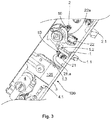
- FIG. 3 shows an inventive system 100 for a lock 101, eg. For a self-locking panic lock 101.
- the actuator 10 for detecting the position of at least one auxiliary latch 1.1 and a case 2.1 is used.
- the system 100 has a stationary component 3, for example in the form of a cuff 3, with respect to which the position detection of the auxiliary latch 1.1 and the latch 2.1 takes place.
- a stationary component 3 can also be understood any fixed part of the panic lock 101, such as. B. a housing or a housing part.
- For position detection microswitch 21, 22 are used.
- the microswitches 21, 22 each have a switching lug 21a, 22a, which is actuated by the contact element 12 when the actuating element 10 passes by.
- the first actuating element 10 according to the invention is attached to the movable component 1 of the auxiliary latch 1.1, which is moved linearly.
- the second actuating element 10 according to the invention is fastened to a rotatable nut 2.
- the panic lock 101 on a lock cylinder 4 wherein it is also conceivable that for detecting the position of the lock cylinder 4, a third inventive actuator 10 may be provided.
- the panic lock 101 is shown in a state in which the panic lock 101 is unlocked, a latch 4.1 is retracted into a lock housing behind the forend 3, a corresponding door, not shown, is open and the nut 2 is in an actuated or tightened position located.
- FIGS. 4a and 4b show in an enlarged view the area of the FIG. 3 around the first movable component 1, which is connected to the auxiliary latch 1.1, respectively from above and from below.
- a plateau 1.3 is provided on the first movable component 1, which is fastened to the movable component 1 with the aid of a bolt 1.2.
- the plateau 1.3 moves with the movable component 1.
- a threaded receptacle 1a for the threaded body 11 of the first actuating element 10 is provided in the plateau 1.3.
- the first Microswitch 21 is attached by means of the contacts 21.1, 21.2, 21.3 to a circuit board, not shown.
- the extended position of the auxiliary latch 1.1 is detected, wherein the terminal contact element 12 rests against the switching lug 21a and thus actuates the first microswitch 21.
- the auxiliary latch 1.1 is pushed through the door frame back into the lock housing behind the forend 3.
- the actuating element 10 moves back with the first movable member 1 and releases the switching lug 21 a of the switch 21.
- the switch 21 is thus opened, whereby a retracted position of the auxiliary latch 1.1 can be detected.
- the auxiliary latch 1.1 moves again from a corresponding opening in the forend 3 from the lock housing. In this position, the switch 21 is operated again.
- FIGS. 5a and 5b show in an enlarged view the area of the FIG. 3 about the second movable member 2 in the form of a nut 2 respectively from above and from below.
- a threaded receptacle 2a for the threaded body 11 of the second actuating element 10 is provided in the nut 2.
- the second micro-switch 22 is attached by means of the contacts 22.1, 22.2, 22.3 to a circuit board, not shown.
- the nut 2 is in the shown state of the panic lock 101, in which the panic lock 101 is unlocked, tightened. In this case, the terminal contact element 12 is spaced from the switching lug 22a, whereby the second microswitch 22 is opened.
- the nut 2 is pivoted clockwise, whereby the contact element 12 again comes into the switching area x on the switching flag 22a to actuate the second microswitch 22.
- a rest position of the nut 2 can be detected.
- FIG. 5c essentially shows the area from the FIG. 5a , wherein the actuating element 10 according to the invention is taken from the threaded receptacle 2a on the nut 2.
- the actuating element 10 has a threaded body 11 with a developed transverse web 13 and a subsequent, extending through the threaded body 11 and from the Has threaded body 11 extending contact element 12.
- the web 13 is located between the threaded body 11 and the contact element 12.
- the contact element 12 may have a longer actuating arm.
- the transverse web 13 and the contact element 12 can be unwound at different ends of the threaded body 11, as for example. In the FIG. 1 is shown.
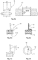
- FIG. 6a shows again in detail how an inner bias voltage V in the threaded body 11 can be adjusted, namely by an excess of the outer diameter d2 of the threaded body 11 with respect to the inner diameter d1 in the grooves in the threaded receptacle 1a, 2a on the movable member 1, 2, or by a deviation of the slope d2 between the turns of the threaded body 11 from the slope d1 of the turns in the threaded receptacle 1a, 2a.
- the self-locking of the actuating element 10 can be realized in the set position.
- the threaded body 11 may have a surface structure 11.1 to secure the threaded body 11 on the movable member 1, 2 by static friction in the attached state. It is conceivable that the surface structure 11.1 may be formed as a roughened and / or textured surface on the threaded body 11.
- the actuating element 10 can be formed from an electrically conductive material, for example to enable an electrical connection between the switch 21, 22 and the movable component 1, 2. It is conceivable that the actuating element 10 may have an electrically insulating sheath 15, as in the FIG. 6c is shown. The electrically insulating sheath 15 can prevent unwanted power transmission from the actuating element 10. Alternatively, however, it is also conceivable that the actuating element 10 may be formed of a non-conductive material.
- an optical and / or magnetic sensor element 14 for interacting with an optical and / or magnetic sensor can be attached to the contact element 12 as an alternative switch 21, 22.
- the actuating element 10 may be formed of a hollow wire, wherein in the actuating element 10, a tubular channel 16 may be formed in order to transfer liquid and / or gaseous media between two components can.
- the invention is not limited in its execution to the embodiments of the invention described above. Rather, a plurality of variants is conceivable, in which form and from which materials the actuating element 10 can be formed.
- Conceivable are materials such as a temperature-dependent shape memory material and / or a thermally conductive material, etc.
- the actuator 10 can be used in all mechatronic, optical and / or magnetic systems with movable components for their position detection.
Landscapes
- Engineering & Computer Science (AREA)
- Computer Security & Cryptography (AREA)
- Structural Engineering (AREA)
- Push-Button Switches (AREA)
Priority Applications (2)
| Application Number | Priority Date | Filing Date | Title |
|---|---|---|---|
| EP17162441.4A EP3379552B1 (fr) | 2017-03-22 | 2017-03-22 | Élément d'actionnement destiné au déplacement d'un élément de construction mobile |
| DK17162441.4T DK3379552T3 (da) | 2017-03-22 | 2017-03-22 | Betjeningselement til betjening af et bevægeligt komponentelement |
Applications Claiming Priority (1)
| Application Number | Priority Date | Filing Date | Title |
|---|---|---|---|
| EP17162441.4A EP3379552B1 (fr) | 2017-03-22 | 2017-03-22 | Élément d'actionnement destiné au déplacement d'un élément de construction mobile |
Publications (2)
| Publication Number | Publication Date |
|---|---|
| EP3379552A1 true EP3379552A1 (fr) | 2018-09-26 |
| EP3379552B1 EP3379552B1 (fr) | 2020-02-12 |
Family
ID=58401511
Family Applications (1)
| Application Number | Title | Priority Date | Filing Date |
|---|---|---|---|
| EP17162441.4A Active EP3379552B1 (fr) | 2017-03-22 | 2017-03-22 | Élément d'actionnement destiné au déplacement d'un élément de construction mobile |
Country Status (2)
| Country | Link |
|---|---|
| EP (1) | EP3379552B1 (fr) |
| DK (1) | DK3379552T3 (fr) |
Citations (5)
| Publication number | Priority date | Publication date | Assignee | Title |
|---|---|---|---|---|
| US3715530A (en) * | 1971-08-24 | 1973-02-06 | Westran Corp | Actuating device |
| DE2815888A1 (de) * | 1977-08-30 | 1979-02-15 | Saginomiya Seisakusho Inc | Druckabhaengiger schalter |
| GB2225375A (en) * | 1988-11-25 | 1990-05-30 | Waertsilae Oy Ab | Electromechanical door lock |
| DE29503880U1 (de) * | 1995-03-07 | 1995-05-11 | Theodor Kromer GmbH & Co KG Spezialfabrik für Sicherheitsschlösser, 79224 Umkirch | Permutationsschloß mit einer Nockenscheibe und mehreren Zuhaltungsscheiben |
| WO1999007967A1 (fr) * | 1997-08-05 | 1999-02-18 | Atoma International Inc. | Porte ressort bidirectionnel pour actionneur |
-
2017
- 2017-03-22 EP EP17162441.4A patent/EP3379552B1/fr active Active
- 2017-03-22 DK DK17162441.4T patent/DK3379552T3/da active
Patent Citations (5)
| Publication number | Priority date | Publication date | Assignee | Title |
|---|---|---|---|---|
| US3715530A (en) * | 1971-08-24 | 1973-02-06 | Westran Corp | Actuating device |
| DE2815888A1 (de) * | 1977-08-30 | 1979-02-15 | Saginomiya Seisakusho Inc | Druckabhaengiger schalter |
| GB2225375A (en) * | 1988-11-25 | 1990-05-30 | Waertsilae Oy Ab | Electromechanical door lock |
| DE29503880U1 (de) * | 1995-03-07 | 1995-05-11 | Theodor Kromer GmbH & Co KG Spezialfabrik für Sicherheitsschlösser, 79224 Umkirch | Permutationsschloß mit einer Nockenscheibe und mehreren Zuhaltungsscheiben |
| WO1999007967A1 (fr) * | 1997-08-05 | 1999-02-18 | Atoma International Inc. | Porte ressort bidirectionnel pour actionneur |
Also Published As
| Publication number | Publication date |
|---|---|
| DK3379552T3 (da) | 2020-03-30 |
| EP3379552B1 (fr) | 2020-02-12 |
Similar Documents
| Publication | Publication Date | Title |
|---|---|---|
| EP2395605B1 (fr) | Elément de serrage de ressort et bornier | |
| EP1636454B1 (fr) | Barillet electromagnetique | |
| EP0646688A1 (fr) | Poignée extérieure pour une porte spécialement pour porte de véhicule automobile | |
| EP1493888A1 (fr) | Serrure de porte de véhicule automobile | |
| DE102018126469B3 (de) | Federanschlusseinrichtung zum Anschließen eines elektrischen Leiters | |
| WO2020074032A1 (fr) | Serrure de véhicule automobile | |
| EP3474303B1 (fr) | Actionneur | |
| EP3819449A1 (fr) | Serrure de véhicule automobile | |
| EP1997986B1 (fr) | Serrure, en particulier serrure anti-panique dotée d'un capteur de position à actionnement au pied | |
| EP3379552B1 (fr) | Élément d'actionnement destiné au déplacement d'un élément de construction mobile | |
| EP2933404A1 (fr) | Ouverture de porte comprenant un contact de retour d'information | |
| EP1024238A2 (fr) | Dispositif pour la détection de la position d'un pêne de serrure | |
| DE102017106223A1 (de) | Betätigungselement für einen Schalter | |
| DE19902919A1 (de) | Vorrichtung zum Schalten einer elektrischen Verbindung, insbesondere Scharnierschalter | |
| DE102012108991B4 (de) | Schaltkontakt | |
| WO2012130204A1 (fr) | Dispositif de verrouillage pour un dispositif de charge d'un véhicule à moteur | |
| DE10329636B4 (de) | Elektrisch betätigbarer Türöffner | |
| DE4405383A1 (de) | Außengriffanordnung für eine Tür, insbesondere eine Kraftfahrzeugtür | |
| DE2458652A1 (de) | Zylinderschlossanordnung mit alarmeinrichtung | |
| DE19902910C2 (de) | Vorrichtung zum Schalten einer elektrischen Verbindung, insbesondere Schwenkhebelschalter | |
| DE102005014701A1 (de) | Verriegelungsanlage für ein bewegliches Schliesselement | |
| EP2980338B1 (fr) | Systeme de cylindre de serrure | |
| DE102022107120B4 (de) | Elektrische Verbindungsvorrichtung | |
| DE7438635U (de) | Vorrichtung zur elektrischen Überwachung der Verriegelung eines Schlosses | |
| DE4207128A1 (de) | Kontaktvorrichtung zur elektrischen ueberwachung von eingangstueren |
Legal Events
| Date | Code | Title | Description |
|---|---|---|---|
| PUAI | Public reference made under article 153(3) epc to a published international application that has entered the european phase |
Free format text: ORIGINAL CODE: 0009012 |
|
| STAA | Information on the status of an ep patent application or granted ep patent |
Free format text: STATUS: THE APPLICATION HAS BEEN PUBLISHED |
|
| AK | Designated contracting states |
Kind code of ref document: A1 Designated state(s): AL AT BE BG CH CY CZ DE DK EE ES FI FR GB GR HR HU IE IS IT LI LT LU LV MC MK MT NL NO PL PT RO RS SE SI SK SM TR |
|
| AX | Request for extension of the european patent |
Extension state: BA ME |
|
| STAA | Information on the status of an ep patent application or granted ep patent |
Free format text: STATUS: REQUEST FOR EXAMINATION WAS MADE |
|
| 17P | Request for examination filed |
Effective date: 20190326 |
|
| RBV | Designated contracting states (corrected) |
Designated state(s): AL AT BE BG CH CY CZ DE DK EE ES FI FR GB GR HR HU IE IS IT LI LT LU LV MC MK MT NL NO PL PT RO RS SE SI SK SM TR |
|
| GRAP | Despatch of communication of intention to grant a patent |
Free format text: ORIGINAL CODE: EPIDOSNIGR1 |
|
| STAA | Information on the status of an ep patent application or granted ep patent |
Free format text: STATUS: GRANT OF PATENT IS INTENDED |
|
| RIC1 | Information provided on ipc code assigned before grant |
Ipc: E05B 15/04 20060101ALI20190807BHEP Ipc: E05B 17/22 20060101ALI20190807BHEP Ipc: H01H 3/16 20060101ALI20190807BHEP Ipc: H01H 3/42 20060101AFI20190807BHEP Ipc: H01H 3/30 20060101ALI20190807BHEP Ipc: E05B 63/20 20060101ALN20190807BHEP Ipc: H01H 13/18 20060101ALI20190807BHEP Ipc: E05B 63/00 20060101ALI20190807BHEP |
|
| INTG | Intention to grant announced |
Effective date: 20190830 |
|
| GRAS | Grant fee paid |
Free format text: ORIGINAL CODE: EPIDOSNIGR3 |
|
| GRAA | (expected) grant |
Free format text: ORIGINAL CODE: 0009210 |
|
| STAA | Information on the status of an ep patent application or granted ep patent |
Free format text: STATUS: THE PATENT HAS BEEN GRANTED |
|
| AK | Designated contracting states |
Kind code of ref document: B1 Designated state(s): AL AT BE BG CH CY CZ DE DK EE ES FI FR GB GR HR HU IE IS IT LI LT LU LV MC MK MT NL NO PL PT RO RS SE SI SK SM TR |
|
| REG | Reference to a national code |
Ref country code: GB Ref legal event code: FG4D Free format text: NOT ENGLISH |
|
| REG | Reference to a national code |
Ref country code: CH Ref legal event code: EP |
|
| REG | Reference to a national code |
Ref country code: AT Ref legal event code: REF Ref document number: 1233203 Country of ref document: AT Kind code of ref document: T Effective date: 20200215 |
|
| REG | Reference to a national code |
Ref country code: CH Ref legal event code: NV Representative=s name: FREI PATENTANWALTSBUERO AG, CH |
|
| REG | Reference to a national code |
Ref country code: IE Ref legal event code: FG4D Free format text: LANGUAGE OF EP DOCUMENT: GERMAN |
|
| REG | Reference to a national code |
Ref country code: DE Ref legal event code: R096 Ref document number: 502017003723 Country of ref document: DE |
|
| REG | Reference to a national code |
Ref country code: DK Ref legal event code: T3 Effective date: 20200325 |
|
| REG | Reference to a national code |
Ref country code: FI Ref legal event code: FGE |
|
| REG | Reference to a national code |
Ref country code: SE Ref legal event code: TRGR |
|
| REG | Reference to a national code |
Ref country code: NO Ref legal event code: T2 Effective date: 20200212 |
|
| PG25 | Lapsed in a contracting state [announced via postgrant information from national office to epo] |
Ref country code: RS Free format text: LAPSE BECAUSE OF FAILURE TO SUBMIT A TRANSLATION OF THE DESCRIPTION OR TO PAY THE FEE WITHIN THE PRESCRIBED TIME-LIMIT Effective date: 20200212 |
|
| REG | Reference to a national code |
Ref country code: LT Ref legal event code: MG4D |
|
| REG | Reference to a national code |
Ref country code: NL Ref legal event code: MP Effective date: 20200212 |
|
| PG25 | Lapsed in a contracting state [announced via postgrant information from national office to epo] |
Ref country code: IS Free format text: LAPSE BECAUSE OF FAILURE TO SUBMIT A TRANSLATION OF THE DESCRIPTION OR TO PAY THE FEE WITHIN THE PRESCRIBED TIME-LIMIT Effective date: 20200612 Ref country code: BG Free format text: LAPSE BECAUSE OF FAILURE TO SUBMIT A TRANSLATION OF THE DESCRIPTION OR TO PAY THE FEE WITHIN THE PRESCRIBED TIME-LIMIT Effective date: 20200512 Ref country code: LV Free format text: LAPSE BECAUSE OF FAILURE TO SUBMIT A TRANSLATION OF THE DESCRIPTION OR TO PAY THE FEE WITHIN THE PRESCRIBED TIME-LIMIT Effective date: 20200212 Ref country code: GR Free format text: LAPSE BECAUSE OF FAILURE TO SUBMIT A TRANSLATION OF THE DESCRIPTION OR TO PAY THE FEE WITHIN THE PRESCRIBED TIME-LIMIT Effective date: 20200513 Ref country code: HR Free format text: LAPSE BECAUSE OF FAILURE TO SUBMIT A TRANSLATION OF THE DESCRIPTION OR TO PAY THE FEE WITHIN THE PRESCRIBED TIME-LIMIT Effective date: 20200212 |
|
| PG25 | Lapsed in a contracting state [announced via postgrant information from national office to epo] |
Ref country code: NL Free format text: LAPSE BECAUSE OF FAILURE TO SUBMIT A TRANSLATION OF THE DESCRIPTION OR TO PAY THE FEE WITHIN THE PRESCRIBED TIME-LIMIT Effective date: 20200212 |
|
| PG25 | Lapsed in a contracting state [announced via postgrant information from national office to epo] |
Ref country code: ES Free format text: LAPSE BECAUSE OF FAILURE TO SUBMIT A TRANSLATION OF THE DESCRIPTION OR TO PAY THE FEE WITHIN THE PRESCRIBED TIME-LIMIT Effective date: 20200212 Ref country code: SK Free format text: LAPSE BECAUSE OF FAILURE TO SUBMIT A TRANSLATION OF THE DESCRIPTION OR TO PAY THE FEE WITHIN THE PRESCRIBED TIME-LIMIT Effective date: 20200212 Ref country code: SM Free format text: LAPSE BECAUSE OF FAILURE TO SUBMIT A TRANSLATION OF THE DESCRIPTION OR TO PAY THE FEE WITHIN THE PRESCRIBED TIME-LIMIT Effective date: 20200212 Ref country code: EE Free format text: LAPSE BECAUSE OF FAILURE TO SUBMIT A TRANSLATION OF THE DESCRIPTION OR TO PAY THE FEE WITHIN THE PRESCRIBED TIME-LIMIT Effective date: 20200212 Ref country code: RO Free format text: LAPSE BECAUSE OF FAILURE TO SUBMIT A TRANSLATION OF THE DESCRIPTION OR TO PAY THE FEE WITHIN THE PRESCRIBED TIME-LIMIT Effective date: 20200212 Ref country code: PT Free format text: LAPSE BECAUSE OF FAILURE TO SUBMIT A TRANSLATION OF THE DESCRIPTION OR TO PAY THE FEE WITHIN THE PRESCRIBED TIME-LIMIT Effective date: 20200705 Ref country code: CZ Free format text: LAPSE BECAUSE OF FAILURE TO SUBMIT A TRANSLATION OF THE DESCRIPTION OR TO PAY THE FEE WITHIN THE PRESCRIBED TIME-LIMIT Effective date: 20200212 Ref country code: LT Free format text: LAPSE BECAUSE OF FAILURE TO SUBMIT A TRANSLATION OF THE DESCRIPTION OR TO PAY THE FEE WITHIN THE PRESCRIBED TIME-LIMIT Effective date: 20200212 |
|
| REG | Reference to a national code |
Ref country code: DE Ref legal event code: R097 Ref document number: 502017003723 Country of ref document: DE |
|
| PG25 | Lapsed in a contracting state [announced via postgrant information from national office to epo] |
Ref country code: MC Free format text: LAPSE BECAUSE OF FAILURE TO SUBMIT A TRANSLATION OF THE DESCRIPTION OR TO PAY THE FEE WITHIN THE PRESCRIBED TIME-LIMIT Effective date: 20200212 |
|
| PLBE | No opposition filed within time limit |
Free format text: ORIGINAL CODE: 0009261 |
|
| STAA | Information on the status of an ep patent application or granted ep patent |
Free format text: STATUS: NO OPPOSITION FILED WITHIN TIME LIMIT |
|
| REG | Reference to a national code |
Ref country code: BE Ref legal event code: MM Effective date: 20200331 |
|
| PG25 | Lapsed in a contracting state [announced via postgrant information from national office to epo] |
Ref country code: LU Free format text: LAPSE BECAUSE OF NON-PAYMENT OF DUE FEES Effective date: 20200322 |
|
| 26N | No opposition filed |
Effective date: 20201113 |
|
| PG25 | Lapsed in a contracting state [announced via postgrant information from national office to epo] |
Ref country code: IT Free format text: LAPSE BECAUSE OF FAILURE TO SUBMIT A TRANSLATION OF THE DESCRIPTION OR TO PAY THE FEE WITHIN THE PRESCRIBED TIME-LIMIT Effective date: 20200212 Ref country code: FR Free format text: LAPSE BECAUSE OF NON-PAYMENT OF DUE FEES Effective date: 20200412 Ref country code: IE Free format text: LAPSE BECAUSE OF NON-PAYMENT OF DUE FEES Effective date: 20200322 |
|
| PG25 | Lapsed in a contracting state [announced via postgrant information from national office to epo] |
Ref country code: SI Free format text: LAPSE BECAUSE OF FAILURE TO SUBMIT A TRANSLATION OF THE DESCRIPTION OR TO PAY THE FEE WITHIN THE PRESCRIBED TIME-LIMIT Effective date: 20200212 Ref country code: PL Free format text: LAPSE BECAUSE OF FAILURE TO SUBMIT A TRANSLATION OF THE DESCRIPTION OR TO PAY THE FEE WITHIN THE PRESCRIBED TIME-LIMIT Effective date: 20200212 Ref country code: BE Free format text: LAPSE BECAUSE OF NON-PAYMENT OF DUE FEES Effective date: 20200331 |
|
| GBPC | Gb: european patent ceased through non-payment of renewal fee |
Effective date: 20210322 |
|
| PG25 | Lapsed in a contracting state [announced via postgrant information from national office to epo] |
Ref country code: GB Free format text: LAPSE BECAUSE OF NON-PAYMENT OF DUE FEES Effective date: 20210322 |
|
| PG25 | Lapsed in a contracting state [announced via postgrant information from national office to epo] |
Ref country code: TR Free format text: LAPSE BECAUSE OF FAILURE TO SUBMIT A TRANSLATION OF THE DESCRIPTION OR TO PAY THE FEE WITHIN THE PRESCRIBED TIME-LIMIT Effective date: 20200212 Ref country code: MT Free format text: LAPSE BECAUSE OF FAILURE TO SUBMIT A TRANSLATION OF THE DESCRIPTION OR TO PAY THE FEE WITHIN THE PRESCRIBED TIME-LIMIT Effective date: 20200212 Ref country code: CY Free format text: LAPSE BECAUSE OF FAILURE TO SUBMIT A TRANSLATION OF THE DESCRIPTION OR TO PAY THE FEE WITHIN THE PRESCRIBED TIME-LIMIT Effective date: 20200212 |
|
| PG25 | Lapsed in a contracting state [announced via postgrant information from national office to epo] |
Ref country code: MK Free format text: LAPSE BECAUSE OF FAILURE TO SUBMIT A TRANSLATION OF THE DESCRIPTION OR TO PAY THE FEE WITHIN THE PRESCRIBED TIME-LIMIT Effective date: 20200212 Ref country code: AL Free format text: LAPSE BECAUSE OF FAILURE TO SUBMIT A TRANSLATION OF THE DESCRIPTION OR TO PAY THE FEE WITHIN THE PRESCRIBED TIME-LIMIT Effective date: 20200212 |
|
| REG | Reference to a national code |
Ref country code: AT Ref legal event code: MM01 Ref document number: 1233203 Country of ref document: AT Kind code of ref document: T Effective date: 20220322 |
|
| PG25 | Lapsed in a contracting state [announced via postgrant information from national office to epo] |
Ref country code: AT Free format text: LAPSE BECAUSE OF NON-PAYMENT OF DUE FEES Effective date: 20220322 |
|
| PGFP | Annual fee paid to national office [announced via postgrant information from national office to epo] |
Ref country code: CH Payment date: 20250401 Year of fee payment: 9 |
|
| REG | Reference to a national code |
Ref country code: CH Ref legal event code: U11 Free format text: ST27 STATUS EVENT CODE: U-0-0-U10-U11 (AS PROVIDED BY THE NATIONAL OFFICE) Effective date: 20260401 |
|
| PGFP | Annual fee paid to national office [announced via postgrant information from national office to epo] |
Ref country code: SE Payment date: 20260319 Year of fee payment: 10 |
|
| PGFP | Annual fee paid to national office [announced via postgrant information from national office to epo] |
Ref country code: DE Payment date: 20260319 Year of fee payment: 10 Ref country code: NO Payment date: 20260323 Year of fee payment: 10 Ref country code: DK Payment date: 20260324 Year of fee payment: 10 |
|
| PGFP | Annual fee paid to national office [announced via postgrant information from national office to epo] |
Ref country code: FI Payment date: 20260323 Year of fee payment: 10 |