EP3379627B1 - Gasdiffusionsschicht für eine brennstoffzelle, verfahren zur herstellung der besagten schicht, membranelektrodenbaugruppe und brennstoffzelle - Google Patents
Gasdiffusionsschicht für eine brennstoffzelle, verfahren zur herstellung der besagten schicht, membranelektrodenbaugruppe und brennstoffzelle Download PDFInfo
- Publication number
- EP3379627B1 EP3379627B1 EP16865905.0A EP16865905A EP3379627B1 EP 3379627 B1 EP3379627 B1 EP 3379627B1 EP 16865905 A EP16865905 A EP 16865905A EP 3379627 B1 EP3379627 B1 EP 3379627B1
- Authority
- EP
- European Patent Office
- Prior art keywords
- gas
- diffusion layer
- hollows
- fluid flow
- diffusion
- Prior art date
- Legal status (The legal status is an assumption and is not a legal conclusion. Google has not performed a legal analysis and makes no representation as to the accuracy of the status listed.)
- Active
Links
Images




Classifications
-
- H—ELECTRICITY
- H01—ELECTRIC ELEMENTS
- H01M—PROCESSES OR MEANS, e.g. BATTERIES, FOR THE DIRECT CONVERSION OF CHEMICAL ENERGY INTO ELECTRICAL ENERGY
- H01M4/00—Electrodes
- H01M4/86—Inert electrodes with catalytic activity, e.g. for fuel cells
- H01M4/8605—Porous electrodes
- H01M4/8626—Porous electrodes characterised by the form
-
- H—ELECTRICITY
- H01—ELECTRIC ELEMENTS
- H01M—PROCESSES OR MEANS, e.g. BATTERIES, FOR THE DIRECT CONVERSION OF CHEMICAL ENERGY INTO ELECTRICAL ENERGY
- H01M8/00—Fuel cells; Manufacture thereof
- H01M8/02—Details
- H01M8/0202—Collectors; Separators, e.g. bipolar separators; Interconnectors
- H01M8/023—Porous and characterised by the material
- H01M8/0241—Composites
- H01M8/0243—Composites in the form of mixtures
-
- H—ELECTRICITY
- H01—ELECTRIC ELEMENTS
- H01M—PROCESSES OR MEANS, e.g. BATTERIES, FOR THE DIRECT CONVERSION OF CHEMICAL ENERGY INTO ELECTRICAL ENERGY
- H01M4/00—Electrodes
- H01M4/86—Inert electrodes with catalytic activity, e.g. for fuel cells
- H01M4/88—Processes of manufacture
-
- H—ELECTRICITY
- H01—ELECTRIC ELEMENTS
- H01M—PROCESSES OR MEANS, e.g. BATTERIES, FOR THE DIRECT CONVERSION OF CHEMICAL ENERGY INTO ELECTRICAL ENERGY
- H01M4/00—Electrodes
- H01M4/86—Inert electrodes with catalytic activity, e.g. for fuel cells
- H01M4/88—Processes of manufacture
- H01M4/8803—Supports for the deposition of the catalytic active composition
- H01M4/8807—Gas diffusion layers
-
- H—ELECTRICITY
- H01—ELECTRIC ELEMENTS
- H01M—PROCESSES OR MEANS, e.g. BATTERIES, FOR THE DIRECT CONVERSION OF CHEMICAL ENERGY INTO ELECTRICAL ENERGY
- H01M4/00—Electrodes
- H01M4/86—Inert electrodes with catalytic activity, e.g. for fuel cells
- H01M4/96—Carbon-based electrodes
-
- H—ELECTRICITY
- H01—ELECTRIC ELEMENTS
- H01M—PROCESSES OR MEANS, e.g. BATTERIES, FOR THE DIRECT CONVERSION OF CHEMICAL ENERGY INTO ELECTRICAL ENERGY
- H01M8/00—Fuel cells; Manufacture thereof
- H01M8/02—Details
-
- H—ELECTRICITY
- H01—ELECTRIC ELEMENTS
- H01M—PROCESSES OR MEANS, e.g. BATTERIES, FOR THE DIRECT CONVERSION OF CHEMICAL ENERGY INTO ELECTRICAL ENERGY
- H01M8/00—Fuel cells; Manufacture thereof
- H01M8/02—Details
- H01M8/0202—Collectors; Separators, e.g. bipolar separators; Interconnectors
- H01M8/023—Porous and characterised by the material
- H01M8/0234—Carbonaceous material
-
- H—ELECTRICITY
- H01—ELECTRIC ELEMENTS
- H01M—PROCESSES OR MEANS, e.g. BATTERIES, FOR THE DIRECT CONVERSION OF CHEMICAL ENERGY INTO ELECTRICAL ENERGY
- H01M8/00—Fuel cells; Manufacture thereof
- H01M8/02—Details
- H01M8/0202—Collectors; Separators, e.g. bipolar separators; Interconnectors
- H01M8/023—Porous and characterised by the material
- H01M8/0239—Organic resins; Organic polymers
-
- H—ELECTRICITY
- H01—ELECTRIC ELEMENTS
- H01M—PROCESSES OR MEANS, e.g. BATTERIES, FOR THE DIRECT CONVERSION OF CHEMICAL ENERGY INTO ELECTRICAL ENERGY
- H01M8/00—Fuel cells; Manufacture thereof
- H01M8/10—Fuel cells with solid electrolytes
-
- Y—GENERAL TAGGING OF NEW TECHNOLOGICAL DEVELOPMENTS; GENERAL TAGGING OF CROSS-SECTIONAL TECHNOLOGIES SPANNING OVER SEVERAL SECTIONS OF THE IPC; TECHNICAL SUBJECTS COVERED BY FORMER USPC CROSS-REFERENCE ART COLLECTIONS [XRACs] AND DIGESTS
- Y02—TECHNOLOGIES OR APPLICATIONS FOR MITIGATION OR ADAPTATION AGAINST CLIMATE CHANGE
- Y02E—REDUCTION OF GREENHOUSE GAS [GHG] EMISSIONS, RELATED TO ENERGY GENERATION, TRANSMISSION OR DISTRIBUTION
- Y02E60/00—Enabling technologies; Technologies with a potential or indirect contribution to GHG emissions mitigation
- Y02E60/30—Hydrogen technology
- Y02E60/50—Fuel cells
-
- Y—GENERAL TAGGING OF NEW TECHNOLOGICAL DEVELOPMENTS; GENERAL TAGGING OF CROSS-SECTIONAL TECHNOLOGIES SPANNING OVER SEVERAL SECTIONS OF THE IPC; TECHNICAL SUBJECTS COVERED BY FORMER USPC CROSS-REFERENCE ART COLLECTIONS [XRACs] AND DIGESTS
- Y02—TECHNOLOGIES OR APPLICATIONS FOR MITIGATION OR ADAPTATION AGAINST CLIMATE CHANGE
- Y02P—CLIMATE CHANGE MITIGATION TECHNOLOGIES IN THE PRODUCTION OR PROCESSING OF GOODS
- Y02P70/00—Climate change mitigation technologies in the production process for final industrial or consumer products
- Y02P70/50—Manufacturing or production processes characterised by the final manufactured product
Definitions
- the technical field relates to fuel cells, particularly, membrane-electrode assemblies used for fuel cells, gas-diffusion layers provided in the membrane-electrode assemblies, and processes for producing the same.
- fuel cells e.g., polymer electrolyte fuel cells
- one side of an electrolyte membrane is exposed to a fuel gas such as hydrogen, and another side thereof is exposed to an oxygen gas.
- polymer electrolyte fuel cells are based on electrical extraction of reaction energies produced in this way.
- MEAs membrane-electrode assemblies
- MEAs each include : hydrogen-ion-conductive polymer electrolyte membranes; pairs of electrode layers that each hold the polymer electrolyte membranes; catalyst layers; and gas-diffusion layers.
- Catalyst layers contain carbon powders carrying platinum-group catalysts as main ingredients and are formed on both sides of the polymer electrolyte membranes.
- the gas-diffusion layers are formed on the catalyst layers and combine power-collection actions, gas permeability, and water repellency.
- the gas-diffusion layers have sufficient gas permeability and gas-diffusion properties, such that the gas-diffusion layers uniformly supply gases coming from the separators to the catalyst layers.
- the gas-diffusion layers have excellent electric conductance so as to serve as electron-conducting pathways between the gas-diffusion layers and the catalyst layers.
- electrically-conductive porous substrates such as carbon-fiber unwoven fabrics, and carbon-fiber woven fabrics have been employed for the gas-diffusion layers.
- the gas-diffusion layers have high water repellency, so as to remove excess water produced through battery reactions in the catalyst layers from the MEA systems, thereby preventing the produced water from blocking pores of the gas-diffusion layers.
- water-repellant layers that contain as main ingredients carbon powders, and water-repellant resins such as fluorine resins, are frequently provided at sides adjacent to the catalyst layers, which are made of electrically-conductive porous substrates.
- the water-repellant layers have higher water repellency than the electrically-conductive porous substrates, it becomes possible to quickly discharge the excess water produced in the catalyst layers to the outside of the MEA systems.
- JP-A-2003-197202 discloses gas-diffusion layers in which water-repellant layers are formed on electrically-conductive porous substrates.
- water-repellant layers that includes carbon materials (e.g., carbon black, hollow carbon fibers) and fluorine resins are formed on surfaces of carbon-fiber based substrate 'e.g., papers, woven fabrics, unwoven fabrics).
- carbon materials e.g., carbon black, hollow carbon fibers
- fluorine resins are formed on surfaces of carbon-fiber based substrate 'e.g., papers, woven fabrics, unwoven fabrics.
- WO2010/050219 JP-A-2003-187809 , and JP-A-2007-141783 each disclose gas-diffusion layers in which no carbon fibers are used as substrates.
- the gas-diffusion layers disclosed in WO2010/050219 are formed of porous materials that include as main ingredients electrically-conductive particles, and polymer resins, and further includes smaller amounts of carbon fibers compared with the amounts of polymer resins.
- the gas-diffusion layers disclosed in JP-A-2003-187809 are formed by mixing graphite, carbon black, unbaked PTFE and baked PTFE.
- the gas-diffusion layers disclosed in JP-A-2007-141783 are formed of boron-modified carbon, carbon fibers, and fluorine resins.
- Japanese patent No. 5,099,017 discloses gas-diffusion layers that are formed of porous materials.
- the porous materials are produced through foam molding of foamable slurries containing starting material powders of corrosion-resistant metals, foaming agents, and binders, and thus, have three-dimensional network structures in which hollows communicating with each other are present.
- Japanese patent No. 5,476,694 discloses gas-diffusion layers that are made of water-repellant porous materials having recessed parts and projecting parts. The most frequently distributed diameters of hollows present in the projecting parts are larger than those of hollows present in the recessed parts in the porous materials.
- JP-A-2005-267902 and JP-A-2011-243314 disclose gas-diffusion layers having pore diameters set to predetermined ranges.
- a diameter of pores having a high-frequency peak of pore volume is adjusted to a range from 10 ⁇ m to 30 ⁇ m.
- a mean pore diameter is adjusted to a range from 31 ⁇ m to 49 ⁇ m.
- US 2014/272659 A discloses a microporous layer (MPL) forming a portion of a gas diffusion layer assembly positioned adjacent to a catalyst layer, said MPL comprising a first carbon-based material layer comprising a plurality of hydrophobic pores having a diameter of 0.05 to 0.2 ⁇ m and a plurality of bores with a diameter of 1 to 20 ⁇ m, and a second carbon-based material layer configured to be disposed between the catalyst layer and the first carbon-based layer.
- MPL microporous layer
- water-repellent layers are provided on surfaces of carbon fiber substrates in the gas-diffusion layers according to the method disclosed in JP-A-2003-197202 , such water-repellent layers become factors for increases in the electric resistance, and thus, IR loss will be caused during the power generation. Thus, the presence of water-repellent layers becomes a factor for deteriorations in the battery performance.
- the starting powdery material for the gas-diffusion layer which is made of a corrosion-resistant metal, has no gas permeability, and therefore, it would be required that the formed hollows communicate with each other.
- hollows produced through foam molding processes have larger mean diameters (e.g., 20-600 ⁇ m) .
- a mean diameter of pores is controlled to 10-50 ⁇ m by way of forming water-repellent layers on carbon fiber substrates in the gas-diffusion layers, in the same manner as JP-A-2003-197202 .
- a mean diameter of pores is considered 1 ⁇ m.
- the diameter of pores is larger, and therefore, the water-repellent layers cause increases in the electric resistance, and cause IR loss during power generation. That is, the presence of the water-repellent layers is a factor for deteriorations in the battery performance.
- an object of the present invention is to provide gas-diffusion layers for fuel cells that combine sufficient gas permeability/water-discharging properties, and higher conductivity, without substantially using any expensive carbon fiber substrates.
- the present invention makes it possible to solve the above-described problems.
- the present invention provides a gas-diffusion layer used for fuel cells comprising a porous material that includes as main ingredients : conductive particles, wherein the materials for conductive particles are carbon materials such as carbon black, graphite and activated carbon; and a polymer resin having water-repellency, wherein said gas-diffusion layer internally possesses pores with a size from 0.01 ⁇ m to 0.05 ⁇ m, and hollows with a size from about 1 ⁇ m to about 200 ⁇ m when determined by the method indicated in the description, wherein a ratio of areas of the hollows in a cross-section of the gas diffusion layer calculated as a ratio of the areas of the hollows to the total area of the cross-section is from 0.5% to 5% when determined by the method indicated in the description, and wherein a diameter of the hollow in a planar direction of the gas-diffusion layer is larger than a diameter of the hollows in a thickness direction of the gas-diffusion layer.
- the present invention provides a membrane-electrode assembly comprising the gas-diffusion layer according to the first aspect.
- the present invention provides a fuel cell comprising the gas-diffusion layer according to the first aspect.
- the present invention provides a method for producing a gas-diffusion layer used for fuel cells according to the first aspect, said method comprising: (i) kneading conductive particles selected from the group consisting of at least one of carbon black, graphite and activated carbon, a polymer resin having water repellency, a pore-forming agent, a surfactant, and a dispersion solvent into a mixture; (ii) rolling the mixture obtained in Step (i) to shape said mixture into a sheet; (iii) baking the sheet-shaped mixture to sublime the pore-forming agent, thereby forming hollows therein, and to remove the surfactant and the dispersion solvent; and (iv) further rolling the baked mixture to adjust a thickness of the baked mixture, wherein a diameter of the hollows in a planar direction in the sheet-shaped mixture in Step (iv) is larger than a diameter of the hollows in a thickness direction in said sheet-shaped mixture.
- pores with a size from 0.01 ⁇ m to 0.05 ⁇ m, and hollows with a size from about 1 ⁇ m to about 200 ⁇ m are formed inside porous material that includes as main ingredients conductive particles and polymer resins.
- the present invention makes it possible to significantly improve the gas permeability and the water-discharging properties, thereby improving power-generation performance of fuel cells.
- the present invention makes it possible to reduce costs and to simplify steps for production of fuel cells.
- the present invention provides a gas-diffusion layer used for fuel cells, including: a porous material that includes as main ingredients conductive particles and a polymer resin, wherein said gas-diffusion layer internally possesses pores with a size from 0.01 ⁇ m to 0.05 ⁇ m, and hollows with a size from about 1 ⁇ m to about 200 ⁇ m.
- porous material including as main ingredients conductive particles and polymer resins refers to a porous material that does not include any substrates made of carbon fibers, and that possesses a structure supported only by the conductive particles and the polymer resins.
- porous material is produced by using conductive particles and polymer resins
- surfactants and dispersion solvents are employed.
- the surfactants and the dispersion solvents are removed in the baking step. However, they may not sufficiently be removed, and, consequently, may remain in the porous material.
- porous material including as main ingredients conductive particles and polymer resins means that such remaining surfactants and dispersion solvents can be included in the porous material, as long as the porous material possesses a structure supported only by the conductive particles and the polymer resins.
- any materials e.g., carbon fibers
- the conductive particles e.g., carbon fibers
- the polymer resins e.g., polyethylene glycol dimethacrylate copolymer
- the surfactants and the dispersion solvents can also be included in the porous material.
- FIG. 1 A basic structure of a fuel cell according to the present embodiments will be described with reference to FIG. 1 .
- FIG. 1 is a schematic perspective view of a stack structure in polymer electrolyte fuel cell according to present embodiments.
- present embodiments are not limited to polymer electrolyte fuel cells, and thus, are applicable to various fuel cells.
- gas-non-permeable conductive materials such as copper and brass are employed.
- the current-collector plates 11 are provided with current-extraction terminal areas, and thus, currents are extracted therefrom during power generation.
- insulation plates 12 insulative resins such as fluorine resins and PPS resins are employed.
- edge plates 13 For the edge plates 13, highly rigid metal materials such as steel are employed.
- the edge plates 13 fasten and hold a stack of multiple battery cells 10, the current-collector plates 11, and the insulation plates 12, based on a pressure-applying unit not shown in the figures, at a predetermined load.
- the battery cell 10 will now be described based on FIG. 2 .
- FIG. 2 is a cross-section view of the battery cell 10.
- the battery cells 10 each have a structure in which an MEA 20 is placed between an anode-side separator 4a and a cathode-side separator 4b.
- separators 4 both the anode-side separator 4a and the cathode-side separator 4b may be referred to as separators 4 below.
- fluid flow channels 5 are formed. Fluid flow channels 5 for fuel gases are formed in the anode-side separator 4a, while fluid flow channels 5 for oxidant gases are formed in the cathode-side separator 4b.
- the fluid flow channels 5 are formed as grooves, and peripheral areas of the fluid flow channels 5 are configured as ribs 6.
- an anode catalyst layer 2a and a cathode catalyst layer 2b are formed on both sides of a polymer electrolyte membrane 1 that selectively transports hydrogen ions. Furthermore, an anode-side gas-diffusion layer 3a and a cathode-side gas-diffusion layer 3b are located on the external sides.
- perfluorocarbon sulfonic acid copolymers may be employed.
- materials used therefor are not particularly limited as long as they have proton conductance.
- layers including carbon materials carrying catalyst particles made of platinum or the like, and polymer electrolytes can be employed as the catalyst layers 2.
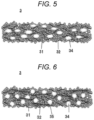
- FIGS. 3A and 3B it appears as if the succession of conductive particles 31 are interrupted by pores 33 and hollows 34. However, it is merely observed that the succession of conductive particles 31 are interrupted at certain spots.
- FIGS. 5, 6 , 9A, 9B , 11 , 12, 13 and 14 The same shall apply to FIGS. 5, 6 , 9A, 9B , 11 , 12, 13 and 14 .
- FIG. 3A is a view of an internal structure of the gas-diffusion layer 3 in an aspect not covered by claimed invention because the diameter of the hollows in a planar direction of the gas-diffusion layer is not represented larger than a diameter of the hollows in a thickness direction of the gas-diffusion layer.
- FIG. 3B is a view of an enlarged internal structure of gas-diffusion layer 3.
- the gas-diffusion layer 3 includes as main ingredients conductive particles 31 and polymer resins 32, and internally have pores 33 with a size of 0.01 ⁇ m to 0.05 ⁇ m, and hollows 34 of about 1 ⁇ m to about 200 ⁇ m.
- Materials for the conductive particles 31 are carbon materials such as carbon black, graphite, and activated carbon may be used.
- carbon black that has higher conductivity and larger pore volumes is preferably employed.
- acetylene black Ketchen black, furnace black, Vulcan, etc. can be used.
- a material that includes as a main ingredient acetylene black with few impurities, or acetylene black, and 5 wt% to 50 wt% of highly-conductive Ketchen black is preferably employed for the conductive particles 31.
- PTFE polytetrafluoroethylene
- FEP tetrafluoroetylene/hexafluoropropylene copolymers
- PVDF polyvinylidene difluoride
- ETFE ethylene/tetrafluoroethylene copolymers
- PCTFE polychlorotrifluoroethylene
- PFA polyfluoroethylene/perfluoroalkyl vinyl ether copolymers
- PTFE is preferably used for the polymer resins 32 since PTFE has favorable heat resistance, water repellency, and chemical resistance.
- a form of PTFE provided as a starting material may be a dispersion, powder, or the like.
- the form of dispersion is preferable since, needless to say, it realizes excellent dispersibility.
- the polymer resins 32 serves as binders that bind conductive particles 31 together.
- the polymer resins 32 have water repellency, they also play a role on preventing water from accumulating in the pores 33 and the hollows 34 inside the gas-diffusion layer 3, thus impeding the gas permeability.
- the gas-diffusion layer 3 internally have pores 33 with a size of 0.01 ⁇ m to 0.05 ⁇ m and hollows 34 with a size of about 1 ⁇ m to about 200 ⁇ m.
- the pores 33 with a size of 0.01 ⁇ m to 0.05 ⁇ m, are formed as gaps among the conductive particles 31.
- the pores 33 are formed as gaps among the primary particles of carbon black.
- a mean diameter of the primary particles of carbon black is about 0.02 ⁇ m to about 0.04 ⁇ m, the pores formed through filling of such carbon black will have a particles size from 0.01 ⁇ m to 0.05 ⁇ m.
- the gas-diffusion layer 3 may have inferior water discharging properties. Consequently, the gas-diffusion layer 3 may exhibit inferior water-discharging properties, and this may result in deteriorated battery performance due to the occurrence of flooding.
- the pores 33 are distributed throughout the entire internal body of gas-diffusion layer 3, and serve as pathways for diffusion of gases, or discharge of water/water vapor.
- a diameter of the pores can be measured based on the mercury intrusion technique.
- the hollows 34 with a size from about 1 ⁇ m to about 200 ⁇ m are scattered inside the gas-diffusion layer 3.
- the hollows 34 may be independent pores, or continuous pores.
- hollows 34 are larger than about 200 ⁇ m, conductance and mechanical strength may be significantly deteriorated due to the presence of such large hollows 34. Consequently, this may cause deteriorations in the battery performance, and damage to the gas-diffusion layer.
- a proportion of areas of hollows 34 with a size from about 1 ⁇ m to about 200 ⁇ m is from 0.5% to 5% with respect to an area of the cross-section of the gas-diffusion layer.
- the cross-section gas-diffusion layer 3 is cut to form a cross-section thereof, and then, the cross-section is polished. Then, an SEM or microscope photograph of the polished cross-section is taken.
- Hollows with a size from about 1 ⁇ m to about 200 ⁇ m are extracted from the cross-section photograph by use of an image processing software, and thus, the proportion of areas of hollows 34 can be calculated as a ratio of the areas of the hollows to the total area of the cross-section.
- FIG. 4A is an SEM photograph of the cross-section of the gas-diffusion layer 3.
- FIG. 4B is an enlarged photograph of the cross-section of the gas-diffusion layer 3.
- conductive particles 31, pores 33 with a size from 0.01 ⁇ m to 0.05 ⁇ m, hollows 34 with a size from about 1 ⁇ m to 200 ⁇ m can be confirmed.
- polymer resins 32 are observed as fine fibers, and it would be realized that any damage to the polymer resins 32 are not caused by electron beams generated during the SEM observation.
- FIGS. 5 and 6 are diagrams that shows variations of the internal structure of the gas-diffusion layer 3 shown in FIG. 3 .
- FIG. 5 is a diagram that shows one possible internal structure of the gas-diffusion layer 3 in an aspect covered by the claimed invention.
- a diameter of the hollows 34 in the planar direction of the gas-diffusion layer 3 is larger than a diameter thereof in the thickness direction.
- the diameter in the planar direction is preferably 1.5 times larger than the diameter in the thickness direction.
- the thickness of the gas-diffusion layer 3 may typically be from about 100 ⁇ m to about 400 ⁇ m, the width of the rib 6 may typically be from about 300 ⁇ m to about 1000 ⁇ m.
- the gas-diffusion pathway or the water-discharging pathway in the planar direction are longer than the gas-diffusion pathway or the water-discharging pathway in the thickness direction.
- the diameter in the planar direction is preferably 1.5 times larger than the diameter in the thickness direction, the gas diffusion and the water discharge toward the planar direction will be promoted, and thus, the battery performance will be improved.
- planar direction corresponds to the rolling direction of the gas-diffusion layer 3.
- the direction, to which the paste is extended by rolls corresponds to the planar direction.
- FIG. 6 is a view that shows another variation of an internal structure of the gas-diffusion layer 3 in an aspect not covered by the claimed invention because the diameter of the hollows in a planar direction of the gas-diffusion layer is not represented larger than a diameter of the hollows in a thickness direction of the gas-diffusion layer.
- the "weight that cannot serve as a substrate” refers to a weight that is incapable of forming an independent shape serving as a substrate (i.e., incapable of serving as a substrate by itself).
- the weight of the carbon fibers 35 may be about 20 wt% or less, and the weight of the polymer resin 32 may be from about 10 wt% to about 20 wt%. According to these weight proportions, it becomes possible to reduce the resistance in the gas-diffusion layer 3.
- carbon fibers 35 vapor-phase grown carbon fibers, milled fibers, cut fibers, chopped fibers, etc. can be employed.
- vapor-phase grown carbon fibers are preferable since they have smaller fiber diameters, and thus, will not impede binder effects of the polymer resins 32.
- a porosity of the gas-diffusion layer 3 is preferably from about 60% to about 80%.
- the porosity is smaller than 60%, gas-diffusion pathways, and water-discharging pathways may be reduced, and thus, the battery performance may be deteriorated due to the occurrence of flooding.
- a weight, a thickness, and horizontal and vertical dimensions of the produced gas-diffusion layer 3 are measured, and a density of the produced gas-diffusion layer 3 is calculated.
- Porosity Density of the gas-diffusion layer 3 / Apparent real density ⁇ 100 .
- a Gurley value of the gas-diffusion layer 3 is preferably 100 seconds or less.
- the Gurley value is larger than 100 seconds, the gas-permeability, and the water-discharging properties may be insufficient, and thus, the battery performance may be deteriorated.
- the area of a test piece that the air is caused to penetrate through is adjusted to 6.42 cm 2 .
- the tensile break strength of the gas-diffusion layer 3 is preferably about 0.05 N/mm 2 or higher.
- the tensile break strength is smaller than about 0.05 N/mm 2 , it may become difficult to arrange the gas-diffusion layer 3 as a self-supported film.
- the tensile break strength of the porous material is preferably about 0.05 N/mm 2 or higher, and the gas-diffusion layer 3 is arranged as a self-supported film that is supported only by the conductive particles and the polymer resins, without using carbon fibers as a substrate.
- the thickness of the gas-diffusion layer 3 is preferably from about 100 ⁇ m to about 400 ⁇ m.
- the thickness is smaller than about 100 ⁇ m, the strength may become lower, and it may become difficult to arrange the gas-diffusion layer 3 as a self-supported film.
- the thickness is larger than about 400 ⁇ m, the resistance may become excessively high, and thus, the battery performance may be deteriorated.
- Step 1 conductive particles, polymer resins, a pore-forming agent, a surfactant, and a dispersion solvent are kneaded.
- the carbon materials serving as conductive particles, the pore-forming agent, the surfactant, and the dispersion are stirred and kneaded.
- a polymer resin material is added thereto, and is uniformly dispersed therein to obtain a mixture thereof.
- Step 2 by way of rolling the mixture, it is formed into a sheet.
- Step 3 by baking a sheet of the mixture, the surfactant, and the dispersion solvent are removed from the mixture, and also, the pore-forming agent is sublimed. Thus, hollows are formed inside the sheet-shaped mixture.
- Step 4 the sheet-shaped mixture, from which the surfactant and the dispersion solvent have been removed, is again rolled by a roll press machine so as to adjust the thickness.
- the gas-diffusion layer 3 according to the first embodiment can be produced.
- Step 1 materials that are sublimed at a temperature equal to or lower than the melting point of the polymer resins (e.g., fumaric acid) can be employed for the pore-forming agent.
- the polymer resins e.g., fumaric acid
- the particle diameter of the above materials may be from about from 1 ⁇ m to about 300 ⁇ m, preferably from about 10 ⁇ m to about 100 ⁇ m.
- Fumaric acid is a white crystalline powder. Although fumaric acid has carboxylic groups, it has poor water solubility.
- Step 1 5 wt% to 30 wt% of fumaric acid is added to the conductive particles and the polymer resins to prepare a mixture.
- Step 2 the mixture is shaped into a sheet.
- Step 3 the sheet-shaped mixture is baked at 300°C or higher.
- fumaric acid is sublimed from the gas-diffusion layer 3 so as to form hollows inside the gas-diffusion layer 3.
- Step 4 the thickness of the sheet-shaped mixture is adjusted to obtain a gas-diffusion layer 3.
- Step 1 a planetary mixer, a hybrid mixer, a kneader, a roll mill, etc. can be employed to knead the materials.
- the shearing force applied to the polymer resins influences on the molding formability and the mechanical strength of the produced sheet.
- the conductive particles, the pore-forming agent, the surfactant, and the dispersion solvent are kneaded, and the materials are dispersed in the solvent in advance, and then, the polymer resins are finally added thereto, the operation of kneading is completed when the polymer resins are uniformly dispersed.
- Step 2 a roll press machine can be employed for forming the sheet.
- the mixture may be rolled at one or more times at about 0.001 ton/cm 2 to about 4 ton/cm 2 so as to shape the polymer resins into fibers, and thus, a gas-diffusion layer 3 having sufficient mechanical strength can be obtained.
- Step 3 an IR furnace (infrared furnace), or a hot-air drying furnace can be used for baking the sheet.
- a temperature that is higher than a sublimation temperature of the pore-forming agent and that is lower than a melting point of the polymer resins may be adopted.
- the pore-forming agent may remain inside the gas-diffusion layer 3, and thus, the gas-diffusion layer 3 may not have improved gas permeability and water-discharging properties.
- the baking temperature is higher than the melting point of the polymer resins, the polymer resins may melt, and thus, the gas-diffusion layer 3 may have lower mechanical strength.
- the baking temperature is preferably from about 310°C to about 340°C.
- diameters of the hollows in the planar direction of the gas-diffusion layer 3 are made larger than diameters of the hollows in the thickness direction by way of increasing the pressing force.
- the sheet of the mixture is stretched to the rolling direction (MD direction).
- MD direction the diameters of the hollows in the rolling direction
- TD direction the diameters of the hollows in the direction vertical
- Step 4 a roll press machine can be employed for the rerolling process.
- the sheet may be rolled at one or more times at about 0.01 ton/cm 2 to about 4 ton/cm 2 to adjust the thickness and the porosity of the gas-diffusion layer 3.
- a fuel cell according to the second embodiment will be described.
- Gas-diffusion layers 3 in this embodiment are different from those adopted in the first embodiment.
- the gas-diffusion layer 3 according to the second embodiment differs from the gas-diffusion layer 3 according to the first embodiment in that fluid flow channels 5 are formed on one surface of the gas-diffusion layer 3.
- a basic structure of the fuel cell according to the second embodiment is the same as the basic structure of the fuel cell in the first embodiment. Therefore, descriptions thereon will be omitted.
- FIG. 8 is a cross-section view of the battery cell 10.
- the battery cell 10 is configured in such a manner that MEAs 20 are placed between anode-side separators 4a and cathode-side separators 4b, in the same manner as the first embodiment.
- a difference between the second and first embodiments is that, in the second embodiment, fluid flow channels 5 are formed not on the separators 4 but on the gas-diffusion layers 3.
- the depth of fluid flow channel 5 is preferably from about 40% to about 80% of the thickness of the gas-diffusion layer 3, and the width of the fluid flow channel 5 is preferably from about 0.1 mm to about 1.0 mm, and a ratio of the widths of the rib and the channel is preferably from about 1:0.8 to about 1:1.2.
- FIG. 9A is a schematic view of an internal structure of the gas-diffusion layer 3 according to an aspect of the second embodiment not covered by the claimed invention because the diameter of the hollows in a planar direction of the gas-diffusion layer is not represented larger than a diameter of the hollows in a thickness direction of the gas-diffusion layer.
- FIG. 9B is an enlarged schematic view of an internal structure of the gas-diffusion layer 3 according to the second embodiment.
- the gas-diffusion layer 3 is formed of a porous material that includes as main ingredients conductive particles 31 and polymer resins 32, and fluid flow channels 5 are formed on one surface of the gas-diffusion layer 3.
- the gas-diffusion layer 3 internally possesses pores 33 with a size from 0.01 ⁇ m to 0.05 ⁇ m and hollows 34 with a size from about 1 ⁇ m to about 200 ⁇ m.
- the ribs 6 present on surfaces of the gas-diffusion layers 3 where fluid flow channels 5 are present are brought into contact with surfaces of separators 4, and thus, they are electrically connected with each other.
- surfaces of the gas-diffusion layers 3 opposite to the surfaces where the fluid flow channels 5 are present are brought into contact with the catalyst layers.
- Fuel gases and oxidant gases flow through the fluid flow channel 5, and further pass through the pores 33 and the hollows 34 in the gas-diffusion layers 3. Then, the fuel gases and oxidant gases are diffused into the catalyst layers.
- FIG. 10A is a photograph of a cross-section of the gas-diffusion layer 3
- FIG. 10B is an enlarged photograph of the cross-section of the gas-diffusion layer 3.
- the gas-diffusion layers 3 have conductive particles 31, pores 33 with a size from 0.01 ⁇ m to 0.05 ⁇ m, hollows 34 with a size from about 1 ⁇ m to about 200 ⁇ m, fluid flow channels 5, and ribs 6 on the surfaces where the fluid flow channels 5 are present.
- polymer resins 32 are observed as fine fibers, and it would be realized that any damage to the polymer resins 32 are not caused by electron beams generated during the SEM observation.
- FIGS. 11-14 each refer to variations of the gas-diffusion layers 3 depicted in FIG. 9 .
- FIGS. 11-14 are views of the internal structures of the gas-diffusion layers 3.
- diameters of hollows 34 in the planar direction of the gas-diffusion layer 3 in FIG. 9 are larger than diameters of the hollows 34 in the thickness direction of the gas-diffusion layer 3.
- planar direction corresponds to the rolling direction of the gas-diffusion layer 3.
- the direction, to which the paste is extended by rolls corresponds to the planar direction.
- FIG. 12 illustrating a gas-diffusion layer 3 in an aspect not covered by the claimed invention because the diameter of the hollows in a planar direction of the gas-diffusion layer is not represented larger than a diameter of the hollows in a thickness direction of the gas-diffusion layer, proportions of the pores 34 present in the ribs 6 are larger than proportions of the pores 34 present in bottoms of the fluid flow channels 5.
- FIG. 13 illustrating a gas-diffusion layer 3 in an aspect not covered by the claimed invention because the diameter of the hollows in a planar direction of the gas-diffusion layer is not represented larger than a diameter of the hollows in a thickness direction of the gas-diffusion layer, inside the gas-diffusion layer 3, hollows 34 are present only in the ribs 6, and hollows 34 are not present in the bottoms of the fluid flow channels 5.
- any conductivity in the bottoms of the fluid flow 5 will not be sacrificed, and improvements on gas diffusion properties of the ribs 6, and high conductivity in the bottoms of the fluid flow channels 5 can be combined.
- FIG. 14 illustrating a gas-diffusion layer 3 in an aspect not covered by the claimed invention because the diameter of the hollows in a planar direction of the gas-diffusion layer is not represented larger than a diameter of the hollows in a thickness direction of the gas-diffusion layer, a weight of carbon fibers 35 that cannot serve as a substrate, is added to the gas-diffusion layer 3.
- the weight of the carbon fibers 35 may be about 20 wt% or less, and the weight of the polymer resin 32 may be from about 10 wt% to about 20 wt%. According to these weight proportions, it becomes possible to reduce the resistance in the gas-diffusion layers 3a and 3b.
- FIG. 15 A flowchart for the production of gas-diffusion layer 3 is shown in FIG. 15 .
- Step 15 the gas-diffusion layer 3 prepared based on the production process described in the first embodiment is pressed with a mold having patterned indented surfaces, and thus, fluid flow channels 5 are formed thereon.
- the gas-diffusion layer 3 according to the second embodiment can be produced.
- Step 15 is not limited to the above technique.
- the gas-diffusion layer 3 prepared based on the production process described in the first embodiment may be caused to pass through rolls having patterned indented surfaces to form the fluid flow channels 5 on the gas-diffusion layer 3.
- Step 15 by further increasing the pressing force with the mold, all of the hollows may be crushed and eliminated in parts corresponding to the projecting parts of the mold.
- a gas-diffusion layer 3 that possesses hollows only in the ribs 6 of the fluid flow channels 5 can be produced.
- VGCF (VGCF-H manufactured by SHOWA DENKO K.K.)
- Fumaric acid manufactured by NIPPON SHOKUBAI CO., LTD.; particle diameter: 50-200 ⁇ m
- composition ratios of materials used for production of gas-diffusion layers 3
- composition ratios of acetylene black, Ketchen black, artificial graphite, VGCF, PTFE, and fumaric acid (pore-forming agent) shown in Table 1 were adopted.
- gas-diffusion layers 3 having a thickness of 200 ⁇ m and the above-mentioned compositions were prepared.
- Porosities mean pore diameters, numbers of hollows with sizes from 1 ⁇ m to 200 ⁇ m, ratios of areas of the hollows to the total areas, gas permeabilities (Gurley values), and resistance values in the thickness direction of the prepared gas-diffusion layers 3 were measured.
- gas-diffusion layers 3 each having a thickness of 200 ⁇ m were prepared in the same manner as Examples 1-4, respectively, except that fumaric acid was not included.
- gas-diffusion layers 3 each having a thickness of 200 ⁇ m were prepared in the same manner as Examples 5 and 6, respectively, except that the amount of the pore-forming agent was decreased or increased.
- Porosities mean pore diameters, numbers of hollows with sizes from 1 ⁇ m to 200 ⁇ m, ratios of areas of the hollows to the total areas, gas permeabilities (Gurley values), and resistance values in the thickness direction of the prepared gas-diffusion layers 3 were measured.
- porosities mean pore diameters, numbers of hollows with sizes, ratios of areas of the hollows to the total areas, gas permeabilities (Gurley values), and resistance values in the thickness direction, as well as reasons therefor will be described below.
- test samples fell within preferable ranges, the samples were considered acceptable. In contrast, when any of the properties deviated from the preferable ranges, the samples were considered inferior.
- a preferable range of the porosity is from about 60% to about 80%.
- the porosity is lower than about 60%, the numbers of gas diffusion/water-discharge pathways may be decreased, and thus, the battery performance may be deteriorated due to the occurrence of flooding.
- the resulting gas-diffusion layer 3 may have lower mechanical strength.
- a range for the mean pore diameter is from 0.01 ⁇ m to 0.05 ⁇ m.
- hollows 34 are smaller than about 1 ⁇ m, distances that the gases, water, and water vapors travel across the pores 33 would become longer. As a result, sufficient gas diffusion properties, and water/water-vapor discharging properties cannot be obtained.
- the conductivity and the mechanical strength would significantly be lowered due to the presence of such larger hollows 34, and thus, deteriorations in battery performance, and breakage of the gas-diffusion layer 3 would be caused.
- a preferable range for the number of the hollows is from about 10 to about 80 per area of 0.1 mm 2 .
- the conductivity is deteriorated, and thus, the battery performance is lowered.
- the ratio of areas of hollows to the total area is equal to or larger than about 0.5%.
- Gurley number is preferably about 100 sec. with respect to 100 mL.
- the Gurley number is larger than about 100 seconds, the gas permeability and the water-discharging properties may become insufficient, and thus, the battery performance may be deteriorated.
- the resistance in the thickness direction is preferably smaller than about 15 m ⁇ cm 2 .
- the resistance in the thickness direction is larger than about 15 m ⁇ cm 2 , the resistance overvoltage becomes high, and thus, the battery performance may be deteriorated.
- the Gurley value becomes smaller, and thus, it is understood that the gas permeability is improved. However, it is also understood that the resistance becomes higher.
- fluid flow channels 5 having the following dimensions were formed on one side of each of the gas-diffusion layers 3. Dimensions of fluid flow channels 5:
- Ratios of areas of hollows with a size from 1 ⁇ m to 200 ⁇ m, and ratios of areas of rib 6 under the bottoms of fluid flow channels 5 in the produced gas-diffusion layers 3 were measured.
- gas-diffusion layers 3 having fluid flow channels 5 were stacked on the external sides of the above materials as mentioned above, such that flat surfaces of the gas-diffusion layers 2 came into contact with the catalyst layers.
- the resulting products were subject to hot pressing in conditions as follows: a surface pressure of 1 kgf/cm 2 , and a temperature of 120°C.
- Planar carbon plates 0.3 mm thick (TOKAI CARBON CO., LTD.) and gold-plated steel-made current-collector plate 11 were placed at outer sides of the MEAs, and then, the resulting stacks were fastened at a fastening force of 5 kgf/cm 2 , thereby preparing the fuel cells.
- the prepared fuel cells were subjected to a power-generation test at an increased pressure 70 kPa under conditions as follows.
- a temperature of cell was 80°C; a hydrogen gas having a dew point of 70°C and a fuel-gas stoichiometric ratio of 1.5 (a ratio of an amount of the supplied fuel gas to a theoretical amount of the fuel gas consumed in the battery reaction) was supplied to the anode sides; and the air having a dew point of 70°C and an oxidant-gas stoichiometric ratio of 1.8 was supplied to the cathode sides.
- gas-diffusion layers 3 were prepared in the same manner as Examples 7-10, respectively, except that fumaric acid was not included.
- the prepared gas-diffusion layers 3 each had a thickness of 300 ⁇ m. Additionally, the prepared gas-diffusion layers 3 each had fluid flow channels 5 with dimensions as follows.
- the groove depth was 200 ⁇ m
- the groove width (width of flow channel) was 400 ⁇ m
- the rib width : groove width 1:1.
- Fuel cells were prepared and evaluated in the same manner as Examples 4-8.
- Preferable ranges for ratios of areas of the hollows to the total areas, ratios of areas of the hollows in the ribs 6 to the total areas, ratios of areas of the hollows in the bottoms of the flow channels to the total areas, output densities, diffusion overvoltages, and resistance overvoltages, as well as reasons therefor will be described below.
- the samples were considered acceptable. In contrast, when any of the properties deviated from the preferable ranges, the samples were considered inferior.
- the ratio of areas of the hollows to the total area is equal to or larger than about 0.5%.
- the ratio of areas of the hollows in the rib 6 is preferably equal to or larger than about 0.5%.
- the ratio of areas of the hollows in the rib 6 is smaller than about 0.5%, sufficient gas permeability may not be obtained.
- the ratio of areas of hollows in bottoms of flow channels is preferably 5.0% or smaller.
- the thickness of the gas-diffusion layer 3 in the bottoms of the flow channels is smaller than the thickness of the ribs 6, and therefore, higher conductivity would be required in the bottoms of the flow channels, rather than gas-diffusion properties.
- the power density is preferably equal to or larger than about 0.9 W/cm 2 .
- the power density is smaller than about 0.9 W/cm 2 , power-generation efficiencies in the fuel cells may be deteriorated, and also, a large amount of heat may be produced, and therefore, high cooling capacity may be required.
- the diffusion overvoltage is preferably equal to or lower than about 0.110 V (current density of about 1.7 A/cm 2 ).
- the diffusion overvoltage is larger than 0.110 V, power-generation efficiencies in the fuel cells may be deteriorated.
- the resistance overvoltage is preferably equal to or lower than about 0.15 V (current density of about 1.7 A/cm 2 ).
- the resistance overvoltage can be reduced during the power generation, and the output density can be improved.
- Gas-diffusion layers for fuel cells according to the present invention make it possible to realize improvements in power-generation performance of fuel cells, and reductions in costs. Therefore, the present invention can be employed for the purposes of household cogeneration system, vehicle fuel cells, fuel cells for mobile devices, backup fuel cells, and the like.
Landscapes
- Chemical & Material Sciences (AREA)
- Chemical Kinetics & Catalysis (AREA)
- Electrochemistry (AREA)
- General Chemical & Material Sciences (AREA)
- Engineering & Computer Science (AREA)
- Manufacturing & Machinery (AREA)
- Life Sciences & Earth Sciences (AREA)
- Sustainable Development (AREA)
- Sustainable Energy (AREA)
- Composite Materials (AREA)
- Fuel Cell (AREA)
- Inert Electrodes (AREA)
Claims (15)
- Gasdiffusionsschicht (3), die für Brennstoffzellen verwendet wird, umfassend:
ein poröses Material, das als Hauptbestandteile enthält:leitende Partikel (31), wobei die Materialien für die leitenden Partikel kohlenstoffhaltige Materialien wie Carbonschwarz, Graphit und Aktivkohle sind; undein Polymerharz (32) mit einer Wasserabstoßfähigkeit,wobei die Gasdiffusionsschicht innen Poren (33) mit einer Größe von 0,01 µm bis 0,05 µm und Hohlräume (34) mit einer Größe von zirka 1 µm bis zirka 200 µm besitzt, wenn sie anhand des in der Beschreibung angegebenen Verfahrens bestimmt wird,wobei der Anteil der Oberflächen der Hohlräume (34) in einem Querschnitt der Gasdiffusionsschicht (3), berechnet anhand des Verhältnisses der Oberflächen der Hohlräume zur Gesamtoberfläche des Querschnitts, 0,5 % bis 5 % beträgt, wenn er anhand des in der Beschreibung angegebenen Verfahrens bestimmt wird,wobei der Durchmesser der Hohlräume (34) in Richtung der Ebene der Gasdiffusionsschicht (3) größer als der Durchmesser der Hohlräume in Richtung der Dicke der Gasdiffusionsschicht ist. - Gasdiffusionsschicht nach Anspruch 1, wobei ein Fluidfließkanal (5) auf einer Seite der Gasdiffusionsschicht (3) ausgebildet ist.
- Gasdiffusionsschicht nach Anspruch 1 oder 2, wobei das poröse Material ferner ein Gewicht von Carbonfasern (35) umfasst, das kleiner als das Gewicht der leitenden Partikel (31) ist.
- Gasdiffusionsschicht nach einem der Ansprüche 1 bis 3, wobei das poröse Material 0 bis 20 Gew.-% Carbonfasern (35) und 10 bis 20 Gew.-% Polymerharz (32) umfasst.
- Gasdiffusionsschicht nach einem der Ansprüche 1 bis 4, wobei die Porosität des porösen Materials 60 bis 80 % beträgt, wenn sie anhand des in der Beschreibung angegebenen Verfahrens bestimmt wird.
- Gasdiffusionsschicht nach einem der Ansprüche 1 bis 5, wobei die Gasdurchlässigkeit des porösen Materials in Gurley-Wert 100 Sekunden oder weniger beträgt.
- Gasdiffusionsschicht nach einem der Ansprüche 1 bis 6, wobei die Dicke des porösen Materials 100 bis 400 µm beträgt.
- Gasdiffusionsschicht nach einem der Ansprüche 2 bis 7, wobei der Anteil der Hohlräume (34), die in Rippen (6) vorhanden sind, die den Fluidfließkanal (5) bilden, höher als der Anteil der Hohlräume ist, die auf dem Boden des Fluidfließkanals vorhanden sind.
- Gasdiffusionsschicht nach einem der Ansprüche 2 bis 8, wobei die Hohlräume (34) nur in den Rippen (6) vorhanden sind, die den Fluidfließkanal (5) bilden.
- Membranelektrodenbaugruppe, die die Gasdiffusionsschicht von Anspruch 1 umfasst.
- Brennstoffzelle, die die Gasdiffusionsschicht von Anspruch 1 umfasst.
- Verfahren zur Herstellung der Gasdiffusionsschicht, die für Brennstoffzellen von Anspruch 1 verwendet wird, wobei das Verfahren umfasst:(i) das Kneten leitender Partikel, die aus der Gruppe ausgewählt sind, die von mindestens einem von Carbonschwarz, Graphit und Aktivkohle besteht, einem Polymerharz mit einer Wasserabstoßfähigkeit, eines Polymerharzes mit einer Wasserabstoßfähigkeit, eines Porenbildners, eines Tensids und eines Lösungsmittels in Dispersion, die ein Gemisch bilden;(ii) das Laminieren des in Schritt (i) erhaltenen Gemischs, um das Gemisch als Blatt zu formen;(iii) das Brennen des Gemischs in Blattform, um den Porenbildner zu sublimieren, was somit Hohlräume in diesem ausbildet, und um das Tensid und das Lösungsmittel in Dispersion zu entfernen; und(iv) das zusätzliche Laminieren des gebrannten Gemischs, um die Dicke des gebrannten Gemischs anzupassen,wobei der Durchmesser der Hohlräume in Richtung der Ebene im Gemisch in Blattform, das im Schritt (iv) erhalten wurde, größer als der Durchmesser der Hohlräume in Richtung der Dicke im Gemisch in Blattform ist.
- Verfahren nach Anspruch 12, das ferner (v) das Pressen des in Schritt (iv) laminierten Gemischs in Blattform gegen eine Form umfasst, die eine Oberfläche mit einem gezahnten Profil hat, um einen Fluidfließkanal auf diesem auszubilden.
- Verfahren nach Anspruch 13, wobei in Schritt (v) die in einem Teil des Gemischs in Blattform vorhandenen Hohlräume, die einem hervorstehenden Teil der Form entsprechen, vom hervorstehenden Teil der Form derart zerdrückt werden, dass der Anteil der Hohlräume, die in Rippen vorhanden sind, die den Fluidfließkanal bilden, größer als der Anteil der Hohlräume ist, die auf dem Boden des Fluidfließkanals vorhanden sind.
- Verfahren nach Anspruch 13 oder 14, wobei in Schritt (v) die in einem Teil des Gemischs in Blattform vorhandenen Hohlräume, die einem hervorstehenden Teil der Form entsprechen, vom hervorstehenden Teil der Form derart zerdrückt werden, dass es keine Hohlräume auf dem Boden des Fluidfließkanals gibt, und dass die Hohlräume nur in den Rippen vorhanden sind, die den Fluidfließkanal bilden.
Applications Claiming Priority (2)
| Application Number | Priority Date | Filing Date | Title |
|---|---|---|---|
| JP2015226169 | 2015-11-19 | ||
| PCT/JP2016/004651 WO2017085901A1 (ja) | 2015-11-19 | 2016-10-21 | 燃料電池用ガス拡散層及びその製造方法、膜電極接合体、並びに燃料電池 |
Publications (3)
| Publication Number | Publication Date |
|---|---|
| EP3379627A4 EP3379627A4 (de) | 2018-09-26 |
| EP3379627A1 EP3379627A1 (de) | 2018-09-26 |
| EP3379627B1 true EP3379627B1 (de) | 2023-03-08 |
Family
ID=58718634
Family Applications (1)
| Application Number | Title | Priority Date | Filing Date |
|---|---|---|---|
| EP16865905.0A Active EP3379627B1 (de) | 2015-11-19 | 2016-10-21 | Gasdiffusionsschicht für eine brennstoffzelle, verfahren zur herstellung der besagten schicht, membranelektrodenbaugruppe und brennstoffzelle |
Country Status (5)
| Country | Link |
|---|---|
| US (1) | US10707494B2 (de) |
| EP (1) | EP3379627B1 (de) |
| JP (1) | JP6931802B2 (de) |
| CN (1) | CN108352536B (de) |
| WO (1) | WO2017085901A1 (de) |
Families Citing this family (14)
| Publication number | Priority date | Publication date | Assignee | Title |
|---|---|---|---|---|
| US10978716B2 (en) | 2018-06-07 | 2021-04-13 | Panasonic Intellectual Property Management Co., Ltd. | Gas diffusion layer for fuel battery, membrane electrode assembly, and fuel battery |
| DE102019203373A1 (de) * | 2019-03-13 | 2020-09-17 | Robert Bosch Gmbh | Gasdiffusionslage für eine Brennstoffzelle und Brennstoffzelle |
| CN110783592A (zh) * | 2019-10-14 | 2020-02-11 | 同济大学 | 一种含排水通道的燃料电池微孔层及其制备方法 |
| CN111082072B (zh) * | 2019-12-31 | 2022-01-11 | 上海神力科技有限公司 | 一种燃料电池用气体扩散层及其制备方法 |
| DE102020202637A1 (de) * | 2020-03-02 | 2021-09-02 | Robert Bosch Gesellschaft mit beschränkter Haftung | Verteilungsstruktur für eine Brennstoffzelle mit anisotropem Gasdiffusionskoeffizienten |
| JP7591757B2 (ja) | 2020-06-30 | 2024-11-29 | パナソニックIpマネジメント株式会社 | 燃料電池 |
| EP4189144A4 (de) * | 2020-07-27 | 2024-10-16 | Ohmium International, Inc. | Poröse gasdiffusionsschicht für elektrolyseur und verfahren zur herstellung davon |
| US12308484B2 (en) | 2020-09-04 | 2025-05-20 | Infinity Fuel Cell And Hydrogen, Inc. | Methods of manufacturing a gas diffusion layer and an electrochemical cell incorporating the same |
| CN113964330B (zh) * | 2021-10-22 | 2023-07-11 | 中国科学院大连化学物理研究所 | 一种新型燃料电池用单层气体扩散层及其制备方法和应用 |
| CN116264288B (zh) * | 2021-12-14 | 2026-04-14 | 中国科学院大连化学物理研究所 | 一种燃料电池气体扩散层及其制备方法和应用 |
| CN114335564B (zh) * | 2021-12-30 | 2024-04-19 | 国网安徽省电力有限公司电力科学研究院 | 一种质子交换膜燃料电池用单层气体扩散层、制备方法及应用 |
| CN116581321B (zh) * | 2023-05-15 | 2024-07-02 | 洛阳理工学院 | 一种具有梯度孔分布的燃料电池气体扩散层及其制备方法 |
| CN116826073A (zh) * | 2023-06-09 | 2023-09-29 | 中国科学院苏州纳米技术与纳米仿生研究所 | 一种燃料电池一体化气体扩散层及其制备方法和应用 |
| WO2025079697A1 (ja) * | 2023-10-13 | 2025-04-17 | パナソニックIpマネジメント株式会社 | ガス拡散層およびその製造方法、膜電極接合体、燃料電池 |
Family Cites Families (26)
| Publication number | Priority date | Publication date | Assignee | Title |
|---|---|---|---|---|
| US4038463A (en) * | 1976-09-01 | 1977-07-26 | United Technologies Corporation | Electrode reservoir for a fuel cell |
| DE19611510A1 (de) | 1996-03-23 | 1997-09-25 | Degussa | Gasdiffusionselektrode für Membranbrennstoffzellen und Verfahren zu ihrer Herstellung |
| JP4215979B2 (ja) | 2001-12-17 | 2009-01-28 | 日本バルカー工業株式会社 | 拡散膜、該拡散膜を有する電極および拡散膜の製造方法 |
| JP2003197202A (ja) | 2001-12-26 | 2003-07-11 | Hitachi Chem Co Ltd | 高分子固体電解質燃料電池用ガス拡散層材料及びその接合体 |
| JP4686992B2 (ja) | 2004-03-16 | 2011-05-25 | アイシン精機株式会社 | 固体高分子型燃料電池およびその発電方法 |
| JP2006294559A (ja) * | 2005-04-14 | 2006-10-26 | Aisin Chem Co Ltd | 撥水ペースト及び燃料電池ガス拡散層並びにその製造方法 |
| JP5068014B2 (ja) | 2005-11-22 | 2012-11-07 | 日東電工株式会社 | 燃料電池用ガス拡散層とその製造方法ならびにそれを用いた燃料電池 |
| US7785748B2 (en) * | 2006-04-03 | 2010-08-31 | University Of Delaware | Nano-based gas diffusion media |
| JP2008103164A (ja) * | 2006-10-18 | 2008-05-01 | Nissan Motor Co Ltd | カーボンと撥水材の複合材 |
| WO2008058165A2 (en) * | 2006-11-06 | 2008-05-15 | Akermin, Inc. | Bioanode and biocathode stack assemblies |
| JP5476694B2 (ja) | 2008-09-19 | 2014-04-23 | 日産自動車株式会社 | 燃料電池及び燃料電池用ガス拡散層とその製造方法 |
| KR101080783B1 (ko) * | 2008-10-06 | 2011-11-07 | 현대자동차주식회사 | 고분자전해질 연료전지용 전극 및 막전극접합체의 제조 방법 |
| JP4773582B2 (ja) | 2008-10-31 | 2011-09-14 | パナソニック株式会社 | 膜電極接合体及び燃料電池 |
| JP4938133B2 (ja) * | 2008-10-31 | 2012-05-23 | パナソニック株式会社 | 燃料電池用ガス拡散層及びその製造方法、膜電極接合体、並びに燃料電池 |
| JP5099017B2 (ja) | 2009-01-13 | 2012-12-12 | 三菱マテリアル株式会社 | 固体高分子型燃料電池のセパレータ |
| JP5410787B2 (ja) * | 2009-02-27 | 2014-02-05 | 日産自動車株式会社 | 固体高分子型燃料電池用ガス拡散層 |
| JP5051203B2 (ja) * | 2009-03-24 | 2012-10-17 | 大日本印刷株式会社 | 燃料電池の膜−電極接合体、電極製造用転写シート及びこれらの製造方法 |
| JP2010232083A (ja) * | 2009-03-27 | 2010-10-14 | Toyota Motor Corp | 燃料電池 |
| CN102484263B (zh) | 2009-09-03 | 2015-06-03 | 松下电器产业株式会社 | 燃料电池用气体扩散层及其制造方法、膜电极组件以及燃料电池 |
| CN102257661B (zh) * | 2009-09-10 | 2014-05-28 | 松下电器产业株式会社 | 气体扩散层及其制造方法以及燃料电池 |
| JP2011243314A (ja) | 2010-05-14 | 2011-12-01 | Honda Motor Co Ltd | 固体高分子型燃料電池用膜電極構造体 |
| JP2014002923A (ja) * | 2012-06-19 | 2014-01-09 | Panasonic Corp | 燃料電池用ガス拡散層及びその製造方法 |
| US8945790B2 (en) * | 2013-03-15 | 2015-02-03 | Ford Global Technologies, Llc | Microporous layer structures and gas diffusion layer assemblies in proton exchange membrane fuel cells |
| US9461311B2 (en) * | 2013-03-15 | 2016-10-04 | Ford Global Technologies, Llc | Microporous layer for a fuel cell |
| WO2015098530A1 (ja) | 2013-12-27 | 2015-07-02 | 東レ株式会社 | 炭素繊維不織布、炭素繊維不織布の製造方法および炭素繊維前駆体繊維不織布 |
| CN106716695B (zh) * | 2014-10-17 | 2020-02-28 | 松下知识产权经营株式会社 | 燃料电池用气体扩散层、燃料电池及燃料电池用气体扩散层的制造方法 |
-
2016
- 2016-10-21 EP EP16865905.0A patent/EP3379627B1/de active Active
- 2016-10-21 US US15/767,303 patent/US10707494B2/en active Active
- 2016-10-21 CN CN201680064066.4A patent/CN108352536B/zh active Active
- 2016-10-21 JP JP2017551521A patent/JP6931802B2/ja active Active
- 2016-10-21 WO PCT/JP2016/004651 patent/WO2017085901A1/ja not_active Ceased
Also Published As
| Publication number | Publication date |
|---|---|
| US20180301711A1 (en) | 2018-10-18 |
| CN108352536B (zh) | 2021-11-19 |
| EP3379627A4 (de) | 2018-09-26 |
| WO2017085901A1 (ja) | 2017-05-26 |
| JPWO2017085901A1 (ja) | 2018-07-26 |
| EP3379627A1 (de) | 2018-09-26 |
| CN108352536A (zh) | 2018-07-31 |
| JP6931802B2 (ja) | 2021-09-08 |
| US10707494B2 (en) | 2020-07-07 |
Similar Documents
| Publication | Publication Date | Title |
|---|---|---|
| EP3379627B1 (de) | Gasdiffusionsschicht für eine brennstoffzelle, verfahren zur herstellung der besagten schicht, membranelektrodenbaugruppe und brennstoffzelle | |
| RU2465692C1 (ru) | Газодиффузионный слой для топливного элемента | |
| EP2722917B1 (de) | Gasdiffusionsschicht für eine brennstoffzelle und herstellungsverfahren dafür | |
| EP2348564B1 (de) | Gasdiffusionsschicht für eine brennstoffzelle, herstellungsverfahren dafür sowie membranelektrodenbaugruppe und brennstoffzelle | |
| JP7249574B2 (ja) | 燃料電池用ガス拡散層、膜電極接合体、及び燃料電池 | |
| JPWO2001017047A1 (ja) | 高分子電解質型燃料電池 | |
| US10978716B2 (en) | Gas diffusion layer for fuel battery, membrane electrode assembly, and fuel battery | |
| US20060204833A1 (en) | Humidity adjusting film | |
| US20070231672A1 (en) | Cell for fuel cell, production method for the same and polymer electrolyte fuel cell | |
| KR20180058571A (ko) | 그래핀폼을 포함하는 가스유로/가스확산층 복합 기능 연료전지용 부재 | |
| CN100508266C (zh) | 膜电极单元 | |
| JPH07326363A (ja) | イオン導電性付与電極並びにそのような電極を用いた電極・電解質接合体及びセル | |
| JP7474121B2 (ja) | ガス拡散層、膜電極接合体、燃料電池、及びガス拡散層の製造方法 | |
| US10826076B1 (en) | Patterned electrode catalyst | |
| JP2006324104A (ja) | 燃料電池用ガス拡散層、および、これを用いた燃料電池 | |
| JP7466095B2 (ja) | 燃料電池セル、燃料電池、および燃料電池セルの製造方法 | |
| US20030008195A1 (en) | Fluid diffusion layers for fuel cells | |
| US20210313652A1 (en) | Gas diffusion layer, membrane electrode assembly, and fuel battery | |
| CN113646934B (zh) | 膜电极接合体及燃料电池 | |
| US11515542B2 (en) | Fuel battery | |
| JP2021184357A (ja) | 燃料電池用のガス拡散層 | |
| JP7272314B2 (ja) | 燃料電池用の積層体 | |
| JP7272319B2 (ja) | 燃料電池用の積層体 |
Legal Events
| Date | Code | Title | Description |
|---|---|---|---|
| STAA | Information on the status of an ep patent application or granted ep patent |
Free format text: STATUS: THE INTERNATIONAL PUBLICATION HAS BEEN MADE |
|
| PUAI | Public reference made under article 153(3) epc to a published international application that has entered the european phase |
Free format text: ORIGINAL CODE: 0009012 |
|
| STAA | Information on the status of an ep patent application or granted ep patent |
Free format text: STATUS: REQUEST FOR EXAMINATION WAS MADE |
|
| 17P | Request for examination filed |
Effective date: 20180423 |
|
| A4 | Supplementary search report drawn up and despatched |
Effective date: 20180727 |
|
| AK | Designated contracting states |
Kind code of ref document: A1 Designated state(s): AL AT BE BG CH CY CZ DE DK EE ES FI FR GB GR HR HU IE IS IT LI LT LU LV MC MK MT NL NO PL PT RO RS SE SI SK SM TR |
|
| AX | Request for extension of the european patent |
Extension state: BA ME |
|
| DAV | Request for validation of the european patent (deleted) | ||
| DAX | Request for extension of the european patent (deleted) | ||
| STAA | Information on the status of an ep patent application or granted ep patent |
Free format text: STATUS: EXAMINATION IS IN PROGRESS |
|
| 17Q | First examination report despatched |
Effective date: 20190516 |
|
| GRAP | Despatch of communication of intention to grant a patent |
Free format text: ORIGINAL CODE: EPIDOSNIGR1 |
|
| STAA | Information on the status of an ep patent application or granted ep patent |
Free format text: STATUS: GRANT OF PATENT IS INTENDED |
|
| GRAS | Grant fee paid |
Free format text: ORIGINAL CODE: EPIDOSNIGR3 |
|
| INTG | Intention to grant announced |
Effective date: 20230103 |
|
| GRAA | (expected) grant |
Free format text: ORIGINAL CODE: 0009210 |
|
| STAA | Information on the status of an ep patent application or granted ep patent |
Free format text: STATUS: THE PATENT HAS BEEN GRANTED |
|
| AK | Designated contracting states |
Kind code of ref document: B1 Designated state(s): AL AT BE BG CH CY CZ DE DK EE ES FI FR GB GR HR HU IE IS IT LI LT LU LV MC MK MT NL NO PL PT RO RS SE SI SK SM TR |
|
| REG | Reference to a national code |
Ref country code: GB Ref legal event code: FG4D |
|
| REG | Reference to a national code |
Ref country code: CH Ref legal event code: EP Ref country code: AT Ref legal event code: REF Ref document number: 1553193 Country of ref document: AT Kind code of ref document: T Effective date: 20230315 |
|
| REG | Reference to a national code |
Ref country code: IE Ref legal event code: FG4D |
|
| REG | Reference to a national code |
Ref country code: DE Ref legal event code: R096 Ref document number: 602016078242 Country of ref document: DE |
|
| REG | Reference to a national code |
Ref country code: LT Ref legal event code: MG9D |
|
| REG | Reference to a national code |
Ref country code: NL Ref legal event code: MP Effective date: 20230308 |
|
| PG25 | Lapsed in a contracting state [announced via postgrant information from national office to epo] |
Ref country code: RS Free format text: LAPSE BECAUSE OF FAILURE TO SUBMIT A TRANSLATION OF THE DESCRIPTION OR TO PAY THE FEE WITHIN THE PRESCRIBED TIME-LIMIT Effective date: 20230308 Ref country code: NO Free format text: LAPSE BECAUSE OF FAILURE TO SUBMIT A TRANSLATION OF THE DESCRIPTION OR TO PAY THE FEE WITHIN THE PRESCRIBED TIME-LIMIT Effective date: 20230608 Ref country code: LV Free format text: LAPSE BECAUSE OF FAILURE TO SUBMIT A TRANSLATION OF THE DESCRIPTION OR TO PAY THE FEE WITHIN THE PRESCRIBED TIME-LIMIT Effective date: 20230308 Ref country code: LT Free format text: LAPSE BECAUSE OF FAILURE TO SUBMIT A TRANSLATION OF THE DESCRIPTION OR TO PAY THE FEE WITHIN THE PRESCRIBED TIME-LIMIT Effective date: 20230308 Ref country code: HR Free format text: LAPSE BECAUSE OF FAILURE TO SUBMIT A TRANSLATION OF THE DESCRIPTION OR TO PAY THE FEE WITHIN THE PRESCRIBED TIME-LIMIT Effective date: 20230308 Ref country code: ES Free format text: LAPSE BECAUSE OF FAILURE TO SUBMIT A TRANSLATION OF THE DESCRIPTION OR TO PAY THE FEE WITHIN THE PRESCRIBED TIME-LIMIT Effective date: 20230308 |
|
| REG | Reference to a national code |
Ref country code: AT Ref legal event code: MK05 Ref document number: 1553193 Country of ref document: AT Kind code of ref document: T Effective date: 20230308 |
|
| PG25 | Lapsed in a contracting state [announced via postgrant information from national office to epo] |
Ref country code: SE Free format text: LAPSE BECAUSE OF FAILURE TO SUBMIT A TRANSLATION OF THE DESCRIPTION OR TO PAY THE FEE WITHIN THE PRESCRIBED TIME-LIMIT Effective date: 20230308 Ref country code: NL Free format text: LAPSE BECAUSE OF FAILURE TO SUBMIT A TRANSLATION OF THE DESCRIPTION OR TO PAY THE FEE WITHIN THE PRESCRIBED TIME-LIMIT Effective date: 20230308 Ref country code: GR Free format text: LAPSE BECAUSE OF FAILURE TO SUBMIT A TRANSLATION OF THE DESCRIPTION OR TO PAY THE FEE WITHIN THE PRESCRIBED TIME-LIMIT Effective date: 20230609 Ref country code: FI Free format text: LAPSE BECAUSE OF FAILURE TO SUBMIT A TRANSLATION OF THE DESCRIPTION OR TO PAY THE FEE WITHIN THE PRESCRIBED TIME-LIMIT Effective date: 20230308 |
|
| PG25 | Lapsed in a contracting state [announced via postgrant information from national office to epo] |
Ref country code: SM Free format text: LAPSE BECAUSE OF FAILURE TO SUBMIT A TRANSLATION OF THE DESCRIPTION OR TO PAY THE FEE WITHIN THE PRESCRIBED TIME-LIMIT Effective date: 20230308 Ref country code: RO Free format text: LAPSE BECAUSE OF FAILURE TO SUBMIT A TRANSLATION OF THE DESCRIPTION OR TO PAY THE FEE WITHIN THE PRESCRIBED TIME-LIMIT Effective date: 20230308 Ref country code: PT Free format text: LAPSE BECAUSE OF FAILURE TO SUBMIT A TRANSLATION OF THE DESCRIPTION OR TO PAY THE FEE WITHIN THE PRESCRIBED TIME-LIMIT Effective date: 20230710 Ref country code: EE Free format text: LAPSE BECAUSE OF FAILURE TO SUBMIT A TRANSLATION OF THE DESCRIPTION OR TO PAY THE FEE WITHIN THE PRESCRIBED TIME-LIMIT Effective date: 20230308 Ref country code: CZ Free format text: LAPSE BECAUSE OF FAILURE TO SUBMIT A TRANSLATION OF THE DESCRIPTION OR TO PAY THE FEE WITHIN THE PRESCRIBED TIME-LIMIT Effective date: 20230308 Ref country code: AT Free format text: LAPSE BECAUSE OF FAILURE TO SUBMIT A TRANSLATION OF THE DESCRIPTION OR TO PAY THE FEE WITHIN THE PRESCRIBED TIME-LIMIT Effective date: 20230308 |
|
| PG25 | Lapsed in a contracting state [announced via postgrant information from national office to epo] |
Ref country code: SK Free format text: LAPSE BECAUSE OF FAILURE TO SUBMIT A TRANSLATION OF THE DESCRIPTION OR TO PAY THE FEE WITHIN THE PRESCRIBED TIME-LIMIT Effective date: 20230308 Ref country code: PL Free format text: LAPSE BECAUSE OF FAILURE TO SUBMIT A TRANSLATION OF THE DESCRIPTION OR TO PAY THE FEE WITHIN THE PRESCRIBED TIME-LIMIT Effective date: 20230308 Ref country code: IS Free format text: LAPSE BECAUSE OF FAILURE TO SUBMIT A TRANSLATION OF THE DESCRIPTION OR TO PAY THE FEE WITHIN THE PRESCRIBED TIME-LIMIT Effective date: 20230708 |
|
| REG | Reference to a national code |
Ref country code: DE Ref legal event code: R097 Ref document number: 602016078242 Country of ref document: DE |
|
| PLBE | No opposition filed within time limit |
Free format text: ORIGINAL CODE: 0009261 |
|
| STAA | Information on the status of an ep patent application or granted ep patent |
Free format text: STATUS: NO OPPOSITION FILED WITHIN TIME LIMIT |
|
| PG25 | Lapsed in a contracting state [announced via postgrant information from national office to epo] |
Ref country code: SI Free format text: LAPSE BECAUSE OF FAILURE TO SUBMIT A TRANSLATION OF THE DESCRIPTION OR TO PAY THE FEE WITHIN THE PRESCRIBED TIME-LIMIT Effective date: 20230308 Ref country code: DK Free format text: LAPSE BECAUSE OF FAILURE TO SUBMIT A TRANSLATION OF THE DESCRIPTION OR TO PAY THE FEE WITHIN THE PRESCRIBED TIME-LIMIT Effective date: 20230308 |
|
| 26N | No opposition filed |
Effective date: 20231211 |
|
| PG25 | Lapsed in a contracting state [announced via postgrant information from national office to epo] |
Ref country code: IT Free format text: LAPSE BECAUSE OF FAILURE TO SUBMIT A TRANSLATION OF THE DESCRIPTION OR TO PAY THE FEE WITHIN THE PRESCRIBED TIME-LIMIT Effective date: 20230308 Ref country code: MC Free format text: LAPSE BECAUSE OF FAILURE TO SUBMIT A TRANSLATION OF THE DESCRIPTION OR TO PAY THE FEE WITHIN THE PRESCRIBED TIME-LIMIT Effective date: 20230308 |
|
| REG | Reference to a national code |
Ref country code: CH Ref legal event code: PL |
|
| REG | Reference to a national code |
Ref country code: BE Ref legal event code: MM Effective date: 20231031 |
|
| PG25 | Lapsed in a contracting state [announced via postgrant information from national office to epo] |
Ref country code: LU Free format text: LAPSE BECAUSE OF NON-PAYMENT OF DUE FEES Effective date: 20231021 |
|
| GBPC | Gb: european patent ceased through non-payment of renewal fee |
Effective date: 20231021 |
|
| PG25 | Lapsed in a contracting state [announced via postgrant information from national office to epo] |
Ref country code: LU Free format text: LAPSE BECAUSE OF NON-PAYMENT OF DUE FEES Effective date: 20231021 |
|
| PG25 | Lapsed in a contracting state [announced via postgrant information from national office to epo] |
Ref country code: GB Free format text: LAPSE BECAUSE OF NON-PAYMENT OF DUE FEES Effective date: 20231021 |
|
| PG25 | Lapsed in a contracting state [announced via postgrant information from national office to epo] |
Ref country code: CH Free format text: LAPSE BECAUSE OF NON-PAYMENT OF DUE FEES Effective date: 20231031 |
|
| PG25 | Lapsed in a contracting state [announced via postgrant information from national office to epo] |
Ref country code: GB Free format text: LAPSE BECAUSE OF NON-PAYMENT OF DUE FEES Effective date: 20231021 Ref country code: CH Free format text: LAPSE BECAUSE OF NON-PAYMENT OF DUE FEES Effective date: 20231031 |
|
| PG25 | Lapsed in a contracting state [announced via postgrant information from national office to epo] |
Ref country code: BE Free format text: LAPSE BECAUSE OF NON-PAYMENT OF DUE FEES Effective date: 20231031 |
|
| PG25 | Lapsed in a contracting state [announced via postgrant information from national office to epo] |
Ref country code: IE Free format text: LAPSE BECAUSE OF NON-PAYMENT OF DUE FEES Effective date: 20231021 |
|
| PG25 | Lapsed in a contracting state [announced via postgrant information from national office to epo] |
Ref country code: IE Free format text: LAPSE BECAUSE OF NON-PAYMENT OF DUE FEES Effective date: 20231021 |
|
| PG25 | Lapsed in a contracting state [announced via postgrant information from national office to epo] |
Ref country code: BG Free format text: LAPSE BECAUSE OF FAILURE TO SUBMIT A TRANSLATION OF THE DESCRIPTION OR TO PAY THE FEE WITHIN THE PRESCRIBED TIME-LIMIT Effective date: 20230308 |
|
| PG25 | Lapsed in a contracting state [announced via postgrant information from national office to epo] |
Ref country code: BG Free format text: LAPSE BECAUSE OF FAILURE TO SUBMIT A TRANSLATION OF THE DESCRIPTION OR TO PAY THE FEE WITHIN THE PRESCRIBED TIME-LIMIT Effective date: 20230308 |
|
| PG25 | Lapsed in a contracting state [announced via postgrant information from national office to epo] |
Ref country code: CY Free format text: LAPSE BECAUSE OF FAILURE TO SUBMIT A TRANSLATION OF THE DESCRIPTION OR TO PAY THE FEE WITHIN THE PRESCRIBED TIME-LIMIT; INVALID AB INITIO Effective date: 20161021 |
|
| PG25 | Lapsed in a contracting state [announced via postgrant information from national office to epo] |
Ref country code: HU Free format text: LAPSE BECAUSE OF FAILURE TO SUBMIT A TRANSLATION OF THE DESCRIPTION OR TO PAY THE FEE WITHIN THE PRESCRIBED TIME-LIMIT; INVALID AB INITIO Effective date: 20161021 |
|
| PG25 | Lapsed in a contracting state [announced via postgrant information from national office to epo] |
Ref country code: TR Free format text: LAPSE BECAUSE OF FAILURE TO SUBMIT A TRANSLATION OF THE DESCRIPTION OR TO PAY THE FEE WITHIN THE PRESCRIBED TIME-LIMIT Effective date: 20230308 |
|
| PGFP | Annual fee paid to national office [announced via postgrant information from national office to epo] |
Ref country code: DE Payment date: 20251021 Year of fee payment: 10 |
|
| PGFP | Annual fee paid to national office [announced via postgrant information from national office to epo] |
Ref country code: FR Payment date: 20251030 Year of fee payment: 10 |