EP3379656B1 - Dreidimensionaler wandler - Google Patents
Dreidimensionaler wandler Download PDFInfo
- Publication number
- EP3379656B1 EP3379656B1 EP17741126.1A EP17741126A EP3379656B1 EP 3379656 B1 EP3379656 B1 EP 3379656B1 EP 17741126 A EP17741126 A EP 17741126A EP 3379656 B1 EP3379656 B1 EP 3379656B1
- Authority
- EP
- European Patent Office
- Prior art keywords
- clapboard
- conductive sheet
- plug bush
- wire plug
- dimensional multi
- Prior art date
- Legal status (The legal status is an assumption and is not a legal conclusion. Google has not performed a legal analysis and makes no representation as to the accuracy of the status listed.)
- Active
Links
Images


Classifications
-
- H—ELECTRICITY
- H01—ELECTRIC ELEMENTS
- H01R—ELECTRICALLY-CONDUCTIVE CONNECTIONS; STRUCTURAL ASSOCIATIONS OF A PLURALITY OF MUTUALLY-INSULATED ELECTRICAL CONNECTING ELEMENTS; COUPLING DEVICES; CURRENT COLLECTORS
- H01R25/00—Coupling parts adapted for simultaneous co-operation with two or more identical counterparts, e.g. for distributing energy to two or more circuits
- H01R25/003—Coupling parts adapted for simultaneous co-operation with two or more identical counterparts, e.g. for distributing energy to two or more circuits the coupling part being secured only to wires or cables
-
- H—ELECTRICITY
- H01—ELECTRIC ELEMENTS
- H01R—ELECTRICALLY-CONDUCTIVE CONNECTIONS; STRUCTURAL ASSOCIATIONS OF A PLURALITY OF MUTUALLY-INSULATED ELECTRICAL CONNECTING ELEMENTS; COUPLING DEVICES; CURRENT COLLECTORS
- H01R13/00—Details of coupling devices of the kinds covered by groups H01R12/70 or H01R24/00 - H01R33/00
- H01R13/46—Bases; Cases
- H01R13/502—Bases; Cases composed of different pieces
- H01R13/506—Bases; Cases composed of different pieces assembled by snap action of the parts
-
- H—ELECTRICITY
- H01—ELECTRIC ELEMENTS
- H01R—ELECTRICALLY-CONDUCTIVE CONNECTIONS; STRUCTURAL ASSOCIATIONS OF A PLURALITY OF MUTUALLY-INSULATED ELECTRICAL CONNECTING ELEMENTS; COUPLING DEVICES; CURRENT COLLECTORS
- H01R13/00—Details of coupling devices of the kinds covered by groups H01R12/70 or H01R24/00 - H01R33/00
- H01R13/648—Protective earth or shield arrangements on coupling devices, e.g. anti-static shielding
-
- H—ELECTRICITY
- H01—ELECTRIC ELEMENTS
- H01R—ELECTRICALLY-CONDUCTIVE CONNECTIONS; STRUCTURAL ASSOCIATIONS OF A PLURALITY OF MUTUALLY-INSULATED ELECTRICAL CONNECTING ELEMENTS; COUPLING DEVICES; CURRENT COLLECTORS
- H01R24/00—Two-part coupling devices, or either of their cooperating parts, characterised by their overall structure
- H01R24/20—Coupling parts carrying sockets, clips or analogous contacts and secured only to wire or cable
- H01R24/22—Coupling parts carrying sockets, clips or analogous contacts and secured only to wire or cable with additional earth or shield contacts
-
- H—ELECTRICITY
- H01—ELECTRIC ELEMENTS
- H01R—ELECTRICALLY-CONDUCTIVE CONNECTIONS; STRUCTURAL ASSOCIATIONS OF A PLURALITY OF MUTUALLY-INSULATED ELECTRICAL CONNECTING ELEMENTS; COUPLING DEVICES; CURRENT COLLECTORS
- H01R31/00—Coupling parts supported only by co-operation with counterpart
- H01R31/02—Intermediate parts for distributing energy to two or more circuits in parallel, e.g. splitter
-
- H—ELECTRICITY
- H01—ELECTRIC ELEMENTS
- H01R—ELECTRICALLY-CONDUCTIVE CONNECTIONS; STRUCTURAL ASSOCIATIONS OF A PLURALITY OF MUTUALLY-INSULATED ELECTRICAL CONNECTING ELEMENTS; COUPLING DEVICES; CURRENT COLLECTORS
- H01R13/00—Details of coupling devices of the kinds covered by groups H01R12/70 or H01R24/00 - H01R33/00
- H01R13/44—Means for preventing access to live contacts
- H01R13/447—Shutter or cover plate
-
- H—ELECTRICITY
- H01—ELECTRIC ELEMENTS
- H01R—ELECTRICALLY-CONDUCTIVE CONNECTIONS; STRUCTURAL ASSOCIATIONS OF A PLURALITY OF MUTUALLY-INSULATED ELECTRICAL CONNECTING ELEMENTS; COUPLING DEVICES; CURRENT COLLECTORS
- H01R13/00—Details of coupling devices of the kinds covered by groups H01R12/70 or H01R24/00 - H01R33/00
- H01R13/46—Bases; Cases
- H01R13/514—Bases; Cases composed as a modular blocks or assembly, i.e. composed of co-operating parts provided with contact members or holding contact members between them
-
- H—ELECTRICITY
- H01—ELECTRIC ELEMENTS
- H01R—ELECTRICALLY-CONDUCTIVE CONNECTIONS; STRUCTURAL ASSOCIATIONS OF A PLURALITY OF MUTUALLY-INSULATED ELECTRICAL CONNECTING ELEMENTS; COUPLING DEVICES; CURRENT COLLECTORS
- H01R13/00—Details of coupling devices of the kinds covered by groups H01R12/70 or H01R24/00 - H01R33/00
- H01R13/66—Structural association with built-in electrical component
- H01R13/665—Structural association with built-in electrical component with built-in electronic circuit
Definitions
- the present disclosure relates to the field of electrical equipment, and in particular, relates to a three-dimensional multi-side socket unit.
- a three-dimensional multi-side socket unit is also called a magic cube socket.
- an individual conductive sheet is equipped to each jack on each side of the multi-side socket unit, and then the jack and its corresponding conductive sheet are assembled to form a plug bush module on each side of the multi-side socket unit.
- the plug bush modules are conducted among each other by means of welding flexible wires or other materials; however, this practice results in too many assembly parts and a complex manufacturing method.
- the conductive sheets with the same polar inside the plug bush module are welded together through wires and copper bars, a pseudo soldering or a false welding will be caused.
- Chinese application No. 201420868334.6 for utility model describes a three-dimensional multi-side socket unit and a combined socket.
- Said three-dimensional multi-side socket unit comprises a plug, an inner core assembly and a cubic outer box.
- the cubic outer box covers the outside of the inner core assembly.
- Said inner core assembly comprises a live wire integral elastic piece, an A cavity frame, an earth wire integral elastic piece, a B cavity frame, a naught wire integral elastic piece, and a side elastic piece terminal.
- Said earth wire integral elastic piece is clamped between the A cavity frame and the B cavity frame.
- the live wire integral elastic piece is installed on the A cavity frame, while the naught wire integral elastic piece is installed on the B cavity frame.
- the multi-side socket unit solves the problem of the pseudo soldering or the false welding resulted by welding the conductive sheets with the same polar inside the magic cube socket together through wires and copper bars. But, the assembly of the multi-side socket unit with the above structure is difficult when which is assembled, as the integral elastic pieces of the inner core assembly easily fall off from the corresponding cavity frames. Moreover, as the cubic outer box is divided into three parts, more steps of assembly will be involved.
- US Published Patent Appl. No. 2010/167580 A1 relates to an electrical wall tap assembly comprising a central portion, a male input connector, at least one female output connector, and an electrical subassembly.
- the electrical subassembly comprises a top cover, an upper cover, a lower cover, a bottom cover, and electric power distribution circuitry.
- the top cover comprises at least one attachment aperture and the lower cover comprises at least one attachment member configured to engage the at least one attachment aperture in the top cover.
- the electric power distribution circuitry electrically connects the male input connector and the at least one female output connector.
- an electrical wall tap assembly comprises an electrical subassembly and an outer covering configured to encase the electrical subassembly.
- an electrical wall tap assembly comprises a male input connector, a plurality of female output connectors, and an electrical subassembly.
- CN 203 721 952 U regarded as the closest prior art relates to an inner structure of a square socket, which is arranged in a square socket housing.
- the square socket is a hexahedron structure, and a jack is arranged on a surface of the square socket.
- the inner structure comprises a plurality of plastic connecting members and three sets of bending metal groups, wherein the three sets of bending metal groups are relatively independent, respectively for connecting a ground wire, a naught wire and a live wire of electric wires, and the three sets of bending metal groups are connected at the center of the square socket by plastic connecting members to form a whole.
- the naught wire and the live wire are cross-distributed, and jacks of the same polarity are always on the same side of each side of the square socket.
- the disclosure is intended to provide a three-dimensional multi-side socket unit with less assembly steps, which is easy to be assembled.
- a three-dimensional multi-side socket unit that comprises a housing and a socket interior provided inside the housing; wherein, the socket interior comprises clapboards and a live plug bush conductive sheet, a naught wire plug bush conductive sheet and an earth plug bush conductive sheet; wherein, the clapboards comprise a first clapboard, a second clapboard, a third clapboard and a fourth clapboard which are sequentially stacked; the housing comprises at least two jack surfaces on each of which jacks are provided, each jack corresponds to one of the live wire plug bush conductive sheet, the naught wire plug bush conductive sheet and the earth wire plug bush conductive sheet; the naught wire plug bush conductive sheet is provided between the first clapboard and the second clapboard, the earth plug bush conductive sheet is provided between the second clapboard and the third clapboard, and the live wire plug bush conductive sheet is provided between the third clapboard and the fourth cla
- the buckle arms are provided between the first clapboard and the fourth clapboard, the buckle arms can be buckled with each other and each clapboard and its corresponding conductive sheet are pressed against when the buckle arm of the first clapboard is buckled with that of the fourth clapboard, so as to form a tight integral socket interior by mutually stacking each clapboard and each plug bush conductive sheet and making them press against each other; wherein a clamping slot is provided on the free end of the buckle arm on the first clapboard, a clamping projection to buckle with the clamping slot is provided on the free end of the buckle arm on the fourth clapboard; or, a clamping slot is provided on the free end of the buckle arm on the fourth clapboard, a clamping projection to buckle with the clamping slot is provided on the free end of the buckle arm on the first clapboard; and/or in a case where the three-dimensional multi-side socket unit comprises a first
- the live plug bush conductive sheet, the naught wire plug bush conductive sheet and the earth plug bush conductive sheet are parallel to each other.
- the buckle arms surround the peripheries of the second clapboard and the third clapboard; or, the buckle arms passes through the second clapboard and the third clapboard.
- a fixed bracket configured to lay up a circuit board is extended from a surface of the first clapboard far away from the second clapboard; or, a fixed bracket configured to lay up a circuit board is extended from a surface of the fourth clapboard far away from the third clapboard.
- the circuit board comprises a USB circuit board and/or a heavy-current switch circuit board.
- the fixed support comprises isolating tendons configured to insulate the heavy-current switch circuit board and the USB circuit board (61); and/or, an insulating board is provided on the first clapboard or the fourth clapboard installed with circuit boards, and the insulating board is configured to insulate the USB circuit board and the heavy-current switch circuit board.
- a threading hole configured to lead conductive cables out is provided on one side surface of the housing, and a wiring slot is recessed inward in a side surface of the socket interior that corresponds to the threading hole.
- a first wiring pin is provided on the live wire plug bush conductive sheet
- a second wiring pin is provided on the naught wire plug bush conductive sheet
- the first wiring pin and the second wiring pin are both provided in the wiring slot.
- a first press block is provided on a side surface of the socket interior opposing the threading hole
- a second press block is provided under the threading hole on the inner side of the housing, and the first press block and the second press block contact with each other when the socket interior is installed in the housing.
- a hole configured to let conductive wires pass through the threading hole is provided between the opposing faces of the first press block and the second press block.
- the earth wire plug bush conductive sheet is provided with the third wiring pin, and the third wiring pin is bent toward the earth wire plug bush conductive sheet, passing through the third clapboard and the fourth clapboard, and being exposed outside the fourth clapboard.
- the third wiring pin passes through the first clapboard and the second clapboard and is exposed outside the first clapboard.
- a protective door module is provided between the socket interior and the inner side of the housing with the jack, and the protective door module is configured to protect the jack.
- a sticking post is provided on a side surface of the socket interior opposing the inner side of the housing, and the sticking post is configured to orientate the protective door module.
- a clamping joint is provided on a side of the isolating tendon facing towards the upper cover, the clamping joint extends towards the upper cover, and a blind groove that engages with the clamping joint is provided on a corresponding inner surface of the upper housing lid.
- a positioning mechanism is provided between each clapboard and each corresponding conductive sheet which are stacked alternatively, and the positioning mechanism is configured to orientate each conductive sheet to each corresponding clapboard.
- the positioning mechanism comprises a second positioning post provided on the clapboard, and a second positioning hole respectively provided on the live wire plug bush conductive sheet, the naught wire plug bush conductive sheet and the earth wire plug bush conductive sheet, second positioning holes are one to one corresponding to and engage with second positioning posts.
- each of the plug bush conductive sheets in the present disclosure is clamped between two corresponding clapboards, and when the three-dimensional multi-side socket unit is assembled, it is only required that to make each plug bush conductive sheet and each clapboard to be alternatively stacked and compressed tightly, and then to form an integral socket interior by locking up the buckle arms between the first clapboard and the fourth clapboard and/or locking a screw into the screwed hole of the positioning post which runs through the corresponding first positioning hole on other clapboards except the one provided with the first positioning post, and finally to complete the assembly by put the socket interior into the housing.
- the difficulty of assembly is reduced and the efficiency of assembly is improved.
- some wiring slots and press blocks are provided on the clapboards, so as to make it easier to route wires after the wires has been weld to wiring pins of each plug bush conductive sheet.
- the arrangement that the threading hole in the housing being directly opposed to the press block reduces the length of the wires increases the utilization rate of the inner space of the 3D multi-side socket unit and meanwhile relatively reduces the overall dimension of the 3D multi-side socket unit.
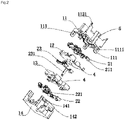
- a 3D multi-side socket unit comprises a socket interior within a housing.
- the socket interior comprises clapboards and plug bush conductive sheets.
- the clapboards include a first clapboard 11, a second clapboard 12, a third clapboard 13 and a fourth clapboard 14 which are sequentially stacked.
- the plug bush conductive sheets comprise a live wire plug bush conductive sheet 21 arranged between the first clapboard 11 and the second clapboard 12, an earth wire plug bush conductive sheet 23 arranged between the second clapboard 12 and the third clapboard 13, and a naught wire plug bush conductive sheet 22 arranged between the third clapboard 13 and the fourth clapboard 14.
- the naught wire plug bush conductive sheet 22 is provided between the first clapboard 11 and the second clapboard 12, the earth plug bush conductive sheet 23 is provided between the second clapboard 12 and the third clapboard 13, and the live wire plug bush conductive sheet 21 is provided between the third clapboard 13 and the fourth clapboard 14.
- the positions where each plug bush conductive sheet is located is not limited by the disclosure, as long as the positions of each plug bush conductive sheet satisfy the positive order or the reverse order of "live”, “earth” and "naught”.
- the positions where each clapboard is located is not limited by the disclosure, as long as the positions of each clapboard satisfy the positive order or the reverse order of "first”, “second” , "third” and "fourth”.
- the live plug bush conductive sheet 21, the naught wire plug bush conductive sheet 22 and the earth plug bush conductive sheet 23 are parallel to each other, so that the structure of the 3D multi-side socket unit is very simple, comparing with a structure that live plug bush conductive sheet, the naught wire plug bush conductive sheet and the earth plug bush conductive sheet are crossed with each other.
- a buckle structure is provided between the first clapboard 11 and the fourth clapboard 14 which are at the opposite ends, to form a tight integral socket interior by mutually stacking each clapboard and each plug bush conductive sheet and making them press against each other.
- the buckle structure may comprise a buckle arm 111 provided at the edge of the first clapboard 11 and extending towards the fourth clapboard 14, with a clamping slot 1111 provided on the buckle arm 111, and a clamping projection 141 that engages with the clamping slot 1111 of the buckle arm 111 provided on the fourth clapboard 14. It can be understood that the buckle arm could also be provided on the fourth clapboard 14, while the clamping projection 141 could be provided on the first clapboard 11.
- buckle arms are provided on the fourth clapboard 14 but not in a straight line.
- the buckle arms respectively surrounds the peripheries of the second clapboard 12 and the third clapboard 13 after the socket interior is assembled; of course, it can be understood that the buckle arms may also buckle with the clamping projection 141 of the fourth clapboard 14 after respectively passing through the second clapboard 12 and the third clapboard 13.
- the positioning mechanism comprises second positioning posts 91 provided on a surface of the first clapboard 11 facing towards the live wire plug bush conductive sheet 21, on a surface of the second clapboard 12 facing towards the earth wire plug bush conductive sheet 23, and on a surface of the third clapboard 13 facing towards the naught wire plug bush conductive sheet 22; and second positioning holes 92 provided on the live wire plug bush conductive sheet 21, on the earth wire plug bush conductive sheet 23 and on the naught wire plug bush conductive sheet 22 which engage with the second positioning posts 91.
- the number of the second positioning posts 91 on each clapboard is at least two, so that the conductive sheets can be accurately installed on each clapboard.
- the second positioning posts 91 could also be provided on a surface of the fourth clapboard 14 facing towards the naught wire plug bush conductive sheet 22, on a surface of the third clapboard 13 facing towards the earth wire plug bush conductive sheet 23, and on a surface of the second clapboard 12 facing towards the live wire plug bush conductive sheet 21, or simultaneously provided on the opposite two surfaces of corresponding clapboards.
- each of the side surfaces of the second clapboard 12, the third clapboard 13 and the fourth clapboard 14 which are in the same orientation is recessed inward to form a wiring slot 4.
- a first press block 142 spaning across the wiring slot 4.
- the first wiring pin 211 and the second wiring pin 221 are located within the wiring slots 4, leading to the convenience placement of conductive wires such as wiring pins; and a third wiring pin 231 is provided on the earth wire plug bush conductive sheet 23, and the third wiring pin 231 is bent against the earth wire plug bush conductive sheet 23, and the third wiring pin 231 passes through the third clapboard 13 and the fourth clapboard 14 and exposed outside the fourth clapboard 14 after the socket interior is assembled.
- the socket interior is also provided with a USB circuit board 61 and a heavy-current switch circuit board 62.
- a fixed bracket is extended from a surface of the first clapboard 11 far away from the second clapboard 12 and is configured to lay up the above circuit boards; or a fixed bracket is extended from a surface of the fourth clapboard 14 far away from the third clapboard 13 and is configured to lay up the above circuit boards.
- the USB circuit board 61 and the heavy-current switch circuit board 62 are provided on the surface of the first clapboard 11 far away from the second clapboard 12
- the isolating tendons 112 are also correspondingly provided on this surface of the fourth clapboard 14, and meanwhile, the wiring slots 4 are provided on the first clapboard 11, the second clapboard 12 and the third clapboard 13, while the first press block 142 is provided at the position on the first clapboard 11 where it snaps across the wiring slot 4.
- a lead wire limit slot 5 is also provided on the isolating tendons
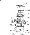
- Fig. 4 is the exploded view of the housing and the socket interior of the 3D multi-side socket unit.
- the housing comprises a lower housing 81 with an opening and an upper cover 82 that can close the opening.
- the upper cover 82 correspond to the USB circuit board 61 and the heavy-current switch circuit board 62 of the socket interior, and the upper cover 82 is provided with a USB structure and a switch that turns on/off the 3D multi-side socket unit.
- the bottom surface of the lower housing 81 opposing the upper cover 82 is a bearing surface 811. Considering the function of the bearing surface 811, and in order to reduce the volume of the 3D multi-side socket unit, no jacks are provided on the bearing surface 811.
- One side surface of the lower housing 81 is provided with a threading hole and defined as a threading surface, and the threading hole 8132 corresponds to the first press block 142, so as to make it easier to lead the wires out from the rocket interior.
- a second press block 8131 on the inner side of the treading surface 813 of the lower housing 81 there is also provided with a second press block 8131.
- the second press block 8131 forms as a group with the first press block 142 provided on the clapboard. And between the first press block 142 and the second press block 8131 are formed holes for passing conductive cables, and via this arrangement the quantity of wires inside the socket interior is reduced and the volume of the 3D multi-side socket unit is also reduced.
- a protective door module 7 is provided between the socket interior and the jack surface 812, and to make it easier to install the protective door module 7, a sticking post 143 is provided on the side surface of the socket interior.
- the sticking post 143 is used to install the socket interior and the protective door module 7, and then the socket interior installed with the protective door module 7 is placed into the lower housing 81 as a whole, to make the threading surface 813 of the lower housing 81 to correspond to the press block 142 of the socket interior, and successively the upper cover 82 is covered to make a clamping joint 1121 of the socket interior directly plug into a blind hole slot (not shown in the figures) in the inner side of the upper cover 82, and thereby a convenient installation has been completed.
- said housing may be of other forms.
- the housing could comprise a middle body with two openings each at its two opposite ends and two end caps each covering one of the two openings of the middle body, that is, the lower housing 81 in Fig. 4 is divided into two parts, and for this no further elaboration is needed here.
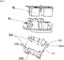
- Fig. 6 is an exploded view of a housing and a socket interior of a 3D multi-side socket unit.
- This 3D multi-side socket unit differs from that of example 1 in that an insulation board 63 is provided between the first clapboard 11 and the circuit boards, that is, the socket interior is provided with an insulation board 63 that insulates the USB circuit board 61 and the heavy-current switch circuit board 62 from the first clapboard 11.
- the insulation board 63 is configured to increase the electric clearance between the circuit boards and the live wire plug bush conductive sheet 21 or the electric clearance between the circuit boards and the naught wire plug bush conductive sheet 22 to make it comply with the regulations of relevant standards.
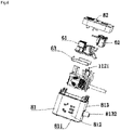
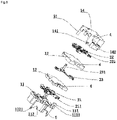
- Fig. 7 is the exploded view of the socket interior.
- the socket interior differs from that of example 1 in that the buckle structure between the fourth clapboard 14 and the first clapboard 11 is removed, instead, a positioning post 31 is provided on the surface of the first clapboard 11 opposing the second clapboard 12, and a positioning hole 32 which engages with the positioning post 31 is provided on the second clapboard 12 and the third clapboard 13, respectively.
- a screwed hole 311 which can be locked with a screw is provided on an end surface of the positioning post 31.
- a counter bore 33 is provided on the fourth clapboard 14 that corresponds to the screwed hole 311.
- the positioning post 31 may also be provided on the surface of the fourth clapboard 14 opposing the third clapboard 13 (not shown in the figures), and the positioning hole 32 that engages with the positioning post 31 is provided on the second clapboard 12 and the third clapboard 13, respectively.
- the screwed hole 311 which can be locked with the screw 34 is provided on an end surface of the positioning post 31, and the counter bore 33 that corresponds to the screwed hole 311 is provided on the first clapboard 11.
- the positioning post 31 on the first clapboard 11 is allowed to pass through the positioning holes 32 of the second clapboard 12 and the third clapboard 13 in sequence, and then to abut with the counter bore 33 on the fourth clapboard 14.
- the screw 34 can be used to lock into the screwed hole 311, and thereby the fixation and installation of the socket interior are realized.
- Fig. 8 is the exploded view of the socket interior, which differs from example 1 also in the socket interior.
- example 4 uses not only the buckle structure but also the structure of the positioning post 31.
- the buckle arms 111 are provided at the edge of the first clapboard 11 and extend towards the fourth clapboard 14. And the buckle arm is provided at each of three corners of the first clapboard 11 and the counter bore 33 is provided at the last corner of the first clapboard 11.
- the clamping slot 1111 is provided on each of the buckle arms 111, while the clamping projection 141 that snaps with the clamping slot 1111 of the buckle arm 111 is provided at each of the corresponding three corners of the fourth clapboard 14, and the positioning post 31 that corresponds to the counter bore 33 is provided at the last corner of the fourth clapboard 14. It can be understood that the number of the buckle arm 111 could be one or two, while the number of the positioning post 31 could be two or three.
- each clapboard is superposed over one another, and the screw 34 is locked into the screwed hole 311 of the positioning post 31 after the positioning post 31 corresponds to the counter bore 33, while the clamping slot 1111 of the buckle arm 111 snaps with the clamping projection 141, thereby the assembly of the socket interior is finished.
- no positioning mechanism is provided here. It can be understood that, according to the actual practice, a positioning mechanism as disclosed in example 1 can be provided between each clapboard and its corresponding conductive sheet.
Landscapes
- Details Of Connecting Devices For Male And Female Coupling (AREA)
- Coupling Device And Connection With Printed Circuit (AREA)
- Engineering & Computer Science (AREA)
- Microelectronics & Electronic Packaging (AREA)
- Connector Housings Or Holding Contact Members (AREA)
Claims (11)
- Dreidimensionale mehrseitige Steckdoseneinheit, umfassend:ein Gehäuse; undeinen Steckdoseninnenbereich, der innerhalb des Gehäuses bereitgestellt ist, wobei
der Steckdoseninnenbereich umfasst:Verschalungen, umfassend eine erste Verschalung (11), eine zweite Verschalung (12), eine dritte Verschalung (13) und eine vierte Verschalung (14), die nacheinander gestapelt sind, undeine unter Spannung stehende leitende Steckbuchsenplatte (21), eine leitende Nullleiter-Steckbuchsenplatte (22) und eine leitende Erdleiter-Steckbuchsenplatte (23);wobei das Gehäuse mindestens zwei Buchsenflächen umfasst, auf denen jeweils Buchsen bereitgestellt sind, wobei jede Buchse einer der unter Spannung stehenden leitenden Steckbuchsenplatte (21), der leitenden Nullleiter-Steckbuchsenplatte (22) und der leitenden Erdleiter-Steckbuchsenplatte (23) entspricht; wobeidie leitende Nullleiter-Steckbuchsenplatte (22) zwischen der ersten Verschalung (11) und der zweiten Verschalung (12) bereitgestellt ist, die leitende Erdleiter-Steckbuchsenplatte (23) zwischen der zweiten Verschalung (12) und der dritten Verschalung (13) bereitgestellt ist und die unter Spannung stehende leitende Steckbuchsenplatte (21) zwischen der dritten Verschalung (13) und der vierten Verschalung (14) bereitgestellt ist; oder die unter Spannung stehende leitende Steckbuchsenplatte (21) zwischen der ersten Verschalung (11) und der zweiten Verschalung (12) bereitgestellt ist, die leitende Erdleiter-Steckbuchsenplatte (23) zwischen der zweiten Verschalung (12) und der dritten Verschalung (13) bereitgestellt ist und die leitende Nullleiter-Steckbuchsenplatte (22) zwischen der dritten Verschalung (13) und der vierten Verschalung (14) bereitgestellt ist; dadurch gekennzeichnet, dassfalls die dreidimensionale mehrseitige Steckdoseneinheit Schnallenriemen umfasst, die Schnallenriemen zwischen der ersten Verschalung (11) und der vierten Verschalung (14) bereitgestellt sind, und die Schnallenriemen aneinander geschnallt werden können und jede Verschalung und die entsprechenden leitenden Platten dagegen gedrückt werden, wenn der Schnallenriemen der ersten Verschalung (11) an denjenigen der vierten Verschalung (14) derart geschnallt wird, dass ein dichter integraler Steckdoseninnenbereich gebildet wird, indem jede Verschalung und jede leitende Steckbuchsenplatte wechselseitig gestapelt werden und bewirkt wird, dass diese gegeneinander drücken;wobei ein Klemmschlitz (1111) an dem freien Ende des Schnallenriemens auf der ersten Verschalung (11) bereitgestellt ist, ein an den Klemmschlitz (1111) zu klemmender Klemmvorsprung (141) an dem freien Ende des Schnallenriemens auf der vierten Verschalung (14) bereitgestellt ist; oder ein Klemmschlitz (1111) an dem freien Ende des Schnallenriemens auf der vierten Verschalung (14) bereitgestellt ist, ein an den Klemmschlitz (1111) zu klemmender Klemmvorsprung (141) an dem freien Ende des Schnallenriemens auf der ersten Verschalung (11) bereitgestellt ist;
und/oderfalls die dreidimensionale mehrseitige Steckdoseneinheit einen ersten Positionierungsstift (31) und eine erste Positionierungsöffnung (32) umfasst, und der erste Positionierungsstift (31) auf der ersten Verschalung (11) oder auf der vierten Verschalung (14) bereitgestellt ist und die erste Positionierungsöffnung (32) auf anderen Verschalungen mit Ausnahme der mit dem ersten Positionierungsstift (31) bereitgestellten bereitgestellt ist und den ersten Positionierungsstift (31) derart in Eingriff nimmt, dass ein dichter integraler Steckdoseninnenbereich gebildet wird, indem jede Verschalung und jede leitende Steckbuchsenplatte wechselseitig gestapelt werden und bewirkt wird, dass diese gegeneinander drücken;wobei eine mit einer Schraube (34) zu verriegelnde geschraubte Öffnung (311) an dem freien Ende des ersten Positionierungsstifts (31) bereitgestellt ist und eine Gegenbohrung (33) zum Aufnehmen der Schraube auf der Verschalung, wo sich das freie Ende des ersten Positionierungsstifts (31) befindet, bereitgestellt ist. - Dreidimensionale mehrseitige Steckdoseneinheit nach Anspruch 1, wobei die unter Spannung stehende leitende Steckbuchsenplatte (21), die leitende Nullleiter-Steckbuchsenplatte (22) und die leitende Erdleiter-Steckbuchsenplatte (23) parallel zueinander sind.
- Dreidimensionale mehrseitige Steckdoseneinheit nach Anspruch 1, wobeidie Schnallenriemen den Umfang der zweiten Verschalung (12) und der dritten Verschalung (13) umgeben; oderdie Schnallenriemen durch die zweite Verschalung (12) und die dritte Verschalung (13) hindurchführen.
- Dreidimensionale mehrseitige Steckdoseneinheit nach Anspruch 1, wobeieine feste Klammer, die konfiguriert ist, um eine Platine zu verstärken, sich von einer Fläche der ersten Verschalung (11) weit entfernt von der zweiten Verschalung (12) erstreckt; oder eine feste Klammer, die konfiguriert ist, um eine Platine zu verstärken, sich von einer Fläche der vierten Verschalung (14) weit entfernt von der dritten Verschalung (13) erstreckt;die Platine wahlweise eine USB-Platine (61) und/oder eine Starkstromschalter-Platine (62) umfasst; der feste Träger Isolierglieder (112) umfasst, die konfiguriert sind, um die Starkstromschalter-Platine (62) und die USB-Platine (61) zu isolieren; und/odereine Isolierplatte (63) auf der ersten Verschalung (11) oder der vierten Verschalung (14) mit Platinen installiert bereitgestellt ist und die Isolierplatte (63) konfiguriert ist, um die USB-Platine (61) und die Starkstromschalter-Platine (62) zu isolieren.
- Dreidimensionale mehrseitige Steckdoseneinheit nach Anspruch 1 oder 4, wobei eine Gewindeöffnung (8132), die zum Führen von leitenden Kabeln nach außen konfiguriert ist, auf einer Seitenfläche des Gehäuses bereitgestellt ist und ein Leitungsschlitz (4) in einer Seitenfläche des Steckdoseninnenbereichs, die der Gewindeöffnung (8132) entspricht, nach innen eingelassen ist.
- Dreidimensionale mehrseitige Steckdoseneinheit nach Anspruch 5, wobei ein erster Kontaktstift (211) auf der unter Spannung stehenden leitenden Steckbuchsenplatte (21) bereitgestellt ist, ein zweiter Kontaktstift (221) auf der leitenden Nullleiter-Steckbuchsenplatte (22) bereitgestellt ist und sowohl der erste Kontaktstift (211) als auch der zweite Kontaktstift (221) im Leitungsschlitz (4) bereitgestellt sind;
wahlweise ein erster Pressblock (142) an einer Seitenfläche des Steckdoseninnenbereichs, die der Gewindeöffnung (8132) gegenüberliegt, bereitgestellt ist, ein zweiter Pressblock (8131) unter der Gewindeöffnung (8132) auf der Innenseite des Gehäuses bereitgestellt ist und der erste Pressblock (142) und der zweite Pressblock (8131) sich gegenseitig kontaktieren, wenn der Steckdoseninnenbereich im Gehäuse installiert ist. - Dreidimensionale mehrseitige Steckdoseneinheit nach Anspruch 6, wobei, wenn sich der erste Pressblock (142) und der zweite Pressblock (8131) gegenseitig kontaktieren, eine Öffnung, die zum Durchlassen von leitenden Leitungen durch die Gewindeöffnung (8132) konfiguriert ist, zwischen den gegenüberliegenden Flanken des erstes Pressblocks (142) und des zweiten Pressblocks (8131) bereitgestellt ist.
- Dreidimensionale mehrseitige Steckdoseneinheit nach Anspruch 1, wobeiein dritter Kontaktstift (231) auf der leitenden Erdleiter-Steckbuchsenplatte (23) bereitgestellt ist und gekrümmt ist und sich zur vierten Verschalung (14) erstreckt und der dritte Kontaktstift (231) in die vierte Verschalung (14) eindringt; oderein dritter Kontaktstift (231) auf der leitenden Erdleiter-Steckbuchsenplatte (23) bereitgestellt ist und gekrümmt ist und sich zur ersten Verschalung (11) erstreckt und der dritte Kontaktstift (231) in die erste Verschalung (11) eindringt.
- Dreidimensionale mehrseitige Steckdoseneinheit nach Anspruch 1, wobei ein schützendes Türmodul (7) zwischen dem Steckdoseninnenbereich und der Innenseite des Gehäuses mit der Buchse bereitgestellt ist und das schützende Türmodul (7) konfiguriert sind, um die Buchse zu schützen;
wahlweise ein Haftstift (143) an einer Seitenfläche des Steckdoseninnenbereichs gegenüber der Innenseite des Gehäuses bereitgestellt ist und der Haftstift (143) konfiguriert ist, um das schützende Türmodul (7) auszurichten. - Dreidimensionale mehrseitige Steckdoseneinheit nach Anspruch 4, wobei ein Klemmgelenk (1121) an einer Seite des Isolierglieds (112), die der oberen Abdeckung zugewandt ist, bereitgestellt ist, das Klemmgelenk (1121) sich zur oberen Abdeckung (82) erstreckt und eine Schattennut, die mit dem Klemmgelenk (1121) in Eingriff steht, an einer entsprechenden Innenfläche des oberen Gehäusedeckels (82) bereitgestellt ist.
- Dreidimensionale mehrseitige Steckdoseneinheit nach Anspruch 1, wobei ein Positionierungsmechanismus zwischen jeder Verschalung und jeder entsprechenden leitenden Platte, die abwechselnd gestapelt sind, bereitgestellt ist und der Positionierungsmechanismus konfiguriert ist, um jede leitende Platte zu jeder entsprechenden Verschalung auszurichten;
der Positionierungsmechanismus wahlweise einen zweiten Positionierungsstift (91), der auf der Verschalung bereitgestellt ist, und eine zweite Positionierungsöffnung (92) umfasst, die jeweils auf der unter Spannung stehenden leitenden Steckbuchsenplatte (21), der leitenden Nullleiter-Steckbuchsenplatte (22) und der leitenden Erdleiter-Steckbuchsenplatte (23) bereitgestellt sind, wobei zweite Positionierungsöffnungen (92) eins zu eins zweiten Positionierungsstiften (91) entsprechen und dieselben in Eingriff nehmen.
Applications Claiming Priority (2)
| Application Number | Priority Date | Filing Date | Title |
|---|---|---|---|
| CN201620043644.3U CN205355372U (zh) | 2016-01-18 | 2016-01-18 | 多面插座 |
| PCT/CN2017/076997 WO2017125095A1 (zh) | 2016-01-18 | 2017-03-16 | 立体转换器 |
Publications (3)
| Publication Number | Publication Date |
|---|---|
| EP3379656A1 EP3379656A1 (de) | 2018-09-26 |
| EP3379656A4 EP3379656A4 (de) | 2019-07-10 |
| EP3379656B1 true EP3379656B1 (de) | 2022-09-21 |
Family
ID=56176561
Family Applications (1)
| Application Number | Title | Priority Date | Filing Date |
|---|---|---|---|
| EP17741126.1A Active EP3379656B1 (de) | 2016-01-18 | 2017-03-16 | Dreidimensionaler wandler |
Country Status (5)
| Country | Link |
|---|---|
| US (1) | US10601192B2 (de) |
| EP (1) | EP3379656B1 (de) |
| JP (1) | JP2019517706A (de) |
| CN (1) | CN205355372U (de) |
| WO (1) | WO2017125095A1 (de) |
Families Citing this family (14)
| Publication number | Priority date | Publication date | Assignee | Title |
|---|---|---|---|---|
| CN205355372U (zh) | 2016-01-18 | 2016-06-29 | 公牛集团有限公司 | 多面插座 |
| CN106129696B (zh) * | 2016-08-10 | 2019-08-13 | 杭州鸿雁电器有限公司 | 一种模块化智能插座及其组装方法 |
| CN108232680B (zh) * | 2018-04-07 | 2023-09-22 | 佛山市顺德区信辉达电子有限公司 | 用于漏电保护插头的继电器架 |
| CN208284696U (zh) * | 2018-06-01 | 2018-12-25 | 深圳市联讯发科技有限公司 | 一种一体式立体插座 |
| CN109004424A (zh) * | 2018-08-02 | 2018-12-14 | 上海飞科电器股份有限公司 | 魔方多面插座 |
| NL2021785B1 (en) * | 2018-10-09 | 2020-05-13 | Designnest B V | Power outlet device |
| CN109742575B (zh) * | 2019-01-17 | 2024-02-27 | 深圳市航嘉驰源电气股份有限公司 | 一种方形插座 |
| CN109755790B (zh) * | 2019-03-20 | 2023-09-12 | 宁波奥博尔电器有限公司 | 一种多面立体插芯及具有该插芯的球型插座 |
| CN110544844B (zh) * | 2019-08-30 | 2025-06-27 | 公牛集团股份有限公司 | 一种魔方插座 |
| CN112542715B (zh) * | 2019-09-23 | 2025-11-04 | 北京小米移动软件有限公司 | 多面体插座的强电模块及多面体插座 |
| CN112542722B (zh) * | 2019-09-23 | 2025-11-04 | 北京小米移动软件有限公司 | 多面体插座及多面体插座的装配方法 |
| CN112968334B (zh) * | 2021-03-16 | 2025-05-27 | 东莞市万旅电器有限公司 | 一种模块化转换器及具有其的插座 |
| CN215119337U (zh) * | 2021-05-06 | 2021-12-10 | 黄志福 | 端子一体式安全插座 |
| CN219226693U (zh) * | 2023-02-08 | 2023-06-20 | 欧普照明电器(中山)有限公司 | 插座组件及魔方插座 |
Citations (1)
| Publication number | Priority date | Publication date | Assignee | Title |
|---|---|---|---|---|
| US20100167580A1 (en) * | 2008-12-30 | 2010-07-01 | Dominic Kan Nam Lee | Three Way Electrical Wall Tap with Light Indicator |
Family Cites Families (18)
| Publication number | Priority date | Publication date | Assignee | Title |
|---|---|---|---|---|
| US4313646A (en) * | 1980-02-25 | 1982-02-02 | Amp Incorporated | Power distribution system |
| US5094630A (en) * | 1991-02-25 | 1992-03-10 | Jammet Jean Claude | Multiple socket attachment |
| US5281172A (en) * | 1992-12-04 | 1994-01-25 | Pacomex Industries, Inc. | Electrical outlet adapter |
| US5383799A (en) * | 1993-03-26 | 1995-01-24 | Fladung; Philip E. | Multi-purpose plug-in electrical outlet adaptor |
| US6015303A (en) * | 1997-10-17 | 2000-01-18 | Hubbell Incorporated | Electrical receptacle assembly with multiple sites of dual snap-fit securement means |
| US6488540B2 (en) * | 2000-09-08 | 2002-12-03 | Heyco, Inc. | Multi-receptacle electrical outlet |
| US6929514B1 (en) * | 2004-05-17 | 2005-08-16 | Chao Da Trading Co., Ltd. | Socket with non-connecting terminal |
| US20060216986A1 (en) | 2005-03-25 | 2006-09-28 | Abbas Amiri-Hezaveh | Compact signal distribution device |
| CN201629446U (zh) | 2010-02-11 | 2010-11-10 | 黄浩波 | 多功能可叠加插座 |
| CN203721952U (zh) * | 2013-12-16 | 2014-07-16 | 苏州波特利五金照明电器有限公司 | 一种方形插座内部结构 |
| CN203787656U (zh) | 2013-12-30 | 2014-08-20 | 慈溪市清风电子有限公司 | 一种立式插座 |
| US9306349B2 (en) | 2014-01-21 | 2016-04-05 | Allocacoc Corporation | Construction of an alternating current (AC) power socket |
| JP2015138691A (ja) * | 2014-01-23 | 2015-07-30 | 株式会社Cjプライムショッピング | テーブルタップ |
| CN204304180U (zh) * | 2014-11-05 | 2015-04-29 | 慈溪市清风电子有限公司 | 一种魔方插座 |
| CN204349054U (zh) * | 2014-12-30 | 2015-05-20 | 国光电器股份有限公司 | 一种立体多面插座单元及组合插座 |
| CN204966859U (zh) | 2015-08-25 | 2016-01-13 | 广东顺科通信设备实业有限公司 | 一种反向开口屏蔽夹 |
| CN105207020A (zh) | 2015-09-28 | 2015-12-30 | 洛阳德威机电科技有限公司 | 一种魔方式组合插座及其方法 |
| CN205355372U (zh) * | 2016-01-18 | 2016-06-29 | 公牛集团有限公司 | 多面插座 |
-
2016
- 2016-01-18 CN CN201620043644.3U patent/CN205355372U/zh not_active Expired - Lifetime
-
2017
- 2017-03-16 US US16/064,985 patent/US10601192B2/en active Active
- 2017-03-16 JP JP2018538619A patent/JP2019517706A/ja active Pending
- 2017-03-16 EP EP17741126.1A patent/EP3379656B1/de active Active
- 2017-03-16 WO PCT/CN2017/076997 patent/WO2017125095A1/zh not_active Ceased
Patent Citations (1)
| Publication number | Priority date | Publication date | Assignee | Title |
|---|---|---|---|---|
| US20100167580A1 (en) * | 2008-12-30 | 2010-07-01 | Dominic Kan Nam Lee | Three Way Electrical Wall Tap with Light Indicator |
Also Published As
| Publication number | Publication date |
|---|---|
| US10601192B2 (en) | 2020-03-24 |
| EP3379656A4 (de) | 2019-07-10 |
| WO2017125095A1 (zh) | 2017-07-27 |
| JP2019517706A (ja) | 2019-06-24 |
| EP3379656A1 (de) | 2018-09-26 |
| US20180323558A1 (en) | 2018-11-08 |
| CN205355372U (zh) | 2016-06-29 |
Similar Documents
| Publication | Publication Date | Title |
|---|---|---|
| EP3379656B1 (de) | Dreidimensionaler wandler | |
| EP2584615A1 (de) | Kombinierbox | |
| CN103116051A (zh) | 插拔式电表箱 | |
| JP3285316B2 (ja) | 太陽電池モジュールの端子ボックス | |
| CN210668809U (zh) | 多面体插座 | |
| CN205335495U (zh) | 一种电连接器 | |
| CN204376000U (zh) | 一种控制器的端子盖及控制器 | |
| JP6452402B2 (ja) | 蓄電装置 | |
| CN112542722B (zh) | 多面体插座及多面体插座的装配方法 | |
| CN213936806U (zh) | 电源插头 | |
| CN212343256U (zh) | 一种电线接线盒 | |
| CN201616538U (zh) | 线缆组合体及其应用的线缆连接器 | |
| CN222601961U (zh) | 接线盒及电源分配模块 | |
| CN212366296U (zh) | 一种魔方插座 | |
| CN112542715B (zh) | 多面体插座的强电模块及多面体插座 | |
| CN223206478U (zh) | 一种接线端子、并网箱及光伏电站 | |
| CN221509529U (zh) | 一种光伏组件三分体接线盒 | |
| CN215377733U (zh) | 一种模块式大电流连接器 | |
| CN218602787U (zh) | 一种模块化的插座适配器 | |
| CN219717318U (zh) | 一种能够提高装配效率的伺服编码连接器 | |
| CN213460140U (zh) | 一种穿墙式接线端子及具有其的低压开关柜 | |
| US12394930B2 (en) | Socket module | |
| CN222654381U (zh) | 一种多面体插座 | |
| CN222785530U (zh) | 一种多孔位的插排 | |
| CN220065609U (zh) | 一种线束保险丝 |
Legal Events
| Date | Code | Title | Description |
|---|---|---|---|
| STAA | Information on the status of an ep patent application or granted ep patent |
Free format text: STATUS: THE INTERNATIONAL PUBLICATION HAS BEEN MADE |
|
| PUAI | Public reference made under article 153(3) epc to a published international application that has entered the european phase |
Free format text: ORIGINAL CODE: 0009012 |
|
| STAA | Information on the status of an ep patent application or granted ep patent |
Free format text: STATUS: REQUEST FOR EXAMINATION WAS MADE |
|
| 17P | Request for examination filed |
Effective date: 20180621 |
|
| AK | Designated contracting states |
Kind code of ref document: A1 Designated state(s): AL AT BE BG CH CY CZ DE DK EE ES FI FR GB GR HR HU IE IS IT LI LT LU LV MC MK MT NL NO PL PT RO RS SE SI SK SM TR |
|
| AX | Request for extension of the european patent |
Extension state: BA ME |
|
| XX | Miscellaneous (additional remarks) |
Free format text: A REQUEST FOR RESTORATION OF THE RIGHT OF PRIORITY BY THE EPO AS DESIGNATED OFFICE HAS BEEN GRANTED (R. 49TER.2 PCT, ART.122 EPC). |
|
| RIN1 | Information on inventor provided before grant (corrected) |
Inventor name: ZHANG, JIALU Inventor name: WANG, HUIJIU Inventor name: YAN, LEI Inventor name: DENG, HAO |
|
| DAV | Request for validation of the european patent (deleted) | ||
| DAX | Request for extension of the european patent (deleted) | ||
| REG | Reference to a national code |
Ref country code: DE Ref legal event code: R079 Ref document number: 602017061964 Country of ref document: DE Free format text: PREVIOUS MAIN CLASS: H01R0013514000 Ipc: H01R0024220000 |
|
| A4 | Supplementary search report drawn up and despatched |
Effective date: 20190606 |
|
| RIC1 | Information provided on ipc code assigned before grant |
Ipc: H01R 25/00 20060101ALI20190531BHEP Ipc: H01R 13/46 20060101ALI20190531BHEP Ipc: H01R 24/22 20110101AFI20190531BHEP Ipc: H01R 31/02 20060101ALI20190531BHEP Ipc: H01R 13/506 20060101ALI20190531BHEP Ipc: H01R 13/514 20060101ALI20190531BHEP |
|
| STAA | Information on the status of an ep patent application or granted ep patent |
Free format text: STATUS: EXAMINATION IS IN PROGRESS |
|
| 17Q | First examination report despatched |
Effective date: 20201218 |
|
| GRAP | Despatch of communication of intention to grant a patent |
Free format text: ORIGINAL CODE: EPIDOSNIGR1 |
|
| STAA | Information on the status of an ep patent application or granted ep patent |
Free format text: STATUS: GRANT OF PATENT IS INTENDED |
|
| INTG | Intention to grant announced |
Effective date: 20220420 |
|
| INTG | Intention to grant announced |
Effective date: 20220420 |
|
| GRAS | Grant fee paid |
Free format text: ORIGINAL CODE: EPIDOSNIGR3 |
|
| GRAA | (expected) grant |
Free format text: ORIGINAL CODE: 0009210 |
|
| STAA | Information on the status of an ep patent application or granted ep patent |
Free format text: STATUS: THE PATENT HAS BEEN GRANTED |
|
| AK | Designated contracting states |
Kind code of ref document: B1 Designated state(s): AL AT BE BG CH CY CZ DE DK EE ES FI FR GB GR HR HU IE IS IT LI LT LU LV MC MK MT NL NO PL PT RO RS SE SI SK SM TR |
|
| REG | Reference to a national code |
Ref country code: GB Ref legal event code: FG4D |
|
| XX | Miscellaneous (additional remarks) |
Free format text: A REQUEST FOR RESTORATION OF THE RIGHT OF PRIORITY BY THE EPO AS DESIGNATED OFFICE HAS BEEN GRANTED (R. 49TER.2 PCT, ART.122 EPC). |
|
| REG | Reference to a national code |
Ref country code: CH Ref legal event code: EP |
|
| REG | Reference to a national code |
Ref country code: IE Ref legal event code: FG4D |
|
| REG | Reference to a national code |
Ref country code: DE Ref legal event code: R096 Ref document number: 602017061964 Country of ref document: DE |
|
| REG | Reference to a national code |
Ref country code: AT Ref legal event code: REF Ref document number: 1520436 Country of ref document: AT Kind code of ref document: T Effective date: 20221015 |
|
| REG | Reference to a national code |
Ref country code: LT Ref legal event code: MG9D |
|
| REG | Reference to a national code |
Ref country code: NL Ref legal event code: MP Effective date: 20220921 |
|
| PG25 | Lapsed in a contracting state [announced via postgrant information from national office to epo] |
Ref country code: SE Free format text: LAPSE BECAUSE OF FAILURE TO SUBMIT A TRANSLATION OF THE DESCRIPTION OR TO PAY THE FEE WITHIN THE PRESCRIBED TIME-LIMIT Effective date: 20220921 Ref country code: RS Free format text: LAPSE BECAUSE OF FAILURE TO SUBMIT A TRANSLATION OF THE DESCRIPTION OR TO PAY THE FEE WITHIN THE PRESCRIBED TIME-LIMIT Effective date: 20220921 Ref country code: NO Free format text: LAPSE BECAUSE OF FAILURE TO SUBMIT A TRANSLATION OF THE DESCRIPTION OR TO PAY THE FEE WITHIN THE PRESCRIBED TIME-LIMIT Effective date: 20221221 Ref country code: LV Free format text: LAPSE BECAUSE OF FAILURE TO SUBMIT A TRANSLATION OF THE DESCRIPTION OR TO PAY THE FEE WITHIN THE PRESCRIBED TIME-LIMIT Effective date: 20220921 Ref country code: LT Free format text: LAPSE BECAUSE OF FAILURE TO SUBMIT A TRANSLATION OF THE DESCRIPTION OR TO PAY THE FEE WITHIN THE PRESCRIBED TIME-LIMIT Effective date: 20220921 Ref country code: FI Free format text: LAPSE BECAUSE OF FAILURE TO SUBMIT A TRANSLATION OF THE DESCRIPTION OR TO PAY THE FEE WITHIN THE PRESCRIBED TIME-LIMIT Effective date: 20220921 |
|
| REG | Reference to a national code |
Ref country code: AT Ref legal event code: MK05 Ref document number: 1520436 Country of ref document: AT Kind code of ref document: T Effective date: 20220921 |
|
| PG25 | Lapsed in a contracting state [announced via postgrant information from national office to epo] |
Ref country code: HR Free format text: LAPSE BECAUSE OF FAILURE TO SUBMIT A TRANSLATION OF THE DESCRIPTION OR TO PAY THE FEE WITHIN THE PRESCRIBED TIME-LIMIT Effective date: 20220921 Ref country code: GR Free format text: LAPSE BECAUSE OF FAILURE TO SUBMIT A TRANSLATION OF THE DESCRIPTION OR TO PAY THE FEE WITHIN THE PRESCRIBED TIME-LIMIT Effective date: 20221222 |
|
| PG25 | Lapsed in a contracting state [announced via postgrant information from national office to epo] |
Ref country code: SM Free format text: LAPSE BECAUSE OF FAILURE TO SUBMIT A TRANSLATION OF THE DESCRIPTION OR TO PAY THE FEE WITHIN THE PRESCRIBED TIME-LIMIT Effective date: 20220921 Ref country code: RO Free format text: LAPSE BECAUSE OF FAILURE TO SUBMIT A TRANSLATION OF THE DESCRIPTION OR TO PAY THE FEE WITHIN THE PRESCRIBED TIME-LIMIT Effective date: 20220921 Ref country code: PT Free format text: LAPSE BECAUSE OF FAILURE TO SUBMIT A TRANSLATION OF THE DESCRIPTION OR TO PAY THE FEE WITHIN THE PRESCRIBED TIME-LIMIT Effective date: 20230123 Ref country code: ES Free format text: LAPSE BECAUSE OF FAILURE TO SUBMIT A TRANSLATION OF THE DESCRIPTION OR TO PAY THE FEE WITHIN THE PRESCRIBED TIME-LIMIT Effective date: 20220921 Ref country code: CZ Free format text: LAPSE BECAUSE OF FAILURE TO SUBMIT A TRANSLATION OF THE DESCRIPTION OR TO PAY THE FEE WITHIN THE PRESCRIBED TIME-LIMIT Effective date: 20220921 Ref country code: AT Free format text: LAPSE BECAUSE OF FAILURE TO SUBMIT A TRANSLATION OF THE DESCRIPTION OR TO PAY THE FEE WITHIN THE PRESCRIBED TIME-LIMIT Effective date: 20220921 |
|
| PG25 | Lapsed in a contracting state [announced via postgrant information from national office to epo] |
Ref country code: SK Free format text: LAPSE BECAUSE OF FAILURE TO SUBMIT A TRANSLATION OF THE DESCRIPTION OR TO PAY THE FEE WITHIN THE PRESCRIBED TIME-LIMIT Effective date: 20220921 Ref country code: PL Free format text: LAPSE BECAUSE OF FAILURE TO SUBMIT A TRANSLATION OF THE DESCRIPTION OR TO PAY THE FEE WITHIN THE PRESCRIBED TIME-LIMIT Effective date: 20220921 Ref country code: IS Free format text: LAPSE BECAUSE OF FAILURE TO SUBMIT A TRANSLATION OF THE DESCRIPTION OR TO PAY THE FEE WITHIN THE PRESCRIBED TIME-LIMIT Effective date: 20230121 Ref country code: EE Free format text: LAPSE BECAUSE OF FAILURE TO SUBMIT A TRANSLATION OF THE DESCRIPTION OR TO PAY THE FEE WITHIN THE PRESCRIBED TIME-LIMIT Effective date: 20220921 |
|
| REG | Reference to a national code |
Ref country code: DE Ref legal event code: R097 Ref document number: 602017061964 Country of ref document: DE |
|
| PG25 | Lapsed in a contracting state [announced via postgrant information from national office to epo] |
Ref country code: NL Free format text: LAPSE BECAUSE OF FAILURE TO SUBMIT A TRANSLATION OF THE DESCRIPTION OR TO PAY THE FEE WITHIN THE PRESCRIBED TIME-LIMIT Effective date: 20220921 Ref country code: AL Free format text: LAPSE BECAUSE OF FAILURE TO SUBMIT A TRANSLATION OF THE DESCRIPTION OR TO PAY THE FEE WITHIN THE PRESCRIBED TIME-LIMIT Effective date: 20220921 |
|
| PLBE | No opposition filed within time limit |
Free format text: ORIGINAL CODE: 0009261 |
|
| STAA | Information on the status of an ep patent application or granted ep patent |
Free format text: STATUS: NO OPPOSITION FILED WITHIN TIME LIMIT |
|
| PG25 | Lapsed in a contracting state [announced via postgrant information from national office to epo] |
Ref country code: DK Free format text: LAPSE BECAUSE OF FAILURE TO SUBMIT A TRANSLATION OF THE DESCRIPTION OR TO PAY THE FEE WITHIN THE PRESCRIBED TIME-LIMIT Effective date: 20220921 |
|
| 26N | No opposition filed |
Effective date: 20230622 |
|
| PG25 | Lapsed in a contracting state [announced via postgrant information from national office to epo] |
Ref country code: SI Free format text: LAPSE BECAUSE OF FAILURE TO SUBMIT A TRANSLATION OF THE DESCRIPTION OR TO PAY THE FEE WITHIN THE PRESCRIBED TIME-LIMIT Effective date: 20220921 |
|
| PG25 | Lapsed in a contracting state [announced via postgrant information from national office to epo] |
Ref country code: MC Free format text: LAPSE BECAUSE OF FAILURE TO SUBMIT A TRANSLATION OF THE DESCRIPTION OR TO PAY THE FEE WITHIN THE PRESCRIBED TIME-LIMIT Effective date: 20220921 |
|
| REG | Reference to a national code |
Ref country code: CH Ref legal event code: PL |
|
| GBPC | Gb: european patent ceased through non-payment of renewal fee |
Effective date: 20230316 |
|
| REG | Reference to a national code |
Ref country code: BE Ref legal event code: MM Effective date: 20230331 |
|
| PG25 | Lapsed in a contracting state [announced via postgrant information from national office to epo] |
Ref country code: LU Free format text: LAPSE BECAUSE OF NON-PAYMENT OF DUE FEES Effective date: 20230316 |
|
| REG | Reference to a national code |
Ref country code: IE Ref legal event code: MM4A |
|
| PG25 | Lapsed in a contracting state [announced via postgrant information from national office to epo] |
Ref country code: GB Free format text: LAPSE BECAUSE OF NON-PAYMENT OF DUE FEES Effective date: 20230316 |
|
| PG25 | Lapsed in a contracting state [announced via postgrant information from national office to epo] |
Ref country code: LI Free format text: LAPSE BECAUSE OF NON-PAYMENT OF DUE FEES Effective date: 20230331 Ref country code: IE Free format text: LAPSE BECAUSE OF NON-PAYMENT OF DUE FEES Effective date: 20230316 Ref country code: GB Free format text: LAPSE BECAUSE OF NON-PAYMENT OF DUE FEES Effective date: 20230316 Ref country code: CH Free format text: LAPSE BECAUSE OF NON-PAYMENT OF DUE FEES Effective date: 20230331 |
|
| PG25 | Lapsed in a contracting state [announced via postgrant information from national office to epo] |
Ref country code: BE Free format text: LAPSE BECAUSE OF NON-PAYMENT OF DUE FEES Effective date: 20230331 |
|
| PG25 | Lapsed in a contracting state [announced via postgrant information from national office to epo] |
Ref country code: IT Free format text: LAPSE BECAUSE OF FAILURE TO SUBMIT A TRANSLATION OF THE DESCRIPTION OR TO PAY THE FEE WITHIN THE PRESCRIBED TIME-LIMIT Effective date: 20220921 |
|
| PG25 | Lapsed in a contracting state [announced via postgrant information from national office to epo] |
Ref country code: BG Free format text: LAPSE BECAUSE OF FAILURE TO SUBMIT A TRANSLATION OF THE DESCRIPTION OR TO PAY THE FEE WITHIN THE PRESCRIBED TIME-LIMIT Effective date: 20220921 |
|
| PG25 | Lapsed in a contracting state [announced via postgrant information from national office to epo] |
Ref country code: BG Free format text: LAPSE BECAUSE OF FAILURE TO SUBMIT A TRANSLATION OF THE DESCRIPTION OR TO PAY THE FEE WITHIN THE PRESCRIBED TIME-LIMIT Effective date: 20220921 |
|
| PG25 | Lapsed in a contracting state [announced via postgrant information from national office to epo] |
Ref country code: CY Free format text: LAPSE BECAUSE OF FAILURE TO SUBMIT A TRANSLATION OF THE DESCRIPTION OR TO PAY THE FEE WITHIN THE PRESCRIBED TIME-LIMIT; INVALID AB INITIO Effective date: 20170316 |
|
| PG25 | Lapsed in a contracting state [announced via postgrant information from national office to epo] |
Ref country code: HU Free format text: LAPSE BECAUSE OF FAILURE TO SUBMIT A TRANSLATION OF THE DESCRIPTION OR TO PAY THE FEE WITHIN THE PRESCRIBED TIME-LIMIT; INVALID AB INITIO Effective date: 20170316 |
|
| PG25 | Lapsed in a contracting state [announced via postgrant information from national office to epo] |
Ref country code: TR Free format text: LAPSE BECAUSE OF FAILURE TO SUBMIT A TRANSLATION OF THE DESCRIPTION OR TO PAY THE FEE WITHIN THE PRESCRIBED TIME-LIMIT Effective date: 20220921 |
|
| PGFP | Annual fee paid to national office [announced via postgrant information from national office to epo] |
Ref country code: DE Payment date: 20260319 Year of fee payment: 10 |
|
| PGFP | Annual fee paid to national office [announced via postgrant information from national office to epo] |
Ref country code: FR Payment date: 20260320 Year of fee payment: 10 |