EP3379671A1 - Dispositif de commutation et son utilisation pour le pré-chargement - Google Patents
Dispositif de commutation et son utilisation pour le pré-chargement Download PDFInfo
- Publication number
- EP3379671A1 EP3379671A1 EP17162549.4A EP17162549A EP3379671A1 EP 3379671 A1 EP3379671 A1 EP 3379671A1 EP 17162549 A EP17162549 A EP 17162549A EP 3379671 A1 EP3379671 A1 EP 3379671A1
- Authority
- EP
- European Patent Office
- Prior art keywords
- resistor
- switches
- switch
- capacitors
- power supply
- Prior art date
- Legal status (The legal status is an assumption and is not a legal conclusion. Google has not performed a legal analysis and makes no representation as to the accuracy of the status listed.)
- Withdrawn
Links
Images


Classifications
-
- H—ELECTRICITY
- H02—GENERATION; CONVERSION OR DISTRIBUTION OF ELECTRIC POWER
- H02H—EMERGENCY PROTECTIVE CIRCUIT ARRANGEMENTS
- H02H9/00—Emergency protective circuit arrangements for limiting excess current or voltage without disconnection
- H02H9/001—Emergency protective circuit arrangements for limiting excess current or voltage without disconnection limiting speed of change of electric quantities, e.g. soft switching on or off
-
- H—ELECTRICITY
- H02—GENERATION; CONVERSION OR DISTRIBUTION OF ELECTRIC POWER
- H02J—ELECTRIC POWER NETWORKS; CIRCUIT ARRANGEMENTS OR SYSTEMS FOR SUPPLYING OR DISTRIBUTING ELECTRIC POWER; SYSTEMS FOR STORING ELECTRIC ENERGY
- H02J1/00—Circuit arrangements for DC mains or DC distribution networks
-
- H—ELECTRICITY
- H02—GENERATION; CONVERSION OR DISTRIBUTION OF ELECTRIC POWER
- H02M—APPARATUS FOR CONVERSION BETWEEN AC AND AC, BETWEEN AC AND DC, OR BETWEEN DC AND DC, AND FOR USE WITH MAINS OR SIMILAR POWER SUPPLY SYSTEMS; CONVERSION OF DC OR AC INPUT POWER INTO SURGE OUTPUT POWER; CONTROL OR REGULATION THEREOF
- H02M1/00—Details of apparatus for conversion
- H02M1/36—Means for starting or stopping converters
Definitions
- a charging of the capacitors is carried out, wherein the switching device limits the through-current to the maximum permissible through-current of the resistor by means of at least one electrical switch.
- the DC voltage network can be split into partial DC voltage networks by means of the switches.
- the switches can be designed as mechanical or electronic switches.
- a main switch can be electrically interposed between the secondary winding of the transformer and the resistor, which can be switched by means of the switching device.
- the capacitors may be components of intermediate circuits, which supply the electrical consumers via inverters, wherein the precharging the capacitors are charged via the resistor from operation.
- a charging or pre-charging of the capacitors can be carried out, wherein the switching device switches the maximum permissible through-current of the resistor by means of a time circuit of the main switch.
- the through-current in the resistor can be limited by the fact that only a single one of all switches is closed and all switches are successively closed successively to pre-charge their connected capacitors and each subsequent switch is closed only when the temperature at the resistor has dropped below a threshold.
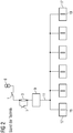
- Fig. 1 shows a first embodiment of a conventional electric power supply system.
- DC networks 11 are pre-charged via their so-called feed modules.
- the resistor 3 is bypassed with the bypass switch 5.
- the switch S1 can again be closed and opened in order to prevent an unwanted drop in the intermediate circuit voltage of the loads 17.1 and 17.2.
- the switch S2 is opened again.
- the switch S3 is closed in a third step Sr3 and reopened after the precharge has been completed. In this way any number of subnetworks can be precharged.
- the resistance 3 acting as a precharge resistance at the steps Sr1, Sr2 and Sr3 is made ineffective by closing the bypass switch 5 as an electrical resistance due to short-circuiting.
- all switches S1, S2, S3 can be closed again and the electric power supply system can go into operation. Electrical consumers 17 may also be referred to as "load".
- This embodiment has the advantage that the previously precharged capacitors 19 can not discharge during the charging time of the following capacitors 19, for example by parallel to the capacitors 19 balancing resistors, because the capacitors 19.1 and 19.2 via the bipolar transistors with insulated gates 11, 12 are constantly connected to the already preloaded parts of the DC power supply 11.
Landscapes
- Engineering & Computer Science (AREA)
- Power Engineering (AREA)
- Direct Current Feeding And Distribution (AREA)
- Charge And Discharge Circuits For Batteries Or The Like (AREA)
Priority Applications (3)
| Application Number | Priority Date | Filing Date | Title |
|---|---|---|---|
| EP17162549.4A EP3379671A1 (fr) | 2017-03-23 | 2017-03-23 | Dispositif de commutation et son utilisation pour le pré-chargement |
| PCT/EP2018/054727 WO2018172020A1 (fr) | 2017-03-23 | 2018-02-27 | Dispositif de commutation et son utilisation pour effectuer une précharge |
| EP18710359.3A EP3583688B1 (fr) | 2017-03-23 | 2018-02-27 | Dispositif de commutation et son utilisation pour effectuer une précharge |
Applications Claiming Priority (1)
| Application Number | Priority Date | Filing Date | Title |
|---|---|---|---|
| EP17162549.4A EP3379671A1 (fr) | 2017-03-23 | 2017-03-23 | Dispositif de commutation et son utilisation pour le pré-chargement |
Publications (1)
| Publication Number | Publication Date |
|---|---|
| EP3379671A1 true EP3379671A1 (fr) | 2018-09-26 |
Family
ID=58578812
Family Applications (2)
| Application Number | Title | Priority Date | Filing Date |
|---|---|---|---|
| EP17162549.4A Withdrawn EP3379671A1 (fr) | 2017-03-23 | 2017-03-23 | Dispositif de commutation et son utilisation pour le pré-chargement |
| EP18710359.3A Active EP3583688B1 (fr) | 2017-03-23 | 2018-02-27 | Dispositif de commutation et son utilisation pour effectuer une précharge |
Family Applications After (1)
| Application Number | Title | Priority Date | Filing Date |
|---|---|---|---|
| EP18710359.3A Active EP3583688B1 (fr) | 2017-03-23 | 2018-02-27 | Dispositif de commutation et son utilisation pour effectuer une précharge |
Country Status (2)
| Country | Link |
|---|---|
| EP (2) | EP3379671A1 (fr) |
| WO (1) | WO2018172020A1 (fr) |
Cited By (1)
| Publication number | Priority date | Publication date | Assignee | Title |
|---|---|---|---|---|
| EP3654507A1 (fr) * | 2018-11-16 | 2020-05-20 | Siemens Aktiengesellschaft | Composant électrique pouvant être surveillé doté d'au moins un alignement fonctionnel en tant que condensateur |
Citations (4)
| Publication number | Priority date | Publication date | Assignee | Title |
|---|---|---|---|---|
| US20070064366A1 (en) * | 2005-08-18 | 2007-03-22 | Hammond Peter W | System and method for limiting AC inrush current |
| US20120265378A1 (en) * | 2011-04-18 | 2012-10-18 | Advanced Rail Energy Storage, Llc | Combined synchronous and asynchronous power supply for electrically powered shuttle trains |
| EP2988404A1 (fr) * | 2014-08-22 | 2016-02-24 | ABB Technology AG | Précharge de convertisseur modulaire multi-niveaux |
| WO2016101381A1 (fr) * | 2014-12-25 | 2016-06-30 | 中山大洋电机股份有限公司 | Dispositif de charge rapide monté sur véhicule pour automobile électrique |
-
2017
- 2017-03-23 EP EP17162549.4A patent/EP3379671A1/fr not_active Withdrawn
-
2018
- 2018-02-27 EP EP18710359.3A patent/EP3583688B1/fr active Active
- 2018-02-27 WO PCT/EP2018/054727 patent/WO2018172020A1/fr not_active Ceased
Patent Citations (4)
| Publication number | Priority date | Publication date | Assignee | Title |
|---|---|---|---|---|
| US20070064366A1 (en) * | 2005-08-18 | 2007-03-22 | Hammond Peter W | System and method for limiting AC inrush current |
| US20120265378A1 (en) * | 2011-04-18 | 2012-10-18 | Advanced Rail Energy Storage, Llc | Combined synchronous and asynchronous power supply for electrically powered shuttle trains |
| EP2988404A1 (fr) * | 2014-08-22 | 2016-02-24 | ABB Technology AG | Précharge de convertisseur modulaire multi-niveaux |
| WO2016101381A1 (fr) * | 2014-12-25 | 2016-06-30 | 中山大洋电机股份有限公司 | Dispositif de charge rapide monté sur véhicule pour automobile électrique |
Cited By (1)
| Publication number | Priority date | Publication date | Assignee | Title |
|---|---|---|---|---|
| EP3654507A1 (fr) * | 2018-11-16 | 2020-05-20 | Siemens Aktiengesellschaft | Composant électrique pouvant être surveillé doté d'au moins un alignement fonctionnel en tant que condensateur |
Also Published As
| Publication number | Publication date |
|---|---|
| EP3583688A1 (fr) | 2019-12-25 |
| WO2018172020A1 (fr) | 2018-09-27 |
| EP3583688B1 (fr) | 2021-02-17 |
Similar Documents
| Publication | Publication Date | Title |
|---|---|---|
| EP2467927B1 (fr) | Methode de decharge du condensateur de bus dc d'un convertisseur avec un bus dc | |
| DE102017207102A1 (de) | Stationärspeicher zum Zwischenspeichern von elektrischer Energie in einem elektrischen Versorgungsnetz sowie Betriebsverfahren und Nachrüstmodul für den Stationärspeicher | |
| EP3501884A1 (fr) | Dispositif transformateur pour une station de charge destiné à la charge électrique de véhicules au moyen d'au moins deux points de charge | |
| DE102018106305A1 (de) | Wechselstromladung einer intelligenten Batterie | |
| DE102011003859A1 (de) | System zum Laden eines Energiespeichers und Verfahren zum Betrieb des Ladesystems | |
| WO2012107149A1 (fr) | Système de charge d'un accumulateur d'énergie et procédé de fonctionnement du système de charge | |
| DE112016006844T5 (de) | Batterietrennschaltungen und Verfahren zum Steuern einer Batterietrennschaltung | |
| AT510025A4 (de) | Antriebseinheit eines elektrofahrzeugs | |
| DE102016122655A1 (de) | Stromrichter und steuerungsverfahren | |
| EP3407449A1 (fr) | Réseau de tension continue redondant | |
| DE102019005621A1 (de) | Bordnetz für ein elektrisch antreibbares Kraftfahrzeug | |
| EP1918192B1 (fr) | Submersible | |
| EP3583674A1 (fr) | Montage optimal d'un système à tension continue et procédé en cas de défaillance du réseau d'alimentation | |
| DE102013017091A1 (de) | Energiespeichereinrichtung für einen Kraftwagen | |
| DE102015007264A1 (de) | Schnelles Übertragen von elektrischer Energie von einer Ladestation zu einem Verbraucher | |
| EP3583688B1 (fr) | Dispositif de commutation et son utilisation pour effectuer une précharge | |
| EP2733837A1 (fr) | Convertisseur | |
| DE102019123403A1 (de) | Verfahren zum Betreiben einer Hochvoltbatterie, Steuereinrichtung, Bordnetz sowie Kraftfahrzeug | |
| DE102011076787A1 (de) | Energieversorgung | |
| DE102019105310B4 (de) | Elektrischer Antrieb | |
| DE102014011795A1 (de) | Schaltungsanordnung und Verfahren zur Vorladung eines Hochvolt-Gleichspannungszwischenkreises in einem Kraftfahrzeug | |
| EP3407447A1 (fr) | Réseau de tension électrique continue à haute redondance | |
| EP3583672B1 (fr) | Précharge efficace de sections d'un réseau de tension continu | |
| WO2000028636A2 (fr) | Systeme d'accumulation d'energie | |
| DE102019119223A1 (de) | Verfahren und Ladegerät zur Netzeinspeisung mit einem Drei-Phasen-Transformator |
Legal Events
| Date | Code | Title | Description |
|---|---|---|---|
| PUAI | Public reference made under article 153(3) epc to a published international application that has entered the european phase |
Free format text: ORIGINAL CODE: 0009012 |
|
| AK | Designated contracting states |
Kind code of ref document: A1 Designated state(s): AL AT BE BG CH CY CZ DE DK EE ES FI FR GB GR HR HU IE IS IT LI LT LU LV MC MK MT NL NO PL PT RO RS SE SI SK SM TR |
|
| AX | Request for extension of the european patent |
Extension state: BA ME |
|
| STAA | Information on the status of an ep patent application or granted ep patent |
Free format text: STATUS: THE APPLICATION IS DEEMED TO BE WITHDRAWN |
|
| 18D | Application deemed to be withdrawn |
Effective date: 20190327 |