EP3379698A1 - Elektrische zahnbürste und motorvorrichtung dafür - Google Patents
Elektrische zahnbürste und motorvorrichtung dafür Download PDFInfo
- Publication number
- EP3379698A1 EP3379698A1 EP17275162.0A EP17275162A EP3379698A1 EP 3379698 A1 EP3379698 A1 EP 3379698A1 EP 17275162 A EP17275162 A EP 17275162A EP 3379698 A1 EP3379698 A1 EP 3379698A1
- Authority
- EP
- European Patent Office
- Prior art keywords
- motor
- magnetic steel
- motor device
- stator core
- steel structures
- Prior art date
- Legal status (The legal status is an assumption and is not a legal conclusion. Google has not performed a legal analysis and makes no representation as to the accuracy of the status listed.)
- Granted
Links
- 229910000831 Steel Inorganic materials 0.000 claims abstract description 35
- 239000010959 steel Substances 0.000 claims abstract description 35
- 230000008878 coupling Effects 0.000 claims abstract description 27
- 238000010168 coupling process Methods 0.000 claims abstract description 27
- 238000005859 coupling reaction Methods 0.000 claims abstract description 27
- 238000004804 winding Methods 0.000 claims abstract description 14
- 239000004568 cement Substances 0.000 claims description 8
- 230000005540 biological transmission Effects 0.000 abstract description 6
- 230000005288 electromagnetic effect Effects 0.000 abstract description 3
- 230000000694 effects Effects 0.000 description 10
- 238000000034 method Methods 0.000 description 7
- 230000008569 process Effects 0.000 description 4
- 230000010355 oscillation Effects 0.000 description 3
- 238000005516 engineering process Methods 0.000 description 2
- 230000009286 beneficial effect Effects 0.000 description 1
- 230000001680 brushing effect Effects 0.000 description 1
- 238000004140 cleaning Methods 0.000 description 1
- 230000001419 dependent effect Effects 0.000 description 1
- 238000009826 distribution Methods 0.000 description 1
- 230000002708 enhancing effect Effects 0.000 description 1
- 230000006872 improvement Effects 0.000 description 1
- 238000009434 installation Methods 0.000 description 1
- 238000003754 machining Methods 0.000 description 1
- 238000012423 maintenance Methods 0.000 description 1
- 238000004519 manufacturing process Methods 0.000 description 1
- 238000012986 modification Methods 0.000 description 1
- 230000004048 modification Effects 0.000 description 1
- 230000000750 progressive effect Effects 0.000 description 1
- 230000008439 repair process Effects 0.000 description 1
- 230000000087 stabilizing effect Effects 0.000 description 1
- 230000002459 sustained effect Effects 0.000 description 1
Images

Classifications
-
- A—HUMAN NECESSITIES
- A61—MEDICAL OR VETERINARY SCIENCE; HYGIENE
- A61C—DENTISTRY; APPARATUS OR METHODS FOR ORAL OR DENTAL HYGIENE
- A61C17/00—Devices for cleaning, polishing, rinsing or drying teeth, teeth cavities or prostheses; Saliva removers; Dental appliances for receiving spittle
- A61C17/16—Power-driven cleaning or polishing devices
- A61C17/22—Power-driven cleaning or polishing devices with brushes, cushions, cups, or the like
- A61C17/32—Power-driven cleaning or polishing devices with brushes, cushions, cups, or the like reciprocating or oscillating
- A61C17/34—Power-driven cleaning or polishing devices with brushes, cushions, cups, or the like reciprocating or oscillating driven by electric motor
-
- H—ELECTRICITY
- H02—GENERATION; CONVERSION OR DISTRIBUTION OF ELECTRIC POWER
- H02K—DYNAMO-ELECTRIC MACHINES
- H02K1/00—Details of the magnetic circuit
- H02K1/06—Details of the magnetic circuit characterised by the shape, form or construction
- H02K1/22—Rotating parts of the magnetic circuit
- H02K1/28—Means for mounting or fastening rotating magnetic parts on to, or to, the rotor structures
- H02K1/30—Means for mounting or fastening rotating magnetic parts on to, or to, the rotor structures using intermediate parts, e.g. spiders
-
- H—ELECTRICITY
- H02—GENERATION; CONVERSION OR DISTRIBUTION OF ELECTRIC POWER
- H02K—DYNAMO-ELECTRIC MACHINES
- H02K19/00—Synchronous motors or generators
- H02K19/02—Synchronous motors
- H02K19/04—Synchronous motors for single-phase current
- H02K19/06—Motors having windings on the stator and a variable-reluctance soft-iron rotor without windings, e.g. inductor motors
-
- H—ELECTRICITY
- H02—GENERATION; CONVERSION OR DISTRIBUTION OF ELECTRIC POWER
- H02K—DYNAMO-ELECTRIC MACHINES
- H02K19/00—Synchronous motors or generators
- H02K19/02—Synchronous motors
- H02K19/10—Synchronous motors for multi-phase current
- H02K19/103—Motors having windings on the stator and a variable reluctance soft-iron rotor without windings
-
- H—ELECTRICITY
- H02—GENERATION; CONVERSION OR DISTRIBUTION OF ELECTRIC POWER
- H02K—DYNAMO-ELECTRIC MACHINES
- H02K1/00—Details of the magnetic circuit
- H02K1/06—Details of the magnetic circuit characterised by the shape, form or construction
- H02K1/12—Stationary parts of the magnetic circuit
-
- H—ELECTRICITY
- H02—GENERATION; CONVERSION OR DISTRIBUTION OF ELECTRIC POWER
- H02K—DYNAMO-ELECTRIC MACHINES
- H02K1/00—Details of the magnetic circuit
- H02K1/06—Details of the magnetic circuit characterised by the shape, form or construction
- H02K1/22—Rotating parts of the magnetic circuit
- H02K1/24—Rotor cores with salient poles ; Variable reluctance rotors
- H02K1/246—Variable reluctance rotors
-
- H—ELECTRICITY
- H02—GENERATION; CONVERSION OR DISTRIBUTION OF ELECTRIC POWER
- H02K—DYNAMO-ELECTRIC MACHINES
- H02K7/00—Arrangements for handling mechanical energy structurally associated with dynamo-electric machines, e.g. structural association with mechanical driving motors or auxiliary dynamo-electric machines
- H02K7/14—Structural association with mechanical loads, e.g. with hand-held machine tools or fans
- H02K7/145—Hand-held machine tool
Definitions
- the present application relates to the technical field of household goods, and more particularly to a motor device, and further relates to a toothbrush having the motor device.
- An electric toothbrush is generally driven by a motor, to allow a brush head to vibrate to clean teeth.
- the motor of a conventional electric toothbrush is generally required to be installed with a spring or a torsion bar similar to a torsional spring, and this type of structure is easily damaged during use and difficult to repair, therefore, the service life of the motor is often dependent on how long this type of structure can be used.
- the motor has a low carrying capacity and a low torque per unit volume, and the range of oscillation of a motor shaft subjecting to different loads varies greatly, hence the application effect is not stable enough.
- a first object of the present application is to provide a motor device, the structural design of the motor device can effectively solve the problems of the electric toothbrushes such as the motor has a low carrying capacity and a short service life, and a second object of the present application is to provide an electric toothbrush having the motor device.
- a motor device includes a motor housing, a stator core having at least two poles fixedly installed in the stator housing symmetrically, a coil winding wound around the stator core, and an insulating coil holder for insulating the stator core from the coil winding, the motor device further includes at least two pairs of magnetic steel structures cooperating with the stator core, the magnetic steel structures are all fixedly connected to a periphery of a shaft coupling, and the shaft coupling is fixedly connected to a motor shaft.
- a plastic cement end cap is fixedly connected to an end, opposite to the motor shaft, of the motor housing, and an outer contour of the plastic cement end cap matches with an inner contour of the motor housing.
- two pairs of the magnetic steel structures are fixedly connected to the shaft coupling, included angles between the adjacent magnetic steel structures with respect to the shaft coupling have preset angle values, and at least two of the preset angle values are different.
- two pairs of the magnetic steel structures are fixedly connected to the shaft coupling, and a specification of at least one of the magnetic steel structures is different from specifications of the other magnetic steel structures.
- the motor shaft includes three sections of stepped structures, and the stepped structures are fixedly connected end to end.
- the motor device includes a motor housing and a stator core having at least two poles fixedly installed in the stator housing symmetrically, a coil winding wound around the stator core, and an insulating coil holder for insulating the stator core from the coil winding.
- the motor device further includes at least two pairs of magnetic steel structures for cooperating with the stator core, the magnetic steel structures are all fixedly connected to a periphery of a shaft coupling, and the shaft coupling is fixedly connected to a motor shaft.
- the coil winding is electrified to generate a magnetic field at the stator core, the magnetic field drives the magnetic steel structures to drive the shaft coupling to rotate, and in turn the motor shaft is driven to move.
- the movement transmission is realized by the electromagnetic effect, and elastic structures such as a torsion bar is no longer needed.
- the motor can have a greater torque per unit volume, which, on the premise of reaching the rated torque, reduces the size of the motor as much as possible and reduces the weight of the electric toothbrush as much as possible, thereby improving the user experience.
- the motor device transmits power via the electromagnetic structure, hence the power transmission process is more stable, and the range of oscillation of the motor shaft subjecting to different loads will not vary greatly, which facilitates the user to use the electric toothbrush.
- an electric toothbrush is provided according to the present application, and the electric toothbrush includes any one of the above motor devices. Since the motor device has the above-described technical effects, the electric toothbrush having the motor device should also have corresponding technical effects.
- An electric toothbrush and a motor device thereof are provided according to embodiments of the present application, to avoid the motor device of the electric toothbrush from having a too short service life, and to improve stability and carrying capacity of the motor device during use.
- Figure 1 is an assembly exploded view showing a motor device according to an embodiment of the present application
- Figure 2 is a schematic side view showing the structure of a motor housing according to an embodiment of the present application
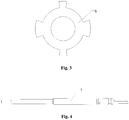
- Figure 3 is a schematic side view showing the structure of a shaft coupling according to an embodiment of the present application
- Figure 4 is a schematic left view showing the structure of a motor shaft according to an embodiment of the present application.
- a motor device includes a motor housing 1, a stator core 2 having at least two poles fixedly installed in the stator housing 1 symmetrically, a coil winding 3 wound around the stator core 2, and an insulating coil holder 4 for insulating the stator core 2 from the coil winding 3.
- the motor device further includes at least two pairs of magnetic steel structures 5 cooperating with the stator core 2, the magnetic steel structures 5 are all fixedly connected to a periphery of a shaft coupling 6, and the shaft coupling 6 is fixedly connected to a motor shaft 7.
- the coil winding 3 is electrified to generate a magnetic field at the stator core 2, the magnetic field drives the magnetic steel structures 5 to drive the shaft coupling 6 to rotate, and in turn the motor shaft 7 is driven to move.
- the movement transmission is realized by the electromagnetic effect, and elastic structures such as a torsion bar is no longer needed.
- the motor can have a greater torque per unit volume, which, on the premise of reaching the rated torque, reduces the size of the motor as much as possible and reduces the weight of the electric toothbrush as much as possible, thereby improving the user experience.
- the motor device transmits power via the electromagnetic structure, hence the power transmission process is more stable, and the range of oscillation of the motor shaft 7 subjecting to different loads will not vary greatly, which facilitates the user to use the electric toothbrush.
- a plastic cement end cap 8 is fixedly connected to one end, opposite to the motor shaft 7, of the motor housing 1, and the outer contour of the plastic cement end cap 8 matches with the inner contour of the motor housing 1.
- one end of the motor housing 1 is closed by the plastic cement end cap 8, which, on the one hand, provides a support position for the internal structures and facilitates the internal structures to be installed compactly and to cooperate with each other stably, and on the other hand, can also protect the internal structures from pollution and influence in the external environment as much as possible, to ensure sustained and stable internal power transmission.
- a pair of ball bearings 9 is connected between the motor shaft 7 and the motor housing 1, and the insulating coil holder 4 has an annular structure for supporting the ball bearings 9.
- the motor shaft 7 is connected to the ball bearings 9, which makes the rotation of the motor shaft 7 smoother, thus avoiding the wear of the motor shaft 7 and stabilizing the position of the motor shaft 7.
- the ball bearings 9 are supported by the annular structure on the insulating coil holder 4. The pair of ball bearings 9 allows a front end and a rear end of the motor shaft 7 to be subjected to forces uniformly, and thus the motor shaft 7 can be installed steadily.
- the insulating coil holder 4 may adopt split type design, a pair of insulating coil holders 4 are respectively inserted into the motor housing 1 from two ends of the motor housing 1, the annular structures may also be provided separately, and each of the insulating coil holders 4 is provided with one annular structure, thus avoids interference between each other and facilitates installation and maintenance.
- an included angle between the each two adjacent magnetic steel structures 5 with respect to the shaft coupling 6 has a preset angle value, and at least two preset angle values are different from each other.
- the magnetic steel structures 5 are unevenly distributed on the periphery of the shaft coupling 6, which allows the motor shaft 7 to vibrate during the rotation process of the magnetic steel structures 5, thereby optimizing the vibration effect of the motor shaft 7 during use, and enhancing the cleaning ability of the electric toothbrush.
- the values of the included angles between the adjacent magnetic steel structures 5 with respect to the shaft coupling 6 may be differ from one another and randomly set, or just two included angles have different values, and specific choices can be made flexibly according to the actual requirements.
- two pairs of magnetic steel structures 5 are fixedly connected to the shaft coupling 6, and the specification of at least one magnetic steel structure 5 is different from the specifications of the other magnetic steel structures 5.
- the magnetic steel structures 5 have different specifications, which is equivalent to the magnetic steel structures 5 having same specifications being installed at different angles, and in this case, the effect of the uneven distribution of the magnetic steel structure 5 on the periphery of the shaft coupling 6 can also be realized, and the same technical effect described above can also be obtained, which will not be described herein.
- the motor shaft 7 includes three sections of stepped structures, and the stepped structures are fixedly connected end to end.
- the motor shaft 7 includes the three sections of stepped structures, which makes the assembling of the motor shaft 7 more convenient and the matching degree between the shape of the motor shaft 7 and other structures better, and more efficiently saves the space.
- the stepped structures facilitate the machining of the motor shaft 7, and reduces the overall manufacturing difficulty of the motor shaft 7.
- an electric toothbrush is provided according to the present application.
- the electric toothbrush includes any one of the motor devices in the above embodiments. Since the electric toothbrush employs the motor devices in the above embodiments, the beneficial effects of the electric toothbrush may refer to the above embodiments.
Landscapes
- Engineering & Computer Science (AREA)
- Power Engineering (AREA)
- Health & Medical Sciences (AREA)
- Dentistry (AREA)
- Epidemiology (AREA)
- Life Sciences & Earth Sciences (AREA)
- Animal Behavior & Ethology (AREA)
- General Health & Medical Sciences (AREA)
- Public Health (AREA)
- Veterinary Medicine (AREA)
- Brushes (AREA)
Applications Claiming Priority (2)
| Application Number | Priority Date | Filing Date | Title |
|---|---|---|---|
| CN201720272757.5U CN206977236U (zh) | 2017-03-20 | 2017-03-20 | 一种电动牙刷及其电机装置 |
| CN201710165611.5A CN106685135A (zh) | 2017-03-20 | 2017-03-20 | 一种电动牙刷及其电机装置 |
Publications (2)
| Publication Number | Publication Date |
|---|---|
| EP3379698A1 true EP3379698A1 (de) | 2018-09-26 |
| EP3379698B1 EP3379698B1 (de) | 2020-02-12 |
Family
ID=60083225
Family Applications (1)
| Application Number | Title | Priority Date | Filing Date |
|---|---|---|---|
| EP17275162.0A Active EP3379698B1 (de) | 2017-03-20 | 2017-10-11 | Elektrische zahnbürste und motorvorrichtung dafür |
Country Status (2)
| Country | Link |
|---|---|
| US (1) | US10695153B2 (de) |
| EP (1) | EP3379698B1 (de) |
Families Citing this family (2)
| Publication number | Priority date | Publication date | Assignee | Title |
|---|---|---|---|---|
| CN110932426A (zh) * | 2019-12-27 | 2020-03-27 | 东莞市米贝科技有限公司 | 一种电机装置及电动牙刷 |
| US11654008B2 (en) | 2020-10-26 | 2023-05-23 | Colgate-Palmolive Company | Personal care system and method |
Citations (7)
| Publication number | Priority date | Publication date | Assignee | Title |
|---|---|---|---|---|
| EP0504093A1 (de) * | 1991-03-15 | 1992-09-16 | Emerson Electric Co. | Geschalteter Reluktanzmotor mit aus isolierten Segmenten bestehendem Rotor |
| US5852334A (en) * | 1995-10-19 | 1998-12-22 | Tridelta Industries, Inc. | Staggered pole switched reluctance motor |
| US6051903A (en) * | 1995-10-19 | 2000-04-18 | Tridelta Industries, Inc. | Switched reluctance motor |
| US6060809A (en) * | 1995-10-19 | 2000-05-09 | Tridelta Industries, Inc. | Staggered pole switched reluctance motor |
| WO2015159215A1 (en) * | 2014-04-16 | 2015-10-22 | Koninklijke Philips N.V. | Multifunction modular motor mount bumper |
| CN205178807U (zh) * | 2015-12-10 | 2016-04-20 | 山东大学 | 一种短端部短磁路分块式开关磁阻电机及其控制电路与系统 |
| DE102016108841A1 (de) * | 2015-05-13 | 2016-11-17 | Makita Corporation | Kraftwerkzeug |
Family Cites Families (5)
| Publication number | Priority date | Publication date | Assignee | Title |
|---|---|---|---|---|
| CA2190147C (en) * | 1994-06-06 | 1999-07-06 | Adam B. Craft | High frequency electric toothbrush |
| JP4400464B2 (ja) * | 2005-01-19 | 2010-01-20 | パナソニック電工株式会社 | 振動・ローリング両用リニアアクチュエータ及びこれを用いた電動歯ブラシ |
| US20080209650A1 (en) * | 2005-05-03 | 2008-09-04 | Ultreo, Inc. | Oral hygiene devices |
| US7732952B1 (en) * | 2006-07-14 | 2010-06-08 | Ultreo, Inc. | Oscillatory motors and devices incorporating them |
| US20090273244A1 (en) * | 2006-11-16 | 2009-11-05 | Ming Luo | Electric Reciprocating Motion Device |
-
2017
- 2017-10-11 EP EP17275162.0A patent/EP3379698B1/de active Active
- 2017-10-12 US US15/730,731 patent/US10695153B2/en not_active Expired - Fee Related
Patent Citations (7)
| Publication number | Priority date | Publication date | Assignee | Title |
|---|---|---|---|---|
| EP0504093A1 (de) * | 1991-03-15 | 1992-09-16 | Emerson Electric Co. | Geschalteter Reluktanzmotor mit aus isolierten Segmenten bestehendem Rotor |
| US5852334A (en) * | 1995-10-19 | 1998-12-22 | Tridelta Industries, Inc. | Staggered pole switched reluctance motor |
| US6051903A (en) * | 1995-10-19 | 2000-04-18 | Tridelta Industries, Inc. | Switched reluctance motor |
| US6060809A (en) * | 1995-10-19 | 2000-05-09 | Tridelta Industries, Inc. | Staggered pole switched reluctance motor |
| WO2015159215A1 (en) * | 2014-04-16 | 2015-10-22 | Koninklijke Philips N.V. | Multifunction modular motor mount bumper |
| DE102016108841A1 (de) * | 2015-05-13 | 2016-11-17 | Makita Corporation | Kraftwerkzeug |
| CN205178807U (zh) * | 2015-12-10 | 2016-04-20 | 山东大学 | 一种短端部短磁路分块式开关磁阻电机及其控制电路与系统 |
Also Published As
| Publication number | Publication date |
|---|---|
| US10695153B2 (en) | 2020-06-30 |
| US20180263743A1 (en) | 2018-09-20 |
| EP3379698B1 (de) | 2020-02-12 |
Similar Documents
| Publication | Publication Date | Title |
|---|---|---|
| WO2021249470A1 (zh) | 一种双向磁悬浮声波电机装置 | |
| CN111585415A (zh) | 一种双向磁悬浮有刷电机装置 | |
| CN107394982B (zh) | 微型直流电机 | |
| CN105006942B (zh) | 一种微型往复式摆动器 | |
| CN212323821U (zh) | 一种双向磁悬浮声波电机装置 | |
| US10695153B2 (en) | Electric toothbrush and motor device thereof | |
| US20220160119A1 (en) | U-shaped electric toothbrush | |
| CN108521178A (zh) | 一种磁场四极定位有限制转角声波振动电机 | |
| CN106685135A (zh) | 一种电动牙刷及其电机装置 | |
| CN217592707U (zh) | 滚刷组件以及清洁机器人 | |
| CN210839091U (zh) | 一种电机装置及电动牙刷 | |
| CN212115113U (zh) | 一种双向磁悬浮有刷电机装置 | |
| CN110601488B (zh) | 一种振动电机及电动牙刷 | |
| CN206977236U (zh) | 一种电动牙刷及其电机装置 | |
| CN115378218A (zh) | 一种径向轴运动机构及电动牙刷 | |
| CN110840322A (zh) | 吸尘器和地刷装置 | |
| CN221151129U (zh) | 一种电动牙刷的电机组件 | |
| CN110932426A (zh) | 一种电机装置及电动牙刷 | |
| CN119051321A (zh) | 一种低转速大功率永磁同步一体机 | |
| CN214480213U (zh) | 一种无刷电机及其电动牙刷 | |
| CN202088151U (zh) | 一种直式微型电动螺丝刀 | |
| US20250017710A1 (en) | Bidirectional magnetic levitation brush motor device | |
| CN107126285B (zh) | 一种电动牙刷 | |
| CN215897412U (zh) | 一种高效声波电机 | |
| CN210898782U (zh) | 一种电机 |
Legal Events
| Date | Code | Title | Description |
|---|---|---|---|
| PUAI | Public reference made under article 153(3) epc to a published international application that has entered the european phase |
Free format text: ORIGINAL CODE: 0009012 |
|
| STAA | Information on the status of an ep patent application or granted ep patent |
Free format text: STATUS: THE APPLICATION HAS BEEN PUBLISHED |
|
| AK | Designated contracting states |
Kind code of ref document: A1 Designated state(s): AL AT BE BG CH CY CZ DE DK EE ES FI FR GB GR HR HU IE IS IT LI LT LU LV MC MK MT NL NO PL PT RO RS SE SI SK SM TR |
|
| AX | Request for extension of the european patent |
Extension state: BA ME |
|
| STAA | Information on the status of an ep patent application or granted ep patent |
Free format text: STATUS: REQUEST FOR EXAMINATION WAS MADE |
|
| 17P | Request for examination filed |
Effective date: 20190326 |
|
| RBV | Designated contracting states (corrected) |
Designated state(s): AL AT BE BG CH CY CZ DE DK EE ES FI FR GB GR HR HU IE IS IT LI LT LU LV MC MK MT NL NO PL PT RO RS SE SI SK SM TR |
|
| GRAP | Despatch of communication of intention to grant a patent |
Free format text: ORIGINAL CODE: EPIDOSNIGR1 |
|
| STAA | Information on the status of an ep patent application or granted ep patent |
Free format text: STATUS: GRANT OF PATENT IS INTENDED |
|
| RIC1 | Information provided on ipc code assigned before grant |
Ipc: H02K 1/30 20060101AFI20190509BHEP Ipc: H02K 19/06 20060101ALI20190509BHEP Ipc: A61C 17/34 20060101ALI20190509BHEP Ipc: H02K 19/10 20060101ALI20190509BHEP Ipc: H02K 1/24 20060101ALN20190509BHEP Ipc: H02K 7/14 20060101ALN20190509BHEP |
|
| INTG | Intention to grant announced |
Effective date: 20190527 |
|
| GRAJ | Information related to disapproval of communication of intention to grant by the applicant or resumption of examination proceedings by the epo deleted |
Free format text: ORIGINAL CODE: EPIDOSDIGR1 |
|
| STAA | Information on the status of an ep patent application or granted ep patent |
Free format text: STATUS: REQUEST FOR EXAMINATION WAS MADE |
|
| GRAP | Despatch of communication of intention to grant a patent |
Free format text: ORIGINAL CODE: EPIDOSNIGR1 |
|
| STAA | Information on the status of an ep patent application or granted ep patent |
Free format text: STATUS: GRANT OF PATENT IS INTENDED |
|
| INTG | Intention to grant announced |
Effective date: 20190823 |
|
| RIC1 | Information provided on ipc code assigned before grant |
Ipc: H02K 19/06 20060101ALI20190814BHEP Ipc: H02K 1/30 20060101AFI20190814BHEP Ipc: A61C 17/34 20060101ALI20190814BHEP Ipc: H02K 1/24 20060101ALN20190814BHEP Ipc: H02K 19/10 20060101ALI20190814BHEP Ipc: H02K 7/14 20060101ALN20190814BHEP |
|
| GRAS | Grant fee paid |
Free format text: ORIGINAL CODE: EPIDOSNIGR3 |
|
| GRAA | (expected) grant |
Free format text: ORIGINAL CODE: 0009210 |
|
| STAA | Information on the status of an ep patent application or granted ep patent |
Free format text: STATUS: THE PATENT HAS BEEN GRANTED |
|
| AK | Designated contracting states |
Kind code of ref document: B1 Designated state(s): AL AT BE BG CH CY CZ DE DK EE ES FI FR GB GR HR HU IE IS IT LI LT LU LV MC MK MT NL NO PL PT RO RS SE SI SK SM TR |
|
| REG | Reference to a national code |
Ref country code: GB Ref legal event code: FG4D |
|
| REG | Reference to a national code |
Ref country code: CH Ref legal event code: EP |
|
| REG | Reference to a national code |
Ref country code: AT Ref legal event code: REF Ref document number: 1233393 Country of ref document: AT Kind code of ref document: T Effective date: 20200215 |
|
| REG | Reference to a national code |
Ref country code: IE Ref legal event code: FG4D |
|
| REG | Reference to a national code |
Ref country code: DE Ref legal event code: R096 Ref document number: 602017011614 Country of ref document: DE |
|
| PG25 | Lapsed in a contracting state [announced via postgrant information from national office to epo] |
Ref country code: FI Free format text: LAPSE BECAUSE OF FAILURE TO SUBMIT A TRANSLATION OF THE DESCRIPTION OR TO PAY THE FEE WITHIN THE PRESCRIBED TIME-LIMIT Effective date: 20200212 Ref country code: RS Free format text: LAPSE BECAUSE OF FAILURE TO SUBMIT A TRANSLATION OF THE DESCRIPTION OR TO PAY THE FEE WITHIN THE PRESCRIBED TIME-LIMIT Effective date: 20200212 Ref country code: NO Free format text: LAPSE BECAUSE OF FAILURE TO SUBMIT A TRANSLATION OF THE DESCRIPTION OR TO PAY THE FEE WITHIN THE PRESCRIBED TIME-LIMIT Effective date: 20200512 |
|
| REG | Reference to a national code |
Ref country code: LT Ref legal event code: MG4D |
|
| REG | Reference to a national code |
Ref country code: NL Ref legal event code: MP Effective date: 20200212 |
|
| PG25 | Lapsed in a contracting state [announced via postgrant information from national office to epo] |
Ref country code: IS Free format text: LAPSE BECAUSE OF FAILURE TO SUBMIT A TRANSLATION OF THE DESCRIPTION OR TO PAY THE FEE WITHIN THE PRESCRIBED TIME-LIMIT Effective date: 20200612 Ref country code: GR Free format text: LAPSE BECAUSE OF FAILURE TO SUBMIT A TRANSLATION OF THE DESCRIPTION OR TO PAY THE FEE WITHIN THE PRESCRIBED TIME-LIMIT Effective date: 20200513 Ref country code: BG Free format text: LAPSE BECAUSE OF FAILURE TO SUBMIT A TRANSLATION OF THE DESCRIPTION OR TO PAY THE FEE WITHIN THE PRESCRIBED TIME-LIMIT Effective date: 20200512 Ref country code: SE Free format text: LAPSE BECAUSE OF FAILURE TO SUBMIT A TRANSLATION OF THE DESCRIPTION OR TO PAY THE FEE WITHIN THE PRESCRIBED TIME-LIMIT Effective date: 20200212 Ref country code: HR Free format text: LAPSE BECAUSE OF FAILURE TO SUBMIT A TRANSLATION OF THE DESCRIPTION OR TO PAY THE FEE WITHIN THE PRESCRIBED TIME-LIMIT Effective date: 20200212 Ref country code: LV Free format text: LAPSE BECAUSE OF FAILURE TO SUBMIT A TRANSLATION OF THE DESCRIPTION OR TO PAY THE FEE WITHIN THE PRESCRIBED TIME-LIMIT Effective date: 20200212 |
|
| PG25 | Lapsed in a contracting state [announced via postgrant information from national office to epo] |
Ref country code: NL Free format text: LAPSE BECAUSE OF FAILURE TO SUBMIT A TRANSLATION OF THE DESCRIPTION OR TO PAY THE FEE WITHIN THE PRESCRIBED TIME-LIMIT Effective date: 20200212 |
|
| PG25 | Lapsed in a contracting state [announced via postgrant information from national office to epo] |
Ref country code: PT Free format text: LAPSE BECAUSE OF FAILURE TO SUBMIT A TRANSLATION OF THE DESCRIPTION OR TO PAY THE FEE WITHIN THE PRESCRIBED TIME-LIMIT Effective date: 20200705 Ref country code: ES Free format text: LAPSE BECAUSE OF FAILURE TO SUBMIT A TRANSLATION OF THE DESCRIPTION OR TO PAY THE FEE WITHIN THE PRESCRIBED TIME-LIMIT Effective date: 20200212 Ref country code: DK Free format text: LAPSE BECAUSE OF FAILURE TO SUBMIT A TRANSLATION OF THE DESCRIPTION OR TO PAY THE FEE WITHIN THE PRESCRIBED TIME-LIMIT Effective date: 20200212 Ref country code: SK Free format text: LAPSE BECAUSE OF FAILURE TO SUBMIT A TRANSLATION OF THE DESCRIPTION OR TO PAY THE FEE WITHIN THE PRESCRIBED TIME-LIMIT Effective date: 20200212 Ref country code: RO Free format text: LAPSE BECAUSE OF FAILURE TO SUBMIT A TRANSLATION OF THE DESCRIPTION OR TO PAY THE FEE WITHIN THE PRESCRIBED TIME-LIMIT Effective date: 20200212 Ref country code: EE Free format text: LAPSE BECAUSE OF FAILURE TO SUBMIT A TRANSLATION OF THE DESCRIPTION OR TO PAY THE FEE WITHIN THE PRESCRIBED TIME-LIMIT Effective date: 20200212 Ref country code: SM Free format text: LAPSE BECAUSE OF FAILURE TO SUBMIT A TRANSLATION OF THE DESCRIPTION OR TO PAY THE FEE WITHIN THE PRESCRIBED TIME-LIMIT Effective date: 20200212 Ref country code: LT Free format text: LAPSE BECAUSE OF FAILURE TO SUBMIT A TRANSLATION OF THE DESCRIPTION OR TO PAY THE FEE WITHIN THE PRESCRIBED TIME-LIMIT Effective date: 20200212 Ref country code: CZ Free format text: LAPSE BECAUSE OF FAILURE TO SUBMIT A TRANSLATION OF THE DESCRIPTION OR TO PAY THE FEE WITHIN THE PRESCRIBED TIME-LIMIT Effective date: 20200212 |
|
| REG | Reference to a national code |
Ref country code: DE Ref legal event code: R097 Ref document number: 602017011614 Country of ref document: DE |
|
| REG | Reference to a national code |
Ref country code: AT Ref legal event code: MK05 Ref document number: 1233393 Country of ref document: AT Kind code of ref document: T Effective date: 20200212 |
|
| PLBE | No opposition filed within time limit |
Free format text: ORIGINAL CODE: 0009261 |
|
| STAA | Information on the status of an ep patent application or granted ep patent |
Free format text: STATUS: NO OPPOSITION FILED WITHIN TIME LIMIT |
|
| 26N | No opposition filed |
Effective date: 20201113 |
|
| PG25 | Lapsed in a contracting state [announced via postgrant information from national office to epo] |
Ref country code: IT Free format text: LAPSE BECAUSE OF FAILURE TO SUBMIT A TRANSLATION OF THE DESCRIPTION OR TO PAY THE FEE WITHIN THE PRESCRIBED TIME-LIMIT Effective date: 20200212 Ref country code: AT Free format text: LAPSE BECAUSE OF FAILURE TO SUBMIT A TRANSLATION OF THE DESCRIPTION OR TO PAY THE FEE WITHIN THE PRESCRIBED TIME-LIMIT Effective date: 20200212 |
|
| PG25 | Lapsed in a contracting state [announced via postgrant information from national office to epo] |
Ref country code: SI Free format text: LAPSE BECAUSE OF FAILURE TO SUBMIT A TRANSLATION OF THE DESCRIPTION OR TO PAY THE FEE WITHIN THE PRESCRIBED TIME-LIMIT Effective date: 20200212 Ref country code: PL Free format text: LAPSE BECAUSE OF FAILURE TO SUBMIT A TRANSLATION OF THE DESCRIPTION OR TO PAY THE FEE WITHIN THE PRESCRIBED TIME-LIMIT Effective date: 20200212 |
|
| REG | Reference to a national code |
Ref country code: CH Ref legal event code: PL |
|
| PG25 | Lapsed in a contracting state [announced via postgrant information from national office to epo] |
Ref country code: LU Free format text: LAPSE BECAUSE OF NON-PAYMENT OF DUE FEES Effective date: 20201011 Ref country code: MC Free format text: LAPSE BECAUSE OF FAILURE TO SUBMIT A TRANSLATION OF THE DESCRIPTION OR TO PAY THE FEE WITHIN THE PRESCRIBED TIME-LIMIT Effective date: 20200212 |
|
| REG | Reference to a national code |
Ref country code: BE Ref legal event code: MM Effective date: 20201031 |
|
| PG25 | Lapsed in a contracting state [announced via postgrant information from national office to epo] |
Ref country code: LI Free format text: LAPSE BECAUSE OF NON-PAYMENT OF DUE FEES Effective date: 20201031 Ref country code: CH Free format text: LAPSE BECAUSE OF NON-PAYMENT OF DUE FEES Effective date: 20201031 Ref country code: BE Free format text: LAPSE BECAUSE OF NON-PAYMENT OF DUE FEES Effective date: 20201031 |
|
| PG25 | Lapsed in a contracting state [announced via postgrant information from national office to epo] |
Ref country code: IE Free format text: LAPSE BECAUSE OF NON-PAYMENT OF DUE FEES Effective date: 20201011 |
|
| PG25 | Lapsed in a contracting state [announced via postgrant information from national office to epo] |
Ref country code: TR Free format text: LAPSE BECAUSE OF FAILURE TO SUBMIT A TRANSLATION OF THE DESCRIPTION OR TO PAY THE FEE WITHIN THE PRESCRIBED TIME-LIMIT Effective date: 20200212 Ref country code: MT Free format text: LAPSE BECAUSE OF FAILURE TO SUBMIT A TRANSLATION OF THE DESCRIPTION OR TO PAY THE FEE WITHIN THE PRESCRIBED TIME-LIMIT Effective date: 20200212 Ref country code: CY Free format text: LAPSE BECAUSE OF FAILURE TO SUBMIT A TRANSLATION OF THE DESCRIPTION OR TO PAY THE FEE WITHIN THE PRESCRIBED TIME-LIMIT Effective date: 20200212 |
|
| PG25 | Lapsed in a contracting state [announced via postgrant information from national office to epo] |
Ref country code: MK Free format text: LAPSE BECAUSE OF FAILURE TO SUBMIT A TRANSLATION OF THE DESCRIPTION OR TO PAY THE FEE WITHIN THE PRESCRIBED TIME-LIMIT Effective date: 20200212 Ref country code: AL Free format text: LAPSE BECAUSE OF FAILURE TO SUBMIT A TRANSLATION OF THE DESCRIPTION OR TO PAY THE FEE WITHIN THE PRESCRIBED TIME-LIMIT Effective date: 20200212 |
|
| PGFP | Annual fee paid to national office [announced via postgrant information from national office to epo] |
Ref country code: FR Payment date: 20221020 Year of fee payment: 6 |
|
| PGFP | Annual fee paid to national office [announced via postgrant information from national office to epo] |
Ref country code: GB Payment date: 20221027 Year of fee payment: 6 Ref country code: DE Payment date: 20221012 Year of fee payment: 6 |
|
| REG | Reference to a national code |
Ref country code: DE Ref legal event code: R119 Ref document number: 602017011614 Country of ref document: DE |
|
| GBPC | Gb: european patent ceased through non-payment of renewal fee |
Effective date: 20231011 |
|
| PG25 | Lapsed in a contracting state [announced via postgrant information from national office to epo] |
Ref country code: GB Free format text: LAPSE BECAUSE OF NON-PAYMENT OF DUE FEES Effective date: 20231011 |
|
| PG25 | Lapsed in a contracting state [announced via postgrant information from national office to epo] |
Ref country code: GB Free format text: LAPSE BECAUSE OF NON-PAYMENT OF DUE FEES Effective date: 20231011 Ref country code: FR Free format text: LAPSE BECAUSE OF NON-PAYMENT OF DUE FEES Effective date: 20231031 Ref country code: DE Free format text: LAPSE BECAUSE OF NON-PAYMENT OF DUE FEES Effective date: 20240501 |