EP3380047B1 - Implant acetabulair - Google Patents
Implant acetabulair Download PDFInfo
- Publication number
- EP3380047B1 EP3380047B1 EP16804722.3A EP16804722A EP3380047B1 EP 3380047 B1 EP3380047 B1 EP 3380047B1 EP 16804722 A EP16804722 A EP 16804722A EP 3380047 B1 EP3380047 B1 EP 3380047B1
- Authority
- EP
- European Patent Office
- Prior art keywords
- outer shell
- toothing
- inner shell
- shell
- toothing system
- Prior art date
- Legal status (The legal status is an assumption and is not a legal conclusion. Google has not performed a legal analysis and makes no representation as to the accuracy of the status listed.)
- Active
Links
Images


Classifications
-
- A—HUMAN NECESSITIES
- A61—MEDICAL OR VETERINARY SCIENCE; HYGIENE
- A61F—FILTERS IMPLANTABLE INTO BLOOD VESSELS; PROSTHESES; DEVICES PROVIDING PATENCY TO, OR PREVENTING COLLAPSING OF, TUBULAR STRUCTURES OF THE BODY, e.g. STENTS; ORTHOPAEDIC, NURSING OR CONTRACEPTIVE DEVICES; FOMENTATION; TREATMENT OR PROTECTION OF EYES OR EARS; BANDAGES, DRESSINGS OR ABSORBENT PADS; FIRST-AID KITS
- A61F2/00—Filters implantable into blood vessels; Prostheses, i.e. artificial substitutes or replacements for parts of the body; Appliances for connecting them with the body; Devices providing patency to, or preventing collapsing of, tubular structures of the body, e.g. stents
- A61F2/02—Prostheses implantable into the body
- A61F2/30—Joints
- A61F2/32—Joints for the hip
- A61F2/34—Acetabular cups
-
- A—HUMAN NECESSITIES
- A61—MEDICAL OR VETERINARY SCIENCE; HYGIENE
- A61F—FILTERS IMPLANTABLE INTO BLOOD VESSELS; PROSTHESES; DEVICES PROVIDING PATENCY TO, OR PREVENTING COLLAPSING OF, TUBULAR STRUCTURES OF THE BODY, e.g. STENTS; ORTHOPAEDIC, NURSING OR CONTRACEPTIVE DEVICES; FOMENTATION; TREATMENT OR PROTECTION OF EYES OR EARS; BANDAGES, DRESSINGS OR ABSORBENT PADS; FIRST-AID KITS
- A61F2/00—Filters implantable into blood vessels; Prostheses, i.e. artificial substitutes or replacements for parts of the body; Appliances for connecting them with the body; Devices providing patency to, or preventing collapsing of, tubular structures of the body, e.g. stents
- A61F2/02—Prostheses implantable into the body
- A61F2/30—Joints
- A61F2002/30001—Additional features of subject-matter classified in A61F2/28, A61F2/30 and subgroups thereof
- A61F2002/30316—The prosthesis having different structural features at different locations within the same prosthesis; Connections between prosthetic parts; Special structural features of bone or joint prostheses not otherwise provided for
- A61F2002/30329—Connections or couplings between prosthetic parts, e.g. between modular parts; Connecting elements
- A61F2002/30331—Connections or couplings between prosthetic parts, e.g. between modular parts; Connecting elements made by longitudinally pushing a protrusion into a complementarily-shaped recess, e.g. held by friction fit
- A61F2002/30332—Conically- or frustoconically-shaped protrusion and recess
-
- A—HUMAN NECESSITIES
- A61—MEDICAL OR VETERINARY SCIENCE; HYGIENE
- A61F—FILTERS IMPLANTABLE INTO BLOOD VESSELS; PROSTHESES; DEVICES PROVIDING PATENCY TO, OR PREVENTING COLLAPSING OF, TUBULAR STRUCTURES OF THE BODY, e.g. STENTS; ORTHOPAEDIC, NURSING OR CONTRACEPTIVE DEVICES; FOMENTATION; TREATMENT OR PROTECTION OF EYES OR EARS; BANDAGES, DRESSINGS OR ABSORBENT PADS; FIRST-AID KITS
- A61F2/00—Filters implantable into blood vessels; Prostheses, i.e. artificial substitutes or replacements for parts of the body; Appliances for connecting them with the body; Devices providing patency to, or preventing collapsing of, tubular structures of the body, e.g. stents
- A61F2/02—Prostheses implantable into the body
- A61F2/30—Joints
- A61F2002/30001—Additional features of subject-matter classified in A61F2/28, A61F2/30 and subgroups thereof
- A61F2002/30316—The prosthesis having different structural features at different locations within the same prosthesis; Connections between prosthetic parts; Special structural features of bone or joint prostheses not otherwise provided for
- A61F2002/30329—Connections or couplings between prosthetic parts, e.g. between modular parts; Connecting elements
- A61F2002/30331—Connections or couplings between prosthetic parts, e.g. between modular parts; Connecting elements made by longitudinally pushing a protrusion into a complementarily-shaped recess, e.g. held by friction fit
- A61F2002/30362—Connections or couplings between prosthetic parts, e.g. between modular parts; Connecting elements made by longitudinally pushing a protrusion into a complementarily-shaped recess, e.g. held by friction fit with possibility of relative movement between the protrusion and the recess
- A61F2002/30364—Rotation about the common longitudinal axis
- A61F2002/30367—Rotation about the common longitudinal axis with additional means for preventing said rotation
-
- A—HUMAN NECESSITIES
- A61—MEDICAL OR VETERINARY SCIENCE; HYGIENE
- A61F—FILTERS IMPLANTABLE INTO BLOOD VESSELS; PROSTHESES; DEVICES PROVIDING PATENCY TO, OR PREVENTING COLLAPSING OF, TUBULAR STRUCTURES OF THE BODY, e.g. STENTS; ORTHOPAEDIC, NURSING OR CONTRACEPTIVE DEVICES; FOMENTATION; TREATMENT OR PROTECTION OF EYES OR EARS; BANDAGES, DRESSINGS OR ABSORBENT PADS; FIRST-AID KITS
- A61F2/00—Filters implantable into blood vessels; Prostheses, i.e. artificial substitutes or replacements for parts of the body; Appliances for connecting them with the body; Devices providing patency to, or preventing collapsing of, tubular structures of the body, e.g. stents
- A61F2/02—Prostheses implantable into the body
- A61F2/30—Joints
- A61F2002/30001—Additional features of subject-matter classified in A61F2/28, A61F2/30 and subgroups thereof
- A61F2002/30316—The prosthesis having different structural features at different locations within the same prosthesis; Connections between prosthetic parts; Special structural features of bone or joint prostheses not otherwise provided for
- A61F2002/30329—Connections or couplings between prosthetic parts, e.g. between modular parts; Connecting elements
- A61F2002/30476—Connections or couplings between prosthetic parts, e.g. between modular parts; Connecting elements locked by an additional locking mechanism
- A61F2002/30485—Connections or couplings between prosthetic parts, e.g. between modular parts; Connecting elements locked by an additional locking mechanism plastically deformable
-
- A—HUMAN NECESSITIES
- A61—MEDICAL OR VETERINARY SCIENCE; HYGIENE
- A61F—FILTERS IMPLANTABLE INTO BLOOD VESSELS; PROSTHESES; DEVICES PROVIDING PATENCY TO, OR PREVENTING COLLAPSING OF, TUBULAR STRUCTURES OF THE BODY, e.g. STENTS; ORTHOPAEDIC, NURSING OR CONTRACEPTIVE DEVICES; FOMENTATION; TREATMENT OR PROTECTION OF EYES OR EARS; BANDAGES, DRESSINGS OR ABSORBENT PADS; FIRST-AID KITS
- A61F2/00—Filters implantable into blood vessels; Prostheses, i.e. artificial substitutes or replacements for parts of the body; Appliances for connecting them with the body; Devices providing patency to, or preventing collapsing of, tubular structures of the body, e.g. stents
- A61F2/02—Prostheses implantable into the body
- A61F2/30—Joints
- A61F2002/30001—Additional features of subject-matter classified in A61F2/28, A61F2/30 and subgroups thereof
- A61F2002/30316—The prosthesis having different structural features at different locations within the same prosthesis; Connections between prosthetic parts; Special structural features of bone or joint prostheses not otherwise provided for
- A61F2002/30329—Connections or couplings between prosthetic parts, e.g. between modular parts; Connecting elements
- A61F2002/30476—Connections or couplings between prosthetic parts, e.g. between modular parts; Connecting elements locked by an additional locking mechanism
- A61F2002/305—Snap connection
Definitions
- the present invention relates to an acetabular implant, in particular an acetabular implant, comprising an outer shell and an inner shell.
- acetabular cups are often constructed in two parts, namely an outer shell and an inner shell.
- the outer shell is used to embed the socket in the bone.
- the inner shell which is inserted into the outer shell, forms a bearing surface for a corresponding joint head.
- outer shells are often made of a metal, both ceramic materials and plastics, in particular polyethylene, but also suitable metals are used as materials for inner shells.
- Ceramic or metallic inner shells are usually conical, which means that after they have been inserted into an outer shell, they exert a sufficiently large holding force against the torque transmitted by a head of the joint.
- Inner shells made of a plastic material must be additionally secured against twisting.
- Many outer shells therefore have an anti-rotation device in the form of cutouts in their edge area (so-called "scallops"), which are engaged by convex structures of the inner shell.
- recallops an anti-rotation device in the form of cutouts in their edge area
- outer shells have therefore been developed, on the concave inside of which are arranged spike-shaped penetration elements which, when an inner shell made of plastic is inserted, drill into the latter and thus secure against twisting.
- the EP 0 663 193 B1 a revision cup for an artificial hip joint.
- the said pan comprises a hemispherical support shell and a correspondingly dimensioned inner shell.
- the concave inside of the support shell is provided with penetration elements which penetrate into the outer surface of the inner shell when it is inserted in order to prevent twisting.
- the US 5,800,555 a bearing body for a ball joint prosthesis. This bearing body is inserted into an outer shell, which has advances on the inside to prevent rotation. For this purpose, the advances penetrate into the outer surface of the bearing body.
- Such anti-rotation devices have the advantage that no structural measures are necessary on the inner shell to implement them.
- significant costs are incurred in the manufacture of the outer shell by attaching the penetration elements.
- the penetration elements Often the penetration elements cannot be made in one piece with the shell, which means drilling holes and setting and pressing in the elements. If the penetration elements are made of a different material than the outer shell, a declaration of the same is necessary when the product is approved, which makes this even more difficult.
- mandrel-shaped penetration elements In order to enable the inner shell to be inserted into the outer shell, mandrel-shaped penetration elements must also be attached to the bottom of the outer shell, as a result of which they are relatively close to the longitudinal central axis of the outer shell and can therefore transmit only a small torque to the inner shell.
- an implantable cup for hip joint endoprostheses has become known, in which the bearing shell can be inserted into the inner receptacle of the cup in any rotational position and is fixed in a rotationally secure manner.
- a circular multiple toothing is provided on the inner circumference of the receptacle, which engages in the bearing shell to prevent rotation.
- a disadvantage of the previously known rotation inhibition by toothing is that high press-in forces are required to insert the inner shell and that there is a risk that the material of the inner shell is damaged, with undesired machining taking place, in which particles of the inner shell may be removed.
- the teeth have an unfavorable configuration or they are oversized or too numerous to withstand a predetermined target torque between the two shell parts. It should also be taken into account that the press-in force required to insert the inner shell is limited, when the surgeon has to drive in or press in the inner shell.
- an object of the present invention to overcome the above-mentioned disadvantages in the prior art.
- Such an anti-rotation device should be easy to implement in existing implant systems.
- their implementation should be inexpensive and allow the treating surgeon easy handling of the implant and a continuous axial angle adjustment with respect to the shell axis.
- a further object of the present invention is to design the toothing in such a way that the softer material of the inner shell is not damaged and that a maximum torque can be transmitted with the lowest possible press-in force.
- This joint socket implant comprises an outer shell with a convex outer side and a concave inner side, the latter of which has teeth in a circular circumferential area.
- the flanks of the toothing are aligned parallel to the longitudinal center axis of the outer shell and the tooth profile has a tooth height which is defined as the difference between the radius of the tip circle and the radius of the root circle of the toothing.
- the socket implant further comprises an inner shell inserted into the outer shell, the hardness of the outer shell being greater than that of the inner shell and the area of the inner shell coming into contact with the toothing having an excess relative to the tip circle of the toothing. This is an inhibition of relative rotational ability of the two shells can be achieved by displacing the material of the inner shell through the teeth.
- the toothing extends continuously, preferably with a uniform division, over the circular area on the outer shell.
- Uniform pitch is understood to mean an equal distance between the individual teeth, in such a way that the toothing corresponds to an internal toothing that extends over 360 °.
- the outer shell and the inner shell advantageously have corresponding axial latching elements, on which they are latched together with respect to the common longitudinal central axis.
- Such latching is necessary because with an inner shell made of plastic material, no self-locking can be achieved in the axial direction, for example by a cone connection.
- the circumferential region with the toothing is particularly advantageously arranged in a cylindrical section of the concave inside of the outer shell, which connects to the corresponding latching elements with respect to the common longitudinal central axis.
- Production-related advantages can be achieved through the immediate vicinity of the locking elements to the toothing. It does not matter whether the toothing or the locking elements are arranged first with respect to the common longitudinal central axis from the equator of the shell to the apex. In principle, it would also be possible to arrange the toothing and the latching elements in the outer shell at a distance from one another in relation to the common longitudinal central axis.
- the circumferential area with the toothing is closer to the equator of the outer shell with respect to the longitudinal central axis than to the apex of the latter.
- the inside diameter of the outer shell is the largest, which means that a maximum diameter of the toothing can also be achieved. This allows both the number of teeth to be increased and the distance between the teeth and the axis of rotation to be increased, thereby transmitting the greatest possible torque.
- the toothing has a width between 0.5 mm and 5 mm, preferably between 0.8 mm and 1.6 mm, based on the longitudinal central axis.
- the torque that can be transmitted can be determined with the width of the toothing, depending on its depth of penetration into the inner shell. The wider the toothing and thus the maximum possible engagement in relation to the longitudinal center axis, the higher the torque that can be transmitted to the toothing.
- the toothing penetrates into the material of the inner shell with a tooth penetration depth which is between 0.1 mm and 1 mm, preferably between 0.15 mm and 0.3 mm.
- the press-in force is essentially determined by the tooth penetration depth and only insignificantly by the tooth width mentioned above. The greater the depth of penetration, and the more teeth the teeth have, the higher the press-in force required.
- the depth of penetration should be as small as possible so that there is no damage or bracing to the material of the inner shell. This leads to the teaching that the number of teeth must be as large as possible and their penetration depth must be kept as small as possible so that the press-in force can be kept low.
- the transferable torque can then be defined using the tooth width.
- the total number of teeth of the toothing and the width of the teeth are selected in relation to the longitudinal central axis in such a way that the inhibition of the ability to rotate always exceeds a predetermined target torque.
- the minimum torque that can be transmitted is specified by the relevant medical standards and must always be observed. With a given penetration depth between 0.1 mm and 1 mm and depending on the shell size or the diameter of the toothing, the number of teeth and their width can be optimized.
- the individual teeth of the toothing can enclose an angle of preferably 45 ° to 100 °. For manufacturing reasons, there will always be a slight flattening or rounding at the top. An angle of more than 100 ° leads to correspondingly wide teeth on the tooth base, which reduces the total number of teeth that can be accommodated in the surrounding area.
- the toothing can also only partially extend over the circular circumferential area.
- a toothing that is partially interrupted in this way has the advantage that the press-in force can be reduced and that with a constant penetration depth.
- the inner shell particularly advantageously consists of a plastic material, in particular a polyethylene with a Shore hardness D between 50 and 85.
- a plastic material with this hardness has optimal material properties so that the inner shell can be pressed into the toothing without being destroyed.
- a torque of more than 10 Nm (Newton meters), preferably of more than 12 Nm, can preferably be transmitted by means of the toothing. This is the target torque mentioned above, which is specified by relevant medical standards. For example, through the "Guidance document for testing acetabular cup prostheses" of the US Federal Drug Administration (FDA). The values given contain a safety factor in relation to the torques actually occurring under load that can be triggered by a patient.
- FDA Federal Drug Administration
- the outer shell for the acetabular implant in particular for an acetabular implant, has a convex outside and a concave inside for receiving an inner shell.
- the concave inside has, at least in part, a toothing in a particularly circular area.
- the teeth can be used to inhibit the relative rotation ability of the two shells with respect to the common main axis when inserting the inner shell into the outer shell.
- teeth on the concave inside of the outer shell creates a particularly reliable anti-twist device.
- the teeth can be easily attached to the outer shell and can be adapted to the respective requirements.
- the toothing is preferably produced by a machining process such as milling or shaping. In certain cases, however, production by a forming process or by eroding is also conceivable.
- the toothing can extend continuously over the area, which in particular is circular. As a result, a comparatively high torque can be transferred from the outer shell to the inner shell. However, a comparatively high press-in force is also required to insert the inner shell into the outer shell. Therefore, the toothing can also extend with interruptions over the particularly circular area. This enables a reduction in the press-in force required to insert the inner shell into the outer shell, but this is at the expense of the transmissible torque. Thanks to a well-coordinated relationship between the areas with toothing and the interruptions, the anti-rotation device can be designed in such a way that an acceptable torque can be transferred from the outer shell to the inner shell with minimal insertion force.
- the radius of the root circle of the toothing can be at least 50%, preferably at least 60%, preferably at least 70% of the total radius of the outer shell. The closer the radius of the root circle to the total radius of the outer shell, the greater the torque that can be transmitted. Under foot circle the circle is understood on which the lowest points of the toothing lie.
- the outer shell can have at least one latching element for axially latching the inner shell in the outer shell.
- snap connections are also spoken in technical jargon.
- Such a snap connection makes it possible, particularly in the case of joint socket implants with inner shells made of plastic, that the inner shell snaps or snaps into the outer shell when it is inserted and is thereby held in place.
- a combination of such a snap connection with an anti-twist device according to the invention makes it possible to anchor an inner shell in the outer shell in such a way that it is secured both against twisting and against falling out.
- the particularly circular area with the toothing can then be arranged on an axial locking element of the outer shell.
- the combination of locking element and toothing can be used to create a compact structural element on the concave inside of the outer shell, which simultaneously secures the inner shell against twisting and falling out.
- the toothing can have a tooth profile with a height which is at least 1.5 to 2 times the desired depth of penetration. This ratio ensures that the material of the inner shell displaced during the press-in process can be accommodated and therefore does not lead to an increase in the press-in force.
- the tooth profile of the toothing can be triangular or trapezoidal and include an angle ⁇ of 30 ° to 120 °, preferably 45 ° to 110 °, preferably 60 ° to 100 °.
- Such Geometries can be easily attached to the concave inside of the outer shell. They have a favorable characteristic when the teeth penetrate into the outside of the inner shell.
- such a tooth profile generally prevents a relative rotational movement between the insert and the outer shell in a particularly reliable manner.
- flanks of the toothing can be aligned parallel to the longitudinal center axis of the outer shell. This configuration enables the region of the inner shell that comes into contact with the toothing to be cylindrical.
- the toothing can have a width of 10 mm to 0.1 mm, preferably 5 mm to 0.5 mm, preferably 1.6 mm to 0.8 mm, based on the axial direction.
- the circumferential area with the toothing can be arranged in a cylindrical section of the concave inside of the outer shell, which adjoins a conical section.
- such outer shells are suitable both as an initial replacement for a ball joint and as revision shells.
- the present invention relates to an acetabular implant comprising an outer shell of the type described above and an inner shell which can be inserted into the outer shell.
- the hardness of the outer shell is greater than that of the inner shell. This is when inserting the inner shell into the outer shell an inhibition of the relative rotational ability of the two shells can be achieved by displacing the material of the inner shell by the teeth of the outer shell.
- the outer shell can be made from titanium or from a titanium, steel, cobalt or zirconium-based alloy.
- the outer shell can also be made from a ceramic material. These materials are common materials used in implant manufacture. They are characterized by excellent biocompatibility and enable the outer shell to be reliably anchored in a patient's bone.
- the inner shell can be made from polyethylene, in particular from a UHMWPE, or from a UXPE, a PEEK or a PEAK.
- UHMWPE is understood to mean an ultra-high molecular weight polyethylene.
- the materials mentioned are common materials for the production of treads in artificial joints. They are characterized by a particularly low sliding resistance, a long service life and good patient tolerance.
- the inner shell is a composite structure consisting of one of the above-mentioned plastic materials and a metal or a ceramic material.
- the convex outer side of the inner shell facing the outer shell is made of a plastic material, while the bearing surface of the joint is made of metal or a ceramic material.
- Composite structures of this type can be pressed into an outer shell according to the invention and, compared to a pure plastic inner shell, have better sliding and abrasion behavior of the bearing surface.
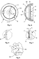
- Figure 1 an outer shell 1 for an acetabular implant 2 ( Fig. 9 ) a convex outside 3 and a concave inside 4.
- the inside 4 has a circular peripheral area 6, which is provided with a toothing 7.
- an inner shell 5 for an inventive acetabular implant 2 has an articulated bearing surface 19 on its concave inside.
- the convex outside 15 is divided into different sections.
- the inner shell 5 shown has a conical region 16, on the edge region near the pole of which a latching element 17 is arranged.
- An extension 18 is attached to the pole of the inner shell 5. Both the conical region 16 and the extension 18 serve to prevent the inner shell 5 from tilting in the outer shell 1.
- the toothing 7 is mounted relatively far outside on the concave inside 4 of the outer shell 1.
- the radius r of the root circle 12 of the toothing 7 here is approximately 70% of the total radius R of the outer shell 1.
- FIG 5 is a schematic representation of the tooth profile according to Figure 4 .
- the root circle 12 and the tip circle 14 are shown in dashed lines in the tooth profile.
- the angle ⁇ enclosed by the tooth profile is also shown.
- the height h of the tooth profile is defined as the difference between the radius of the tip circle 14 and that of the root circle 12.
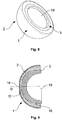
- Out Figure 7 is the design of the locking element 8 provided with a toothing 7. It can be seen that the toothing 7 has the width b, which in the present exemplary embodiment is identical to that of the latching element. It can also be seen that the toothing 7 here has a trapezoidal cross profile.
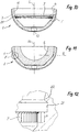
- FIG 8 An inventive acetabular implant 2 with outer shell 1 and inner shell 5 is shown in perspective.
- the joint bearing surface 19 can be seen in particular on the concave inside.
- Figure 9 shows a longitudinal section through said acetabular implant 2. It can be seen that the extension 18 at the pole of the inner shell 5 engages in the opening 13 provided in the outer shell 1.
- the common main axis (longitudinal central axis) of the outer shell and inner shell is designated SS.
- FIGs 10 and 11 show a modified embodiment of an acetabular implant, in which the outer shell has a different inner contour.
- the toothing 7 is arranged in another area.
- the conical inlet area 11 on the inside 4 is followed by a likewise conical undercut 21, the configuration of which is shown in FIG Figure 12 is more clearly visible.
- the shoulder 22 between the undercut 21 and the conical area 11 forms the locking element of the outer shell, behind which a corresponding material shoulder 23 of the inner shell engages ( Figure 13 ).
- a circumferential cylindrical region to which the toothing 7 is attached. The toothing extends over the width b and thus not over the entire cylindrical area.
- the penetration depth e should not exceed 0.1 mm to 1 mm.
- the aim is to have the largest possible number of teeth 25 with a uniform spacing a from one another. These teeth have a height h, a difference remaining between e and h, so that a cavity 24 remains between adjacent tooth flanks 9.
- b is the width of the toothing, or more precisely the width of the penetration of the individual teeth into the material of the inner shell 5.
- the transmissible torque increases the greater the width b of the toothing for a given depth of penetration e.
- the press-in force is essentially determined by the penetration depth e.
- a torque specified by medical standards of, for example, greater than 12 Nm, which the inner shell must be able to transmit to the outer shell, the necessary dimensions of the toothing are determined depending on different shell sizes.
Landscapes
- Health & Medical Sciences (AREA)
- Orthopedic Medicine & Surgery (AREA)
- Cardiology (AREA)
- Oral & Maxillofacial Surgery (AREA)
- Transplantation (AREA)
- Engineering & Computer Science (AREA)
- Biomedical Technology (AREA)
- Heart & Thoracic Surgery (AREA)
- Vascular Medicine (AREA)
- Life Sciences & Earth Sciences (AREA)
- Animal Behavior & Ethology (AREA)
- General Health & Medical Sciences (AREA)
- Public Health (AREA)
- Veterinary Medicine (AREA)
- Prostheses (AREA)
Claims (11)
- Implant cotyloïdien (2), en particulier implant cotyloïdien de la hanche, comportant une coque extérieure (1) dotée d'un côté extérieur convexe (3) et d'un côté intérieur concave (4), lequel comprend une denture (7) dans une région périphérique circulaire (6), dans lequel les flancs (9) de la denture sont orientés parallèlement à un axe médian longitudinal (S) de la coque extérieure (1) et dans lequel le profil de dent présente une hauteur de dent (h), laquelle est définie comme la différence entre le rayon du cercle de tête et le rayon du cercle de pied de la denture, et une coque intérieure (5) insérée dans la coque extérieure, dans lequel la dureté de la coque extérieure est supérieure à celle de la coque intérieure et dans lequel la région de la coque intérieure venant en contact avec la denture présente une surmesure par rapport au cercle de tête de la denture, de sorte qu'un blocage de l'aptitude à la rotation relative des deux coques peut être obtenu par déplacement de la matière de la coque intérieure par la denture, caractérisé en ce que la denture (7) s'étend de manière continue avec un pas uniforme sur la région périphérique circulaire (6), de sorte que la denture (7) correspond à une denture intérieure s'étendant sur 360°, la denture (7) pénétrant dans la matière de la coque intérieure (5) sur une profondeur de pénétration de dent (e), laquelle est comprise entre 0,1 et 1,0 mm, une cavité (24) demeurant entre les flancs latéraux de dents adjacentes et la coque intérieure (5) insérée dans la denture (7), et le nombre total de dents de la denture (7) et la largeur (b) des dents par rapport à l'axe médian longitudinal (S) étant sélectionnés de telle sorte que le blocage de l'aptitude à la rotation dépasse un couple de consigne prédéfini de 10 Nm.
- Implant cotyloïdien selon la revendication 1, dans lequel la coque extérieure (1) est fabriquée à partir de titane ou à partir d'un alliage à base de titane, d'acier, de cobalt ou de zircon.
- Implant cotyloïdien selon la revendication 1 ou 2, dans lequel la coque intérieure (5) est fabriquée à partir d'un polyéthylène, en particulier à partir d'un UHMWPE ou à partir d'un UXPE, ou à partir d'un PEEK ou à partir d'un PEAK.
- Implant cotyloïdien selon l'une des revendications 1 à 3, dans lequel la coque extérieure (1) et la coque intérieure (5) comprennent des éléments d'encliquetage axiaux (8, 17) correspondants, au niveau desquels elles sont encliquetées l'une avec l'autre par rapport à l'axe médian longitudinal commun (S).
- Implant cotyloïdien selon la revendication 4, dans lequel la région périphérique dotée de la denture est disposée dans une partie cylindrique du côté intérieur concave (4) de la coque extérieure (1), qui se raccorde aux éléments d'encliquetage (8, 17) correspondants par rapport à l'axe médian longitudinal commun (S).
- Implant cotyloïdien selon l'une des revendications 1 à 5, dans lequel la profondeur de pénétration de dent (e) est comprise entre 0,15 mm et 0,3 mm.
- Implant cotyloïdien selon l'une des revendications 1 à 6, dans lequel les dents individuelles de la denture forment un angle de préférence de 45° à 100°.
- Implant cotyloïdien selon la revendication 7, dans lequel les flancs latéraux (9) des dents sont des surfaces planes.
- Implant cotyloïdien selon l'une des revendications 1 à 8, dans lequel la région périphérique dotée de la denture (7) est située, par rapport à l'axe médian longitudinal (S), plus près de l'équateur de la coque extérieure (1) que de son sommet.
- Implant cotyloïdien selon l'une des revendications 1 à 9, dans lequel la coque intérieure (5) est constituée d'une matière synthétique, en particulier d'un polyéthylène, présentant une dureté Shore D comprise entre 50 et 85.
- Implant cotyloïdien selon l'une des revendications 1 à 10, dans lequel un couple supérieur à 12 Nm peut être transmis au moyen de la denture.
Applications Claiming Priority (2)
| Application Number | Priority Date | Filing Date | Title |
|---|---|---|---|
| EP15195856 | 2015-11-23 | ||
| PCT/EP2016/078390 WO2017089332A1 (fr) | 2015-11-23 | 2016-11-22 | Implant de cavité cotyloïde |
Publications (2)
| Publication Number | Publication Date |
|---|---|
| EP3380047A1 EP3380047A1 (fr) | 2018-10-03 |
| EP3380047B1 true EP3380047B1 (fr) | 2020-07-08 |
Family
ID=54697489
Family Applications (1)
| Application Number | Title | Priority Date | Filing Date |
|---|---|---|---|
| EP16804722.3A Active EP3380047B1 (fr) | 2015-11-23 | 2016-11-22 | Implant acetabulair |
Country Status (4)
| Country | Link |
|---|---|
| US (1) | US10945849B2 (fr) |
| EP (1) | EP3380047B1 (fr) |
| CN (1) | CN108289740A (fr) |
| WO (1) | WO2017089332A1 (fr) |
Families Citing this family (1)
| Publication number | Priority date | Publication date | Assignee | Title |
|---|---|---|---|---|
| CN113749827B (zh) * | 2021-11-05 | 2022-04-19 | 北京爱康宜诚医疗器材有限公司 | 髋臼假体 |
Family Cites Families (8)
| Publication number | Priority date | Publication date | Assignee | Title |
|---|---|---|---|---|
| US5092897A (en) * | 1990-03-15 | 1992-03-03 | Forte Mark R | Implantable acetabular prosthetic hip joint with universal adjustability |
| EP0663193B1 (fr) | 1993-12-20 | 2000-02-02 | Sulzer Orthopädie AG | Coque acétabulaire artificielle pour la hanche |
| US5800555A (en) * | 1997-04-24 | 1998-09-01 | Depuy Orthopaedics, Inc. | Acetabular cup bearing liner |
| DE10106863C2 (de) | 2001-02-14 | 2003-04-03 | Hans Ulrich Staeubli | Implantierbare Pfanne für Hüftgelenk-Endoprothesen |
| EP1420724A1 (fr) * | 2001-08-20 | 2004-05-26 | Biomet Merck GmbH | Acetabulum artificiel |
| FR2829687B1 (fr) * | 2001-09-20 | 2003-12-05 | Smile Fit | Cotyle prothetique de la hanche |
| DE102006017473A1 (de) * | 2006-04-13 | 2007-10-18 | Plus Orthopedics Ag | Gelenkpfanne, insbesondere für eine Hüftendoprothese |
| FR2936145B1 (fr) * | 2008-09-25 | 2011-11-11 | Sem Sa | Cotyle pour prothese articulaire de hanche a impacter dans la cavite cotyloidienne de l'os iliaque d'un patient |
-
2016
- 2016-11-22 WO PCT/EP2016/078390 patent/WO2017089332A1/fr not_active Ceased
- 2016-11-22 CN CN201680067939.7A patent/CN108289740A/zh active Pending
- 2016-11-22 EP EP16804722.3A patent/EP3380047B1/fr active Active
- 2016-11-22 US US15/776,492 patent/US10945849B2/en active Active
Non-Patent Citations (1)
| Title |
|---|
| None * |
Also Published As
| Publication number | Publication date |
|---|---|
| WO2017089332A1 (fr) | 2017-06-01 |
| CN108289740A (zh) | 2018-07-17 |
| EP3380047A1 (fr) | 2018-10-03 |
| US10945849B2 (en) | 2021-03-16 |
| US20180325678A1 (en) | 2018-11-15 |
Similar Documents
| Publication | Publication Date | Title |
|---|---|---|
| EP2688517B1 (fr) | Implant à coque acétabulaire | |
| DE69432717T2 (de) | Gelenkpfanne | |
| EP0795306B1 (fr) | Prothèse osseuse modulaire comportant une cupule et des pointes | |
| AT390183B (de) | Knochenimplantat fuer endoprothesen | |
| DE69823968T2 (de) | Verfahren zur Herstellung eines kaltgehärteten Verbinders für modulare Teile | |
| EP0388745A1 (fr) | Cuvette d'articulation de la hanche pour l'implantation sans ciment dans la cavité acétabulaire | |
| EP0601224B1 (fr) | Coquille de fixation pour recevoir la coupole d'une coupole de hanche synthétique | |
| EP0318679B2 (fr) | Endoprothèse pour un cotyle de hanche | |
| EP0024442A1 (fr) | Endoprothèse composée consistant en un corps métallique et une articulation en céramique | |
| WO2005079709A1 (fr) | Prothese pour un remplacement en surface dans la zone de la sphere d'une enarthrose | |
| EP0578345B1 (fr) | Endoprothèse de coque acétabulaire | |
| DE10106863C2 (de) | Implantierbare Pfanne für Hüftgelenk-Endoprothesen | |
| EP1411869B1 (fr) | Prothese d'articulation artificiel | |
| EP3380047B1 (fr) | Implant acetabulair | |
| EP3493771B1 (fr) | Cuvette acétabulaire et endoprothèse d'articulation | |
| WO1996022746A1 (fr) | Implant osseux modulaire a cavite glenoïde et broches | |
| EP4231946B1 (fr) | Élément fileté optimisé pour l'impression 3d | |
| EP2338443B1 (fr) | Cotyle d'articulation de la hanche artificielle destinée à l'ancrage non cimenté | |
| DE4310592A1 (de) | Künstliche Hüftgelenkspfanne | |
| EP4147678B1 (fr) | Dispositif d'augmentation et système d'augmentation | |
| DE102005038038A1 (de) | Werkzeuge zum Herstellen und Vorbereiten einer Bohrung zur Aufnahme von Zahnimplantaten und entsprechendes Zahnimplantat | |
| DE602006000956T2 (de) | Prothese mit selbststanzenden Erhöhungen | |
| DE10029637C2 (de) | Endoprothesensystem | |
| CH703012A1 (de) | Dentalimplantat. | |
| EP0775475A2 (fr) | Coque en forme de coquille pour une prothèse de l'articulation de la hanche |
Legal Events
| Date | Code | Title | Description |
|---|---|---|---|
| STAA | Information on the status of an ep patent application or granted ep patent |
Free format text: STATUS: UNKNOWN |
|
| STAA | Information on the status of an ep patent application or granted ep patent |
Free format text: STATUS: THE INTERNATIONAL PUBLICATION HAS BEEN MADE |
|
| PUAI | Public reference made under article 153(3) epc to a published international application that has entered the european phase |
Free format text: ORIGINAL CODE: 0009012 |
|
| STAA | Information on the status of an ep patent application or granted ep patent |
Free format text: STATUS: REQUEST FOR EXAMINATION WAS MADE |
|
| 17P | Request for examination filed |
Effective date: 20180507 |
|
| AK | Designated contracting states |
Kind code of ref document: A1 Designated state(s): AL AT BE BG CH CY CZ DE DK EE ES FI FR GB GR HR HU IE IS IT LI LT LU LV MC MK MT NL NO PL PT RO RS SE SI SK SM TR |
|
| AX | Request for extension of the european patent |
Extension state: BA ME |
|
| DAV | Request for validation of the european patent (deleted) | ||
| DAX | Request for extension of the european patent (deleted) | ||
| STAA | Information on the status of an ep patent application or granted ep patent |
Free format text: STATUS: EXAMINATION IS IN PROGRESS |
|
| 17Q | First examination report despatched |
Effective date: 20190726 |
|
| GRAP | Despatch of communication of intention to grant a patent |
Free format text: ORIGINAL CODE: EPIDOSNIGR1 |
|
| STAA | Information on the status of an ep patent application or granted ep patent |
Free format text: STATUS: GRANT OF PATENT IS INTENDED |
|
| INTG | Intention to grant announced |
Effective date: 20200417 |
|
| GRAS | Grant fee paid |
Free format text: ORIGINAL CODE: EPIDOSNIGR3 |
|
| GRAA | (expected) grant |
Free format text: ORIGINAL CODE: 0009210 |
|
| STAA | Information on the status of an ep patent application or granted ep patent |
Free format text: STATUS: THE PATENT HAS BEEN GRANTED |
|
| AK | Designated contracting states |
Kind code of ref document: B1 Designated state(s): AL AT BE BG CH CY CZ DE DK EE ES FI FR GB GR HR HU IE IS IT LI LT LU LV MC MK MT NL NO PL PT RO RS SE SI SK SM TR |
|
| REG | Reference to a national code |
Ref country code: CH Ref legal event code: EP Ref country code: CH Ref legal event code: NV Representative=s name: HEPP WENGER RYFFEL AG, CH Ref country code: AT Ref legal event code: REF Ref document number: 1287648 Country of ref document: AT Kind code of ref document: T Effective date: 20200715 |
|
| REG | Reference to a national code |
Ref country code: DE Ref legal event code: R096 Ref document number: 502016010469 Country of ref document: DE |
|
| REG | Reference to a national code |
Ref country code: IE Ref legal event code: FG4D Free format text: LANGUAGE OF EP DOCUMENT: GERMAN |
|
| REG | Reference to a national code |
Ref country code: LT Ref legal event code: MG4D |
|
| REG | Reference to a national code |
Ref country code: NL Ref legal event code: MP Effective date: 20200708 |
|
| PG25 | Lapsed in a contracting state [announced via postgrant information from national office to epo] |
Ref country code: ES Free format text: LAPSE BECAUSE OF FAILURE TO SUBMIT A TRANSLATION OF THE DESCRIPTION OR TO PAY THE FEE WITHIN THE PRESCRIBED TIME-LIMIT Effective date: 20200708 Ref country code: BG Free format text: LAPSE BECAUSE OF FAILURE TO SUBMIT A TRANSLATION OF THE DESCRIPTION OR TO PAY THE FEE WITHIN THE PRESCRIBED TIME-LIMIT Effective date: 20201008 Ref country code: SE Free format text: LAPSE BECAUSE OF FAILURE TO SUBMIT A TRANSLATION OF THE DESCRIPTION OR TO PAY THE FEE WITHIN THE PRESCRIBED TIME-LIMIT Effective date: 20200708 Ref country code: HR Free format text: LAPSE BECAUSE OF FAILURE TO SUBMIT A TRANSLATION OF THE DESCRIPTION OR TO PAY THE FEE WITHIN THE PRESCRIBED TIME-LIMIT Effective date: 20200708 Ref country code: LT Free format text: LAPSE BECAUSE OF FAILURE TO SUBMIT A TRANSLATION OF THE DESCRIPTION OR TO PAY THE FEE WITHIN THE PRESCRIBED TIME-LIMIT Effective date: 20200708 Ref country code: FI Free format text: LAPSE BECAUSE OF FAILURE TO SUBMIT A TRANSLATION OF THE DESCRIPTION OR TO PAY THE FEE WITHIN THE PRESCRIBED TIME-LIMIT Effective date: 20200708 Ref country code: PT Free format text: LAPSE BECAUSE OF FAILURE TO SUBMIT A TRANSLATION OF THE DESCRIPTION OR TO PAY THE FEE WITHIN THE PRESCRIBED TIME-LIMIT Effective date: 20201109 Ref country code: GR Free format text: LAPSE BECAUSE OF FAILURE TO SUBMIT A TRANSLATION OF THE DESCRIPTION OR TO PAY THE FEE WITHIN THE PRESCRIBED TIME-LIMIT Effective date: 20201009 Ref country code: NO Free format text: LAPSE BECAUSE OF FAILURE TO SUBMIT A TRANSLATION OF THE DESCRIPTION OR TO PAY THE FEE WITHIN THE PRESCRIBED TIME-LIMIT Effective date: 20201008 |
|
| PG25 | Lapsed in a contracting state [announced via postgrant information from national office to epo] |
Ref country code: PL Free format text: LAPSE BECAUSE OF FAILURE TO SUBMIT A TRANSLATION OF THE DESCRIPTION OR TO PAY THE FEE WITHIN THE PRESCRIBED TIME-LIMIT Effective date: 20200708 Ref country code: RS Free format text: LAPSE BECAUSE OF FAILURE TO SUBMIT A TRANSLATION OF THE DESCRIPTION OR TO PAY THE FEE WITHIN THE PRESCRIBED TIME-LIMIT Effective date: 20200708 Ref country code: LV Free format text: LAPSE BECAUSE OF FAILURE TO SUBMIT A TRANSLATION OF THE DESCRIPTION OR TO PAY THE FEE WITHIN THE PRESCRIBED TIME-LIMIT Effective date: 20200708 Ref country code: IS Free format text: LAPSE BECAUSE OF FAILURE TO SUBMIT A TRANSLATION OF THE DESCRIPTION OR TO PAY THE FEE WITHIN THE PRESCRIBED TIME-LIMIT Effective date: 20201108 |
|
| PG25 | Lapsed in a contracting state [announced via postgrant information from national office to epo] |
Ref country code: NL Free format text: LAPSE BECAUSE OF FAILURE TO SUBMIT A TRANSLATION OF THE DESCRIPTION OR TO PAY THE FEE WITHIN THE PRESCRIBED TIME-LIMIT Effective date: 20200708 |
|
| REG | Reference to a national code |
Ref country code: DE Ref legal event code: R097 Ref document number: 502016010469 Country of ref document: DE |
|
| PG25 | Lapsed in a contracting state [announced via postgrant information from national office to epo] |
Ref country code: DK Free format text: LAPSE BECAUSE OF FAILURE TO SUBMIT A TRANSLATION OF THE DESCRIPTION OR TO PAY THE FEE WITHIN THE PRESCRIBED TIME-LIMIT Effective date: 20200708 Ref country code: CZ Free format text: LAPSE BECAUSE OF FAILURE TO SUBMIT A TRANSLATION OF THE DESCRIPTION OR TO PAY THE FEE WITHIN THE PRESCRIBED TIME-LIMIT Effective date: 20200708 Ref country code: RO Free format text: LAPSE BECAUSE OF FAILURE TO SUBMIT A TRANSLATION OF THE DESCRIPTION OR TO PAY THE FEE WITHIN THE PRESCRIBED TIME-LIMIT Effective date: 20200708 Ref country code: IT Free format text: LAPSE BECAUSE OF FAILURE TO SUBMIT A TRANSLATION OF THE DESCRIPTION OR TO PAY THE FEE WITHIN THE PRESCRIBED TIME-LIMIT Effective date: 20200708 Ref country code: EE Free format text: LAPSE BECAUSE OF FAILURE TO SUBMIT A TRANSLATION OF THE DESCRIPTION OR TO PAY THE FEE WITHIN THE PRESCRIBED TIME-LIMIT Effective date: 20200708 Ref country code: SM Free format text: LAPSE BECAUSE OF FAILURE TO SUBMIT A TRANSLATION OF THE DESCRIPTION OR TO PAY THE FEE WITHIN THE PRESCRIBED TIME-LIMIT Effective date: 20200708 |
|
| PLBE | No opposition filed within time limit |
Free format text: ORIGINAL CODE: 0009261 |
|
| STAA | Information on the status of an ep patent application or granted ep patent |
Free format text: STATUS: NO OPPOSITION FILED WITHIN TIME LIMIT |
|
| PG25 | Lapsed in a contracting state [announced via postgrant information from national office to epo] |
Ref country code: AL Free format text: LAPSE BECAUSE OF FAILURE TO SUBMIT A TRANSLATION OF THE DESCRIPTION OR TO PAY THE FEE WITHIN THE PRESCRIBED TIME-LIMIT Effective date: 20200708 |
|
| 26N | No opposition filed |
Effective date: 20210409 |
|
| PG25 | Lapsed in a contracting state [announced via postgrant information from national office to epo] |
Ref country code: MC Free format text: LAPSE BECAUSE OF FAILURE TO SUBMIT A TRANSLATION OF THE DESCRIPTION OR TO PAY THE FEE WITHIN THE PRESCRIBED TIME-LIMIT Effective date: 20200708 Ref country code: SK Free format text: LAPSE BECAUSE OF FAILURE TO SUBMIT A TRANSLATION OF THE DESCRIPTION OR TO PAY THE FEE WITHIN THE PRESCRIBED TIME-LIMIT Effective date: 20200708 |
|
| PG25 | Lapsed in a contracting state [announced via postgrant information from national office to epo] |
Ref country code: LU Free format text: LAPSE BECAUSE OF NON-PAYMENT OF DUE FEES Effective date: 20201122 |
|
| REG | Reference to a national code |
Ref country code: BE Ref legal event code: MM Effective date: 20201130 |
|
| PG25 | Lapsed in a contracting state [announced via postgrant information from national office to epo] |
Ref country code: SI Free format text: LAPSE BECAUSE OF FAILURE TO SUBMIT A TRANSLATION OF THE DESCRIPTION OR TO PAY THE FEE WITHIN THE PRESCRIBED TIME-LIMIT Effective date: 20200708 |
|
| PG25 | Lapsed in a contracting state [announced via postgrant information from national office to epo] |
Ref country code: IE Free format text: LAPSE BECAUSE OF NON-PAYMENT OF DUE FEES Effective date: 20201122 |
|
| PG25 | Lapsed in a contracting state [announced via postgrant information from national office to epo] |
Ref country code: TR Free format text: LAPSE BECAUSE OF FAILURE TO SUBMIT A TRANSLATION OF THE DESCRIPTION OR TO PAY THE FEE WITHIN THE PRESCRIBED TIME-LIMIT Effective date: 20200708 Ref country code: MT Free format text: LAPSE BECAUSE OF FAILURE TO SUBMIT A TRANSLATION OF THE DESCRIPTION OR TO PAY THE FEE WITHIN THE PRESCRIBED TIME-LIMIT Effective date: 20200708 Ref country code: CY Free format text: LAPSE BECAUSE OF FAILURE TO SUBMIT A TRANSLATION OF THE DESCRIPTION OR TO PAY THE FEE WITHIN THE PRESCRIBED TIME-LIMIT Effective date: 20200708 |
|
| PG25 | Lapsed in a contracting state [announced via postgrant information from national office to epo] |
Ref country code: MK Free format text: LAPSE BECAUSE OF FAILURE TO SUBMIT A TRANSLATION OF THE DESCRIPTION OR TO PAY THE FEE WITHIN THE PRESCRIBED TIME-LIMIT Effective date: 20200708 |
|
| PG25 | Lapsed in a contracting state [announced via postgrant information from national office to epo] |
Ref country code: BE Free format text: LAPSE BECAUSE OF NON-PAYMENT OF DUE FEES Effective date: 20201130 |
|
| REG | Reference to a national code |
Ref country code: AT Ref legal event code: MM01 Ref document number: 1287648 Country of ref document: AT Kind code of ref document: T Effective date: 20211122 |
|
| PG25 | Lapsed in a contracting state [announced via postgrant information from national office to epo] |
Ref country code: AT Free format text: LAPSE BECAUSE OF NON-PAYMENT OF DUE FEES Effective date: 20211122 |
|
| PGFP | Annual fee paid to national office [announced via postgrant information from national office to epo] |
Ref country code: FR Payment date: 20250930 Year of fee payment: 10 |
|
| REG | Reference to a national code |
Ref country code: CH Ref legal event code: U11 Free format text: ST27 STATUS EVENT CODE: U-0-0-U10-U11 (AS PROVIDED BY THE NATIONAL OFFICE) Effective date: 20251201 |
|
| PGFP | Annual fee paid to national office [announced via postgrant information from national office to epo] |
Ref country code: DE Payment date: 20250930 Year of fee payment: 10 |
|
| PGFP | Annual fee paid to national office [announced via postgrant information from national office to epo] |
Ref country code: GB Payment date: 20251001 Year of fee payment: 10 |
|
| PGFP | Annual fee paid to national office [announced via postgrant information from national office to epo] |
Ref country code: CH Payment date: 20251201 Year of fee payment: 10 |