EP3380148B1 - Wirkstoffabgabevorrichtung mit kappe - Google Patents
Wirkstoffabgabevorrichtung mit kappe Download PDFInfo
- Publication number
- EP3380148B1 EP3380148B1 EP16798208.1A EP16798208A EP3380148B1 EP 3380148 B1 EP3380148 B1 EP 3380148B1 EP 16798208 A EP16798208 A EP 16798208A EP 3380148 B1 EP3380148 B1 EP 3380148B1
- Authority
- EP
- European Patent Office
- Prior art keywords
- drug delivery
- delivery device
- cap
- needle
- needle assembly
- Prior art date
- Legal status (The legal status is an assumption and is not a legal conclusion. Google has not performed a legal analysis and makes no representation as to the accuracy of the status listed.)
- Active
Links
Images



Classifications
-
- A—HUMAN NECESSITIES
- A61—MEDICAL OR VETERINARY SCIENCE; HYGIENE
- A61M—DEVICES FOR INTRODUCING MEDIA INTO, OR ONTO, THE BODY; DEVICES FOR TRANSDUCING BODY MEDIA OR FOR TAKING MEDIA FROM THE BODY; DEVICES FOR PRODUCING OR ENDING SLEEP OR STUPOR
- A61M5/00—Devices for bringing media into the body in a subcutaneous, intra-vascular or intramuscular way; Accessories therefor, e.g. filling or cleaning devices, arm-rests
- A61M5/178—Syringes
- A61M5/31—Details
- A61M5/32—Needles; Details of needles pertaining to their connection with syringe or hub; Accessories for bringing the needle into, or holding the needle on, the body; Devices for protection of needles
- A61M5/3202—Devices for protection of the needle before use, e.g. caps
-
- A—HUMAN NECESSITIES
- A61—MEDICAL OR VETERINARY SCIENCE; HYGIENE
- A61M—DEVICES FOR INTRODUCING MEDIA INTO, OR ONTO, THE BODY; DEVICES FOR TRANSDUCING BODY MEDIA OR FOR TAKING MEDIA FROM THE BODY; DEVICES FOR PRODUCING OR ENDING SLEEP OR STUPOR
- A61M5/00—Devices for bringing media into the body in a subcutaneous, intra-vascular or intramuscular way; Accessories therefor, e.g. filling or cleaning devices, arm-rests
- A61M5/178—Syringes
- A61M5/24—Ampoule syringes, i.e. syringes with needle for use in combination with replaceable ampoules or carpules, e.g. automatic
-
- A—HUMAN NECESSITIES
- A61—MEDICAL OR VETERINARY SCIENCE; HYGIENE
- A61M—DEVICES FOR INTRODUCING MEDIA INTO, OR ONTO, THE BODY; DEVICES FOR TRANSDUCING BODY MEDIA OR FOR TAKING MEDIA FROM THE BODY; DEVICES FOR PRODUCING OR ENDING SLEEP OR STUPOR
- A61M5/00—Devices for bringing media into the body in a subcutaneous, intra-vascular or intramuscular way; Accessories therefor, e.g. filling or cleaning devices, arm-rests
- A61M5/178—Syringes
- A61M5/24—Ampoule syringes, i.e. syringes with needle for use in combination with replaceable ampoules or carpules, e.g. automatic
- A61M5/2455—Ampoule syringes, i.e. syringes with needle for use in combination with replaceable ampoules or carpules, e.g. automatic with sealing means to be broken or opened
- A61M5/2466—Ampoule syringes, i.e. syringes with needle for use in combination with replaceable ampoules or carpules, e.g. automatic with sealing means to be broken or opened by piercing without internal pressure increase
-
- A—HUMAN NECESSITIES
- A61—MEDICAL OR VETERINARY SCIENCE; HYGIENE
- A61M—DEVICES FOR INTRODUCING MEDIA INTO, OR ONTO, THE BODY; DEVICES FOR TRANSDUCING BODY MEDIA OR FOR TAKING MEDIA FROM THE BODY; DEVICES FOR PRODUCING OR ENDING SLEEP OR STUPOR
- A61M5/00—Devices for bringing media into the body in a subcutaneous, intra-vascular or intramuscular way; Accessories therefor, e.g. filling or cleaning devices, arm-rests
- A61M5/178—Syringes
- A61M5/24—Ampoule syringes, i.e. syringes with needle for use in combination with replaceable ampoules or carpules, e.g. automatic
- A61M5/2455—Ampoule syringes, i.e. syringes with needle for use in combination with replaceable ampoules or carpules, e.g. automatic with sealing means to be broken or opened
- A61M5/2466—Ampoule syringes, i.e. syringes with needle for use in combination with replaceable ampoules or carpules, e.g. automatic with sealing means to be broken or opened by piercing without internal pressure increase
- A61M2005/2474—Ampoule syringes, i.e. syringes with needle for use in combination with replaceable ampoules or carpules, e.g. automatic with sealing means to be broken or opened by piercing without internal pressure increase with movable piercing means, e.g. ampoule remains fixed or steady
Definitions
- the present invention relates to a drug delivery device having a cap.
- Such injection can be performed by using injection devices, which are applied either by medical personnel or by patients themselves.
- type-1 and type-2 diabetes can be treated by patients themselves by injection of insulin doses, for example once or several times per day.
- a pre-filled disposable insulin pen can be used as an injection device.
- Other types of disease require injections using auto-injectors. These injections may be weekly or every two or four weeks. Due to the physical impairment of some users, it is desirable to keep the user interaction required to prepare and operate the injection pen simple and minimal.
- WO 2015/117854 A1 relates to a cartridge and needle assembly with a biased telescopic shield which can be rotated between two positions. Locking elements are also disclosed. However, the cap is never completely removed from the injector.
- drug or “medicament” which are used interchangeably herein, mean a pharmaceutical formulation that includes at least one pharmaceutically active compound.
- drug delivery device shall be understood to encompass any type of device, system or apparatus designed to immediately dispense a drug to a human or non-human body (veterinary applications are clearly contemplated by the present disclosure).
- immediate dispense is meant an absence of any necessary intermediate manipulation of the drug by a user between discharge of the drug from the drug delivery device and administration to the human or non-human body.
- exemplary injection devices may include, e.g., syringes, autoinjectors, injection pen devices and spinal injection systems.
- the pre-stressed biasing element is configured to force the needle assembly to move axially within the integrated cap assembly after the cap has been moved from the initial position to the intermediate position, such that the needle assembly contacts a cartridge retained within the main body of the drug delivery device.
- the needle assembly may be configured to abut the locking members when the locking members are in the locked position.
- the cap is releasably secured to the main body of the drug delivery device by a bayonet fitting.
- the cap is configured to be moved from the initial position to the intermediate position and from the intermediate position to the final positions by rotation.
- a proximal end of the needle assembly may be covered by a pierceable seal.
- the drug delivery device may further comprise a cartridge holder and one or more cutting elements supported on a distal end of the cartridge holder, the cutting elements arranged to pierce the pierceable seal when the needle assembly contacts the cartridge holder.
- the needle assembly may comprise an outer needle shield and inner needle shield and removal of the cap from the drug delivery device may also remove the outer needle shield, and optionally the outer needle shield may comprise one or more resiliently deformable clips configured to allow the outer needle shield to be secured axially within the needle assembly.
- the needle assembly may further comprise a needle supported by a needle holder, the needle holder may be retained within the outer needle shield, the needle holder may be configured to engage via a friction or a threaded connection with the cartridge holder in order to secure the needle to the cartridge.
- the drug delivery device may further comprise a medicament contained within the cartridge.
- Another aspect of the specification comprises a cap for a drug delivery device, the cap comprising: a needle assembly retained within the cap; and
- One or more embodiments provide an arrangement with a mechanism by which twisting of a cap by a user relative to a main body of a drug delivery device causes a needle assembly to be moved towards and then engaged with a medicament cartridge.
- the mechanism also causes an outer needle shield to be detached from the needle assembly, allowing the cap and the outer needle shield to be removed from the main body whilst leaving the needle assembly engaged with the medicament cartridge.
- a drug delivery device may be configured to inject a medicament into a patient.
- delivery could be sub-cutaneous, intra-muscular, or intravenous.
- Such a device could be operated by a patient or care-giver, such as a nurse or physician, and can include various types of safety syringe, pen-injector, or auto-injector.
- the device can include a cartridge-based system that requires piercing a sealed ampule before use. Volumes of medicament delivered with these various devices can range from about 0.5 ml to about 2 ml.
- Yet another device can include a large volume device (“LVD”) or patch pump, configured to adhere to a patient's skin for a period of time (e.g., about 5, 15, 30, 60, or 120 minutes) to deliver a "large” volume of medicament (typically about 2 ml to about 10 ml).
- LLD large volume device
- patch pump configured to adhere to a patient's skin for a period of time (e.g., about 5, 15, 30, 60, or 120 minutes) to deliver a "large” volume of medicament (typically about 2 ml to about 10 ml).
- the presently described devices may also be customized in order to operate within required specifications.
- the device may be customized to inject a medicament within a certain time period (e.g., about 3 to about 20 seconds for auto-injectors, and about 10 minutes to about 60 minutes for an LVD).
- Other specifications can include a low or minimal level of discomfort, or to certain conditions related to human factors, shelf-life, expiry, biocompatibility, environmental considerations, etc.
- Such variations can arise due to various factors, such as, for example, a drug ranging in viscosity from about 3 cP to about 50 cP. Consequently, a drug delivery device will often include a hollow needle ranging from about 25 to about 31 Gauge in size. Common sizes are 27 and 29 Gauge.
- the delivery devices described herein can also include one or more automated functions. For example, one or more of needle insertion, medicament injection, and needle retraction can be automated. Energy for one or more automation steps can be provided by one or more energy sources. Energy sources can include, for example, mechanical, pneumatic, chemical, or electrical energy. For example, mechanical energy sources can include springs, levers, elastomers, or other mechanical mechanisms to store or release energy. One or more energy sources can be combined into a single device. Devices can further include gears, valves, or other mechanisms to convert energy into movement of one or more components of a device.
- the one or more automated functions of an auto-injector may each be activated via an activation mechanism.
- an activation mechanism can include one or more of a button, a lever, a needle sleeve, or other activation component.
- Activation of an automated function may be a one-step or multi-step process. That is, a user may need to activate one or more activation components in order to cause the automated function. For example, in a one-step process, a user may depress a needle sleeve against their body in order to cause injection of a medicament.
- Other devices may require a multi-step activation of an automated function. For example, a user may be required to depress a button and retract a needle shield in order to cause injection.
- activation of one automated function may activate one or more subsequent automated functions, thereby forming an activation sequence.
- activation of a first automated function may activate at least two of needle insertion, medicament injection, and needle retraction.
- Some devices may also require a specific sequence of steps to cause the one or more automated functions to occur.
- Other devices may operate with a sequence of independent steps.
- Some delivery devices can include one or more functions of a safety syringe, pen-injector, or auto-injector.
- a delivery device could include a mechanical energy source configured to automatically inject a medicament (as typically found in an auto-injector) and a dose setting mechanism (as typically found in a pen-injector).
- an exemplary drug delivery device 10 is shown in Figs. 1A & 1B .
- Device 10 as described above, is configured to inject a medicament into a patient's body.
- Device 10 includes a housing 11 which typically contains a reservoir containing the medicament to be injected (e.g., a syringe) and the components required to facilitate one or more steps of the delivery process.
- Device 10 can also include a cap assembly 12 that can be detachably mounted to the housing 11. Typically a user must remove cap 12 from housing 11 before device 10 can be operated.
- housing 11 is substantially cylindrical and has a substantially constant diameter along the longitudinal axis X.
- the housing 11 has a distal region 20 and a proximal region 21.
- distal refers to a location that is relatively closer to a site of injection
- proximal refers to a location that is relatively further away from the injection site.
- Device 10 can also include a needle sleeve 13 coupled to housing 11 to permit movement of sleeve 13 relative to housing 11.
- sleeve 13 can move in a longitudinal direction parallel to longitudinal axis X.
- movement of sleeve 13 in a proximal direction can permit a needle 17 to extend from distal region 20 of housing 11.
- needle 17 may be fixedly located relative to housing 11 and initially be located within an extended needle sleeve 13. Proximal movement of sleeve 13 by placing a distal end of sleeve 13 against a patient's body and moving housing 11 in a distal direction will uncover the distal end of needle 17. Such relative movement allows the distal end of needle 17 to extend into the patient's body. Such insertion is termed "manual" insertion as needle 17 is manually inserted via the patient's manual movement of housing 11 relative to sleeve 13.
- buttons 22 are located at a proximal end of housing 11. However, in other embodiments, button 22 could be located on a side of housing 11.
- Injection is the process by which a bung or piston 23 is moved from a proximal location within a syringe (not shown) to a more distal location within the syringe in order to force a medicament from the syringe through needle 17.
- a drive spring (not shown) is under compression before device 10 is activated.
- a proximal end of the drive spring can be fixed within proximal region 21 of housing 11, and a distal end of the drive spring can be configured to apply a compressive force to a proximal surface of piston 23.
- at least part of the energy stored in the drive spring can be applied to the proximal surface of piston 23.
- This compressive force can act on piston 23 to move it in a distal direction. Such distal movement acts to compress the liquid medicament within the syringe, forcing it out of needle 17.
- needle 17 can be retracted within sleeve 13 or housing 11. Retraction can occur when sleeve 13 moves distally as a user removes device 10 from a patient's body. This can occur as needle 17 remains fixedly located relative to housing 11. Once a distal end of sleeve 13 has moved past a distal end of needle 17, and needle 17 is covered, sleeve 13 can be locked. Such locking can include locking any proximal movement of sleeve 13 relative to housing 11.
- needle retraction can occur if needle 17 is moved relative to housing 11. Such movement can occur if the syringe within housing 11 is moved in a proximal direction relative to housing 11. This proximal movement can be achieved by using a retraction spring (not shown), located in distal region 20. A compressed retraction spring, when activated, can supply sufficient force to the syringe to move it in a proximal direction. Following sufficient retraction, any relative movement between needle 17 and housing 11 can be locked with a locking mechanism. In addition, button 22 or other components of device 10 can be locked as required.
- the drug delivery device 100 is an embodiment of the device 10 of Figures 1A and 1B .
- the drug delivery device 100 has a main body 102 (corresponding to the housing 11 of Figures 1A and 1B ), which retains the other elements of the drug delivery device.
- the drug delivery device 100 also has an integrated cap assembly 101 releasably mounted thereto.
- the integrated cap assembly 101 comprises a cap 104 (corresponding to the cap 12 of Figures 1A and 1B ) which is releasable secured to the main body 102 and which retains the other elements of the integrated cap assembly.
- the drug delivery device 100 houses a medicament cartridge 106.
- the cartridge 106 may be retained in a cartridge holder 108.
- the integrated cap assembly 101 houses a needle assembly 110.
- the needle assembly 110 comprises a needle holder 112 supporting a double-ended needle 114 (corresponding to the needle 17 of Figures 1A and 1B ).
- the proximal end of the needle holder 112 is covered by a pierceable seal 116.
- the distal end of the needle holder 112 is engaged by an inner needle shield 118, which covers the distal end of the double-ended needle 114.
- the needle holder 112 and inner needle shield 118 are both covered by an outer shield 120.
- the outer shield 120 is secured to or may be integral with the needle assembly 110.
- the integrated cap assembly 101 also comprises a pre-stressed biasing element 122 disposed between the cap 104 and the needle assembly 110.
- the pre-stressed biasing element 122 may be a pre-compressed spring.
- the pre-stressed biasing element 122 biases the cap 104 and needle assembly apart.
- the cap 104 comprises engaging features or generally engaging means for releasable securing the integrated cap assembly 101 to the drug delivery device 100. These engaging features may comprise one or more grooves in the inner surface of the cap 104 which form a bayonet type fitting.
- the main body 102 of the drug delivery device 100 may comprise corresponding protrusions 124 which engage with the grooves.
- the drug delivery device 100 further comprises one or more locking elements 126.
- the locking elements 126 are configured to prevent the needle assembly 110 from engaging with the medicament cartridge 106 when in the locked position and to allow the needle assembly to engage with the cartridge when in the unlocked position.
- Each of the one or more locking elements 126 may comprise a locking member 128 and a biasing member 130 which acts between the locking member 128 and main body 102 of the drug delivery device to bias these components apart.
- Each of the biasing members 130 may be a pre-compressed spring.
- Each of the locking members 128 may be configured to move radially with respect to the main body 102 of the drug delivery device.
- the cartridge holder 108 has at its distal end one or more cutting elements 132 configured to pierce the seal 116 of the needle holder 112 when the needle assembly 110 is forced against the cartridge holder.
- Figure 2 shows the drug delivery device and integrated cap assembly 101 in an initial position (or initial rotational position). In this position, one or more proximal protrusions on the cap 104 engage the locking elements 126 and retain them in the locked position. The proximal end of the needle assembly 110 abuts the locking members 128 of the locking elements 126, which prevents the needle assembly 110 from engaging with the cartridge 106.
- a user grasps the cap 104 when it is in the initial position shown in Figure 2 and rotates it relative to the main body 102 of the drug delivery device.
- the proximal protrusions of the cap 104 are rotated away from the locking members 128 such that they no longer engage the locking member 128.
- the locking members 128 are biased radially outwards by the biasing members 130, once the locking members 128 are no longer retained by the cap 104, the locking elements 126 move from the locked position to an unlocked position, as indicated by the arrows in Figure 3.
- Figure 3 therefore shows the integrated cap assembly 101 in an intermediate position (or intermediate rotational position).
- the locking elements 126 When the locking elements 126 are in the unlocked position, they no longer restrain the needle assembly 110.
- the needle assembly 110 is then free to move proximally under force from the pre-stressed biasing element 122, as indicated by the arrow in Figure 3 .
- the cutting elements 132 on the cartridge holder 108 contact the pierceable seal 116, causing it to tear.
- the proximal end of the needle 114 is then forced through the septum of the cartridge 106 and enters the medicament chamber of the cartridge.
- the proximal end of the needle 114 may also pierce the seal 116.
- the needle assembly 110 stops moving proximally when the needle holder 112 abuts the cartridge holder 108.
- the attachment of the needle 114 to the cartridge 106 is achieved automatically during user removal of the cap 104 from the distal end of the main body 102 (although it may remain tethered thereto). This is advantageous as it may reduce the number of separate steps required by the user to properly prepare the device for an injection process.
- cap 104 The user continues to rotate cap 104 until the protrusions 124 on the main body 102 reach the end of the bayonet fitting grooves in the cap.
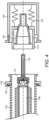
- the bayonet slot in the cap 104 can most clearly be seen in Figure 4 .
- the cap 104 is free to be pulled away and removed from the main body 102 of the drug delivery device 100, as shown in Figure 4 .
- the needle assembly 110 is secured to the cap via the pre-stressed biasing element 122 and the outer shield 120 is secured to or integral with the needle assembly 110, these elements are removed with the cap 104.
- the inner needle shield 118 remains secured to the needle holder 112 as the cap 104 is removed.
- the user is able to prepare the drug delivery device for injection in a process requiring only two steps. First the user rotates and removes the cap 104, causing the needle assembly to be released and the cartridge pierced. Then the inner needle shield 118 is removed to expose the needle.
- the needle holder 112 may be secured to the cartridge holder 108 by a friction connection.
- the presence of the needle 114 in the septum of the cartridge 106 may increase the quality of this friction connection.
- the inner surface of the needle holder 112 may comprise a relatively soft plastic, and the cutting element 132 on the distal end of the cartridge holder 108 may be embedded in this material under the force from the pre-stressed biasing element 122.
- the inner surface of the needle holder 112 and outer surface of the cartridge holder 108 may be provided with corresponding threads.
- a mechanism (not shown) may be provided to cause or allow rotation of either or both of the cartridge holder 108 and the needle holder 112 to cause the corresponding threads to engage.
- Figure 5 illustrates one exemplary way in which the outer shield 120 may be secured to the needle assembly 110.
- the pre-stressed biasing element 122 and cap 104 are omitted from Figure 5 for clarity.
- the outer shield 120 comprises one or more clips 134 at its proximal end which are received in one or more corresponding recesses 136 in the needle assembly 110. This configuration may aid in manufacture of the integrated cap assembly 101.
- the outer shield 120 may first be inserted from the proximal end of the needle assembly 110.
- the outer shield 120 is preferably made from a slightly resilient material, such as a plastic. As the inner diameter of the needle assembly 110 tapers inwards, the proximal end of the outer shield 120 is deformed until the clips 134 engage with the recesses 136.
- the outer shield 120 is then secured and cannot move axially in either direction.
- the needle holder 112 may then be inserted from the proximal end into the outer shield 120.
- the pierceable seal 116 may be attached to the needle holder 112 before or after its insertion into the outer shield 120.
- the assembly as shown in Figure 5 may then be secured within the cap 104.
- the pre-stressed biasing element 122 may be secured to the needle assembly 110 and stressed as the cap 104 is attached to the drug delivery device 100.
- a drug or medicament can include at least one small or large molecule, or combinations thereof, in various types of formulations, for the treatment of one or more diseases.
- exemplary pharmaceutically active compounds may include small molecules; polypeptides, peptides and proteins (e.g., hormones, growth factors, antibodies, antibody fragments, and enzymes); carbohydrates and polysaccharides; and nucleic acids, double or single stranded DNA (including naked and cDNA), RNA, antisense nucleic acids such as antisense DNA and RNA, small interfering RNA (siRNA), ribozymes, genes, and oligonucleotides. Nucleic acids may be incorporated into molecular delivery systems such as vectors, plasmids, or liposomes. Mixtures of one or more of these drugs are also contemplated.
- a drug delivery device shall encompass any type of device or system configured to dispense a drug into a human or animal body.
- a drug delivery device may be an injection device (e.g., syringe, pen injector, auto injector, large-volume device, pump, perfusion system, or other device configured for intraocular, subcutaneous, intramuscular, or intravascular delivery), skin patch (e.g., osmotic, chemical, micro-needle), inhaler (e.g., nasal or pulmonary), implantable (e.g., coated stent, capsule), or feeding systems for the gastrointestinal tract.
- the presently described drugs may be particularly useful with injection devices that include a needle, e.g., a small gauge needle.
- the drug or medicament may be contained in a primary package or "drug container" adapted for use with a drug delivery device.
- the drug container may be, e.g., a cartridge, syringe, reservoir, or other vessel configured to provide a suitable chamber for storage (e.g., short- or long-term storage) of one or more pharmaceutically active compounds.
- the chamber may be designed to store a drug for at least one day (e.g., 1 to at least 30 days).
- the chamber may be designed to store a drug for about 1 month to about 2 years. Storage may occur at room temperature (e.g., about 20°C), or refrigerated temperatures (e.g., from about - 4°C to about 4°C).
- the drug container may be or may include a dual-chamber cartridge configured to store two or more components of a drug formulation (e.g., a drug and a diluent, or two different types of drugs) separately, one in each chamber.
- the two chambers of the dual-chamber cartridge may be configured to allow mixing between the two or more components of the drug or medicament prior to and/or during dispensing into the human or animal body.
- the two chambers may be configured such that they are in fluid communication with each other (e.g., by way of a conduit between the two chambers) and allow mixing of the two components when desired by a user prior to dispensing.
- the two chambers may be configured to allow mixing as the components are being dispensed into the human or animal body.
- the drug delivery devices and drugs described herein can be used for the treatment and/or prophylaxis of many different types of disorders.
- exemplary disorders include, e.g., diabetes mellitus or complications associated with diabetes mellitus such as diabetic retinopathy, thromboembolism disorders such as deep vein or pulmonary thromboembolism.
- Further exemplary disorders are acute coronary syndrome (ACS), angina, myocardial infarction, cancer, macular degeneration, inflammation, hay fever, atherosclerosis and/or rheumatoid arthritis.
- ACS acute coronary syndrome
- angina myocardial infarction
- cancer macular degeneration
- inflammation hay fever
- atherosclerosis and/or rheumatoid arthritis.
- Exemplary drugs for the treatment and/or prophylaxis of diabetes mellitus or complications associated with diabetes mellitus include an insulin, e.g., human insulin, or a human insulin analogue or derivative, a glucagon-like peptide (GLP-1), GLP-1 analogues or GLP-1 receptor agonists, or an analogue or derivative thereof, a dipeptidyl peptidase-4 (DPP4) inhibitor, or a pharmaceutically acceptable salt or solvate thereof, or any mixture thereof.
- the term "derivative” refers to any substance which is sufficiently structurally similar to the original substance so as to have substantially similar functionality or activity (e.g., therapeutic effectiveness).
- Exemplary insulin analogues are Gly(A21), Arg(B31), Arg(B32) human insulin (insulin glargine); Lys(B3), Glu(B29) human insulin; Lys(B28), Pro(B29) human insulin; Asp(B28) human insulin; human insulin, wherein proline in position B28 is replaced by Asp, Lys, Leu, Val or Ala and wherein in position B29 Lys may be replaced by Pro; Ala(B26) human insulin; Des(B28-B30) human insulin; Des(B27) human insulin and Des(B30) human insulin.
- Exemplary insulin derivatives are, for example, B29-N-myristoyl-des(B30) human insulin; B29-N-palmitoyl-des(B30) human insulin; B29-N-myristoyl human insulin; B29-N-palmitoyl human insulin; B28-N-myristoyl LysB28ProB29 human insulin; B28-N-palmitoyl-LysB28ProB29 human insulin; B30-N-myristoyl-ThrB29LysB30 human insulin; B30-N-palmitoyl- ThrB29LysB30 human insulin; B29-N-(N-palmitoyl-gamma-glutamyl)-des(B30) human insulin; B29-N-(N-lithocholyl-gamma-glutamyl)-des(B30) human insulin; B29-N-( ⁇ -carboxyheptadecanoyl)-des(B30) human insulin and B29-N
- GLP-1, GLP-1 analogues and GLP-1 receptor agonists are, for example: Lixisenatide / AVE0010 / ZP10 / Lyxumia, Exenatide / Exendin-4 / Byetta / Bydureon / ITCA 650 / AC-2993 (a 39 amino acid peptide which is produced by the salivary glands of the Gila monster), Liraglutide / Victoza, Semaglutide, Taspoglutide, Syncria / Albiglutide, Dulaglutide, rExendin-4, CJC-1134-PC, PB-1023, TTP-054, Langlenatide / HM-11260C, CM-3, GLP-1 Eligen, ORMD-0901, NN-9924, NN-9926, NN-9927, Nodexen, Viador-GLP-1, CVX-096, ZYOG-1, ZYD-1, GSK-2374697, DA-3091, MAR-701
- An exemplary oligonucleotide is, for example: mipomersen / Kynamro, a cholesterol-reducing antisense therapeutic for the treatment of familial hypercholesterolemia.
- DPP4 inhibitors are Vildagliptin, Sitagliptin, Denagliptin, Saxagliptin, Berberine.
- hormones include hypophysis hormones or hypothalamus hormones or regulatory active peptides and their antagonists, such as Gonadotropine (Follitropin, Lutropin, Choriongonadotropin, Menotropin), Somatropine (Somatropin), Desmopressin, Terlipressin, Gonadorelin, Triptorelin, Leuprorelin, Buserelin, Nafarelin, and Goserelin.
- Gonadotropine Follitropin, Lutropin, Choriongonadotropin, Menotropin
- Somatropine Somatropin
- Desmopressin Terlipressin
- Gonadorelin Triptorelin
- Leuprorelin Buserelin
- Nafarelin Nafarelin
- Goserelin Goserelin.
- Exemplary polysaccharides include a glucosaminoglycane, a hyaluronic acid, a heparin, a low molecular weight heparin or an ultra-low molecular weight heparin or a derivative thereof, or a sulphated polysaccharide, e.g. a poly-sulphated form of the above-mentioned polysaccharides, and/or a pharmaceutically acceptable salt thereof.
- An example of a pharmaceutically acceptable salt of a poly-sulphated low molecular weight heparin is enoxaparin sodium.
- An example of a hyaluronic acid derivative is Hylan G-F 20 / Synvisc, a sodium hyaluronate.
- antibody refers to an immunoglobulin molecule or an antigen-binding portion thereof.
- antigen-binding portions of immunoglobulin molecules include F(ab) and F(ab')2 fragments, which retain the ability to bind antigen.
- the antibody can be polyclonal, monoclonal, recombinant, chimeric, de-immunized or humanized, fully human, non-human, (e.g., murine), or single chain antibody.
- the antibody has effector function and can fix complement.
- the antibody has reduced or no ability to bind an Fc receptor.
- the antibody can be an isotype or subtype, an antibody fragment or mutant, which does not support binding to an Fc receptor, e.g., it has a mutagenized or deleted Fc receptor binding region.
- fragment refers to a polypeptide derived from an antibody polypeptide molecule (e.g., an antibody heavy and/or light chain polypeptide) that does not comprise a full-length antibody polypeptide, but that still comprises at least a portion of a full-length antibody polypeptide that is capable of binding to an antigen.
- Antibody fragments can comprise a cleaved portion of a full length antibody polypeptide, although the term is not limited to such cleaved fragments.
- Antibody fragments that are useful in the present invention include, for example, Fab fragments, F(ab')2 fragments, scFv (single-chain Fv) fragments, linear antibodies, monospecific or multispecific antibody fragments such as bispecific, trispecific, and multispecific antibodies (e.g., diabodies, triabodies, tetrabodies), minibodies, chelating recombinant antibodies, tribodies or bibodies, intrabodies, nanobodies, small modular immunopharmaceuticals (SMIP), binding-domain immunoglobulin fusion proteins, camelized antibodies, and VHH containing antibodies. Additional examples of antigen-binding antibody fragments are known in the art.
- CDR complementarity-determining region
- framework region refers to amino acid sequences within the variable region of both heavy and light chain polypeptides that are not CDR sequences, and are primarily responsible for maintaining correct positioning of the CDR sequences to permit antigen binding.
- framework regions themselves typically do not directly participate in antigen binding, as is known in the art, certain residues within the framework regions of certain antibodies can directly participate in antigen binding or can affect the ability of one or more amino acids in CDRs to interact with antigen.
- Exemplary antibodies are anti PCSK-9 mAb (e.g., Alirocumab), anti IL-6 mAb (e.g., Sarilumab), and anti IL-4 mAb (e.g., Dupilumab).
- anti PCSK-9 mAb e.g., Alirocumab
- anti IL-6 mAb e.g., Sarilumab
- anti IL-4 mAb e.g., Dupilumab
- the compounds described herein may be used in pharmaceutical formulations comprising (a) the compound(s) or pharmaceutically acceptable salts thereof, and (b) a pharmaceutically acceptable carrier.
- the compounds may also be used in pharmaceutical formulations that include one or more other active pharmaceutical ingredients or in pharmaceutical formulations in which the present compound or a pharmaceutically acceptable salt thereof is the only active ingredient.
- the pharmaceutical formulations of the present disclosure encompass any formulation made by admixing a compound described herein and a pharmaceutically acceptable carrier.
- Pharmaceutically acceptable salts of any drug described herein are also contemplated for use in drug delivery devices.
- Pharmaceutically acceptable salts are for example acid addition salts and basic salts.
- Acid addition salts are e.g. HCl or HBr salts.
- Basic salts are e.g. salts having a cation selected from an alkali or alkaline earth metal, e.g.
- R1 to R4 independently of each other mean: hydrogen, an optionally substituted C1 C6-alkyl group, an optionally substituted C2-C6-alkenyl group, an optionally substituted C6-C10-aryl group, or an optionally substituted C6-C10-heteroaryl group.
- R1 to R4 independently of each other mean: hydrogen, an optionally substituted C1 C6-alkyl group, an optionally substituted C2-C6-alkenyl group, an optionally substituted C6-C10-aryl group, or an optionally substituted C6-C10-heteroaryl group.
- solvates are for example hydrates or alkanolates such as methanolates or ethanolates.
Landscapes
- Health & Medical Sciences (AREA)
- Vascular Medicine (AREA)
- Engineering & Computer Science (AREA)
- Anesthesiology (AREA)
- Biomedical Technology (AREA)
- Heart & Thoracic Surgery (AREA)
- Hematology (AREA)
- Life Sciences & Earth Sciences (AREA)
- Animal Behavior & Ethology (AREA)
- General Health & Medical Sciences (AREA)
- Public Health (AREA)
- Veterinary Medicine (AREA)
- Infusion, Injection, And Reservoir Apparatuses (AREA)
Claims (11)
- Kappe (12, 101, 104) für eine Medikamenten-Verabreichungsvorrichtung (10, 100), wobei die Kappe Folgendes aufweist:eine in der Kappe gehaltene Nadelbaugruppe (110) undein vorgespanntes Vorspannelement (122), das zwischen der Kappe und der Nadelbaugruppe angeordnet und dazu ausgestaltet ist, die Nadelbaugruppe proximal bezüglich der Medikamenten-Verabreichungsvorrichtung vorzuspannen, während die Kappe an einem Hauptkörper (102) der Medikamenten-Verabreichungsvorrichtung befestigt ist, wobei die Kappe dazu ausgestaltet ist, mittels Drehung zwischen einer Anfangsposition, einer Zwischenposition und einer Endposition bewegt zu werden, wobei die Drehung um eine sich zwischen einem distalen Ende der Medikamenten-Verabreichungsvorrichtung, an dem die Kappe angeordnet ist, und einem gegenüberliegenden proximalen Ende der Medikamenten-Verabreichungsvorrichtung erstreckenden Längsachse der Medikamenten-Verabreichungsvorrichtung erfolgt, und wobei die Kappe ferner zu Folgendem ausgestaltet ist:in einer Anfangsposition an der Medikamenten-Verabreichungsvorrichtung befestigt zu sein und Verriegelungselemente (126) der Kappe oder des Hauptkörpers in einer verriegelten Position zu halten, in einer Zwischenposition an der Medikamenten-Verabreichungsvorrichtung befestigt zu sein und die Verriegelungselemente freizugeben, damit die Nadelbaugruppe mit einer Kartusche (106) in Eingriff kommen kann, die in dem Hauptkörper der Medikamenten-Verabreichungsvorrichtung angeordnet ist, undin die Endposition gedreht zu werden, in der Vorsprünge (124) an dem Hauptkörper (102) der Medikamenten-Verabreichungsvorrichtung das Ende von Bajonettbefestigungsnuten in der Kappe erreichen, wodurch die Kappe von der Medikamenten-Verabreichungsvorrichtung gelöst werden kann.
- Kappe nach Anspruch 1, wobei das vorgespannte Vorspannmittel dazu ausgestaltet ist, die Nadelbaugruppe zu einer axialen Bewegung in der integrierten Kappenbaugruppe zu zwingen, nachdem die Kappe aus der Anfangsposition in die Zwischenposition bewegt worden ist, so dass die Nadelbaugruppe eine in dem Hauptkörper der Medikamenten-Verabreichungsvorrichtung gehaltene Kartusche kontaktiert.
- Kappe nach Anspruch 1 oder Anspruch 2, wobei ein proximales Ende der Nadelbaugruppe mit einer einstechbaren Dichtung (116) abgedeckt ist.
- Medikamenten-Verabreichungsvorrichtung (10, 100), aufweisend:eine Kappe (12, 101, 104) nach einem der Ansprüche 1 bis 3, wobei die Kappe freigebbar an einem Hauptkörper (102) der Medikamenten-Verabreichungsvorrichtung befestigt ist, unddas eine oder die mehreren Verriegelungselemente (126), die jeweils eine verriegelte Position und eine entriegelte Position haben, wobei die Verriegelungselemente in der verriegelten Position verhindern, dass die Nadelbaugruppe eine in dem Hauptkörper gehaltene Kartusche (106) in Eingriff zu nehmen.
- Medikamenten-Verabreichungsvorrichtung nach Anspruch 4, wobei jedes der Verriegelungselemente ein Verriegelungsglied (128) und ein Vorspannglied (130) aufweist, das zum Vorspannen des Verriegelungsglieds zu der entriegelten Position hin ausgestaltet ist.
- Medikamenten-Verabreichungsvorrichtung nach Anspruch 5, wobei das Vorspannglied zwischen dem Verriegelungsglied und einem Hauptkörper der Medikamenten-Verabreichungsvorrichtung angeordnet ist.
- Medikamenten-Verabreichungsvorrichtung nach Anspruch 5 oder 6, wobei die Nadelbaugruppe zur Anlage an den Verriegelungsgliedern ausgestaltet ist, wenn die Verriegelungsglieder in der verriegelten Position sind.
- Medikamenten-Verabreichungsvorrichtung nach einem der Ansprüche 4 bis 7, wobei die Medikamenten-Verabreichungsvorrichtung ferner einen Kartuschenhalter (108) und ein oder mehrere Schneidelemente (132) aufweist, die an einem distalen Ende des Kartuschenhalters gestützt sind, wobei die Schneidelemente dazu angeordnet sind, in die einstechbare Dichtung einzustechen, wenn die Nadelbaugruppe den Kartuschenhalter kontaktiert.
- Medikamenten-Verabreichungsvorrichtung nach Anspruch 8, wobei die Nadelbaugruppe einen äußeren Nadelschutz (120) und einen inneren Nadelschutz (118) aufweist und wobei durch das Entfernen der Kappe von der Medikamenten-Verabreichungsvorrichtung auch der äußere Nadelschutz entfernt wird, und optional wobei der äußere Nadelschutz einen oder mehrere federnd deformierbare Clips (134) aufweist, die dazu ausgestaltet sind, zu gestatten, dass der äußere Nadelschutz axial in der Nadelbaugruppe befestigt wird.
- Medikamenten-Verabreichungsvorrichtung nach Anspruch 9, wobei die Nadelbaugruppe ferner eine von einem Nadelhalter (112) gestützte Nadel (17, 114) aufweist, wobei der Nadelhalter in dem äußeren Nadelschutz gehalten ist und der Nadelhalter dazu ausgestaltet ist, den Kartuschenhalter mittels einer Reibung oder einer Gewindeverbindung in Eingriff zu nehmen, um die Nadel an der Kartusche zu befestigen.
- Medikamenten-Verabreichungsvorrichtung nach einem der Ansprüche 4 bis 10, ferner aufweisend ein in der Kartusche enthaltenes Medikament.
Applications Claiming Priority (2)
| Application Number | Priority Date | Filing Date | Title |
|---|---|---|---|
| EP15196710 | 2015-11-27 | ||
| PCT/EP2016/078275 WO2017089285A1 (en) | 2015-11-27 | 2016-11-21 | A drug delivery device with a cap |
Publications (3)
| Publication Number | Publication Date |
|---|---|
| EP3380148A1 EP3380148A1 (de) | 2018-10-03 |
| EP3380148B1 true EP3380148B1 (de) | 2024-08-28 |
| EP3380148C0 EP3380148C0 (de) | 2024-08-28 |
Family
ID=54705509
Family Applications (1)
| Application Number | Title | Priority Date | Filing Date |
|---|---|---|---|
| EP16798208.1A Active EP3380148B1 (de) | 2015-11-27 | 2016-11-21 | Wirkstoffabgabevorrichtung mit kappe |
Country Status (5)
| Country | Link |
|---|---|
| US (1) | US10881810B2 (de) |
| EP (1) | EP3380148B1 (de) |
| JP (1) | JP6861707B2 (de) |
| CN (1) | CN108601902B (de) |
| WO (1) | WO2017089285A1 (de) |
Families Citing this family (9)
| Publication number | Priority date | Publication date | Assignee | Title |
|---|---|---|---|---|
| EP3492123A1 (de) | 2017-12-01 | 2019-06-05 | Sanofi | Injektorvorrichtung |
| EP3492125A1 (de) * | 2017-12-01 | 2019-06-05 | Sanofi | Injektorvorrichtung |
| USD866863S1 (en) * | 2019-01-03 | 2019-11-12 | Sandbar Hand Care, LLC | Callus management bar |
| JP2022529882A (ja) | 2019-03-12 | 2022-06-27 | サノフイ | 薬剤レベルを測定するための装置 |
| KR102119008B1 (ko) * | 2019-09-16 | 2020-06-04 | 이문기 | 유체 주입 장치 및 방법 |
| KR102393769B1 (ko) * | 2019-09-16 | 2022-05-02 | 이문기 | 유체 주입 장치 및 방법 |
| US12005244B2 (en) | 2020-03-27 | 2024-06-11 | Medivena Sp. Z O.O. | Needle-based device based on direct wing-based coupling of a needle shield to a barrel thereof and safety mechanism implemented therein |
| USD1014857S1 (en) | 2020-09-17 | 2024-02-13 | Sandbar Hand Care, LLC | Foot callus management bar |
| US20240033441A1 (en) * | 2020-12-02 | 2024-02-01 | Sanofi | Drug Delivery Device |
Family Cites Families (10)
| Publication number | Priority date | Publication date | Assignee | Title |
|---|---|---|---|---|
| US3825003A (en) * | 1972-12-26 | 1974-07-23 | Vca Metal Fab Inc | Sealed-hypodermic syringe |
| FR2913201B1 (fr) * | 2007-03-02 | 2009-11-20 | Becton Dickinson France | Protection pour couvrir l'extremite d'un dispositif d'administration ou d'un sous-ensemble,sous-ensemble et dispositif d'administration |
| EP2544741B1 (de) | 2010-03-09 | 2016-05-11 | SHL Group AB | Vorrichtung zur medikamentenverabreichung |
| WO2012089821A1 (en) * | 2010-12-31 | 2012-07-05 | Novo Nordisk A/S | Medical injection device |
| CH705692A2 (de) * | 2011-11-03 | 2013-05-15 | Tecpharma Licensing Ag | Verabreichungsvorrichtung zum Abmischen eines Wirkstoffs mit einer Lösungsflüssigkeit. |
| EP2703022A1 (de) * | 2012-09-03 | 2014-03-05 | LTS LOHMANN Therapie-Systeme AG | Einmalinjektor mit zweistufiger Auslösung |
| CN203090089U (zh) * | 2013-02-21 | 2013-07-31 | 南阳医学高等专科学校第一附属医院 | 一种便携式胰岛素泵助针装置 |
| GB2520563B (en) * | 2013-11-26 | 2015-12-23 | Owen Mumford Ltd | Injector devices |
| EP2878319A1 (de) * | 2013-11-28 | 2015-06-03 | Sanofi-Aventis Deutschland GmbH | Muffenabzieher |
| JP6647205B2 (ja) * | 2014-02-06 | 2020-02-14 | ノボ・ノルデイスク・エー/エス | 組み合わせられたカートリッジおよび針アセンブリ |
-
2016
- 2016-11-21 EP EP16798208.1A patent/EP3380148B1/de active Active
- 2016-11-21 CN CN201680080062.5A patent/CN108601902B/zh active Active
- 2016-11-21 US US15/778,501 patent/US10881810B2/en active Active
- 2016-11-21 JP JP2018527155A patent/JP6861707B2/ja active Active
- 2016-11-21 WO PCT/EP2016/078275 patent/WO2017089285A1/en not_active Ceased
Also Published As
| Publication number | Publication date |
|---|---|
| JP6861707B2 (ja) | 2021-04-21 |
| US20180344943A1 (en) | 2018-12-06 |
| EP3380148C0 (de) | 2024-08-28 |
| WO2017089285A1 (en) | 2017-06-01 |
| US10881810B2 (en) | 2021-01-05 |
| EP3380148A1 (de) | 2018-10-03 |
| JP2018535055A (ja) | 2018-11-29 |
| CN108601902B (zh) | 2021-07-02 |
| CN108601902A (zh) | 2018-09-28 |
Similar Documents
| Publication | Publication Date | Title |
|---|---|---|
| US12514973B2 (en) | Drug delivery device with a cap | |
| US11904151B2 (en) | Cap for an injection device | |
| US10881810B2 (en) | Drug delivery device with a cap | |
| US11439770B2 (en) | Injection device | |
| EP3703788A1 (de) | Injektorvorrichtung | |
| EP3380165B1 (de) | Medikamenteninjektionsvorrichtung mit federunterstützter nadelschutzkappe | |
| US12214179B2 (en) | Injector device | |
| EP3380152B1 (de) | Medikamenteninjektionsvorrichtung | |
| EP3727501B1 (de) | Injektorvorrichtung | |
| US11364345B2 (en) | Medicament injector device | |
| EP3492125A1 (de) | Injektorvorrichtung | |
| US20200054839A1 (en) | Medicament injection device | |
| US11426530B2 (en) | Needle shield removal mechanism for injection device | |
| HK1254446B (en) | A drug delivery device with a cap |
Legal Events
| Date | Code | Title | Description |
|---|---|---|---|
| STAA | Information on the status of an ep patent application or granted ep patent |
Free format text: STATUS: UNKNOWN |
|
| STAA | Information on the status of an ep patent application or granted ep patent |
Free format text: STATUS: THE INTERNATIONAL PUBLICATION HAS BEEN MADE |
|
| PUAI | Public reference made under article 153(3) epc to a published international application that has entered the european phase |
Free format text: ORIGINAL CODE: 0009012 |
|
| STAA | Information on the status of an ep patent application or granted ep patent |
Free format text: STATUS: REQUEST FOR EXAMINATION WAS MADE |
|
| 17P | Request for examination filed |
Effective date: 20180627 |
|
| AK | Designated contracting states |
Kind code of ref document: A1 Designated state(s): AL AT BE BG CH CY CZ DE DK EE ES FI FR GB GR HR HU IE IS IT LI LT LU LV MC MK MT NL NO PL PT RO RS SE SI SK SM TR |
|
| AX | Request for extension of the european patent |
Extension state: BA ME |
|
| DAV | Request for validation of the european patent (deleted) | ||
| DAX | Request for extension of the european patent (deleted) | ||
| STAA | Information on the status of an ep patent application or granted ep patent |
Free format text: STATUS: EXAMINATION IS IN PROGRESS |
|
| 17Q | First examination report despatched |
Effective date: 20201028 |
|
| GRAP | Despatch of communication of intention to grant a patent |
Free format text: ORIGINAL CODE: EPIDOSNIGR1 |
|
| STAA | Information on the status of an ep patent application or granted ep patent |
Free format text: STATUS: GRANT OF PATENT IS INTENDED |
|
| INTG | Intention to grant announced |
Effective date: 20240531 |
|
| GRAS | Grant fee paid |
Free format text: ORIGINAL CODE: EPIDOSNIGR3 |
|
| GRAA | (expected) grant |
Free format text: ORIGINAL CODE: 0009210 |
|
| STAA | Information on the status of an ep patent application or granted ep patent |
Free format text: STATUS: THE PATENT HAS BEEN GRANTED |
|
| AK | Designated contracting states |
Kind code of ref document: B1 Designated state(s): AL AT BE BG CH CY CZ DE DK EE ES FI FR GB GR HR HU IE IS IT LI LT LU LV MC MK MT NL NO PL PT RO RS SE SI SK SM TR |
|
| REG | Reference to a national code |
Ref country code: GB Ref legal event code: FG4D |
|
| REG | Reference to a national code |
Ref country code: CH Ref legal event code: EP |
|
| REG | Reference to a national code |
Ref country code: DE Ref legal event code: R096 Ref document number: 602016089136 Country of ref document: DE |
|
| REG | Reference to a national code |
Ref country code: IE Ref legal event code: FG4D |
|
| U01 | Request for unitary effect filed |
Effective date: 20240923 |
|
| U07 | Unitary effect registered |
Designated state(s): AT BE BG DE DK EE FI FR IT LT LU LV MT NL PT RO SE SI Effective date: 20241015 |
|
| U20 | Renewal fee for the european patent with unitary effect paid |
Year of fee payment: 9 Effective date: 20241021 |
|
| PG25 | Lapsed in a contracting state [announced via postgrant information from national office to epo] |
Ref country code: NO Free format text: LAPSE BECAUSE OF FAILURE TO SUBMIT A TRANSLATION OF THE DESCRIPTION OR TO PAY THE FEE WITHIN THE PRESCRIBED TIME-LIMIT Effective date: 20241128 |
|
| PG25 | Lapsed in a contracting state [announced via postgrant information from national office to epo] |
Ref country code: PL Free format text: LAPSE BECAUSE OF FAILURE TO SUBMIT A TRANSLATION OF THE DESCRIPTION OR TO PAY THE FEE WITHIN THE PRESCRIBED TIME-LIMIT Effective date: 20240828 Ref country code: GR Free format text: LAPSE BECAUSE OF FAILURE TO SUBMIT A TRANSLATION OF THE DESCRIPTION OR TO PAY THE FEE WITHIN THE PRESCRIBED TIME-LIMIT Effective date: 20241129 |
|
| PG25 | Lapsed in a contracting state [announced via postgrant information from national office to epo] |
Ref country code: IS Free format text: LAPSE BECAUSE OF FAILURE TO SUBMIT A TRANSLATION OF THE DESCRIPTION OR TO PAY THE FEE WITHIN THE PRESCRIBED TIME-LIMIT Effective date: 20241228 |
|
| PG25 | Lapsed in a contracting state [announced via postgrant information from national office to epo] |
Ref country code: HR Free format text: LAPSE BECAUSE OF FAILURE TO SUBMIT A TRANSLATION OF THE DESCRIPTION OR TO PAY THE FEE WITHIN THE PRESCRIBED TIME-LIMIT Effective date: 20240828 |
|
| PG25 | Lapsed in a contracting state [announced via postgrant information from national office to epo] |
Ref country code: RS Free format text: LAPSE BECAUSE OF FAILURE TO SUBMIT A TRANSLATION OF THE DESCRIPTION OR TO PAY THE FEE WITHIN THE PRESCRIBED TIME-LIMIT Effective date: 20241128 Ref country code: ES Free format text: LAPSE BECAUSE OF FAILURE TO SUBMIT A TRANSLATION OF THE DESCRIPTION OR TO PAY THE FEE WITHIN THE PRESCRIBED TIME-LIMIT Effective date: 20240828 |
|
| PG25 | Lapsed in a contracting state [announced via postgrant information from national office to epo] |
Ref country code: RS Free format text: LAPSE BECAUSE OF FAILURE TO SUBMIT A TRANSLATION OF THE DESCRIPTION OR TO PAY THE FEE WITHIN THE PRESCRIBED TIME-LIMIT Effective date: 20241128 Ref country code: PL Free format text: LAPSE BECAUSE OF FAILURE TO SUBMIT A TRANSLATION OF THE DESCRIPTION OR TO PAY THE FEE WITHIN THE PRESCRIBED TIME-LIMIT Effective date: 20240828 Ref country code: NO Free format text: LAPSE BECAUSE OF FAILURE TO SUBMIT A TRANSLATION OF THE DESCRIPTION OR TO PAY THE FEE WITHIN THE PRESCRIBED TIME-LIMIT Effective date: 20241128 Ref country code: IS Free format text: LAPSE BECAUSE OF FAILURE TO SUBMIT A TRANSLATION OF THE DESCRIPTION OR TO PAY THE FEE WITHIN THE PRESCRIBED TIME-LIMIT Effective date: 20241228 Ref country code: HR Free format text: LAPSE BECAUSE OF FAILURE TO SUBMIT A TRANSLATION OF THE DESCRIPTION OR TO PAY THE FEE WITHIN THE PRESCRIBED TIME-LIMIT Effective date: 20240828 Ref country code: GR Free format text: LAPSE BECAUSE OF FAILURE TO SUBMIT A TRANSLATION OF THE DESCRIPTION OR TO PAY THE FEE WITHIN THE PRESCRIBED TIME-LIMIT Effective date: 20241129 Ref country code: ES Free format text: LAPSE BECAUSE OF FAILURE TO SUBMIT A TRANSLATION OF THE DESCRIPTION OR TO PAY THE FEE WITHIN THE PRESCRIBED TIME-LIMIT Effective date: 20240828 |
|
| PG25 | Lapsed in a contracting state [announced via postgrant information from national office to epo] |
Ref country code: SM Free format text: LAPSE BECAUSE OF FAILURE TO SUBMIT A TRANSLATION OF THE DESCRIPTION OR TO PAY THE FEE WITHIN THE PRESCRIBED TIME-LIMIT Effective date: 20240828 |
|
| PG25 | Lapsed in a contracting state [announced via postgrant information from national office to epo] |
Ref country code: CZ Free format text: LAPSE BECAUSE OF FAILURE TO SUBMIT A TRANSLATION OF THE DESCRIPTION OR TO PAY THE FEE WITHIN THE PRESCRIBED TIME-LIMIT Effective date: 20240828 |
|
| PG25 | Lapsed in a contracting state [announced via postgrant information from national office to epo] |
Ref country code: SK Free format text: LAPSE BECAUSE OF FAILURE TO SUBMIT A TRANSLATION OF THE DESCRIPTION OR TO PAY THE FEE WITHIN THE PRESCRIBED TIME-LIMIT Effective date: 20240828 |
|
| PLBE | No opposition filed within time limit |
Free format text: ORIGINAL CODE: 0009261 |
|
| STAA | Information on the status of an ep patent application or granted ep patent |
Free format text: STATUS: NO OPPOSITION FILED WITHIN TIME LIMIT |
|
| PG25 | Lapsed in a contracting state [announced via postgrant information from national office to epo] |
Ref country code: MC Free format text: LAPSE BECAUSE OF FAILURE TO SUBMIT A TRANSLATION OF THE DESCRIPTION OR TO PAY THE FEE WITHIN THE PRESCRIBED TIME-LIMIT Effective date: 20240828 |
|
| 26N | No opposition filed |
Effective date: 20250530 |
|
| PG25 | Lapsed in a contracting state [announced via postgrant information from national office to epo] |
Ref country code: IE Free format text: LAPSE BECAUSE OF NON-PAYMENT OF DUE FEES Effective date: 20241121 |
|
| U20 | Renewal fee for the european patent with unitary effect paid |
Year of fee payment: 10 Effective date: 20251008 |
|
| REG | Reference to a national code |
Ref country code: CH Ref legal event code: U11 Free format text: ST27 STATUS EVENT CODE: U-0-0-U10-U11 (AS PROVIDED BY THE NATIONAL OFFICE) Effective date: 20251201 |
|
| PGFP | Annual fee paid to national office [announced via postgrant information from national office to epo] |
Ref country code: GB Payment date: 20251001 Year of fee payment: 10 |
|
| PGFP | Annual fee paid to national office [announced via postgrant information from national office to epo] |
Ref country code: CH Payment date: 20251201 Year of fee payment: 10 |
|
| PG25 | Lapsed in a contracting state [announced via postgrant information from national office to epo] |
Ref country code: HU Free format text: LAPSE BECAUSE OF FAILURE TO SUBMIT A TRANSLATION OF THE DESCRIPTION OR TO PAY THE FEE WITHIN THE PRESCRIBED TIME-LIMIT; INVALID AB INITIO Effective date: 20161121 |
|
| PG25 | Lapsed in a contracting state [announced via postgrant information from national office to epo] |
Ref country code: CY Free format text: LAPSE BECAUSE OF FAILURE TO SUBMIT A TRANSLATION OF THE DESCRIPTION OR TO PAY THE FEE WITHIN THE PRESCRIBED TIME-LIMIT; INVALID AB INITIO Effective date: 20161121 |