EP3380253B1 - Austauschbares mittelteil für glasbeschichtungshaube - Google Patents
Austauschbares mittelteil für glasbeschichtungshaube Download PDFInfo
- Publication number
- EP3380253B1 EP3380253B1 EP16869110.3A EP16869110A EP3380253B1 EP 3380253 B1 EP3380253 B1 EP 3380253B1 EP 16869110 A EP16869110 A EP 16869110A EP 3380253 B1 EP3380253 B1 EP 3380253B1
- Authority
- EP
- European Patent Office
- Prior art keywords
- insert
- chamber
- panel
- housing structure
- pressurized air
- Prior art date
- Legal status (The legal status is an assumption and is not a legal conclusion. Google has not performed a legal analysis and makes no representation as to the accuracy of the status listed.)
- Not-in-force
Links
Images


Classifications
-
- B—PERFORMING OPERATIONS; TRANSPORTING
- B05—SPRAYING OR ATOMISING IN GENERAL; APPLYING FLUENT MATERIALS TO SURFACES, IN GENERAL
- B05B—SPRAYING APPARATUS; ATOMISING APPARATUS; NOZZLES
- B05B1/00—Nozzles, spray heads or other outlets, with or without auxiliary devices such as valves, heating means
- B05B1/14—Nozzles, spray heads or other outlets, with or without auxiliary devices such as valves, heating means with multiple outlet openings; with strainers in or outside the outlet opening
- B05B1/20—Perforated pipes or troughs, e.g. spray booms; Outlet elements therefor
-
- C—CHEMISTRY; METALLURGY
- C03—GLASS; MINERAL OR SLAG WOOL
- C03C—CHEMICAL COMPOSITION OF GLASSES, GLAZES OR VITREOUS ENAMELS; SURFACE TREATMENT OF GLASS; SURFACE TREATMENT OF FIBRES OR FILAMENTS MADE FROM GLASS, MINERALS OR SLAGS; JOINING GLASS TO GLASS OR OTHER MATERIALS
- C03C17/00—Surface treatment of glass, not in the form of fibres or filaments, by coating
- C03C17/001—General methods for coating; Devices therefor
- C03C17/002—General methods for coating; Devices therefor for flat glass, e.g. float glass
-
- B—PERFORMING OPERATIONS; TRANSPORTING
- B05—SPRAYING OR ATOMISING IN GENERAL; APPLYING FLUENT MATERIALS TO SURFACES, IN GENERAL
- B05B—SPRAYING APPARATUS; ATOMISING APPARATUS; NOZZLES
- B05B12/00—Arrangements for controlling delivery; Arrangements for controlling the spray area
- B05B12/16—Arrangements for controlling delivery; Arrangements for controlling the spray area for controlling the spray area
- B05B12/18—Arrangements for controlling delivery; Arrangements for controlling the spray area for controlling the spray area using fluids, e.g. gas streams
-
- C—CHEMISTRY; METALLURGY
- C03—GLASS; MINERAL OR SLAG WOOL
- C03C—CHEMICAL COMPOSITION OF GLASSES, GLAZES OR VITREOUS ENAMELS; SURFACE TREATMENT OF GLASS; SURFACE TREATMENT OF FIBRES OR FILAMENTS MADE FROM GLASS, MINERALS OR SLAGS; JOINING GLASS TO GLASS OR OTHER MATERIALS
- C03C17/00—Surface treatment of glass, not in the form of fibres or filaments, by coating
- C03C17/001—General methods for coating; Devices therefor
- C03C17/003—General methods for coating; Devices therefor for hollow ware, e.g. containers
- C03C17/005—Coating the outside
-
- C—CHEMISTRY; METALLURGY
- C03—GLASS; MINERAL OR SLAG WOOL
- C03C—CHEMICAL COMPOSITION OF GLASSES, GLAZES OR VITREOUS ENAMELS; SURFACE TREATMENT OF GLASS; SURFACE TREATMENT OF FIBRES OR FILAMENTS MADE FROM GLASS, MINERALS OR SLAGS; JOINING GLASS TO GLASS OR OTHER MATERIALS
- C03C17/00—Surface treatment of glass, not in the form of fibres or filaments, by coating
- C03C17/22—Surface treatment of glass, not in the form of fibres or filaments, by coating with other inorganic material
- C03C17/23—Oxides
- C03C17/245—Oxides by deposition from the vapour phase
-
- C—CHEMISTRY; METALLURGY
- C03—GLASS; MINERAL OR SLAG WOOL
- C03C—CHEMICAL COMPOSITION OF GLASSES, GLAZES OR VITREOUS ENAMELS; SURFACE TREATMENT OF GLASS; SURFACE TREATMENT OF FIBRES OR FILAMENTS MADE FROM GLASS, MINERALS OR SLAGS; JOINING GLASS TO GLASS OR OTHER MATERIALS
- C03C2218/00—Methods for coating glass
- C03C2218/10—Deposition methods
- C03C2218/11—Deposition methods from solutions or suspensions
- C03C2218/112—Deposition methods from solutions or suspensions by spraying
-
- C—CHEMISTRY; METALLURGY
- C03—GLASS; MINERAL OR SLAG WOOL
- C03C—CHEMICAL COMPOSITION OF GLASSES, GLAZES OR VITREOUS ENAMELS; SURFACE TREATMENT OF GLASS; SURFACE TREATMENT OF FIBRES OR FILAMENTS MADE FROM GLASS, MINERALS OR SLAGS; JOINING GLASS TO GLASS OR OTHER MATERIALS
- C03C2218/00—Methods for coating glass
- C03C2218/10—Deposition methods
- C03C2218/15—Deposition methods from the vapour phase
Definitions
- This invention relates to a coating hood for coating glass containers.
- the exterior surface of the glass container is typically coated with a metal-oxide coating, for example, to improve its structural integrity.
- Coating hoods are disclosed in U.S. Patent Application Pub. No. 2015/0101537 ; U.S. Patent Nos. 4389234 , 5081953 , 5140940 , 5454873 , 5599369 , 5584903 , 4668268 , 4879970 ; and PCT Patent App. Pub. No. WO1996020142 .
- coating vapor is sprayed onto the exterior surface of a glass container as the glass container passes either below or under a center section of the coating hood.
- the coating is typically prevented from being applied to the closure region of the container, known in the art as the "finish," by an air stream that is delivered through the center section of the coating hood and onto the closure of the container.
- the air stream creates a buffer zone that substantially prevents the coating material from settling on the finish.
- an apparatus for coating glass articles as from claim 1 is disclosed.
- a kit for coating glass articles comprises the above-described elongated housing structure and a plurality of inserts.
- Each insert is configured to be removably positioned on the mounting surface, and each insert has apertures for distributing the air or other fluid from the chamber and onto a surface of the glass articles.
- Each insert has a different arrangement of apertures for directing the air or other fluid onto the glass articles.
- a method for changing an airflow pattern in an apparatus for coating glass articles comprises the steps of:
- FIG. 1A depicts a perspective view of a center section 12 of a coating hood, according to one example of the invention.
- FIG. 1B depicts a perspective view of center section 12 of FIG. 1A , wherein the interchangeable insert 13 is shown partially disassembled from the remainder of the center section 12.
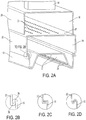
- FIG. 2A depicts a cross-sectional view of center section 12 taken along the lines 2A-2A in FIG. 1A . It should be understood that the entire coating hood is not shown in these figures.
- Center section 12 generally includes a conduit 14, an upper panel 20, a lower panel 22 and an interchangeable insert 13 that are interconnected to form an interior passageway. Air or other fluid is distributed from a source of pressurized air (not shown) connected to conduit 14 through the interior passageway of center section 12 onto glass containers (not shown) positioned beneath insert 13.
- the source of pressurized air may be a blower, a fan, or a compressed air cylinder, for example.
- the source of pressurized air may be referred to as a blower hereinafter.
- upper panel 20, lower panel 22 and insert 13 have approximately the same length and width dimensions to ensure that air will circulate across the entire length of center section 12.
- the length-wise and width-wise surfaces of upper panel 20, lower panel 22 and insert 13 may be flush.
- Upper panel 20 may be slightly shorter in length than lower panel 22 and insert 13, as shown, to accommodate a bracket 17 on the top surface of lower panel 22.
- upper panel 20 and lower panel 22 are shown as rectangular in cross-section, it should be understood that those panels may be square or circular in cross-section, for example, or any other shape that is capable of carrying air.
- conduit 14 extends in a vertical direction and has a hollow rectangular-shaped body.
- the top end of conduit 14 is either directly or indirectly connected to one or more fans/blowers that are configured to deliver air (or any other fluid) into center section 12.
- the bottom end of conduit 14 is both connected to and is in fluid communication with an opening formed in the top side of upper panel 20.
- Conduit 14 may be attached to upper panel 20 by a weld or a fastener, for example.
- conduit 14 is shown having a rectangular-shaped body, those of ordinary skill in the art will recognize that conduit 14 may be tubular or have any other shape that is capable of carrying air.
- Upper panel 20 is an elongated, three-sided, U-shaped panel comprising a horizontal wall and two depending legs forming vertical walls that extend beneath the horizontal wall.
- the horizontal wall of panel 20 includes an opening (not shown) on its top surface that is connected to the lower end of conduit 14.
- a hollow elongated upper chamber 16 is formed between the interior surfaces of upper panel 20 and a top wall 25 of lower panel 22.
- the front and rear facing surfaces of panel 20 are covered by covers 21. Covers 21 may be either separate from panel 20 or integrated with panel 20.
- a bracket 17 is fixedly positioned on the top wall of upper panel 20, and a pin 19 is mounted in bracket 17.
- pin 19 is mounted to an end of a vertically extending rod (not shown) that extends above center section 12. The rod is moved in the vertical direction in order to adjust the vertical position of the center section 12 so that center section 12 can accommodate glass containers of varying height.
- the rod is moved in the vertical direction in order to adjust the vertical position of the center section 12 so that center section 12 can accommodate glass containers of varying height.
- each vertical wall of panel 20 is connected to the upper surface of lower panel 22.
- the vertical walls of panel 20 may be attached to panel 22 by a weld or a fastener, for example.
- panels 20 and 22 may be integrated together.
- Lower panel 22 is another elongated, three-sided, U-shaped panel comprising a horizontal wall 25 and two depending legs forming vertical walls that extend beneath horizontal wall 25.
- Horizontal wall 25 includes a series of openings 23 (four rows shown) permitting the passage of air from chamber 16 to chamber 18.
- horizontal wall 25 of panel 22 may be a separate component that is removably positioned within center section 12 to change the airflow path between chambers 16 and 18.
- chamber 16 could be provided in the form of a conduit that is positioned inside of chamber 18 to deliver air or other fluid into chamber 18.
- access panel 32 is covered by access panel 32, and the rear facing surface of panel 22 (not shown) is covered by a cover (not shown).
- Access panel 32 is mounted to the front-facing surface of panel 22 by one or more fasteners 34. Access panel 32 extends to an elevation either at or below rail 26 such that access panel 32 retains insert 13 inside of center section 12.
- Insert 13 is positioned at an elevation beneath lower panel 22 such that a second hollow elongated lower chamber 18 is formed between the interior surfaces of lower panel 22 and the top-facing surface(s) of insert 13.
- Insert 13 is positioned on a mounting surface defined on the free ends of each vertical wall of lower panel 22.
- the free ends of the vertical walls of lower panel 22 are the ends of panel 22 that are unconstrained and that are not mounted to upper panel 20. More particularly, as shown in the detailed view of FIG. 2B , the free end of each vertical wall of panel 22 includes a U-shaped rail 26 in the form of a curved lip that engages with a complimentary U-shaped rail 28 that is formed on the free end of each side of insert 13. Rail 26 may also be referred to herein as a mounting surface.
- each rail may include a flat perpendicular surface or a V-shape, as shown in FIGs. 2C and 2D , respectively.
- Rails 26 and 28 are not fixedly mounted together by a weld, for example.
- insert 13 is not fixedly mounted to or integrated with panel 22. According to one aspect of the invention, no fasteners are required to mount insert 13 to panel 22. Those of ordinary skill in the art will recognize that other mounting arrangements for insert 13 exist.
- Insert 13 comprises apertures 29 that are configured to direct air or other fluid onto a specific area of a glass container (e.g., the finish of the container) during the glass coating process.
- Apertures 29 may be openings, slots, slits or perforations, for example.
- the glass container travels along the length dimension of center section 12 at a location that is either adjacent or directly adjacent lower facing surface 27 of insert 13.
- the glass containers are spaced from surface 27 by less than 5 inches. More preferably, the glass containers are spaced from surface 27 by less than 3 inches.
- insert 13 and location of apertures 29 may vary from that which is shown in FIG. 2A .
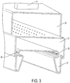
- Alternative inserts 13' and 13" are shown in FIGs. 3 and 4 , respectively, and it should be understood that further alternative designs exist.
- Insert 13 of FIG. 2A has a series of bends for accommodating a container having a wide-shaped container opening, for example.
- Insert 13' of FIG. 3 also has a series of bends for accommodating a container having a wide-shaped container opening, for example.
- Insert 13" shown in FIG. 4 is a flat sheet having no bends, and at least a portion of its surface is perforated with apertures 29. Insert 13" may be used for delivering air onto the finish of glass beer bottles, for example.
- apertures 29 defined in insert 13' are positioned at a higher elevation than apertures 29 defined in inserts 13 and 13'.
- insert 13 and 13' both extend downward to an elevation beneath the rail 26, whereas the entirety of insert 13" sits at an elevation above rail 26.
- insert 13 and panels 20 and 22 of center section 12 are optionally formed from aluminum or steel sheet metal, for example.
- those components of center section 12 may be formed from a plastic material, if so desired.
- Insert 13 may be a unitary, integral and monolithic component, as shown, that is formed from one piece of material. Insert 13 may be formed from any material that is known to those of ordinary skill in the art.
- the blowers or other source of pressurized air delivers air (or other process fluid) through conduit 14 and into upper chamber 16, as indicated by the vertical arrow in FIG. 1A .
- Upper chamber 16 acts as a manifold in that the air is uniformly distributed over the entire length of upper chamber 16.
- the air passes then through openings 23 of wall 25 and into lower chamber 18.
- Lower chamber 18 also acts as a manifold in that the air is uniformly distributed over the entire length of lower chamber 18.
- the air then passes through apertures 29 in insert 13, and the air is then directed onto the surfaces of the glass containers (e.g., the finish of the containers, which is not shown) that face the lower-facing surfaces 27 of insert 13.
- the chemical coating is not delivered through the insert 13, rather, it is sprayed onto the glass container by a separate spray device (not shown).
- insert 13' First, rails 28 of insert 13' are positioned on top of rails 26 of panel 22, and then insert 13' is slid in a forward horizontal direction until the rear end of insert 13' abuts with a rear surface (not shown) of panel 22. Panel 32 is then reinstalled to captivate insert 13' inside center section 12. The lower edge 35 of panel 32 extends to an elevation beneath the rails 28 of insert 13' so that insert 13' (or any other insert) cannot be removed without first removing panel 32.
- the insert can be hot-swapped, i.e., replaced without halting operation of the entire coating hood, with another insert in a matter of minutes, thereby minimizing downtime for the coating hood.
- the insert can be hot-swapped with another insert in less than 10 minutes. More preferably, the insert can be hot-swapped with another insert in less than 5 minutes.
- inserts 13, 13' and 13" may all be provided in the form of a kit that is provided along with center section 12. An end-user can select the appropriate insert 13, 13' and 13" for use in a particular coating operation.
Landscapes
- Chemical & Material Sciences (AREA)
- Life Sciences & Earth Sciences (AREA)
- Engineering & Computer Science (AREA)
- Chemical Kinetics & Catalysis (AREA)
- General Chemical & Material Sciences (AREA)
- Geochemistry & Mineralogy (AREA)
- Materials Engineering (AREA)
- Organic Chemistry (AREA)
- Surface Treatment Of Glass (AREA)
- Re-Forming, After-Treatment, Cutting And Transporting Of Glass Products (AREA)
- Details Of Rigid Or Semi-Rigid Containers (AREA)
Claims (18)
- Vorrichtung (12) zum Beschichten von Glasgegenständen, umfassend:eine längliche Gehäusestruktur (22) mit (i) zwei oder mehr Wänden (25), die eine Innenkammer (18) zur Aufnahme von Druckluft oder einem anderen Fluid definieren, und (ii) eine Montagefläche (26), die zumindest entlang eines Abschnitts einer der Wände definiert ist; undeinen Einsatz (13), der entfernbar auf der Montagefläche (26) ausgebildet ist, wobei der Einsatz (13) Aperturen (29) zum Verteilen der Druckluft oder des anderen Fluids aus der Kammer (18) auf eine Oberfläche von Glasgegenständen aufweist, die benachbart zum Einsatz (13) positioniert sind,wobei die Gehäusestruktur (22) eine Platte mit einer ersten Wand (25) und zwei senkrechten Wänden umfasst, die sich im Wesentlichen senkrecht von gegenüberliegenden Seiten der ersten Wand (25) erstrecken, und wobei die Montagefläche (26) auf einem freien Ende jeder senkrechten Wand definiert ist, wobei die erste Wand (25) und die senkrechten Wände die zwei oder mehr Wände der Gehäusestruktur (22) umfassen, undwobei der Einsatz (13) sich von der Kammer (18) zu einer Höhe unterhalb der Gehäusestruktur (22) erstreckt.
- Vorrichtung nach Anspruch 1, wobei die Montagefläche (26) sich horizontal und senkrecht zur senkrechten Wand der länglichen Gehäusestruktur erstreckt, von der die Montagefläche (26) abhängt.
- Vorrichtung nach Anspruch 1, wobei jede Montagefläche (26) eine gekrümmte Lippe ist, die zum Eingreifen in eine komplementäre Fläche (28) des Einsatzes (13) ausgelegt ist, um den Einsatz (13) an der Gehäusestruktur (22) zu sichern.
- Vorrichtung nach Anspruch 1, wobei die erste Wand (25) der Gehäusestruktur Öffnungen (23) zum Leiten von Luft in die Kammer (18) umfasst.
- Vorrichtung nach Anspruch 4, ferner umfassend eine zweite Kammer (16), die benachbart zur Kammer (18) positioniert ist, wobei die Kammern durch die Öffnungen (23), die in der ersten Wand (25) ausgebildet sind, miteinander in Fluidverbindung stehen.
- Vorrichtung nach Anspruch 5, wobei die zweite Kammer (16) wenigstens teilweise durch eine zweite Platte (20) definiert ist, die an der Platte (22) montiert ist.
- Vorrichtung nach Anspruch 6, ferner umfassend eine Leitung (14), die an der zweiten Platte (20) montiert ist, wobei die Leitung (14) mit einer Quelle von Druckluft in Fluidverbindung steht, um Luft durch die Leitung (14) und in die zweite Kammer (16) einzuführen.
- Vorrichtung nach Anspruch 1, ferner umfassend eine Zugangsplatte (32), die an der Gehäusestruktur (22) montiert ist, zum Einschließen des Einsatzes (13) innerhalb der Kammer (18), wobei der Einsatz (13) entweder nach einem Bewegen oder Entfernen der Zugangsplatte (32) aus der Vorrichtung (12) entfernt werden kann.
- Vorrichtung nach Anspruch 1, wobei der Einsatz (13) eine einstückige Komponente ist, die aus Blech oder Kunststoff gebildet ist.
- Vorrichtung nach Anspruch 1, wobei der Einsatz (13) bei laufendem Betrieb austauschbar ist.
- Vorrichtung nach Anspruch 1, ferner umfassend eine zweite Kammer (16), die zum Einführen von Druckluft in die Kammer (18) positioniert ist.
- Vorrichtung nach Anspruch 11, wobei die zweite Kammer (16) über, unter, neben oder innerhalb der Kammer (18) positioniert ist.
- Kit zum Beschichten von Glasgegenständen, umfassend:eine längliche Gehäusestruktur (22) mit (i) zwei oder mehr Wänden (25), die eine Innenkammer (18) zur Aufnahme von Druckluft oder einem anderen Fluid definieren, und (ii) eine Montagefläche (26), die zumindest entlang eines Abschnitts einer der Wände definiert ist; undeine Mehrzahl von Einsätzen (13, 13', 13"), wobei jeder Einsatz (13, 13', 13") dazu ausgelegt ist, entfernbar auf der Montagefläche (26) der länglichen Gehäusestruktur (22) positioniert zu werden, und jeder Einsatz (13, 13', 13") Aperturen (29) zum Verteilen der Luft oder eines anderen Fluids aus der Kammer (18) auf eine Oberfläche der Glasgegenstände aufweist, wobei jeder Einsatz (13, 13', 13") eine andere Anordnung von Aperturen (29) zum Leiten der Luft oder des anderen Fluids auf die Glasgegenstände aufweist.
- Kit nach Anspruch 13, wobei ein Einsatz (13) der Mehrzahl von Einsätzen (13, 13', 13") sich zu einer anderen Höhe in Bezug der Montagefläche als ein anderer Einsatz (13") der Mehrzahl von Einsätzen (13, 13' 13") erstreckt.
- Kit nach Anspruch 13, wobei die Aperturen eines Einsatzes (13) der Mehrzahl von Einsätzen (13, 13' 13") in einer von den Aperturen (29) eines anderen Einsatzes (13") der Mehrzahl von Einsätzen (13, 13', 13") verschiedenen Höhe positioniert sind.
- Verfahren zur Änderung eines Luftströmungsmusters in einer Vorrichtung (12) zum Beschichten von Glasgegenständen, wobei das Verfahren umfasst:(a) Bewegen einer Zugangsplatte (32) der Vorrichtung (12), um Zugang zu einer Kammer (18) zu erlangen, die innerhalb der Vorrichtung (12) definiert ist, wobei die Kammer (18) zum Aufnehmen von Druckluft oder einem anderen Fluid ausgelegt ist;(b) Entfernen eines ersten Einsatzes (13), der innerhalb der Kammer (18) positioniert ist, aus der Vorrichtung (12); und(c) Positionieren eines zweiten Einsatzes (13') in der Kammer (18) anstelle des ersten Einsatzes (13), wobei jeder Einsatz (13, 13') eine Reihe von Aperturen (29) aufweist, welche die Luft oder das andere Fluid in einem bestimmten Luftströmungsmuster aus der Kammer (18) und auf die Glasgegenstände leiten, die benachbart zum Einsatz (13) positioniert sind, und das Strömungsmuster, das durch den zweiten Einsatz (13') definiert wird, sich vom Strömungsmuster unterscheidet, das durch den ersten Einsatz (13) definiert wird.
- Verfahren nach Anspruch 16, wobei das Verfahren vor Schritt (a) ferner ein Betätigen einer Quelle von Druckluft zum Abgeben von Druckluft durch den ersten Einsatz (13) und auf die Glasgegenstände umfasst.
- Verfahren nach Anspruch 16, wobei das Verfahren nach Schritt (c) ferner ein Zurückbringen der Zugangsplatte (32) in ihre Ausgangsposition und Betätigen der Quelle von Druckluft zum Abgeben von Druckluft durch den zweiten Einsatz (13') und auf die Glasgegenstände umfasst.
Applications Claiming Priority (2)
| Application Number | Priority Date | Filing Date | Title |
|---|---|---|---|
| US201562259179P | 2015-11-24 | 2015-11-24 | |
| PCT/US2016/062838 WO2017091470A1 (en) | 2015-11-24 | 2016-11-18 | Interchangable center section for glass coating hood |
Publications (3)
| Publication Number | Publication Date |
|---|---|
| EP3380253A1 EP3380253A1 (de) | 2018-10-03 |
| EP3380253A4 EP3380253A4 (de) | 2019-05-22 |
| EP3380253B1 true EP3380253B1 (de) | 2021-12-22 |
Family
ID=58764294
Family Applications (1)
| Application Number | Title | Priority Date | Filing Date |
|---|---|---|---|
| EP16869110.3A Not-in-force EP3380253B1 (de) | 2015-11-24 | 2016-11-18 | Austauschbares mittelteil für glasbeschichtungshaube |
Country Status (6)
| Country | Link |
|---|---|
| US (1) | US10773264B2 (de) |
| EP (1) | EP3380253B1 (de) |
| CN (1) | CN108290174B (de) |
| AR (1) | AR106781A1 (de) |
| MX (1) | MX2018006279A (de) |
| WO (1) | WO2017091470A1 (de) |
Family Cites Families (18)
| Publication number | Priority date | Publication date | Assignee | Title |
|---|---|---|---|---|
| US3876410A (en) * | 1969-12-24 | 1975-04-08 | Ball Brothers Co Inc | Method of applying durable lubricous coatings on glass containers |
| US3909004A (en) * | 1974-01-08 | 1975-09-30 | Tony J Vella | Putter having circular level |
| US3989004A (en) | 1974-08-15 | 1976-11-02 | Ball Corporation | Apparatus for applying durable lubricous coatings to newly formed vitreous surfaces |
| US4022601A (en) * | 1975-06-02 | 1977-05-10 | Ppg Industries, Inc. | Method and apparatus for coating a glass substrate |
| US4389234A (en) | 1982-03-18 | 1983-06-21 | M&T Chemicals Inc. | Glass coating hood and method of spray coating glassware |
| US4668268A (en) * | 1984-12-20 | 1987-05-26 | M&T Chemicals Inc. | Coating hood with air flow guide for minimizing deposition of coating compound on finish of containers |
| US4879970A (en) | 1987-04-21 | 1989-11-14 | M&T Chemicals Inc. | Coating hood for applying coating compound on containers |
| US5136976A (en) * | 1989-10-27 | 1992-08-11 | Atochem North America, Inc. | Method and means for controlled-profile coating of glass containers |
| US5081953A (en) | 1989-10-27 | 1992-01-21 | Atochem North America, Inc. | Center section for coating hood for glass containers |
| US5140940A (en) | 1991-01-08 | 1992-08-25 | Atochem North America, Inc. | Apparatus for depositing a metal-oxide coating on glass articles |
| CA2068100C (en) * | 1991-06-20 | 2000-07-18 | Roger T. Guthrie | Permeable attenuating distributor for glass-coating apparatus |
| US5599369A (en) | 1994-04-29 | 1997-02-04 | Owens-Brockway Glass Container Inc. | Hood for metal-oxide vapor coating glass containers |
| US5454873A (en) | 1994-05-20 | 1995-10-03 | Scholes; Addison B. | Cold end glassware coating apparatus |
| DE4446217C2 (de) | 1994-12-23 | 1997-10-09 | Gewerk Keramchemie | Vorrichtung zur Oberflächenbehandlung von Hohlglaskörpern |
| EP0905096B1 (de) * | 1997-09-24 | 2004-06-09 | Kirin Beer Kabushiki Kaisha | Verfahren und Vorrichtung zur Herstellung und Beschichtung von Flaschen |
| CA2386657A1 (en) * | 1999-10-05 | 2001-04-12 | Cardinal Companies, Lp | Glass container coating hood |
| CN104254636B (zh) | 2012-04-27 | 2017-07-25 | 阿科玛股份有限公司 | 用于金属氧化物蒸气涂覆玻璃容器的通风橱 |
| CN103496856A (zh) * | 2013-09-06 | 2014-01-08 | 浙江大学宁波理工学院 | 绞接式玻璃表面透明导电薄膜喷涂炉及其方法 |
-
2016
- 2016-11-18 EP EP16869110.3A patent/EP3380253B1/de not_active Not-in-force
- 2016-11-18 CN CN201680067281.XA patent/CN108290174B/zh active Active
- 2016-11-18 WO PCT/US2016/062838 patent/WO2017091470A1/en not_active Ceased
- 2016-11-18 US US15/777,687 patent/US10773264B2/en active Active
- 2016-11-18 MX MX2018006279A patent/MX2018006279A/es unknown
- 2016-11-22 AR ARP160103573A patent/AR106781A1/es active IP Right Grant
Non-Patent Citations (1)
| Title |
|---|
| None * |
Also Published As
| Publication number | Publication date |
|---|---|
| EP3380253A4 (de) | 2019-05-22 |
| US20180345301A1 (en) | 2018-12-06 |
| US10773264B2 (en) | 2020-09-15 |
| MX2018006279A (es) | 2018-09-07 |
| EP3380253A1 (de) | 2018-10-03 |
| CN108290174A (zh) | 2018-07-17 |
| AR106781A1 (es) | 2018-02-14 |
| CN108290174B (zh) | 2021-04-06 |
| WO2017091470A1 (en) | 2017-06-01 |
Similar Documents
| Publication | Publication Date | Title |
|---|---|---|
| US11731154B2 (en) | Modular hood for coating glass containers including removable dividers for affecting air flow through the hood | |
| JP2011510259A (ja) | 排気増強装置 | |
| PL2034872T3 (pl) | Urządzenie do przygotowania żywności i człon prowadzący powietrze do tego urządzenia | |
| JP5232801B2 (ja) | チャンバ及び成膜装置 | |
| JP6407034B2 (ja) | 加熱処理装置 | |
| US20200284534A1 (en) | Heat exchanger spray tub | |
| CN111432993A (zh) | 分配机雾气管理组件 | |
| CN107847961A (zh) | 涂装室 | |
| CN105457818A (zh) | 用于将涂料施加到产品的设备 | |
| KR101708183B1 (ko) | 농약 살포기의 분사장치 | |
| CN104107770B (zh) | 将涂料施用在大致平坦的部件上的方法和装置 | |
| EP3380253B1 (de) | Austauschbares mittelteil für glasbeschichtungshaube | |
| CA2661375A1 (en) | Cleaning device including a flood chamber | |
| JP6418830B2 (ja) | 冷却装置及び多室型熱処理装置 | |
| KR101874714B1 (ko) | 대면적 기판의 건식 세정 장치용 노즐 어셈블리 | |
| JP2002336749A (ja) | 自動車用の循環式塗装ブース装置 | |
| JP5085791B1 (ja) | 噴霧装置 | |
| JP5246860B2 (ja) | 急速熱処理装置及び急速熱処理装置用ノズル | |
| US20180051891A1 (en) | Commercial cooking oven with combustion divider | |
| JP6296564B2 (ja) | ショーケース | |
| US10578360B2 (en) | Drying apparatus and drying method using the drying apparatus | |
| CN112718281A (zh) | 弹簧静电喷粉系统 | |
| US20070144430A1 (en) | Powder coating booth | |
| EP3370883B1 (de) | Dosenreinigungsvorrichtung und verfahren | |
| EP2949470B1 (de) | Vorrichtung zur reinigung von druckköpfen |
Legal Events
| Date | Code | Title | Description |
|---|---|---|---|
| STAA | Information on the status of an ep patent application or granted ep patent |
Free format text: STATUS: THE INTERNATIONAL PUBLICATION HAS BEEN MADE |
|
| PUAI | Public reference made under article 153(3) epc to a published international application that has entered the european phase |
Free format text: ORIGINAL CODE: 0009012 |
|
| STAA | Information on the status of an ep patent application or granted ep patent |
Free format text: STATUS: REQUEST FOR EXAMINATION WAS MADE |
|
| 17P | Request for examination filed |
Effective date: 20180524 |
|
| AK | Designated contracting states |
Kind code of ref document: A1 Designated state(s): AL AT BE BG CH CY CZ DE DK EE ES FI FR GB GR HR HU IE IS IT LI LT LU LV MC MK MT NL NO PL PT RO RS SE SI SK SM TR |
|
| AX | Request for extension of the european patent |
Extension state: BA ME |
|
| DAV | Request for validation of the european patent (deleted) | ||
| DAX | Request for extension of the european patent (deleted) | ||
| REG | Reference to a national code |
Ref country code: DE Ref legal event code: R079 Ref document number: 602016067712 Country of ref document: DE Free format text: PREVIOUS MAIN CLASS: B05B0015040000 Ipc: C03C0017000000 |
|
| A4 | Supplementary search report drawn up and despatched |
Effective date: 20190426 |
|
| RIC1 | Information provided on ipc code assigned before grant |
Ipc: C03C 17/245 20060101ALI20190418BHEP Ipc: B05B 12/18 20180101ALI20190418BHEP Ipc: C03C 17/00 20060101AFI20190418BHEP |
|
| STAA | Information on the status of an ep patent application or granted ep patent |
Free format text: STATUS: EXAMINATION IS IN PROGRESS |
|
| 17Q | First examination report despatched |
Effective date: 20200817 |
|
| GRAP | Despatch of communication of intention to grant a patent |
Free format text: ORIGINAL CODE: EPIDOSNIGR1 |
|
| STAA | Information on the status of an ep patent application or granted ep patent |
Free format text: STATUS: GRANT OF PATENT IS INTENDED |
|
| INTG | Intention to grant announced |
Effective date: 20210705 |
|
| GRAS | Grant fee paid |
Free format text: ORIGINAL CODE: EPIDOSNIGR3 |
|
| GRAA | (expected) grant |
Free format text: ORIGINAL CODE: 0009210 |
|
| STAA | Information on the status of an ep patent application or granted ep patent |
Free format text: STATUS: THE PATENT HAS BEEN GRANTED |
|
| AK | Designated contracting states |
Kind code of ref document: B1 Designated state(s): AL AT BE BG CH CY CZ DE DK EE ES FI FR GB GR HR HU IE IS IT LI LT LU LV MC MK MT NL NO PL PT RO RS SE SI SK SM TR |
|
| REG | Reference to a national code |
Ref country code: GB Ref legal event code: FG4D |
|
| REG | Reference to a national code |
Ref country code: CH Ref legal event code: EP |
|
| REG | Reference to a national code |
Ref country code: DE Ref legal event code: R096 Ref document number: 602016067712 Country of ref document: DE |
|
| REG | Reference to a national code |
Ref country code: AT Ref legal event code: REF Ref document number: 1456968 Country of ref document: AT Kind code of ref document: T Effective date: 20220115 |
|
| REG | Reference to a national code |
Ref country code: IE Ref legal event code: FG4D |
|
| REG | Reference to a national code |
Ref country code: NL Ref legal event code: FP |
|
| REG | Reference to a national code |
Ref country code: LT Ref legal event code: MG9D |
|
| PG25 | Lapsed in a contracting state [announced via postgrant information from national office to epo] |
Ref country code: RS Free format text: LAPSE BECAUSE OF FAILURE TO SUBMIT A TRANSLATION OF THE DESCRIPTION OR TO PAY THE FEE WITHIN THE PRESCRIBED TIME-LIMIT Effective date: 20211222 Ref country code: LT Free format text: LAPSE BECAUSE OF FAILURE TO SUBMIT A TRANSLATION OF THE DESCRIPTION OR TO PAY THE FEE WITHIN THE PRESCRIBED TIME-LIMIT Effective date: 20211222 Ref country code: FI Free format text: LAPSE BECAUSE OF FAILURE TO SUBMIT A TRANSLATION OF THE DESCRIPTION OR TO PAY THE FEE WITHIN THE PRESCRIBED TIME-LIMIT Effective date: 20211222 Ref country code: BG Free format text: LAPSE BECAUSE OF FAILURE TO SUBMIT A TRANSLATION OF THE DESCRIPTION OR TO PAY THE FEE WITHIN THE PRESCRIBED TIME-LIMIT Effective date: 20220322 |
|
| REG | Reference to a national code |
Ref country code: AT Ref legal event code: MK05 Ref document number: 1456968 Country of ref document: AT Kind code of ref document: T Effective date: 20211222 |
|
| PG25 | Lapsed in a contracting state [announced via postgrant information from national office to epo] |
Ref country code: SE Free format text: LAPSE BECAUSE OF FAILURE TO SUBMIT A TRANSLATION OF THE DESCRIPTION OR TO PAY THE FEE WITHIN THE PRESCRIBED TIME-LIMIT Effective date: 20211222 Ref country code: NO Free format text: LAPSE BECAUSE OF FAILURE TO SUBMIT A TRANSLATION OF THE DESCRIPTION OR TO PAY THE FEE WITHIN THE PRESCRIBED TIME-LIMIT Effective date: 20220322 Ref country code: LV Free format text: LAPSE BECAUSE OF FAILURE TO SUBMIT A TRANSLATION OF THE DESCRIPTION OR TO PAY THE FEE WITHIN THE PRESCRIBED TIME-LIMIT Effective date: 20211222 Ref country code: HR Free format text: LAPSE BECAUSE OF FAILURE TO SUBMIT A TRANSLATION OF THE DESCRIPTION OR TO PAY THE FEE WITHIN THE PRESCRIBED TIME-LIMIT Effective date: 20211222 Ref country code: GR Free format text: LAPSE BECAUSE OF FAILURE TO SUBMIT A TRANSLATION OF THE DESCRIPTION OR TO PAY THE FEE WITHIN THE PRESCRIBED TIME-LIMIT Effective date: 20220323 |
|
| PG25 | Lapsed in a contracting state [announced via postgrant information from national office to epo] |
Ref country code: SM Free format text: LAPSE BECAUSE OF FAILURE TO SUBMIT A TRANSLATION OF THE DESCRIPTION OR TO PAY THE FEE WITHIN THE PRESCRIBED TIME-LIMIT Effective date: 20211222 Ref country code: SK Free format text: LAPSE BECAUSE OF FAILURE TO SUBMIT A TRANSLATION OF THE DESCRIPTION OR TO PAY THE FEE WITHIN THE PRESCRIBED TIME-LIMIT Effective date: 20211222 Ref country code: RO Free format text: LAPSE BECAUSE OF FAILURE TO SUBMIT A TRANSLATION OF THE DESCRIPTION OR TO PAY THE FEE WITHIN THE PRESCRIBED TIME-LIMIT Effective date: 20211222 Ref country code: PT Free format text: LAPSE BECAUSE OF FAILURE TO SUBMIT A TRANSLATION OF THE DESCRIPTION OR TO PAY THE FEE WITHIN THE PRESCRIBED TIME-LIMIT Effective date: 20220422 Ref country code: ES Free format text: LAPSE BECAUSE OF FAILURE TO SUBMIT A TRANSLATION OF THE DESCRIPTION OR TO PAY THE FEE WITHIN THE PRESCRIBED TIME-LIMIT Effective date: 20211222 Ref country code: EE Free format text: LAPSE BECAUSE OF FAILURE TO SUBMIT A TRANSLATION OF THE DESCRIPTION OR TO PAY THE FEE WITHIN THE PRESCRIBED TIME-LIMIT Effective date: 20211222 Ref country code: CZ Free format text: LAPSE BECAUSE OF FAILURE TO SUBMIT A TRANSLATION OF THE DESCRIPTION OR TO PAY THE FEE WITHIN THE PRESCRIBED TIME-LIMIT Effective date: 20211222 |
|
| PG25 | Lapsed in a contracting state [announced via postgrant information from national office to epo] |
Ref country code: PL Free format text: LAPSE BECAUSE OF FAILURE TO SUBMIT A TRANSLATION OF THE DESCRIPTION OR TO PAY THE FEE WITHIN THE PRESCRIBED TIME-LIMIT Effective date: 20211222 Ref country code: AT Free format text: LAPSE BECAUSE OF FAILURE TO SUBMIT A TRANSLATION OF THE DESCRIPTION OR TO PAY THE FEE WITHIN THE PRESCRIBED TIME-LIMIT Effective date: 20211222 |
|
| REG | Reference to a national code |
Ref country code: DE Ref legal event code: R097 Ref document number: 602016067712 Country of ref document: DE |
|
| PG25 | Lapsed in a contracting state [announced via postgrant information from national office to epo] |
Ref country code: IS Free format text: LAPSE BECAUSE OF FAILURE TO SUBMIT A TRANSLATION OF THE DESCRIPTION OR TO PAY THE FEE WITHIN THE PRESCRIBED TIME-LIMIT Effective date: 20220422 |
|
| PLBE | No opposition filed within time limit |
Free format text: ORIGINAL CODE: 0009261 |
|
| STAA | Information on the status of an ep patent application or granted ep patent |
Free format text: STATUS: NO OPPOSITION FILED WITHIN TIME LIMIT |
|
| PG25 | Lapsed in a contracting state [announced via postgrant information from national office to epo] |
Ref country code: DK Free format text: LAPSE BECAUSE OF FAILURE TO SUBMIT A TRANSLATION OF THE DESCRIPTION OR TO PAY THE FEE WITHIN THE PRESCRIBED TIME-LIMIT Effective date: 20211222 Ref country code: AL Free format text: LAPSE BECAUSE OF FAILURE TO SUBMIT A TRANSLATION OF THE DESCRIPTION OR TO PAY THE FEE WITHIN THE PRESCRIBED TIME-LIMIT Effective date: 20211222 |
|
| 26N | No opposition filed |
Effective date: 20220923 |
|
| PG25 | Lapsed in a contracting state [announced via postgrant information from national office to epo] |
Ref country code: SI Free format text: LAPSE BECAUSE OF FAILURE TO SUBMIT A TRANSLATION OF THE DESCRIPTION OR TO PAY THE FEE WITHIN THE PRESCRIBED TIME-LIMIT Effective date: 20211222 |
|
| PG25 | Lapsed in a contracting state [announced via postgrant information from national office to epo] |
Ref country code: IT Free format text: LAPSE BECAUSE OF FAILURE TO SUBMIT A TRANSLATION OF THE DESCRIPTION OR TO PAY THE FEE WITHIN THE PRESCRIBED TIME-LIMIT Effective date: 20211222 |
|
| REG | Reference to a national code |
Ref country code: DE Ref legal event code: R119 Ref document number: 602016067712 Country of ref document: DE |
|
| PG25 | Lapsed in a contracting state [announced via postgrant information from national office to epo] |
Ref country code: MC Free format text: LAPSE BECAUSE OF FAILURE TO SUBMIT A TRANSLATION OF THE DESCRIPTION OR TO PAY THE FEE WITHIN THE PRESCRIBED TIME-LIMIT Effective date: 20211222 |
|
| REG | Reference to a national code |
Ref country code: CH Ref legal event code: PL |
|
| GBPC | Gb: european patent ceased through non-payment of renewal fee |
Effective date: 20221118 |
|
| REG | Reference to a national code |
Ref country code: BE Ref legal event code: MM Effective date: 20221130 |
|
| PG25 | Lapsed in a contracting state [announced via postgrant information from national office to epo] |
Ref country code: LI Free format text: LAPSE BECAUSE OF NON-PAYMENT OF DUE FEES Effective date: 20221130 Ref country code: CH Free format text: LAPSE BECAUSE OF NON-PAYMENT OF DUE FEES Effective date: 20221130 |
|
| PG25 | Lapsed in a contracting state [announced via postgrant information from national office to epo] |
Ref country code: LU Free format text: LAPSE BECAUSE OF NON-PAYMENT OF DUE FEES Effective date: 20221118 |
|
| PG25 | Lapsed in a contracting state [announced via postgrant information from national office to epo] |
Ref country code: IE Free format text: LAPSE BECAUSE OF NON-PAYMENT OF DUE FEES Effective date: 20221118 Ref country code: GB Free format text: LAPSE BECAUSE OF NON-PAYMENT OF DUE FEES Effective date: 20221118 Ref country code: DE Free format text: LAPSE BECAUSE OF NON-PAYMENT OF DUE FEES Effective date: 20230601 |
|
| PG25 | Lapsed in a contracting state [announced via postgrant information from national office to epo] |
Ref country code: BE Free format text: LAPSE BECAUSE OF NON-PAYMENT OF DUE FEES Effective date: 20221130 |
|
| PGFP | Annual fee paid to national office [announced via postgrant information from national office to epo] |
Ref country code: NL Payment date: 20231013 Year of fee payment: 8 Ref country code: FR Payment date: 20230929 Year of fee payment: 8 |
|
| PG25 | Lapsed in a contracting state [announced via postgrant information from national office to epo] |
Ref country code: HU Free format text: LAPSE BECAUSE OF FAILURE TO SUBMIT A TRANSLATION OF THE DESCRIPTION OR TO PAY THE FEE WITHIN THE PRESCRIBED TIME-LIMIT; INVALID AB INITIO Effective date: 20161118 |
|
| PG25 | Lapsed in a contracting state [announced via postgrant information from national office to epo] |
Ref country code: CY Free format text: LAPSE BECAUSE OF FAILURE TO SUBMIT A TRANSLATION OF THE DESCRIPTION OR TO PAY THE FEE WITHIN THE PRESCRIBED TIME-LIMIT Effective date: 20211222 |
|
| PG25 | Lapsed in a contracting state [announced via postgrant information from national office to epo] |
Ref country code: MK Free format text: LAPSE BECAUSE OF FAILURE TO SUBMIT A TRANSLATION OF THE DESCRIPTION OR TO PAY THE FEE WITHIN THE PRESCRIBED TIME-LIMIT Effective date: 20211222 |
|
| PG25 | Lapsed in a contracting state [announced via postgrant information from national office to epo] |
Ref country code: MT Free format text: LAPSE BECAUSE OF FAILURE TO SUBMIT A TRANSLATION OF THE DESCRIPTION OR TO PAY THE FEE WITHIN THE PRESCRIBED TIME-LIMIT Effective date: 20211222 |
|
| REG | Reference to a national code |
Ref country code: NL Ref legal event code: MM Effective date: 20241201 |
|
| PG25 | Lapsed in a contracting state [announced via postgrant information from national office to epo] |
Ref country code: NL Free format text: LAPSE BECAUSE OF NON-PAYMENT OF DUE FEES Effective date: 20241201 |
|
| PG25 | Lapsed in a contracting state [announced via postgrant information from national office to epo] |
Ref country code: FR Free format text: LAPSE BECAUSE OF NON-PAYMENT OF DUE FEES Effective date: 20241130 |
|
| PG25 | Lapsed in a contracting state [announced via postgrant information from national office to epo] |
Ref country code: TR Free format text: LAPSE BECAUSE OF FAILURE TO SUBMIT A TRANSLATION OF THE DESCRIPTION OR TO PAY THE FEE WITHIN THE PRESCRIBED TIME-LIMIT Effective date: 20211222 |