EP3380294B1 - Form zur herstellung eines aus verbundstoffmaterial hergestellten gasturbinengebläsegehäuses und verfahren zum schliessen solch einer form - Google Patents
Form zur herstellung eines aus verbundstoffmaterial hergestellten gasturbinengebläsegehäuses und verfahren zum schliessen solch einer form Download PDFInfo
- Publication number
- EP3380294B1 EP3380294B1 EP16815580.2A EP16815580A EP3380294B1 EP 3380294 B1 EP3380294 B1 EP 3380294B1 EP 16815580 A EP16815580 A EP 16815580A EP 3380294 B1 EP3380294 B1 EP 3380294B1
- Authority
- EP
- European Patent Office
- Prior art keywords
- mold
- mandrel
- sectors
- sector
- preform
- Prior art date
- Legal status (The legal status is an assumption and is not a legal conclusion. Google has not performed a legal analysis and makes no representation as to the accuracy of the status listed.)
- Active
Links
Images

Classifications
-
- B—PERFORMING OPERATIONS; TRANSPORTING
- B29—WORKING OF PLASTICS; WORKING OF SUBSTANCES IN A PLASTIC STATE IN GENERAL
- B29C—SHAPING OR JOINING OF PLASTICS; SHAPING OF MATERIAL IN A PLASTIC STATE, NOT OTHERWISE PROVIDED FOR; AFTER-TREATMENT OF THE SHAPED PRODUCTS, e.g. REPAIRING
- B29C33/00—Moulds or cores; Details thereof or accessories therefor
- B29C33/44—Moulds or cores; Details thereof or accessories therefor with means for, or specially constructed to facilitate, the removal of articles, e.g. of undercut articles
- B29C33/48—Moulds or cores; Details thereof or accessories therefor with means for, or specially constructed to facilitate, the removal of articles, e.g. of undercut articles with means for collapsing or disassembling
- B29C33/485—Moulds or cores; Details thereof or accessories therefor with means for, or specially constructed to facilitate, the removal of articles, e.g. of undercut articles with means for collapsing or disassembling cores or mandrels
-
- B—PERFORMING OPERATIONS; TRANSPORTING
- B29—WORKING OF PLASTICS; WORKING OF SUBSTANCES IN A PLASTIC STATE IN GENERAL
- B29C—SHAPING OR JOINING OF PLASTICS; SHAPING OF MATERIAL IN A PLASTIC STATE, NOT OTHERWISE PROVIDED FOR; AFTER-TREATMENT OF THE SHAPED PRODUCTS, e.g. REPAIRING
- B29C70/00—Shaping composites, i.e. plastics material comprising reinforcements, fillers or preformed parts, e.g. inserts
- B29C70/04—Shaping composites, i.e. plastics material comprising reinforcements, fillers or preformed parts, e.g. inserts comprising reinforcements only, e.g. self-reinforcing plastics
- B29C70/28—Shaping operations therefor
- B29C70/30—Shaping by lay-up, i.e. applying fibres, tape or broadsheet on a mould, former or core; Shaping by spray-up, i.e. spraying of fibres on a mould, former or core
- B29C70/32—Shaping by lay-up, i.e. applying fibres, tape or broadsheet on a mould, former or core; Shaping by spray-up, i.e. spraying of fibres on a mould, former or core on a rotating mould, former or core
-
- B—PERFORMING OPERATIONS; TRANSPORTING
- B29—WORKING OF PLASTICS; WORKING OF SUBSTANCES IN A PLASTIC STATE IN GENERAL
- B29C—SHAPING OR JOINING OF PLASTICS; SHAPING OF MATERIAL IN A PLASTIC STATE, NOT OTHERWISE PROVIDED FOR; AFTER-TREATMENT OF THE SHAPED PRODUCTS, e.g. REPAIRING
- B29C33/00—Moulds or cores; Details thereof or accessories therefor
- B29C33/30—Mounting, exchanging or centering
- B29C33/301—Modular mould systems [MMS], i.e. moulds built up by stacking mould elements, e.g. plates, blocks, rods
-
- B—PERFORMING OPERATIONS; TRANSPORTING
- B29—WORKING OF PLASTICS; WORKING OF SUBSTANCES IN A PLASTIC STATE IN GENERAL
- B29C—SHAPING OR JOINING OF PLASTICS; SHAPING OF MATERIAL IN A PLASTIC STATE, NOT OTHERWISE PROVIDED FOR; AFTER-TREATMENT OF THE SHAPED PRODUCTS, e.g. REPAIRING
- B29C33/00—Moulds or cores; Details thereof or accessories therefor
- B29C33/30—Mounting, exchanging or centering
- B29C33/307—Mould plates mounted on frames; Mounting the mould plates; Frame constructions therefor
-
- B—PERFORMING OPERATIONS; TRANSPORTING
- B29—WORKING OF PLASTICS; WORKING OF SUBSTANCES IN A PLASTIC STATE IN GENERAL
- B29C—SHAPING OR JOINING OF PLASTICS; SHAPING OF MATERIAL IN A PLASTIC STATE, NOT OTHERWISE PROVIDED FOR; AFTER-TREATMENT OF THE SHAPED PRODUCTS, e.g. REPAIRING
- B29C70/00—Shaping composites, i.e. plastics material comprising reinforcements, fillers or preformed parts, e.g. inserts
- B29C70/04—Shaping composites, i.e. plastics material comprising reinforcements, fillers or preformed parts, e.g. inserts comprising reinforcements only, e.g. self-reinforcing plastics
- B29C70/28—Shaping operations therefor
- B29C70/40—Shaping or impregnating by compression not applied
- B29C70/42—Shaping or impregnating by compression not applied for producing articles of definite length, i.e. discrete articles
- B29C70/46—Shaping or impregnating by compression not applied for producing articles of definite length, i.e. discrete articles using matched moulds, e.g. for deforming sheet moulding compounds [SMC] or prepregs
- B29C70/48—Shaping or impregnating by compression not applied for producing articles of definite length, i.e. discrete articles using matched moulds, e.g. for deforming sheet moulding compounds [SMC] or prepregs and impregnating the reinforcements in the closed mould, e.g. resin transfer moulding [RTM], e.g. by vacuum
-
- B—PERFORMING OPERATIONS; TRANSPORTING
- B29—WORKING OF PLASTICS; WORKING OF SUBSTANCES IN A PLASTIC STATE IN GENERAL
- B29L—INDEXING SCHEME ASSOCIATED WITH SUBCLASS B29C, RELATING TO PARTICULAR ARTICLES
- B29L2031/00—Other particular articles
- B29L2031/748—Machines or parts thereof not otherwise provided for
- B29L2031/7504—Turbines
Definitions
- the present invention relates to the general field of manufacturing gas turbine casings, and more particularly retention casings for a gas turbine blower for an aeronautical engine.
- a fan casing performs several functions. It defines the air intake duct in the engine, supports an abradable material opposite the top of the fan blades, supports a possible structure for absorbing sound waves for the acoustic treatment at the engine inlet and incorporates or supports a retention shield.
- the latter constitutes a trap retaining debris, such as objects ingested or fragments of damaged blades, projected by centrifugation, in order to prevent them from crossing the casing and reaching other parts of the aircraft.
- the mold according to the invention is remarkable in that it makes it possible, by means of the angular sectors of counter-mold assembled in a sealed manner on the mandrel, to compact the fibrous preform radially on the mandrel, while ensuring a good seal of the mold once closed.
- the angular sectors of counter-mold are assembled directly on the mandrel on the one hand, and locked together by locking keys on the other.
- the assembly of the sectors on the mandrel makes it possible to compact the fibrous preform at a determined pressure, also ensuring sealing between the sectors and the mandrel.
- the locking keys meanwhile assemble the angular sectors together in a sealed manner.
- the compaction and sealing functions between the sectors are dissociated, which increases the overall reliability of the mold.
- the mold further comprises guide means intended to guide each counter-mold sector during its assembly on the mandrel of the mold.
- guide means may comprise a plurality of fingers extending along a radial axis from a lateral flange of the mandrel, each finger cooperating with a groove present on each sector of the counter-mold.
- the mold further comprises a plurality of clamping screws extending along radial axes and configured to fix the counter-mold sectors on the mandrel of the mold.
- the mold may include six angular sectors and six locking keys.
- the assembly of the third angular sector between the first and the second sector already in place can pose a problem. Indeed, the first and second angular sectors already assembled compact the fiber preform, while in the space in which the third sector will be assembled, the fiber preform is not yet compacted.
- the third sector is assembled on the mandrel, it is brought in a radial direction. Consequently, a pinch of fibers can appear at the junction between the first and the third sector, and, between the second and the third sector. Such pinching is undesirable since they cause variations in the rate of fibers in the fibrous preform, in particular creating streaks, and therefore cause defects in the manufactured casing.
- Such a compaction wedge compacts part of the fiber preform located in the space which will receive the third angular sector at the ends of the first and second angular sectors.
- the transitions between the zones compacted by the first and second angular sectors, and the non-compacted zone, are displaced where the third angular sector will be positioned, and no longer at the interface between two angular sectors.
- pinching of the fiber preform during assembly of the third sector is avoided.
- the compaction wedge comprises a face intended to compact the preform, the face presenting a profile configured to create a compaction transition zone between a part of the preform compacted by a counter-mold sector and an uncompacted part of the preform.
- the face of the compacting block intended to compact the preform has a rounded profile at its end opposite to the longitudinal face of the counter-mold sector against which the compacting block is positioned.
- a rounded profile makes it possible not to shear the preform when it is compacted by the compaction wedge.
- the invention also relates to a method of manufacturing a gas turbine fan casing made of composite material comprising: winding a fibrous preform on the mandrel of a mold such as that described above, closing the mold by a process such as that described above, the injection into the mold of a resin, and the release of the fan casing.
- the invention also relates to a gas turbine comprising a fan casing manufactured by such a method.
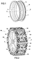
- the figure 1 shows a perspective view of a fan casing 10 which can be manufactured using a mold and a method according to the invention.
- a casing is centered on a longitudinal axis XX and comprises an annular wall 11 delimited upstream by an upstream flange 12 and downstream by a downstream flange 3 (the upstream and downstream being defined relative to the direction gas flow in the gas turbine).
- the internal surface 14 of the annular wall 11 is intended to delimit the air intake stream in the gas turbine.
- the figure 2 is a schematic perspective view of a mold according to the invention when it is closed.
- Such a mold can be used for the impregnation by a process of the RTM (“Resin Transfer Molding”) type of a fibrous preform in order to manufacture a fan casing 10 such as that presented above.
- the fibrous preform can be produced by three-dimensional weaving of fibers, for example carbon, glass, aramid or ceramic, and the impregnation matrix can be made of polymer, for example epoxide, bismaleimide or polyimimde.
- the mold 100 is rotatably mounted on a drive axis (not shown) centered on the axis XX, and comprises a mandrel 120. Thereafter, the longitudinal, transverse and radial directions will be defined relative to this axis XX , a transverse plane being a plane perpendicular to the longitudinal axis.
- the mandrel 120 comprises an annular wall 121 taking the form of a barrel on which is intended to be wound a fibrous preform 200 ( figure 5 ), and two lateral flanges 122.
- the mandrel 120 is held on its drive axis by means of six spokes 110.
- the flanges 122 form a support intended to receive the folded parts of the preform 200 wound on the mandrel 120, and which are intended to form the upstream 12 and downstream 13 flanges of the fan casing 10.
- the mold 100 further comprises a counter-mold composed of several angular sectors of the counter-mold 130 (here six in number) assembled in a sealed manner on the mandrel 120, and locked together in a sealed manner by as many locking keys 140.
- the sectors 130 are assembled on the lateral flanges 122 by clamping screws 131 which extend along a radial axis.
- the sectors 130 are fixed mechanically and directly to the mandrel 120. These screws 131 allow the sectors 130 to be assembled on the flanges 122 and the adjustment of the compaction pressure which is applied to the fiber preform 200.
- O-rings (not shown) ) positioned on the flanges 122 seal between the sectors 130 and the mandrel 120.
- each locking key 140 is fixed directly on two neighboring sectors 130.
- the keys ensure a circumferential tightening of the sectors 130 between them, and a seal between these sectors thanks to flat seals (not shown) positioned between the sectors 130. It will be noted that the keys 140 play no role. in the assembly of the sectors 130 on the mandrel 120.
- a fibrous preform 200 ( figure 3 ) must first be wound on the mandrel 120.
- Methods have already been proposed for winding a fibrous preform produced for example by three-dimensional weaving around a mandrel such as that of the invention, and will not be described further. detail.
- the sectors 130 must be assembled on the mandrel 120.
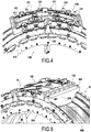
- the figure 4 shows a step of approaching a sector 130 on the mandrel 120.
- guide means 123, 132 are provided to ensure that the sector 130 approaches the mandrel radially and compacts the preform 200 in a radial direction on the mandrel 120.
- These guide means comprise fingers 123 extending along a radial axis provided on each flange 122, these fingers 123 being intended to cooperate with grooves 132 of shape complementary to that of the fingers 123 also extending along a radial axis and provided centered on the upstream and downstream faces of each sector 130.
- the fingers 123 may be present on the upstream and downstream faces of each sector 130, and the grooves 132 may be present on the flanges 122.
- the clamping screws 131 are positioned to finalize the tight assembly of the sector 130 on the mandrel.
- the compaction pressure of the preform 200 can be controlled and maintained by these clamping screws 131.
- the clamping screws 131 are preferably placed in a certain order, starting with those closest to the guide finger 123, and ending with those located at the ends of sector 130.
- the sectors 130 are assembled on the mandrel 120 in a certain order: the sectors designated A, C and E are positioned first, then the sectors B, D and F.
- the sector A is positioned at the level of the end of winding of the preform. It is important to mount the sectors in this order to avoid the formation of warped in the fibrous preform 200 when the mold is closed.
- two compacting blocks 300 are temporarily fixed (only one is shown on the figure 5 ) on the mandrel 120 in the space which will be occupied by sectors B, D and F.
- These shims are used mainly to prevent the last three sectors B, D and F from pinching the fibrous preform at the interface between two sectors 130 at the time of their assembly on the mandrel 120.
- a compaction block 300 ( figure 5 ) is temporarily positioned against the longitudinal face 133 of sector A, and another wedge 300 will be positioned against the longitudinal face 133 of sector C (not shown in the figure 5 ).
- These wedges 300 are fixed to the flanges 122 of the mandrel 120 by screws 301, and are intended to compact the preform 200 on an uncompacted portion thereof.
- each compaction wedge 300 is brought towards the mandrel 120 along the face 133 of the neighboring sector 130, in the direction indicated by the arrow 302 (unlike the sectors 130 which are brought radially onto the mandrel 120). Consequently, pinching of the fibrous preform 200 is avoided, and the transition between the region compacted by the neighboring sector and the non-compacted region is displaced.
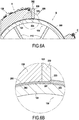
- the figure 6B shows an enlarged view of the figure 6A at the base of the compaction wedge 300.
- the compaction wedge 300 comprises a face 303 which compacts the preform 200 and has a profile configured to create a compaction transition zone 201 between a part 202 compacted by a sector 130 (here sector A) and a non-compacted part 203 of the preform (corresponding to the location of sector B).
- the profile is rounded at the end of the wedge opposite the face 133 of the sector 130 against which the wedge 300 is positioned. It will then be understood that the preform 200 is compacted by the wedges 300 at the interface between the sectors A and B, and, B and C.
- the compacting transition zone 201 will be compacted by the sector B when it is assembled on the mandrel 120, without generating pinching of the preform 200.
- the shims 300 must be held on the mandrel for a few minutes, and the last sectors B, D and F must be assembled quickly after the disassembly of the shims 300 so that the preform is still compacted at the shims 300 and that pinching is avoided. .
- the locking keys 140 are put in place between the neighboring sectors 130 to complete the closing of the mold.
- a polymerizable resin is then injected into the mold 100 by a pressure differential (by a process of the RTM type), and the latter is polymerized (by heating or cooling for example, depending on the nature of the resin used).
- the fan casing 10 thus produced can then be removed from the mold.
Landscapes
- Engineering & Computer Science (AREA)
- Mechanical Engineering (AREA)
- Chemical & Material Sciences (AREA)
- Composite Materials (AREA)
- Moulding By Coating Moulds (AREA)
- Structures Of Non-Positive Displacement Pumps (AREA)
Claims (11)
- Form (100) zur Verwendung bei der Herstellung eines Gebläsegehäuses (10) einer Gasturbine aus Verbundwerkstoff, umfassend:- einen Dorn (120), auf den ein Faservorformling (200) des Gebläsegehäuses gewickelt werden soll, umfassend eine ringförmige Wand (121), deren Außenflächenprofil dem Profil der Innenfläche (14) des herzustellenden Gehäuses entspricht, sowie zwei seitliche Flansche (122), deren Profile denjenigen von Außenflanschen (12, 13) des herzustellenden Gehäuses entsprechen,- eine Vielzahl von Gegenform-Winkelsektoren (130), die an dem Dorn dicht montiert und dazu bestimmt sind, die Form zu schließen und einen auf den Dorn gewickelten Faservorformling (200) zu verdichten, und- eine Vielzahl von Verriegelungsschlüsseln (140), die dazu ausgelegt sind, die benachbarten Gegenform-Sektoren dicht untereinander zu verriegeln, wobei jeder Verriegelungsschlüssel an zwei benachbarten Gegenform-Winkelsektoren befestigt ist.
- Form nach Anspruch 1, ferner umfassend Führungsmittel (123, 132), die dazu bestimmt sind, jeden Gegenform-Sektor bei seiner Montage an dem Dorn der Form zu führen.
- Form nach Anspruch 2, bei der die Führungsmittel eine Vielzahl von Fingern (123) umfassen, die sich von einem seitlichen Flansch (122) des Dorns (120) ausgehend entlang einer radialen Achse erstrecken, wobei jeder Finger mit einer Nut (132), welche an jedem Gegenform-Sektor vorhanden ist, zusammenwirkt, oder bei der die Führungsmittel eine Vielzahl von Fingern umfassen, die sich entlang einer radialen Achse erstrecken und auf den stromaufwärtigen und stromabwärtigen Seiten eines jeden Gegenform-Sektors (130) vorhanden sind, wobei jeder Finger mit einer an einem seitlichen Flansch (122) des Dorns vorhandenen Nut zusammenwirkt.
- Form nach einem der Ansprüche 1 bis 3, ferner umfassend eine Vielzahl von Klemmschrauben (131), die sich entlang radialer Achsen erstrecken und dazu ausgelegt sind, die Gegenform-Sektoren an dem Dorn der Form zu befestigen.
- Form nach einem der Ansprüche 1 bis 4, die sechs Winkelsektoren (130) und sechs Verriegelungsschlüssel (140) umfasst.
- Verfahren zum Schließen einer Spritzgussform (100) nach Anspruch 1, die zur Verwendung bei der Herstellung eines Gebläsegehäuses (10) einer Gasturbine aus Verbundwerkstoff bestimmt ist, wobei die Form einen Dorn (120) umfasst, auf den ein Faservorformling (200) des Gebläsegehäuses gewickelt werden soll, wobei der Dorn eine ringförmige Wand (121), deren Außenflächenprofil dem Profil der Innenfläche (14) des herzustellenden Gehäuses entspricht, sowie zwei seitliche Flansche (122) umfasst, deren Profile denjenigen von Außenflanschen (12, 13) des herzustellenden Gehäuses entsprechen, wobei die Form ferner eine Vielzahl von Gegenform-Winkelsektoren (130) umfasst, die dazu bestimmt sind, die Form zu schließen und den auf den Dorn gewickelten Faservorformling zu verdichten, wobei das Verfahren umfasst:a) das dichte Montieren der Gegenform-Sektoren an dem Dorn der Form undb) das Befestigen eines Verriegelungsschlüssels an zwei benachbarten Gegenform-Winkelsektoren, um ein dichtes Verriegeln der benachbarten Winkelsektoren untereinander sicherzustellen.
- Verfahren nach Anspruch 6, bei dem die Form wenigstens drei Gegenform-Sektoren umfasst, wobei Schritt a) umfasst:- das dichte Montieren eines ersten und eines zweiten Gegenform-Sektors an dem Dorn der Form unter Freilassen eines Raumes zwischen ihnen, welcher dazu bestimmt ist, einen dritten Gegenform-Sektor aufzunehmen,- das vorübergehende Befestigen wenigstens eines Verdichtungskeils (300) an dem Dorn (120) in dem Raum, der zur Aufnahme des dritten Gegenform-Sektors bestimmt ist, wobei der Verdichtungskeil an einer Längsseite (133) des ersten oder des zweiten Gegenform-Sektors positioniert und dazu bestimmt ist, einen Teil (201) des Vorformlings zu verdichten.
- Verfahren nach Anspruch 7, bei dem der Verdichtungskeil (300) eine Seite (303) umfasst, die dazu bestimmt ist, den Vorformling (200) zu verdichten, wobei die Seite ein Profil aufweist, das dazu ausgelegt ist, einen Verdichtungsübergangsbereich (201) zwischen einem Teil (202) des Vorformlings, der durch einen Gegenform-Sektor verdichtet ist, und einem nicht verdichteten Teil (203) des Vorformlings zu erzeugen.
- Verfahren nach Anspruch 8, bei dem die Seite (303) des Verdichtungskeils, die dazu bestimmt ist, den Vorformling zu verdichten, im Bereich ihres Endes, das der Längsseite (133) des Gegenform-Sektors (130), an welcher der Verdichtungskeil positioniert ist, gegenüberliegt, ein abgerundetes Profil aufweist.
- Verfahren zur Herstellung eines Gasturbinen-Gebläsegehäuses aus Verbundwerkstoff, umfassend:- das Aufwickeln eines Faservorformlings (200) auf den Dorn (120) einer Form (100) nach einem der Ansprüche 1 bis 5,- das Schließen der Form durch ein Verfahren nach einem der Ansprüche 6 bis 9,- das Einspritzen eines Harzes in die Form und- das Ausformen des Gebläsegehäuses (10).
- Verfahren zur Herstellung einer Gasturbine, welches die Schritte des Verfahrens zur Herstellung eines Gasturbinen-Gebläsegehäuses (10) aus Verbundwerkstoff nach Anspruch 10 umfasst.
Applications Claiming Priority (2)
| Application Number | Priority Date | Filing Date | Title |
|---|---|---|---|
| FR1561396A FR3044253B1 (fr) | 2015-11-26 | 2015-11-26 | Moule pour la fabrication d'un carter de soufflante de turbine a gaz en materiau composite et procede de fermeture d'un tel moule |
| PCT/FR2016/052987 WO2017089680A1 (fr) | 2015-11-26 | 2016-11-17 | Moule pour la fabrication d'un carter de soufflante de turbine a gaz en materiau composite et procede de fermeture d'un tel moule |
Publications (2)
| Publication Number | Publication Date |
|---|---|
| EP3380294A1 EP3380294A1 (de) | 2018-10-03 |
| EP3380294B1 true EP3380294B1 (de) | 2020-07-08 |
Family
ID=55300573
Family Applications (1)
| Application Number | Title | Priority Date | Filing Date |
|---|---|---|---|
| EP16815580.2A Active EP3380294B1 (de) | 2015-11-26 | 2016-11-17 | Form zur herstellung eines aus verbundstoffmaterial hergestellten gasturbinengebläsegehäuses und verfahren zum schliessen solch einer form |
Country Status (5)
| Country | Link |
|---|---|
| US (1) | US10737407B2 (de) |
| EP (1) | EP3380294B1 (de) |
| CN (1) | CN108367462B (de) |
| FR (1) | FR3044253B1 (de) |
| WO (1) | WO2017089680A1 (de) |
Families Citing this family (13)
| Publication number | Priority date | Publication date | Assignee | Title |
|---|---|---|---|---|
| US11400624B2 (en) * | 2018-09-24 | 2022-08-02 | Raytheon Technologies Corporation | Constant cross section mandrel for CMC components |
| US12304115B2 (en) * | 2019-07-11 | 2025-05-20 | Textron Innovations Inc. | Tooling method for molding composite ducts |
| FR3100737B1 (fr) | 2019-09-12 | 2021-08-20 | Safran Aircraft Engines | Procédé de fermeture d’un moule d’injection utilisant des plis sacrificiels anti-pincement |
| FR3100738B1 (fr) | 2019-09-12 | 2021-08-20 | Safran Aircraft Engines | Procédé de fermeture d’un moule d’injection utilisant des feuillards anti-pincement |
| FR3108867B1 (fr) | 2020-04-07 | 2022-04-15 | Safran Aircraft Engines | Moule pour la fabrication d’un carter de soufflante de turbomachine en matériau composite |
| US12325156B2 (en) * | 2020-04-10 | 2025-06-10 | Safran Aircraft Engines | Mold for manufacturing a turbine engine fan casing from a composite material |
| CN115697682B (zh) * | 2020-06-04 | 2026-06-19 | 赛峰航空器发动机 | 使用对称的抗挤压扇段的rtm注射方法和模具 |
| US11648739B2 (en) * | 2020-06-04 | 2023-05-16 | Safran Aircraft Engines | Rtm injection mold and method using asymmetric anti-pinching sectors |
| FR3114043B1 (fr) * | 2020-09-16 | 2022-09-09 | Safran Aircraft Engines | Moule pour la fabrication d’un carter de soufflante de turbomachine en matériau composite à dilatation différentielle |
| FR3125247B1 (fr) * | 2021-07-16 | 2024-03-29 | Safran Aircraft Engines | Fabrication d’un carter composite pour une turbomachine d’aeronef |
| FR3126916B1 (fr) * | 2021-09-16 | 2024-05-10 | Safran Aircraft Engines | Cale de compactage d’un moule de carter de soufflante |
| CN118354890A (zh) * | 2021-11-09 | 2024-07-16 | 赛峰飞机发动机公司 | 在缠绕机的浸渍心轴注射树脂的方法和保持纤维织物的装置 |
| CN115139393B (zh) * | 2022-06-21 | 2024-08-30 | 西安鑫垚陶瓷复合材料股份有限公司 | 一种2.5d涡轮外环预制体定型模具及其使用方法 |
Family Cites Families (12)
| Publication number | Priority date | Publication date | Assignee | Title |
|---|---|---|---|---|
| US4288277A (en) * | 1979-07-17 | 1981-09-08 | Lembit Siilats | Molding system with retracting mold |
| US7335012B2 (en) * | 2004-12-22 | 2008-02-26 | General Electric Company | Apparatus for fabricating reinforced composite materials |
| US7571527B2 (en) * | 2005-03-29 | 2009-08-11 | The Boeing Company | Mandrel for fabrication of a monolithic composite nacelle panel |
| US7707708B2 (en) * | 2005-09-21 | 2010-05-04 | Rohr, Inc. | Apparatus for making a tubular composite structure |
| US8052823B2 (en) * | 2008-01-31 | 2011-11-08 | Alliant Techsystems Inc. | Stiffener tool positioning apparatus |
| US8025499B2 (en) * | 2008-11-03 | 2011-09-27 | Rohr, Inc. | Multi-segment tool and method for composite formation |
| FR2957093B1 (fr) * | 2010-03-02 | 2012-03-23 | Snecma | Preforme fibreuse pour un secteur d'anneau de turbine et son procede de fabrication. |
| FR2974027B1 (fr) * | 2011-04-13 | 2014-09-26 | Snecma | Dispositif de compactage pour machine d'enroulement d'une texture fibreuse sur un mandrin d'impregnation |
| FR2981881B1 (fr) * | 2011-10-26 | 2013-12-13 | Snecma | Dispositif de maintien d'une texture fibreuse sur un mandrin d'impregnation d'une machine d'enroulement |
| FR2995555B1 (fr) * | 2012-09-17 | 2017-11-24 | Snecma | Machine d'enroulement d'une texture fibreuse permettant un controle d'alignement et de decadrage par analyse d'image |
| FR3002750B1 (fr) * | 2013-03-01 | 2015-04-10 | Safran | Moule d'injection pour la fabrication d'une piece de revolution en materiau composite ayant des brides externes, et notamment d'un carter de turbine a gaz |
| FR3026674B1 (fr) * | 2014-10-07 | 2017-03-31 | Snecma | Procede de demoulage d'un materiau composite a matrice organique |
-
2015
- 2015-11-26 FR FR1561396A patent/FR3044253B1/fr not_active Expired - Fee Related
-
2016
- 2016-11-17 US US15/777,713 patent/US10737407B2/en active Active
- 2016-11-17 CN CN201680068090.5A patent/CN108367462B/zh active Active
- 2016-11-17 EP EP16815580.2A patent/EP3380294B1/de active Active
- 2016-11-17 WO PCT/FR2016/052987 patent/WO2017089680A1/fr not_active Ceased
Non-Patent Citations (1)
| Title |
|---|
| None * |
Also Published As
| Publication number | Publication date |
|---|---|
| WO2017089680A1 (fr) | 2017-06-01 |
| US20180370082A1 (en) | 2018-12-27 |
| FR3044253B1 (fr) | 2018-05-18 |
| CN108367462B (zh) | 2020-12-04 |
| CN108367462A (zh) | 2018-08-03 |
| US10737407B2 (en) | 2020-08-11 |
| FR3044253A1 (fr) | 2017-06-02 |
| EP3380294A1 (de) | 2018-10-03 |
Similar Documents
| Publication | Publication Date | Title |
|---|---|---|
| WO2017089680A1 (fr) | Moule pour la fabrication d'un carter de soufflante de turbine a gaz en materiau composite et procede de fermeture d'un tel moule | |
| EP2961590B1 (de) | Spritzgiesswerkzeug zur herstellung eines rotierenden teils aus einem verbundstoff mit externen flanschen, insbesondere für ein gasturbinengehäuse | |
| EP2077183B1 (de) | Verbundflansch mit Verarbeitungsteil | |
| EP4401954B1 (de) | Kompaktierungsblock für eine lüftergehäuseform | |
| EP4028249A1 (de) | Verfahren zum schliessen einer spritzgiessform mittels einklemmschutzbändern | |
| EP2763841B1 (de) | Vorrichtung und verfahren zur herstellung eines teils aus einem verbundwerkstoff | |
| BE1025628B1 (fr) | Procédé de fabrication de carter composite de compresseur pour turbomachine | |
| EP2560808A1 (de) | Vorrichtung zur herstellung eines gehäuses aus verbundstoff und herstellungsverfahren mit einer derartigen vorrichtung | |
| FR3031469A1 (fr) | Carter en materiau composite a matrice organique auto-raidi | |
| EP2707199A1 (de) | Verdichtungs- und spritzgiessform für faservorformling zur herstellung einer turbomaschinen- gleichrichterschaufel aus verbundstoff | |
| EP2771174A1 (de) | Imprägnierungsdorn mit einem vakuumbeutel zur herstellung eines gasturbinengehäuses aus verbundwerkstoff | |
| FR3026674A1 (fr) | Procede de demoulage d'un materiau composite a matrice organique | |
| EP4132760B1 (de) | Form zur herstellung eines turbinenmotorgebläsegehäuses aus einem verbundstoffmaterial | |
| EP3402657A1 (de) | Vorrichtung zum führen einer faserigen struktur auf einen imprägnierdorn und zugehöriger imprägnierdorn und wickelmaschine | |
| EP4133163B1 (de) | Form zur herstellung eines turbinenmotorgebläsegehäuses aus einem verbundstoffmaterial | |
| FR3100737A1 (fr) | Procédé de fermeture d’un moule d’injection utilisant des plis sacrificiels anti-pincement | |
| EP4161762B1 (de) | Form und verfahren zur rtm injektion mit symetrische anti-quetschung sektoren | |
| FR3146615A1 (fr) | Moule d’injection pour préforme fibreuse avec contre-moules ajustables | |
| FR3146614A1 (fr) | Cale de compactage ajustable pour compenser l’usure des moules | |
| FR3154342A1 (fr) | Moule destiné à être utilisé pour la fabrication d'un carter de soufflante et procédé de fabrication d’un carter de soufflante |
Legal Events
| Date | Code | Title | Description |
|---|---|---|---|
| STAA | Information on the status of an ep patent application or granted ep patent |
Free format text: STATUS: UNKNOWN |
|
| STAA | Information on the status of an ep patent application or granted ep patent |
Free format text: STATUS: THE INTERNATIONAL PUBLICATION HAS BEEN MADE |
|
| PUAI | Public reference made under article 153(3) epc to a published international application that has entered the european phase |
Free format text: ORIGINAL CODE: 0009012 |
|
| STAA | Information on the status of an ep patent application or granted ep patent |
Free format text: STATUS: REQUEST FOR EXAMINATION WAS MADE |
|
| 17P | Request for examination filed |
Effective date: 20180503 |
|
| AK | Designated contracting states |
Kind code of ref document: A1 Designated state(s): AL AT BE BG CH CY CZ DE DK EE ES FI FR GB GR HR HU IE IS IT LI LT LU LV MC MK MT NL NO PL PT RO RS SE SI SK SM TR |
|
| AX | Request for extension of the european patent |
Extension state: BA ME |
|
| DAV | Request for validation of the european patent (deleted) | ||
| DAX | Request for extension of the european patent (deleted) | ||
| STAA | Information on the status of an ep patent application or granted ep patent |
Free format text: STATUS: EXAMINATION IS IN PROGRESS |
|
| 17Q | First examination report despatched |
Effective date: 20191024 |
|
| GRAP | Despatch of communication of intention to grant a patent |
Free format text: ORIGINAL CODE: EPIDOSNIGR1 |
|
| STAA | Information on the status of an ep patent application or granted ep patent |
Free format text: STATUS: GRANT OF PATENT IS INTENDED |
|
| INTG | Intention to grant announced |
Effective date: 20200226 |
|
| GRAS | Grant fee paid |
Free format text: ORIGINAL CODE: EPIDOSNIGR3 |
|
| GRAA | (expected) grant |
Free format text: ORIGINAL CODE: 0009210 |
|
| STAA | Information on the status of an ep patent application or granted ep patent |
Free format text: STATUS: THE PATENT HAS BEEN GRANTED |
|
| AK | Designated contracting states |
Kind code of ref document: B1 Designated state(s): AL AT BE BG CH CY CZ DE DK EE ES FI FR GB GR HR HU IE IS IT LI LT LU LV MC MK MT NL NO PL PT RO RS SE SI SK SM TR |
|
| REG | Reference to a national code |
Ref country code: CH Ref legal event code: EP Ref country code: AT Ref legal event code: REF Ref document number: 1287967 Country of ref document: AT Kind code of ref document: T Effective date: 20200715 |
|
| REG | Reference to a national code |
Ref country code: DE Ref legal event code: R096 Ref document number: 602016039669 Country of ref document: DE |
|
| REG | Reference to a national code |
Ref country code: IE Ref legal event code: FG4D Free format text: LANGUAGE OF EP DOCUMENT: FRENCH |
|
| REG | Reference to a national code |
Ref country code: SE Ref legal event code: TRGR |
|
| REG | Reference to a national code |
Ref country code: LT Ref legal event code: MG4D |
|
| REG | Reference to a national code |
Ref country code: AT Ref legal event code: MK05 Ref document number: 1287967 Country of ref document: AT Kind code of ref document: T Effective date: 20200708 |
|
| REG | Reference to a national code |
Ref country code: NL Ref legal event code: MP Effective date: 20200708 |
|
| PG25 | Lapsed in a contracting state [announced via postgrant information from national office to epo] |
Ref country code: FI Free format text: LAPSE BECAUSE OF FAILURE TO SUBMIT A TRANSLATION OF THE DESCRIPTION OR TO PAY THE FEE WITHIN THE PRESCRIBED TIME-LIMIT Effective date: 20200708 Ref country code: NO Free format text: LAPSE BECAUSE OF FAILURE TO SUBMIT A TRANSLATION OF THE DESCRIPTION OR TO PAY THE FEE WITHIN THE PRESCRIBED TIME-LIMIT Effective date: 20201008 Ref country code: AT Free format text: LAPSE BECAUSE OF FAILURE TO SUBMIT A TRANSLATION OF THE DESCRIPTION OR TO PAY THE FEE WITHIN THE PRESCRIBED TIME-LIMIT Effective date: 20200708 Ref country code: PT Free format text: LAPSE BECAUSE OF FAILURE TO SUBMIT A TRANSLATION OF THE DESCRIPTION OR TO PAY THE FEE WITHIN THE PRESCRIBED TIME-LIMIT Effective date: 20201109 Ref country code: HR Free format text: LAPSE BECAUSE OF FAILURE TO SUBMIT A TRANSLATION OF THE DESCRIPTION OR TO PAY THE FEE WITHIN THE PRESCRIBED TIME-LIMIT Effective date: 20200708 Ref country code: BG Free format text: LAPSE BECAUSE OF FAILURE TO SUBMIT A TRANSLATION OF THE DESCRIPTION OR TO PAY THE FEE WITHIN THE PRESCRIBED TIME-LIMIT Effective date: 20201008 Ref country code: GR Free format text: LAPSE BECAUSE OF FAILURE TO SUBMIT A TRANSLATION OF THE DESCRIPTION OR TO PAY THE FEE WITHIN THE PRESCRIBED TIME-LIMIT Effective date: 20201009 Ref country code: ES Free format text: LAPSE BECAUSE OF FAILURE TO SUBMIT A TRANSLATION OF THE DESCRIPTION OR TO PAY THE FEE WITHIN THE PRESCRIBED TIME-LIMIT Effective date: 20200708 Ref country code: LT Free format text: LAPSE BECAUSE OF FAILURE TO SUBMIT A TRANSLATION OF THE DESCRIPTION OR TO PAY THE FEE WITHIN THE PRESCRIBED TIME-LIMIT Effective date: 20200708 |
|
| PG25 | Lapsed in a contracting state [announced via postgrant information from national office to epo] |
Ref country code: LV Free format text: LAPSE BECAUSE OF FAILURE TO SUBMIT A TRANSLATION OF THE DESCRIPTION OR TO PAY THE FEE WITHIN THE PRESCRIBED TIME-LIMIT Effective date: 20200708 Ref country code: PL Free format text: LAPSE BECAUSE OF FAILURE TO SUBMIT A TRANSLATION OF THE DESCRIPTION OR TO PAY THE FEE WITHIN THE PRESCRIBED TIME-LIMIT Effective date: 20200708 Ref country code: RS Free format text: LAPSE BECAUSE OF FAILURE TO SUBMIT A TRANSLATION OF THE DESCRIPTION OR TO PAY THE FEE WITHIN THE PRESCRIBED TIME-LIMIT Effective date: 20200708 Ref country code: IS Free format text: LAPSE BECAUSE OF FAILURE TO SUBMIT A TRANSLATION OF THE DESCRIPTION OR TO PAY THE FEE WITHIN THE PRESCRIBED TIME-LIMIT Effective date: 20201108 |
|
| PG25 | Lapsed in a contracting state [announced via postgrant information from national office to epo] |
Ref country code: NL Free format text: LAPSE BECAUSE OF FAILURE TO SUBMIT A TRANSLATION OF THE DESCRIPTION OR TO PAY THE FEE WITHIN THE PRESCRIBED TIME-LIMIT Effective date: 20200708 |
|
| REG | Reference to a national code |
Ref country code: DE Ref legal event code: R097 Ref document number: 602016039669 Country of ref document: DE |
|
| PG25 | Lapsed in a contracting state [announced via postgrant information from national office to epo] |
Ref country code: EE Free format text: LAPSE BECAUSE OF FAILURE TO SUBMIT A TRANSLATION OF THE DESCRIPTION OR TO PAY THE FEE WITHIN THE PRESCRIBED TIME-LIMIT Effective date: 20200708 Ref country code: SM Free format text: LAPSE BECAUSE OF FAILURE TO SUBMIT A TRANSLATION OF THE DESCRIPTION OR TO PAY THE FEE WITHIN THE PRESCRIBED TIME-LIMIT Effective date: 20200708 Ref country code: RO Free format text: LAPSE BECAUSE OF FAILURE TO SUBMIT A TRANSLATION OF THE DESCRIPTION OR TO PAY THE FEE WITHIN THE PRESCRIBED TIME-LIMIT Effective date: 20200708 Ref country code: DK Free format text: LAPSE BECAUSE OF FAILURE TO SUBMIT A TRANSLATION OF THE DESCRIPTION OR TO PAY THE FEE WITHIN THE PRESCRIBED TIME-LIMIT Effective date: 20200708 Ref country code: CZ Free format text: LAPSE BECAUSE OF FAILURE TO SUBMIT A TRANSLATION OF THE DESCRIPTION OR TO PAY THE FEE WITHIN THE PRESCRIBED TIME-LIMIT Effective date: 20200708 |
|
| PLBE | No opposition filed within time limit |
Free format text: ORIGINAL CODE: 0009261 |
|
| STAA | Information on the status of an ep patent application or granted ep patent |
Free format text: STATUS: NO OPPOSITION FILED WITHIN TIME LIMIT |
|
| PG25 | Lapsed in a contracting state [announced via postgrant information from national office to epo] |
Ref country code: AL Free format text: LAPSE BECAUSE OF FAILURE TO SUBMIT A TRANSLATION OF THE DESCRIPTION OR TO PAY THE FEE WITHIN THE PRESCRIBED TIME-LIMIT Effective date: 20200708 |
|
| 26N | No opposition filed |
Effective date: 20210409 |
|
| PG25 | Lapsed in a contracting state [announced via postgrant information from national office to epo] |
Ref country code: MC Free format text: LAPSE BECAUSE OF FAILURE TO SUBMIT A TRANSLATION OF THE DESCRIPTION OR TO PAY THE FEE WITHIN THE PRESCRIBED TIME-LIMIT Effective date: 20200708 Ref country code: SK Free format text: LAPSE BECAUSE OF FAILURE TO SUBMIT A TRANSLATION OF THE DESCRIPTION OR TO PAY THE FEE WITHIN THE PRESCRIBED TIME-LIMIT Effective date: 20200708 |
|
| REG | Reference to a national code |
Ref country code: CH Ref legal event code: PL |
|
| PG25 | Lapsed in a contracting state [announced via postgrant information from national office to epo] |
Ref country code: LU Free format text: LAPSE BECAUSE OF NON-PAYMENT OF DUE FEES Effective date: 20201117 |
|
| REG | Reference to a national code |
Ref country code: BE Ref legal event code: MM Effective date: 20201130 |
|
| PG25 | Lapsed in a contracting state [announced via postgrant information from national office to epo] |
Ref country code: CH Free format text: LAPSE BECAUSE OF NON-PAYMENT OF DUE FEES Effective date: 20201130 Ref country code: SI Free format text: LAPSE BECAUSE OF FAILURE TO SUBMIT A TRANSLATION OF THE DESCRIPTION OR TO PAY THE FEE WITHIN THE PRESCRIBED TIME-LIMIT Effective date: 20200708 Ref country code: LI Free format text: LAPSE BECAUSE OF NON-PAYMENT OF DUE FEES Effective date: 20201130 |
|
| PG25 | Lapsed in a contracting state [announced via postgrant information from national office to epo] |
Ref country code: IE Free format text: LAPSE BECAUSE OF NON-PAYMENT OF DUE FEES Effective date: 20201117 |
|
| PG25 | Lapsed in a contracting state [announced via postgrant information from national office to epo] |
Ref country code: TR Free format text: LAPSE BECAUSE OF FAILURE TO SUBMIT A TRANSLATION OF THE DESCRIPTION OR TO PAY THE FEE WITHIN THE PRESCRIBED TIME-LIMIT Effective date: 20200708 Ref country code: MT Free format text: LAPSE BECAUSE OF FAILURE TO SUBMIT A TRANSLATION OF THE DESCRIPTION OR TO PAY THE FEE WITHIN THE PRESCRIBED TIME-LIMIT Effective date: 20200708 Ref country code: CY Free format text: LAPSE BECAUSE OF FAILURE TO SUBMIT A TRANSLATION OF THE DESCRIPTION OR TO PAY THE FEE WITHIN THE PRESCRIBED TIME-LIMIT Effective date: 20200708 |
|
| PG25 | Lapsed in a contracting state [announced via postgrant information from national office to epo] |
Ref country code: MK Free format text: LAPSE BECAUSE OF FAILURE TO SUBMIT A TRANSLATION OF THE DESCRIPTION OR TO PAY THE FEE WITHIN THE PRESCRIBED TIME-LIMIT Effective date: 20200708 |
|
| PG25 | Lapsed in a contracting state [announced via postgrant information from national office to epo] |
Ref country code: BE Free format text: LAPSE BECAUSE OF NON-PAYMENT OF DUE FEES Effective date: 20201130 |
|
| PGFP | Annual fee paid to national office [announced via postgrant information from national office to epo] |
Ref country code: DE Payment date: 20251118 Year of fee payment: 10 |
|
| PGFP | Annual fee paid to national office [announced via postgrant information from national office to epo] |
Ref country code: GB Payment date: 20251125 Year of fee payment: 10 |
|
| PGFP | Annual fee paid to national office [announced via postgrant information from national office to epo] |
Ref country code: IT Payment date: 20251128 Year of fee payment: 10 |
|
| PGFP | Annual fee paid to national office [announced via postgrant information from national office to epo] |
Ref country code: FR Payment date: 20251125 Year of fee payment: 10 |
|
| PGFP | Annual fee paid to national office [announced via postgrant information from national office to epo] |
Ref country code: SE Payment date: 20251119 Year of fee payment: 10 |