EP3380367B1 - Kraftfahrzeug mit einer schutzeinrichtung für den fahrerkopf - Google Patents
Kraftfahrzeug mit einer schutzeinrichtung für den fahrerkopf Download PDFInfo
- Publication number
- EP3380367B1 EP3380367B1 EP16805027.6A EP16805027A EP3380367B1 EP 3380367 B1 EP3380367 B1 EP 3380367B1 EP 16805027 A EP16805027 A EP 16805027A EP 3380367 B1 EP3380367 B1 EP 3380367B1
- Authority
- EP
- European Patent Office
- Prior art keywords
- vehicle
- anchor point
- protection
- protection member
- pilot
- Prior art date
- Legal status (The legal status is an assumption and is not a legal conclusion. Google has not performed a legal analysis and makes no representation as to the accuracy of the status listed.)
- Active
Links
Images

Classifications
-
- B—PERFORMING OPERATIONS; TRANSPORTING
- B60—VEHICLES IN GENERAL
- B60R—VEHICLES, VEHICLE FITTINGS, OR VEHICLE PARTS, NOT OTHERWISE PROVIDED FOR
- B60R21/00—Arrangements or fittings on vehicles for protecting or preventing injuries to occupants or pedestrians in case of accidents or other traffic risks
-
- B—PERFORMING OPERATIONS; TRANSPORTING
- B60—VEHICLES IN GENERAL
- B60R—VEHICLES, VEHICLE FITTINGS, OR VEHICLE PARTS, NOT OTHERWISE PROVIDED FOR
- B60R21/00—Arrangements or fittings on vehicles for protecting or preventing injuries to occupants or pedestrians in case of accidents or other traffic risks
- B60R21/02—Occupant safety arrangements or fittings, e.g. crash pads
-
- B—PERFORMING OPERATIONS; TRANSPORTING
- B60—VEHICLES IN GENERAL
- B60R—VEHICLES, VEHICLE FITTINGS, OR VEHICLE PARTS, NOT OTHERWISE PROVIDED FOR
- B60R21/00—Arrangements or fittings on vehicles for protecting or preventing injuries to occupants or pedestrians in case of accidents or other traffic risks
- B60R2021/003—Arrangements or fittings on vehicles for protecting or preventing injuries to occupants or pedestrians in case of accidents or other traffic risks characterised by occupant or pedestian
- B60R2021/0039—Body parts of the occupant or pedestrian affected by the accident
- B60R2021/0048—Head
-
- B—PERFORMING OPERATIONS; TRANSPORTING
- B60—VEHICLES IN GENERAL
- B60R—VEHICLES, VEHICLE FITTINGS, OR VEHICLE PARTS, NOT OTHERWISE PROVIDED FOR
- B60R21/00—Arrangements or fittings on vehicles for protecting or preventing injuries to occupants or pedestrians in case of accidents or other traffic risks
- B60R2021/0065—Type of vehicles
- B60R2021/0086—Racing cars
Definitions
- the present invention relates to the field of motor racing and relates more particularly to a motor vehicle comprising an open cockpit and a member for protecting the head of the driver of the vehicle.
- a motor vehicle for racing such as a Formula 1 or Indycar car, comprises a carbon chassis in which the cockpit is located.
- a motor vehicle comprising a structural chassis extending longitudinally from rear to front and an open cockpit, the structural chassis comprising an opening allowing a driver of the vehicle to access the open cockpit, the vehicle comprising a protective member positioned above the cockpit and configured to protect the pilot's head, the protective member being mounted integrally with the structural chassis.
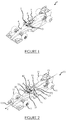
- a driver P of vehicle 1 accesses the cockpit 2 through an upper opening 3 of the chassis 4 and the head of the driver P protrudes from the chassis 4 through this opening 3 when he is driving the vehicle 1.
- Such a cockpit 2 is says "open”. Pilot P's head is then exposed to impact in the event of an accident, which can lead to serious injuries.
- the chassis 4 comprises, in a known manner, a rear protection device 5, known to those skilled in the art under the name of "rear roll bar", rising higher than the head of the pilot P in order to protect the pilot P in the event of the vehicle overturning 1 and allow its extraction from the cockpit 2.
- a rear protection device 5 does not make it possible to protect the head of the pilot P from projectiles coming from the 'front, such as, for example, a tire or a body part which would have detached from a competing vehicle and would strike the driver's head from the front.
- a bubble does not have sufficient mechanical characteristics to withstand the greatest impacts.
- the bubble would hamper the driver in the event of the vehicle overturning by slowing its extraction.
- the bubble would also pose a problem as for cleaning of projections, in particular oil and gum, on the bubble during a race automobile, which could interfere with the driver's visibility.
- the bubble is also contrary to the philosophy of these car races in which the public is used to seeing the driver's head.
- a V-shaped protection device has also been proposed placed in front of the driver in order to deflect any object coming from the front of the vehicle.
- a device being in the pilot's field of vision, the visibility of the latter, in particular towards the front, is reduced, which has a major drawback.
- the invention therefore aims to remedy at least some of these drawbacks by providing a protection of the pilot's head which is effective and which does not interfere with the visibility or the extraction of the pilot.
- the head of the driver of the vehicle is protected by the protective member extending above the opening of the cockpit.
- the portion extending in front of the foremost anchorage point makes it possible to protect the pilot's head without obstructing the pilot's visibility.
- the anchor point remains set back from the field of vision while the portion extends forward to intercept any projectile coming from the front and protect the pilot.
- such protection connected to the chassis can withstand significant mechanical forces during an impact, which makes it possible to protect the pilot optimally.
- the protective member extends in front of the most forward anchor point over a distance greater than 18 cm, preferably greater than 25 cm, in order to effectively protect the pilot's head from a projectile coming from the front. Such a distance makes it possible to effectively intercept any projectile without disturbing vision.
- the protective member extending in front of the foremost anchoring point to a summit, the height between the most forward anchoring point and the summit is between 6 and 16 cm, preferably of the order of 9 cm so as not to interfere with the visibility of the pilot.
- the top of the protective member is located above the field of vision.
- At least one front part of the portion is curved towards the center of the vehicle in order to limit the space open in front of the driver, which makes it possible to limit the space for the passage of objects arriving from the front.
- the top is offset towards the center of the vehicle relative to the most forward anchor point by a distance of between 7 cm and 19 cm, preferably of the order of 11 cm so as to limit the passage space for a projectile while allowing the driver to get out of the vehicle from the front.
- the protective member extends vertically upwards over a height greater than 8 cm, preferably of the order of 12 cm in order to protect the top of the pilot's head.
- the protective member is inclined forward between the top and the rear anchor point in order to deflect upward an object arriving from the front and thus limit the mechanical forces transmitted to the chassis.
- the vehicle comprises at least two protection members positioned on each side of the opening in order to protect the head of high side impact pilot.
- the vehicle only comprises two protection members.
- the two protection members have an overall U-shape open on the front.
- the distance between the ends of the branches of the U is between 25 cm and 43 cm, preferably of the order of 29 cm.
- the two protective members are shaped to provide a spacing distance, at the rear part of the access opening, greater than 43 cm, preferably of the order of 51 cm, in order to allow the extraction of the pilot seated in his seat.
- the protection member has a tubular structure in order to offer effective and light protection while making it possible to keep the pilot's head visible.
- the vehicle comprising a lateral protection device
- the rear anchoring point is secured to the lateral protection device in order to increase the mechanical resistance of the protection member during a frontal impact.
- the most forward anchoring point is secured to said lateral protection device in order to increase the mechanical resistance of the protection member during a side impact.
- the lateral device belongs to the chassis.
- the protective member is made from material of the chassis in order to facilitate the manufacture of the protective member while increasing its mechanical strength.
- the protective member is made of carbon fibers so that it has a high mechanical strength for a limited mass.
- the protection member comprises less than four anchoring points, preferably only two.
- the protective member comprising a first portion connecting the most forward anchor point to a rear anchor point
- the protective member further comprises a second portion extending between a point of intermediate anchoring and the first portion of the protective member in order to reinforce the mechanical resistance of the protective member.
- the vehicle also comprises at least one protection bar connecting the two protection members in order to increase the protection of the driver, said protection bar further distributing the mechanical forces between the two protection members during a shock.
- the protection bar is removably connected to the protection members in order to facilitate the extraction of the pilot. More preferably, the protection bar is connected in front of the most forward anchor points in order to limit the space for the passage of objects arriving from the front. The protection bar extends above the pilot's field of vision and is adapted to intercept an object arriving between the protection members.
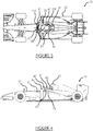
- FIG. 1 With reference to figures 2 to 4 , there is shown schematically an embodiment of a motor vehicle 10 according to the invention.
- a single-seater racing vehicle of the formula 1 type is shown.
- the invention applies to two-seater vehicles as well as to any vehicle whose cockpit is open, in particular of the Indycar type.
- the motor vehicle 10 comprises a chassis 20 extending longitudinally along an axis X, oriented from the rear to the front, to which the wheels 11 are fixed.
- the vehicle 10 also comprises a front nose 12 and a rear spoiler 13.
- the chassis 20 is the rigid structure on which the various elements of the vehicle 10 are mounted such as the transmission, motorization, etc. members. Such a chassis 20 is adapted to withstand significant mechanical stresses and also makes it possible to protect the pilot P as will be presented later. In the field of motor racing, such a chassis 20 is preferably a shell chassis. In other words, the chassis 20 is integrated into the body of the vehicle 10. Such a chassis 20 can, for example, be made of carbon fibers or aluminum in order to ensure good rigidity of the chassis 20 and to minimize its weight. In addition, the frame 20 can, for example, be tubular or molded.
- the chassis 20 further comprises an opening 21 allowing the driver P to access a cockpit 30.
- the cockpit 30 comprises a seat (not shown) on which the driver P is seated during an automobile race, and a steering wheel 31 for controlling the vehicle 10.
- the cockpit 30 is open, in other words, when the pilot P is installed in the cockpit 30, his head protrudes from said cockpit 30.
- the steering wheel 31 is removable to facilitate access by the pilot P to the cockpit 30.
- the seat can be removed from the cockpit 30 with the pilot P after an impact in order to maintain the back of the pilot P.
- the cockpit 30 is located in the chassis 20 in order to protect the pilot P as will be presented later.
- the opening 21 for access to the cockpit 30 extends longitudinally from front to rear and comprises a front part 21A, capable of receiving the steering wheel 31, and a part rear 21B able to receive the head of the pilot P.
- a head support is removably mounted to the lateral protection device 23.
- Such a head support has an overall U shape in order to hold the head of the pilot P in place inside cockpit 30 during a race.
- the chassis 20 comprises, on the one hand, a rear protection device 22 to protect the driver P in the event of the vehicle overturning 10 and facilitate its extraction and, on the other hand, two low side protection devices 23 of the driver P in order to protect, during an automobile race, the driver P in the event of a low side impact, that is to say, at the level of his cockpit 30, under the head of the pilot P.
- the rear protection device 22, known to a person skilled in the art under the name of "rear roll bar” or "central roll bar” or even “roll bar”, extends vertically upwards behind the piloting 30.
- the rear protection device 22 extends over a height of between 26 cm and 48 cm above the cockpit 30.
- the rear protection device 22 and the lateral protection devices low 23 are made of carbon fibers and is extra material from chassis 20.
- the vehicle 10 further comprises two protective members 40, positioned above the cockpit 30 and on each side of the opening 21.
- Such protective members 40 are configured to protect the head of the pilot P without disturbing his field of view.
- the driver's “field of vision” means the pilot's main field of vision, in other words when he looks towards the front of the vehicle.
- the protective members 40 do not disturb his field of vision by leaving him the view on the road.
- the two protective members 40 are positioned symmetrically on either side of the opening 21 and preferably have a symmetrically similar shape. Also, for the sake of clarity and conciseness, a single protective member 40 will now be described and all of the two protective members 40 will be described later.
- the protective member 40 is integrally mounted to said structural frame 20 according to a plurality of anchoring points.
- the protective member 40 is fixed to the chassis 20 at two anchor points P1, P2: a front anchor point P1 located laterally at the opening 21, preferably at a lateral protection device 23, more preferably at the front of the lateral protection device 23 and a rear anchoring point P2 located laterally at the opening 21, preferably at a lateral protection device 23, more preferably at the rear of the lateral protection device 23.
- the front anchoring point P1 is located laterally at the head of the pilot P in order to be out of his field of vision.
- the protective member 40 comprises a first portion 41, connecting the front anchoring point P1 to the rear anchoring point P2.
- the first portion 41 is bent.
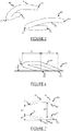
- the first portion 41 extends, up to a vertex S, in front of the front anchoring point P1, preferably at a longitudinal distance L1 greater than 18 cm, preferably of the order of 27 cm as illustrated in the figure 6 .
- the opening angle of the first portion 41 at the top S is between 25 ° and 35 °, preferably of the order of 29 °.
- the elbow of the first portion 41 is open, but it goes without saying that it could be full, in particular for aerodynamic or aesthetic imperatives.
- the first portion 41 extends vertically upwards from the front anchoring point P1 to the apex S over a height h1 of between 6 cm and 16 cm, preferably of the order of 9cm.
- the apex S although located in front of the front anchoring point P1, protects the head of the pilot P without interfering with his field of vision because the apex S extends in front and in height of the anchoring point before P1.
- the apex S extends above the pilot's field of vision P.
- the protection member 40 extends above the pilot's head P in order to protect him.
- the first portion 41 extends horizontally towards the rear of the vertex S, then extends obliquely downwards to the rear anchoring point P2. It goes without saying that the first portion 41 could extend obliquely down from the top S to the rear anchor point.
- the first portion 41 extends behind the front anchoring point P1, over a distance L2 of between 6 cm and 38 cm depending on the type of vehicle.
- the protection member 40 thus forms a high lateral protection for the pilot P.
- the first portion 41 comprises a first part, located between the front anchor point P1 and the apex S, and a second part, located between the apex S and the rear anchor point P2.
- the lateral distance e1 between the apex S and the front anchoring point is between 7 cm and 19 cm, preferably of the order of 11 cm so that the apex S is positioned towards the center of the vehicle 10 relative to the front anchoring point P1 so as to protect the pilot P as will be presented later while deviating to the side the objects coming from the front.
- the protective member 40 is in the form of a tubular structure.
- the first portion 41 of the protective member 40 has a substantially rectangular section.
- any other section for example circular, could be suitable.
- Such a tubular structure is discreet and does not visually impact the aesthetics of motor vehicles.
- the driver P remains visible from outside the vehicle 10 despite the presence of the support member 40.
- the tubular structure is full in order to optimize the mechanical resistance of the member protection 40.
- the tubular structure is hollow in order to limit the mass of the protection member 40 while having a high mechanical resistance.
- the protective member 40 is made from material of the chassis 20 in order to ensure the transmission of forces while making the manufacture of such a protective member 40 easy.
- a protection member 40 preferably made of carbon fiber, is light while having significant resistance to mechanical stresses.
- any mechanical force received by the protective member 40 is thus transmitted to the chassis 20, the mechanical forces then being optimally absorbed by the vehicle 10.
- a protective member 40 has been presented from the chassis material. 20, however it goes without saying that the protective member 40 could be removably attached to the chassis 20, for example to allow the position of the protective member 40 to be adjusted relative to the morphology of the pilot P.
- the two protective members 40 together have an overall U-shape above the opening 21 as illustrated in the figure 7 .
- Such a U-shape is open towards the front at the tops S of the protective members 40.
- Such an opening on the front makes it possible to leave the field of vision of the pilot P clear while allowing the extraction of the pilot P towards the 'front of the vehicle 10.
- a front opening distance e2 is defined, between 25 cm and 43 cm, preferably of the order of 29 cm, which corresponds to the lateral distance between the vertices S of the two protective members 40 , that is to say, the distance between the ends of the branches of the U as illustrated in the figure 7 .
- the opening distance before e2 is the shortest distance between the two protective members 40.
- Such a opening opening distance e2 is reduced thanks to the lateral bending towards the center of the vehicle 10 of the protective members 40
- Such an opening distance before e2 advantageously makes it possible to limit the area of passage of objects between the vertices S.
- the distance between the two protective members 40 is greater at the level of the pilot's head P in order to facilitate its extraction as will now be presented.
- All of the protective members 40 are open on the top in order to allow the extraction of the driver P from the top of the vehicle 10. Still with reference to the figure 7 , the U-shape of the two protective members 40 widens from front to back, preferably until a level distance e3 between the two protective members 40 of between 43 cm and 60 cm is obtained at the seat preferably of the order of 51 cm in order to allow, if necessary, the extraction of the pilot P from his seat so as to maintain his back following a significant shock.
- a U-shaped tightened on the front increases the front protection of the pilot P while facilitating the extraction of the pilot P.
- the motor vehicle 10 further comprises at least one protective bar 50 mounted between the two protective members 40 in order to reinforce the front protection of the driver P's head while maintaining the visibility of the driver P on the road, due to the placement of such a protective bar 50 in height.
- a protective bar 50 also makes it possible to distribute the mechanical forces between the two protective members in the event of an impact lateral at one of the protective members 40.
- the protective bar 50 is made of titanium in order to be resistant to significant mechanical stresses.
- the protective bar 50 may also have a section similar to that of the protective member 40 or less than the latter.
- the protection bar 50 is connected to each protection member 40 in the vicinity of its apex S so as not to be in the field of vision of the pilot P.
- the protection bar 50 is removably mounted so to facilitate the extraction of the pilot P by removing the protection bar.
- the protective bar 50 extends in an oblique plane relative to the horizontal plane, preferably oblique downwards. It goes without saying that the protective bar 50 could extend in a substantially horizontal plane.
- a motor vehicle 10 has been presented comprising two protective members 40, however, it goes without saying that the two protective members 40 could be connected at their rear anchor point P2 in order to form a single protective member having an overall U shape.
- a protective member 40 has been presented connected to the chassis 20 in only two anchor points P1, P2: the front anchor point P1 and the rear anchor point P2.
- the protective member 40 could be connected to the chassis 20 in addition to two anchoring points as will be presented later.
- the rear anchoring point P22 is located at the rear protective device 22.
- the first portion 41 extends, at least in part, vertically upwards between the vertex S and the point d rear anchor P2.
- the first portion 41 is thus at least partially increasing in height between the front anchor point P21 and the rear anchor point P22, preferably, strictly increasing.
- the first portion 41 extends vertically upwards from the front anchoring point P21 over a height of between 9 cm and 29 cm.
- the first portion 41 is, at least in part, inclined forward with respect to the horizontal plane in order to deflect an object coming from the front of the vehicle 10 upwards, this in order to limit the mechanical forces transmitted to the chassis 20 upon impact with the object.
- the protective member 40 is also fixed to the chassis 20 at least a third anchor point: an intermediate anchor point P23 located between the front anchor point P21 and the rear anchor point P22.
- the protective member 40 thus comprises a second portion 42 extending substantially vertically from the intermediate anchoring point P23 to the first portion 41.
- the second portion 42 is connected to the first portion 41 at a point of connection in order to strengthen the protective member 40 in the event of an impact.
- the connection point is located in a median zone of the first portion 41 in order to form an additional lateral protection in the event of an impact.
- the second portion 42 of the protective member 40 has a section similar to the section of the first portion 41 in order to facilitate the manufacture of the two portions 41, 42 of the protective member 40.
- An intermediate anchor point P23 has been presented separate from the front anchor point 41, however, it goes without saying that they could be confused, the second portion 42 thus connecting the front anchor point P21 to the first portion 41 at the level of its median zone.
- a protection member 40 has been presented, connected to the chassis 20 at three anchor points P21, P22, but it goes without saying that it could be connected at only two anchor points, as has been presented above. in order to limit the mass of the protective member 40.
- a second portion 42 extending vertically has been presented, however, it goes without saying that it could extend obliquely to the vertical plane.
- the opening angle of each protection member 40 at its top S is preferably less than 35 °.
- the protective member 40 has a pointed shape at its top S in order to facilitate the deflection of the objects upwards.
- the first portion 41 of the protection member is strictly increasing in height between the front anchoring point P31 and the rear anchoring point P32 in order to optimize the deflection of the objects upwards.
- the second portion 42 of the protection member extends forward from the intermediate anchoring point P33 located at a rear portion of the device.
- lateral protection 23 in order to increase the mechanical resistance of the protective member 40 in the event of a frontal impact.
- the intermediate anchoring point P33 could be located at a front part of the lateral protection device 23, the second portion 42 then being able to extend rearward.
- the protective member 40 is connected to the chassis 20 at three anchor points P31, P32, P33, but it goes without saying that it could be connected at only two anchor points like this. was previously presented in order to limit the mass of the protective member 40.
Landscapes
- Engineering & Computer Science (AREA)
- Mechanical Engineering (AREA)
- Body Structure For Vehicles (AREA)
Claims (10)
- Kraftfahrzeug (10), insbesondere für ein Autorennen, umfassend ein strukturelles Fahrgestell (20), das sich in Längsrichtung von hinten nach vorn erstreckt, und ein offenes Cockpit (30), der in dem strukturellen Fahrgestell (20) montiert ist, wobei das strukturelle Fahrgestell (20) eine Öffnung (21) umfasst, die einem Piloten (P) des genannten Fahrzeugs (10) das Zugreifen auf das genannte offene Cockpit (30) erlaubt, wobei die Öffnung (21) einen vorderen Teil (21A) umfasst, der zum Aufnehmen eines Steuerrades (31) geeignet ist, und eines hinteren Teils (21B), der zum Aufnehmen des Kopfes des genannten Piloten (P) geeignet ist, wobei das Fahrzeug (10) darüber hinaus wenigstens ein Schutzorgan (40) umfasst, das oberhalb des Cockpits (30) positioniert und gestaltet ist, um den Kopf des Piloten (P) zu schützen, wobei das Schutzorgan (40) gemäß einer Vielzahl von Verankerungspunkten fest mit dem genannten strukturellen Fahrgestell (20) montiert ist,- wobei der vorderste Verankerungspunkt (P1, P21, P31) lateral an der Öffnung (21) und an der Peripherie seines hinteren Teils (21B) angeordnet ist;- wobei das Schutzorgan (40) wenigstens einen Abschnitt (41) umfasst, der den vordersten Verankerungspunkt (P1, P21, P31) mit einem hinteren Verankerungspunkt (P2, P22, P32) verbindet, wobei sich der Abschnitt (41) vorne vom vordersten Verankerungspunkt (P1) erstreckt.
- Fahrzeug (1) gemäß Anspruch 1, wobei das Schutzorgan (40) sich vorne am vordersten Verankerungspunkt (P1, P21, P31) über eine Entfernung (L1) von mehr als 18 cm erstreckt.
- Fahrzeug (10) gemäß einem der voranstehenden Ansprüche, wobei das Schutzorgan (40) sich vorne am vordersten Verankerungspunkt (P1) bis zu einer Spitze (S) erstreckt, die Höhe (h1) zwischen dem vordersten Verankerungspunkt (P1, P21, P31) und der Spitze (S) ist zwischen 6 und 16 cm.
- Fahrzeug (10) gemäß einem der voranstehenden Ansprüche, wobei wenigstens ein vorderer Teil des Abschnitts (41) zur Öffnung (21) gekrümmt ist.
- Fahrzeug (10) gemäß einem der voranstehenden Ansprüche, umfassend wenigstens zwei Schutzorgane (40), die auf jeder Seite der Öffnung (21) positioniert sind.
- Fahrzeug (10) gemäß Anspruch 5, wobei die zwei Schutzorgane (40) eine allgemeine, an der Vorderseite offene U-Form aufweisen.
- Fahrzeug (10) gemäß dem voranstehenden Anspruch, wobei die Entfernung zwischen den Enden der Zweige des Us zwischen 25 cm und 43 cm inbegriffen ist.
- Fahrzeug gemäß einem der voranstehenden Ansprüche, wobei das Schutzorgan (40) aus Material des Fahrgestells (20) hervorgegangen ist, bevorzugt aus Kohlefasern hergestellt ist.
- Fahrzeug (10) gemäß einem der voranstehenden Ansprüche, wobei das Schutzorgan (40) einen ersten Abschnitt (41) umfasst, der den vordersten Verankerungspunkt (P1, P21, P31) mit einem hinteren Verankerungspunkt (P2, P22, P32) verbindet, das Schutzorgan (40) darüber hinaus einen zweiten Abschnitt (42) umfasst, der sich zwischen einem Zwischen-Verankerungspunkt (P23, P33) und dem ersten Abschnitt (41) des Schutzorgans (40) erstreckt.
- Fahrzeug (10) gemäß einem der Ansprüche 1 bis 9, wobei das Schutzorgan (40) eine röhrenförmige Struktur besitzt.
Applications Claiming Priority (3)
| Application Number | Priority Date | Filing Date | Title |
|---|---|---|---|
| FR1561260A FR3043962B1 (fr) | 2015-11-23 | 2015-11-23 | Vehicule automobile comprenant un organe de protection de la tete du pilote |
| US201562259466P | 2015-11-24 | 2015-11-24 | |
| PCT/EP2016/078347 WO2017089315A1 (fr) | 2015-11-23 | 2016-11-21 | Vehicule automobile comprenant un organe de protection de la tete du pilote |
Publications (2)
| Publication Number | Publication Date |
|---|---|
| EP3380367A1 EP3380367A1 (de) | 2018-10-03 |
| EP3380367B1 true EP3380367B1 (de) | 2020-01-01 |
Family
ID=55236658
Family Applications (1)
| Application Number | Title | Priority Date | Filing Date |
|---|---|---|---|
| EP16805027.6A Active EP3380367B1 (de) | 2015-11-23 | 2016-11-21 | Kraftfahrzeug mit einer schutzeinrichtung für den fahrerkopf |
Country Status (3)
| Country | Link |
|---|---|
| EP (1) | EP3380367B1 (de) |
| FR (1) | FR3043962B1 (de) |
| WO (1) | WO2017089315A1 (de) |
Families Citing this family (1)
| Publication number | Priority date | Publication date | Assignee | Title |
|---|---|---|---|---|
| FR3073799A1 (fr) * | 2017-11-17 | 2019-05-24 | Joel Haramboure | Systeme de protection pilote |
Family Cites Families (3)
| Publication number | Priority date | Publication date | Assignee | Title |
|---|---|---|---|---|
| DE29518030U1 (de) * | 1995-11-14 | 1996-03-28 | Schneider, René, 32791 Lage | Kopfschutzsystem für Formelfahrzeuge |
| US5947515A (en) * | 1997-08-25 | 1999-09-07 | Fitch; John C. | Driver safety capsule |
| NZ584740A (en) * | 2007-09-20 | 2013-01-25 | Richard Gale Scarf | Head restraint system for a person sitting in a seat in a vehicle activated by movement of a seatbelt |
-
2015
- 2015-11-23 FR FR1561260A patent/FR3043962B1/fr not_active Expired - Fee Related
-
2016
- 2016-11-21 WO PCT/EP2016/078347 patent/WO2017089315A1/fr not_active Ceased
- 2016-11-21 EP EP16805027.6A patent/EP3380367B1/de active Active
Non-Patent Citations (1)
| Title |
|---|
| None * |
Also Published As
| Publication number | Publication date |
|---|---|
| EP3380367A1 (de) | 2018-10-03 |
| WO2017089315A1 (fr) | 2017-06-01 |
| FR3043962B1 (fr) | 2018-01-05 |
| FR3043962A1 (fr) | 2017-05-26 |
Similar Documents
| Publication | Publication Date | Title |
|---|---|---|
| FR2896734A1 (fr) | Structure d'absorption de chocs pour siege de vehicule | |
| EP3380367B1 (de) | Kraftfahrzeug mit einer schutzeinrichtung für den fahrerkopf | |
| WO2023222962A1 (fr) | Véhicule automobile comprenant une pièce de protection du bloc de batterie. | |
| EP2969705B1 (de) | Kraftfahrzeug mit mittel zur positionierung einer zusammenschiebbaren lenksäule | |
| FR3106116A1 (fr) | Dispositif de masquage pour ensemble de direction | |
| EP2571744B1 (de) | Lenkanordnung für ein kraftfahrzeug | |
| FR3043963A1 (fr) | Vehicule automobile comprenant un organe de protection de la tete du pilote | |
| EP1805063B1 (de) | Mit schutzausrüstung bestücktes und mit seitlichem gleitelement versehenes go-kart sowie entsprechendes seitliches element und schutzausrüstung | |
| EP2443004B1 (de) | Vorrichtung für den schutz des fusses eines fahrzeuglenkers im falle eines frontalaufpralls | |
| FR3038574A1 (fr) | Structure de vehicule comportant un element de renfort et vehicule comportant une telle structure | |
| EP2008918B1 (de) | Kotflügel eines Fahrzeuges und Fahrzeug | |
| EP3154826B1 (de) | Anordnung eines armaturenbrettverkleidungsteils eines kraftfahrzeuges an einem tragenden element dieses armaturenbretts | |
| FR2582996A1 (fr) | Suspension a barre de torsion | |
| EP3303027B1 (de) | Plastisch verformbare schale zur montage eines rades eines kraftfahrzeuges | |
| FR2752213A1 (fr) | Perfectionnement pour chassis de vehicule | |
| EP3098149B1 (de) | Fahrradrahmen | |
| FR3106305A1 (fr) | Ensemble pare-soleil pour véhicule automobile | |
| FR3091840A1 (fr) | Ensemble d’affichage à parties combinables et élément de garnissage associé | |
| WO2016042065A1 (fr) | Motomarine comportant un flotteur avant muni d'un moyen de propulsion | |
| EP1190934B1 (de) | Lenkeinheit mit Lenkrad, Nabenkissen und Verkleidungsschale und damit ausgerüstetes Kraftfahrzeug | |
| FR3039109B1 (fr) | Vehicule comportant un element de blocage d’une roue directionnelle | |
| FR3166868A1 (fr) | Arrangement de châssis pour un véhicule triporteur | |
| FR3135950A1 (fr) | colonne de direction pour véhicule automobile | |
| FR3073799A1 (fr) | Systeme de protection pilote | |
| FR2923757A1 (fr) | Dispositif de reduction de tourbillons par deploiement d'element(s) longiline(s), pour un vehicule automobile decapotable. |
Legal Events
| Date | Code | Title | Description |
|---|---|---|---|
| STAA | Information on the status of an ep patent application or granted ep patent |
Free format text: STATUS: UNKNOWN |
|
| STAA | Information on the status of an ep patent application or granted ep patent |
Free format text: STATUS: THE INTERNATIONAL PUBLICATION HAS BEEN MADE |
|
| PUAI | Public reference made under article 153(3) epc to a published international application that has entered the european phase |
Free format text: ORIGINAL CODE: 0009012 |
|
| STAA | Information on the status of an ep patent application or granted ep patent |
Free format text: STATUS: REQUEST FOR EXAMINATION WAS MADE |
|
| 17P | Request for examination filed |
Effective date: 20180523 |
|
| AK | Designated contracting states |
Kind code of ref document: A1 Designated state(s): AL AT BE BG CH CY CZ DE DK EE ES FI FR GB GR HR HU IE IS IT LI LT LU LV MC MK MT NL NO PL PT RO RS SE SI SK SM TR |
|
| AX | Request for extension of the european patent |
Extension state: BA ME |
|
| DAV | Request for validation of the european patent (deleted) | ||
| DAX | Request for extension of the european patent (deleted) | ||
| GRAP | Despatch of communication of intention to grant a patent |
Free format text: ORIGINAL CODE: EPIDOSNIGR1 |
|
| STAA | Information on the status of an ep patent application or granted ep patent |
Free format text: STATUS: GRANT OF PATENT IS INTENDED |
|
| INTG | Intention to grant announced |
Effective date: 20190617 |
|
| GRAS | Grant fee paid |
Free format text: ORIGINAL CODE: EPIDOSNIGR3 |
|
| GRAA | (expected) grant |
Free format text: ORIGINAL CODE: 0009210 |
|
| STAA | Information on the status of an ep patent application or granted ep patent |
Free format text: STATUS: THE PATENT HAS BEEN GRANTED |
|
| AK | Designated contracting states |
Kind code of ref document: B1 Designated state(s): AL AT BE BG CH CY CZ DE DK EE ES FI FR GB GR HR HU IE IS IT LI LT LU LV MC MK MT NL NO PL PT RO RS SE SI SK SM TR |
|
| REG | Reference to a national code |
Ref country code: GB Ref legal event code: FG4D Free format text: NOT ENGLISH |
|
| REG | Reference to a national code |
Ref country code: CH Ref legal event code: EP Ref country code: AT Ref legal event code: REF Ref document number: 1219404 Country of ref document: AT Kind code of ref document: T Effective date: 20200115 |
|
| REG | Reference to a national code |
Ref country code: IE Ref legal event code: FG4D Free format text: LANGUAGE OF EP DOCUMENT: FRENCH |
|
| REG | Reference to a national code |
Ref country code: DE Ref legal event code: R096 Ref document number: 602016027481 Country of ref document: DE |
|
| REG | Reference to a national code |
Ref country code: NL Ref legal event code: MP Effective date: 20200101 |
|
| REG | Reference to a national code |
Ref country code: LT Ref legal event code: MG4D |
|
| PG25 | Lapsed in a contracting state [announced via postgrant information from national office to epo] |
Ref country code: CZ Free format text: LAPSE BECAUSE OF FAILURE TO SUBMIT A TRANSLATION OF THE DESCRIPTION OR TO PAY THE FEE WITHIN THE PRESCRIBED TIME-LIMIT Effective date: 20200101 Ref country code: NO Free format text: LAPSE BECAUSE OF FAILURE TO SUBMIT A TRANSLATION OF THE DESCRIPTION OR TO PAY THE FEE WITHIN THE PRESCRIBED TIME-LIMIT Effective date: 20200401 Ref country code: FI Free format text: LAPSE BECAUSE OF FAILURE TO SUBMIT A TRANSLATION OF THE DESCRIPTION OR TO PAY THE FEE WITHIN THE PRESCRIBED TIME-LIMIT Effective date: 20200101 Ref country code: RS Free format text: LAPSE BECAUSE OF FAILURE TO SUBMIT A TRANSLATION OF THE DESCRIPTION OR TO PAY THE FEE WITHIN THE PRESCRIBED TIME-LIMIT Effective date: 20200101 Ref country code: LT Free format text: LAPSE BECAUSE OF FAILURE TO SUBMIT A TRANSLATION OF THE DESCRIPTION OR TO PAY THE FEE WITHIN THE PRESCRIBED TIME-LIMIT Effective date: 20200101 Ref country code: PT Free format text: LAPSE BECAUSE OF FAILURE TO SUBMIT A TRANSLATION OF THE DESCRIPTION OR TO PAY THE FEE WITHIN THE PRESCRIBED TIME-LIMIT Effective date: 20200527 Ref country code: NL Free format text: LAPSE BECAUSE OF FAILURE TO SUBMIT A TRANSLATION OF THE DESCRIPTION OR TO PAY THE FEE WITHIN THE PRESCRIBED TIME-LIMIT Effective date: 20200101 |
|
| PG25 | Lapsed in a contracting state [announced via postgrant information from national office to epo] |
Ref country code: LV Free format text: LAPSE BECAUSE OF FAILURE TO SUBMIT A TRANSLATION OF THE DESCRIPTION OR TO PAY THE FEE WITHIN THE PRESCRIBED TIME-LIMIT Effective date: 20200101 Ref country code: SE Free format text: LAPSE BECAUSE OF FAILURE TO SUBMIT A TRANSLATION OF THE DESCRIPTION OR TO PAY THE FEE WITHIN THE PRESCRIBED TIME-LIMIT Effective date: 20200101 Ref country code: IS Free format text: LAPSE BECAUSE OF FAILURE TO SUBMIT A TRANSLATION OF THE DESCRIPTION OR TO PAY THE FEE WITHIN THE PRESCRIBED TIME-LIMIT Effective date: 20200501 Ref country code: GR Free format text: LAPSE BECAUSE OF FAILURE TO SUBMIT A TRANSLATION OF THE DESCRIPTION OR TO PAY THE FEE WITHIN THE PRESCRIBED TIME-LIMIT Effective date: 20200402 Ref country code: HR Free format text: LAPSE BECAUSE OF FAILURE TO SUBMIT A TRANSLATION OF THE DESCRIPTION OR TO PAY THE FEE WITHIN THE PRESCRIBED TIME-LIMIT Effective date: 20200101 Ref country code: BG Free format text: LAPSE BECAUSE OF FAILURE TO SUBMIT A TRANSLATION OF THE DESCRIPTION OR TO PAY THE FEE WITHIN THE PRESCRIBED TIME-LIMIT Effective date: 20200401 |
|
| REG | Reference to a national code |
Ref country code: DE Ref legal event code: R097 Ref document number: 602016027481 Country of ref document: DE |
|
| PG25 | Lapsed in a contracting state [announced via postgrant information from national office to epo] |
Ref country code: DK Free format text: LAPSE BECAUSE OF FAILURE TO SUBMIT A TRANSLATION OF THE DESCRIPTION OR TO PAY THE FEE WITHIN THE PRESCRIBED TIME-LIMIT Effective date: 20200101 Ref country code: EE Free format text: LAPSE BECAUSE OF FAILURE TO SUBMIT A TRANSLATION OF THE DESCRIPTION OR TO PAY THE FEE WITHIN THE PRESCRIBED TIME-LIMIT Effective date: 20200101 Ref country code: ES Free format text: LAPSE BECAUSE OF FAILURE TO SUBMIT A TRANSLATION OF THE DESCRIPTION OR TO PAY THE FEE WITHIN THE PRESCRIBED TIME-LIMIT Effective date: 20200101 Ref country code: RO Free format text: LAPSE BECAUSE OF FAILURE TO SUBMIT A TRANSLATION OF THE DESCRIPTION OR TO PAY THE FEE WITHIN THE PRESCRIBED TIME-LIMIT Effective date: 20200101 Ref country code: SK Free format text: LAPSE BECAUSE OF FAILURE TO SUBMIT A TRANSLATION OF THE DESCRIPTION OR TO PAY THE FEE WITHIN THE PRESCRIBED TIME-LIMIT Effective date: 20200101 Ref country code: SM Free format text: LAPSE BECAUSE OF FAILURE TO SUBMIT A TRANSLATION OF THE DESCRIPTION OR TO PAY THE FEE WITHIN THE PRESCRIBED TIME-LIMIT Effective date: 20200101 |
|
| PLBE | No opposition filed within time limit |
Free format text: ORIGINAL CODE: 0009261 |
|
| STAA | Information on the status of an ep patent application or granted ep patent |
Free format text: STATUS: NO OPPOSITION FILED WITHIN TIME LIMIT |
|
| REG | Reference to a national code |
Ref country code: AT Ref legal event code: MK05 Ref document number: 1219404 Country of ref document: AT Kind code of ref document: T Effective date: 20200101 |
|
| 26N | No opposition filed |
Effective date: 20201002 |
|
| PG25 | Lapsed in a contracting state [announced via postgrant information from national office to epo] |
Ref country code: AT Free format text: LAPSE BECAUSE OF FAILURE TO SUBMIT A TRANSLATION OF THE DESCRIPTION OR TO PAY THE FEE WITHIN THE PRESCRIBED TIME-LIMIT Effective date: 20200101 Ref country code: IT Free format text: LAPSE BECAUSE OF FAILURE TO SUBMIT A TRANSLATION OF THE DESCRIPTION OR TO PAY THE FEE WITHIN THE PRESCRIBED TIME-LIMIT Effective date: 20200101 |
|
| PGFP | Annual fee paid to national office [announced via postgrant information from national office to epo] |
Ref country code: GB Payment date: 20201223 Year of fee payment: 5 |
|
| PG25 | Lapsed in a contracting state [announced via postgrant information from national office to epo] |
Ref country code: SI Free format text: LAPSE BECAUSE OF FAILURE TO SUBMIT A TRANSLATION OF THE DESCRIPTION OR TO PAY THE FEE WITHIN THE PRESCRIBED TIME-LIMIT Effective date: 20200101 Ref country code: PL Free format text: LAPSE BECAUSE OF FAILURE TO SUBMIT A TRANSLATION OF THE DESCRIPTION OR TO PAY THE FEE WITHIN THE PRESCRIBED TIME-LIMIT Effective date: 20200101 |
|
| REG | Reference to a national code |
Ref country code: DE Ref legal event code: R119 Ref document number: 602016027481 Country of ref document: DE |
|
| PG25 | Lapsed in a contracting state [announced via postgrant information from national office to epo] |
Ref country code: MC Free format text: LAPSE BECAUSE OF FAILURE TO SUBMIT A TRANSLATION OF THE DESCRIPTION OR TO PAY THE FEE WITHIN THE PRESCRIBED TIME-LIMIT Effective date: 20200101 |
|
| REG | Reference to a national code |
Ref country code: CH Ref legal event code: PL |
|
| PG25 | Lapsed in a contracting state [announced via postgrant information from national office to epo] |
Ref country code: LU Free format text: LAPSE BECAUSE OF NON-PAYMENT OF DUE FEES Effective date: 20201121 |
|
| REG | Reference to a national code |
Ref country code: BE Ref legal event code: MM Effective date: 20201130 |
|
| PG25 | Lapsed in a contracting state [announced via postgrant information from national office to epo] |
Ref country code: CH Free format text: LAPSE BECAUSE OF NON-PAYMENT OF DUE FEES Effective date: 20201130 Ref country code: LI Free format text: LAPSE BECAUSE OF NON-PAYMENT OF DUE FEES Effective date: 20201130 |
|
| PG25 | Lapsed in a contracting state [announced via postgrant information from national office to epo] |
Ref country code: IE Free format text: LAPSE BECAUSE OF NON-PAYMENT OF DUE FEES Effective date: 20201121 |
|
| PG25 | Lapsed in a contracting state [announced via postgrant information from national office to epo] |
Ref country code: DE Free format text: LAPSE BECAUSE OF NON-PAYMENT OF DUE FEES Effective date: 20210601 |
|
| PG25 | Lapsed in a contracting state [announced via postgrant information from national office to epo] |
Ref country code: TR Free format text: LAPSE BECAUSE OF FAILURE TO SUBMIT A TRANSLATION OF THE DESCRIPTION OR TO PAY THE FEE WITHIN THE PRESCRIBED TIME-LIMIT Effective date: 20200101 Ref country code: MT Free format text: LAPSE BECAUSE OF FAILURE TO SUBMIT A TRANSLATION OF THE DESCRIPTION OR TO PAY THE FEE WITHIN THE PRESCRIBED TIME-LIMIT Effective date: 20200101 Ref country code: CY Free format text: LAPSE BECAUSE OF FAILURE TO SUBMIT A TRANSLATION OF THE DESCRIPTION OR TO PAY THE FEE WITHIN THE PRESCRIBED TIME-LIMIT Effective date: 20200101 |
|
| PG25 | Lapsed in a contracting state [announced via postgrant information from national office to epo] |
Ref country code: MK Free format text: LAPSE BECAUSE OF FAILURE TO SUBMIT A TRANSLATION OF THE DESCRIPTION OR TO PAY THE FEE WITHIN THE PRESCRIBED TIME-LIMIT Effective date: 20200101 Ref country code: AL Free format text: LAPSE BECAUSE OF FAILURE TO SUBMIT A TRANSLATION OF THE DESCRIPTION OR TO PAY THE FEE WITHIN THE PRESCRIBED TIME-LIMIT Effective date: 20200101 |
|
| GBPC | Gb: european patent ceased through non-payment of renewal fee |
Effective date: 20211121 |
|
| PG25 | Lapsed in a contracting state [announced via postgrant information from national office to epo] |
Ref country code: BE Free format text: LAPSE BECAUSE OF NON-PAYMENT OF DUE FEES Effective date: 20201130 |
|
| PG25 | Lapsed in a contracting state [announced via postgrant information from national office to epo] |
Ref country code: GB Free format text: LAPSE BECAUSE OF NON-PAYMENT OF DUE FEES Effective date: 20211121 |
|
| PGFP | Annual fee paid to national office [announced via postgrant information from national office to epo] |
Ref country code: FR Payment date: 20231127 Year of fee payment: 8 |
|
| PG25 | Lapsed in a contracting state [announced via postgrant information from national office to epo] |
Ref country code: FR Free format text: LAPSE BECAUSE OF NON-PAYMENT OF DUE FEES Effective date: 20241130 |