EP3380647B1 - Verfahren zur behandlung der oberfläche einer sich bewegenden folie und einrichtung zur implementierung dieses verfahrens - Google Patents
Verfahren zur behandlung der oberfläche einer sich bewegenden folie und einrichtung zur implementierung dieses verfahrens Download PDFInfo
- Publication number
- EP3380647B1 EP3380647B1 EP16721872.6A EP16721872A EP3380647B1 EP 3380647 B1 EP3380647 B1 EP 3380647B1 EP 16721872 A EP16721872 A EP 16721872A EP 3380647 B1 EP3380647 B1 EP 3380647B1
- Authority
- EP
- European Patent Office
- Prior art keywords
- head
- support
- substrate
- gas mixture
- enclosure
- Prior art date
- Legal status (The legal status is an assumption and is not a legal conclusion. Google has not performed a legal analysis and makes no representation as to the accuracy of the status listed.)
- Active
Links
Images




Classifications
-
- H—ELECTRICITY
- H01—ELECTRIC ELEMENTS
- H01J—ELECTRIC DISCHARGE TUBES OR DISCHARGE LAMPS
- H01J37/00—Discharge tubes with provision for introducing objects or material to be exposed to the discharge, e.g. for the purpose of examination or processing thereof
- H01J37/32—Gas-filled discharge tubes
- H01J37/32431—Constructional details of the reactor
- H01J37/32798—Further details of plasma apparatus not provided for in groups H01J37/3244 - H01J37/32788; special provisions for cleaning or maintenance of the apparatus
- H01J37/32816—Pressure
- H01J37/32825—Working under atmospheric pressure or higher
-
- C—CHEMISTRY; METALLURGY
- C23—COATING METALLIC MATERIAL; COATING MATERIAL WITH METALLIC MATERIAL; CHEMICAL SURFACE TREATMENT; DIFFUSION TREATMENT OF METALLIC MATERIAL; COATING BY VACUUM EVAPORATION, BY SPUTTERING, BY ION IMPLANTATION OR BY CHEMICAL VAPOUR DEPOSITION, IN GENERAL; INHIBITING CORROSION OF METALLIC MATERIAL OR INCRUSTATION IN GENERAL
- C23C—COATING METALLIC MATERIAL; COATING MATERIAL WITH METALLIC MATERIAL; SURFACE TREATMENT OF METALLIC MATERIAL BY DIFFUSION INTO THE SURFACE, BY CHEMICAL CONVERSION OR SUBSTITUTION; COATING BY VACUUM EVAPORATION, BY SPUTTERING, BY ION IMPLANTATION OR BY CHEMICAL VAPOUR DEPOSITION, IN GENERAL
- C23C16/00—Chemical coating by decomposition of gaseous compounds, without leaving reaction products of surface material in the coating, i.e. chemical vapour deposition [CVD] processes
- C23C16/44—Chemical coating by decomposition of gaseous compounds, without leaving reaction products of surface material in the coating, i.e. chemical vapour deposition [CVD] processes characterised by the method of coating
- C23C16/4401—Means for minimising impurities, e.g. dust, moisture or residual gas, in the reaction chamber
-
- C—CHEMISTRY; METALLURGY
- C23—COATING METALLIC MATERIAL; COATING MATERIAL WITH METALLIC MATERIAL; CHEMICAL SURFACE TREATMENT; DIFFUSION TREATMENT OF METALLIC MATERIAL; COATING BY VACUUM EVAPORATION, BY SPUTTERING, BY ION IMPLANTATION OR BY CHEMICAL VAPOUR DEPOSITION, IN GENERAL; INHIBITING CORROSION OF METALLIC MATERIAL OR INCRUSTATION IN GENERAL
- C23C—COATING METALLIC MATERIAL; COATING MATERIAL WITH METALLIC MATERIAL; SURFACE TREATMENT OF METALLIC MATERIAL BY DIFFUSION INTO THE SURFACE, BY CHEMICAL CONVERSION OR SUBSTITUTION; COATING BY VACUUM EVAPORATION, BY SPUTTERING, BY ION IMPLANTATION OR BY CHEMICAL VAPOUR DEPOSITION, IN GENERAL
- C23C16/00—Chemical coating by decomposition of gaseous compounds, without leaving reaction products of surface material in the coating, i.e. chemical vapour deposition [CVD] processes
- C23C16/44—Chemical coating by decomposition of gaseous compounds, without leaving reaction products of surface material in the coating, i.e. chemical vapour deposition [CVD] processes characterised by the method of coating
- C23C16/4412—Details relating to the exhausts, e.g. pumps, filters, scrubbers, particle traps
-
- C—CHEMISTRY; METALLURGY
- C23—COATING METALLIC MATERIAL; COATING MATERIAL WITH METALLIC MATERIAL; CHEMICAL SURFACE TREATMENT; DIFFUSION TREATMENT OF METALLIC MATERIAL; COATING BY VACUUM EVAPORATION, BY SPUTTERING, BY ION IMPLANTATION OR BY CHEMICAL VAPOUR DEPOSITION, IN GENERAL; INHIBITING CORROSION OF METALLIC MATERIAL OR INCRUSTATION IN GENERAL
- C23C—COATING METALLIC MATERIAL; COATING MATERIAL WITH METALLIC MATERIAL; SURFACE TREATMENT OF METALLIC MATERIAL BY DIFFUSION INTO THE SURFACE, BY CHEMICAL CONVERSION OR SUBSTITUTION; COATING BY VACUUM EVAPORATION, BY SPUTTERING, BY ION IMPLANTATION OR BY CHEMICAL VAPOUR DEPOSITION, IN GENERAL
- C23C16/00—Chemical coating by decomposition of gaseous compounds, without leaving reaction products of surface material in the coating, i.e. chemical vapour deposition [CVD] processes
- C23C16/44—Chemical coating by decomposition of gaseous compounds, without leaving reaction products of surface material in the coating, i.e. chemical vapour deposition [CVD] processes characterised by the method of coating
- C23C16/455—Chemical coating by decomposition of gaseous compounds, without leaving reaction products of surface material in the coating, i.e. chemical vapour deposition [CVD] processes characterised by the method of coating characterised by the method used for introducing gases into reaction chamber or for modifying gas flows in reaction chamber
- C23C16/45502—Flow conditions in reaction chamber
- C23C16/45504—Laminar flow
-
- C—CHEMISTRY; METALLURGY
- C23—COATING METALLIC MATERIAL; COATING MATERIAL WITH METALLIC MATERIAL; CHEMICAL SURFACE TREATMENT; DIFFUSION TREATMENT OF METALLIC MATERIAL; COATING BY VACUUM EVAPORATION, BY SPUTTERING, BY ION IMPLANTATION OR BY CHEMICAL VAPOUR DEPOSITION, IN GENERAL; INHIBITING CORROSION OF METALLIC MATERIAL OR INCRUSTATION IN GENERAL
- C23C—COATING METALLIC MATERIAL; COATING MATERIAL WITH METALLIC MATERIAL; SURFACE TREATMENT OF METALLIC MATERIAL BY DIFFUSION INTO THE SURFACE, BY CHEMICAL CONVERSION OR SUBSTITUTION; COATING BY VACUUM EVAPORATION, BY SPUTTERING, BY ION IMPLANTATION OR BY CHEMICAL VAPOUR DEPOSITION, IN GENERAL
- C23C16/00—Chemical coating by decomposition of gaseous compounds, without leaving reaction products of surface material in the coating, i.e. chemical vapour deposition [CVD] processes
- C23C16/44—Chemical coating by decomposition of gaseous compounds, without leaving reaction products of surface material in the coating, i.e. chemical vapour deposition [CVD] processes characterised by the method of coating
- C23C16/455—Chemical coating by decomposition of gaseous compounds, without leaving reaction products of surface material in the coating, i.e. chemical vapour deposition [CVD] processes characterised by the method of coating characterised by the method used for introducing gases into reaction chamber or for modifying gas flows in reaction chamber
- C23C16/45517—Confinement of gases to vicinity of substrate
-
- C—CHEMISTRY; METALLURGY
- C23—COATING METALLIC MATERIAL; COATING MATERIAL WITH METALLIC MATERIAL; CHEMICAL SURFACE TREATMENT; DIFFUSION TREATMENT OF METALLIC MATERIAL; COATING BY VACUUM EVAPORATION, BY SPUTTERING, BY ION IMPLANTATION OR BY CHEMICAL VAPOUR DEPOSITION, IN GENERAL; INHIBITING CORROSION OF METALLIC MATERIAL OR INCRUSTATION IN GENERAL
- C23C—COATING METALLIC MATERIAL; COATING MATERIAL WITH METALLIC MATERIAL; SURFACE TREATMENT OF METALLIC MATERIAL BY DIFFUSION INTO THE SURFACE, BY CHEMICAL CONVERSION OR SUBSTITUTION; COATING BY VACUUM EVAPORATION, BY SPUTTERING, BY ION IMPLANTATION OR BY CHEMICAL VAPOUR DEPOSITION, IN GENERAL
- C23C16/00—Chemical coating by decomposition of gaseous compounds, without leaving reaction products of surface material in the coating, i.e. chemical vapour deposition [CVD] processes
- C23C16/44—Chemical coating by decomposition of gaseous compounds, without leaving reaction products of surface material in the coating, i.e. chemical vapour deposition [CVD] processes characterised by the method of coating
- C23C16/455—Chemical coating by decomposition of gaseous compounds, without leaving reaction products of surface material in the coating, i.e. chemical vapour deposition [CVD] processes characterised by the method of coating characterised by the method used for introducing gases into reaction chamber or for modifying gas flows in reaction chamber
- C23C16/45563—Gas nozzles
- C23C16/45574—Nozzles for more than one gas
-
- C—CHEMISTRY; METALLURGY
- C23—COATING METALLIC MATERIAL; COATING MATERIAL WITH METALLIC MATERIAL; CHEMICAL SURFACE TREATMENT; DIFFUSION TREATMENT OF METALLIC MATERIAL; COATING BY VACUUM EVAPORATION, BY SPUTTERING, BY ION IMPLANTATION OR BY CHEMICAL VAPOUR DEPOSITION, IN GENERAL; INHIBITING CORROSION OF METALLIC MATERIAL OR INCRUSTATION IN GENERAL
- C23C—COATING METALLIC MATERIAL; COATING MATERIAL WITH METALLIC MATERIAL; SURFACE TREATMENT OF METALLIC MATERIAL BY DIFFUSION INTO THE SURFACE, BY CHEMICAL CONVERSION OR SUBSTITUTION; COATING BY VACUUM EVAPORATION, BY SPUTTERING, BY ION IMPLANTATION OR BY CHEMICAL VAPOUR DEPOSITION, IN GENERAL
- C23C16/00—Chemical coating by decomposition of gaseous compounds, without leaving reaction products of surface material in the coating, i.e. chemical vapour deposition [CVD] processes
- C23C16/44—Chemical coating by decomposition of gaseous compounds, without leaving reaction products of surface material in the coating, i.e. chemical vapour deposition [CVD] processes characterised by the method of coating
- C23C16/455—Chemical coating by decomposition of gaseous compounds, without leaving reaction products of surface material in the coating, i.e. chemical vapour deposition [CVD] processes characterised by the method of coating characterised by the method used for introducing gases into reaction chamber or for modifying gas flows in reaction chamber
- C23C16/45563—Gas nozzles
- C23C16/45578—Elongated nozzles, tubes with holes
-
- C—CHEMISTRY; METALLURGY
- C23—COATING METALLIC MATERIAL; COATING MATERIAL WITH METALLIC MATERIAL; CHEMICAL SURFACE TREATMENT; DIFFUSION TREATMENT OF METALLIC MATERIAL; COATING BY VACUUM EVAPORATION, BY SPUTTERING, BY ION IMPLANTATION OR BY CHEMICAL VAPOUR DEPOSITION, IN GENERAL; INHIBITING CORROSION OF METALLIC MATERIAL OR INCRUSTATION IN GENERAL
- C23C—COATING METALLIC MATERIAL; COATING MATERIAL WITH METALLIC MATERIAL; SURFACE TREATMENT OF METALLIC MATERIAL BY DIFFUSION INTO THE SURFACE, BY CHEMICAL CONVERSION OR SUBSTITUTION; COATING BY VACUUM EVAPORATION, BY SPUTTERING, BY ION IMPLANTATION OR BY CHEMICAL VAPOUR DEPOSITION, IN GENERAL
- C23C16/00—Chemical coating by decomposition of gaseous compounds, without leaving reaction products of surface material in the coating, i.e. chemical vapour deposition [CVD] processes
- C23C16/44—Chemical coating by decomposition of gaseous compounds, without leaving reaction products of surface material in the coating, i.e. chemical vapour deposition [CVD] processes characterised by the method of coating
- C23C16/455—Chemical coating by decomposition of gaseous compounds, without leaving reaction products of surface material in the coating, i.e. chemical vapour deposition [CVD] processes characterised by the method of coating characterised by the method used for introducing gases into reaction chamber or for modifying gas flows in reaction chamber
- C23C16/45587—Mechanical means for changing the gas flow
- C23C16/45591—Fixed means, e.g. wings, baffles
-
- C—CHEMISTRY; METALLURGY
- C23—COATING METALLIC MATERIAL; COATING MATERIAL WITH METALLIC MATERIAL; CHEMICAL SURFACE TREATMENT; DIFFUSION TREATMENT OF METALLIC MATERIAL; COATING BY VACUUM EVAPORATION, BY SPUTTERING, BY ION IMPLANTATION OR BY CHEMICAL VAPOUR DEPOSITION, IN GENERAL; INHIBITING CORROSION OF METALLIC MATERIAL OR INCRUSTATION IN GENERAL
- C23C—COATING METALLIC MATERIAL; COATING MATERIAL WITH METALLIC MATERIAL; SURFACE TREATMENT OF METALLIC MATERIAL BY DIFFUSION INTO THE SURFACE, BY CHEMICAL CONVERSION OR SUBSTITUTION; COATING BY VACUUM EVAPORATION, BY SPUTTERING, BY ION IMPLANTATION OR BY CHEMICAL VAPOUR DEPOSITION, IN GENERAL
- C23C16/00—Chemical coating by decomposition of gaseous compounds, without leaving reaction products of surface material in the coating, i.e. chemical vapour deposition [CVD] processes
- C23C16/44—Chemical coating by decomposition of gaseous compounds, without leaving reaction products of surface material in the coating, i.e. chemical vapour deposition [CVD] processes characterised by the method of coating
- C23C16/455—Chemical coating by decomposition of gaseous compounds, without leaving reaction products of surface material in the coating, i.e. chemical vapour deposition [CVD] processes characterised by the method of coating characterised by the method used for introducing gases into reaction chamber or for modifying gas flows in reaction chamber
- C23C16/45595—Atmospheric CVD gas inlets with no enclosed reaction chamber
-
- C—CHEMISTRY; METALLURGY
- C23—COATING METALLIC MATERIAL; COATING MATERIAL WITH METALLIC MATERIAL; CHEMICAL SURFACE TREATMENT; DIFFUSION TREATMENT OF METALLIC MATERIAL; COATING BY VACUUM EVAPORATION, BY SPUTTERING, BY ION IMPLANTATION OR BY CHEMICAL VAPOUR DEPOSITION, IN GENERAL; INHIBITING CORROSION OF METALLIC MATERIAL OR INCRUSTATION IN GENERAL
- C23C—COATING METALLIC MATERIAL; COATING MATERIAL WITH METALLIC MATERIAL; SURFACE TREATMENT OF METALLIC MATERIAL BY DIFFUSION INTO THE SURFACE, BY CHEMICAL CONVERSION OR SUBSTITUTION; COATING BY VACUUM EVAPORATION, BY SPUTTERING, BY ION IMPLANTATION OR BY CHEMICAL VAPOUR DEPOSITION, IN GENERAL
- C23C16/00—Chemical coating by decomposition of gaseous compounds, without leaving reaction products of surface material in the coating, i.e. chemical vapour deposition [CVD] processes
- C23C16/44—Chemical coating by decomposition of gaseous compounds, without leaving reaction products of surface material in the coating, i.e. chemical vapour deposition [CVD] processes characterised by the method of coating
- C23C16/50—Chemical coating by decomposition of gaseous compounds, without leaving reaction products of surface material in the coating, i.e. chemical vapour deposition [CVD] processes characterised by the method of coating using electric discharges
-
- C—CHEMISTRY; METALLURGY
- C23—COATING METALLIC MATERIAL; COATING MATERIAL WITH METALLIC MATERIAL; CHEMICAL SURFACE TREATMENT; DIFFUSION TREATMENT OF METALLIC MATERIAL; COATING BY VACUUM EVAPORATION, BY SPUTTERING, BY ION IMPLANTATION OR BY CHEMICAL VAPOUR DEPOSITION, IN GENERAL; INHIBITING CORROSION OF METALLIC MATERIAL OR INCRUSTATION IN GENERAL
- C23C—COATING METALLIC MATERIAL; COATING MATERIAL WITH METALLIC MATERIAL; SURFACE TREATMENT OF METALLIC MATERIAL BY DIFFUSION INTO THE SURFACE, BY CHEMICAL CONVERSION OR SUBSTITUTION; COATING BY VACUUM EVAPORATION, BY SPUTTERING, BY ION IMPLANTATION OR BY CHEMICAL VAPOUR DEPOSITION, IN GENERAL
- C23C16/00—Chemical coating by decomposition of gaseous compounds, without leaving reaction products of surface material in the coating, i.e. chemical vapour deposition [CVD] processes
- C23C16/44—Chemical coating by decomposition of gaseous compounds, without leaving reaction products of surface material in the coating, i.e. chemical vapour deposition [CVD] processes characterised by the method of coating
- C23C16/52—Controlling or regulating the coating process
-
- C—CHEMISTRY; METALLURGY
- C23—COATING METALLIC MATERIAL; COATING MATERIAL WITH METALLIC MATERIAL; CHEMICAL SURFACE TREATMENT; DIFFUSION TREATMENT OF METALLIC MATERIAL; COATING BY VACUUM EVAPORATION, BY SPUTTERING, BY ION IMPLANTATION OR BY CHEMICAL VAPOUR DEPOSITION, IN GENERAL; INHIBITING CORROSION OF METALLIC MATERIAL OR INCRUSTATION IN GENERAL
- C23C—COATING METALLIC MATERIAL; COATING MATERIAL WITH METALLIC MATERIAL; SURFACE TREATMENT OF METALLIC MATERIAL BY DIFFUSION INTO THE SURFACE, BY CHEMICAL CONVERSION OR SUBSTITUTION; COATING BY VACUUM EVAPORATION, BY SPUTTERING, BY ION IMPLANTATION OR BY CHEMICAL VAPOUR DEPOSITION, IN GENERAL
- C23C16/00—Chemical coating by decomposition of gaseous compounds, without leaving reaction products of surface material in the coating, i.e. chemical vapour deposition [CVD] processes
- C23C16/44—Chemical coating by decomposition of gaseous compounds, without leaving reaction products of surface material in the coating, i.e. chemical vapour deposition [CVD] processes characterised by the method of coating
- C23C16/54—Apparatus specially adapted for continuous coating
- C23C16/545—Apparatus specially adapted for continuous coating for coating elongated substrates
-
- H—ELECTRICITY
- H01—ELECTRIC ELEMENTS
- H01J—ELECTRIC DISCHARGE TUBES OR DISCHARGE LAMPS
- H01J37/00—Discharge tubes with provision for introducing objects or material to be exposed to the discharge, e.g. for the purpose of examination or processing thereof
- H01J37/32—Gas-filled discharge tubes
- H01J37/32009—Arrangements for generation of plasma specially adapted for examination or treatment of objects, e.g. plasma sources
- H01J37/32366—Localised processing
-
- H—ELECTRICITY
- H01—ELECTRIC ELEMENTS
- H01J—ELECTRIC DISCHARGE TUBES OR DISCHARGE LAMPS
- H01J37/00—Discharge tubes with provision for introducing objects or material to be exposed to the discharge, e.g. for the purpose of examination or processing thereof
- H01J37/32—Gas-filled discharge tubes
- H01J37/32431—Constructional details of the reactor
- H01J37/3244—Gas supply means
- H01J37/32449—Gas control, e.g. control of the gas flow
-
- H—ELECTRICITY
- H01—ELECTRIC ELEMENTS
- H01J—ELECTRIC DISCHARGE TUBES OR DISCHARGE LAMPS
- H01J37/00—Discharge tubes with provision for introducing objects or material to be exposed to the discharge, e.g. for the purpose of examination or processing thereof
- H01J37/32—Gas-filled discharge tubes
- H01J37/32431—Constructional details of the reactor
- H01J37/32532—Electrodes
- H01J37/32568—Relative arrangement or disposition of electrodes; moving means
-
- H—ELECTRICITY
- H01—ELECTRIC ELEMENTS
- H01J—ELECTRIC DISCHARGE TUBES OR DISCHARGE LAMPS
- H01J37/00—Discharge tubes with provision for introducing objects or material to be exposed to the discharge, e.g. for the purpose of examination or processing thereof
- H01J37/32—Gas-filled discharge tubes
- H01J37/32431—Constructional details of the reactor
- H01J37/32733—Means for moving the material to be treated
-
- H—ELECTRICITY
- H01—ELECTRIC ELEMENTS
- H01J—ELECTRIC DISCHARGE TUBES OR DISCHARGE LAMPS
- H01J37/00—Discharge tubes with provision for introducing objects or material to be exposed to the discharge, e.g. for the purpose of examination or processing thereof
- H01J37/32—Gas-filled discharge tubes
- H01J37/32431—Constructional details of the reactor
- H01J37/32733—Means for moving the material to be treated
- H01J37/32752—Means for moving the material to be treated for moving the material across the discharge
- H01J37/32761—Continuous moving
- H01J37/3277—Continuous moving of continuous material
Definitions
- the invention relates to a method for surface treatment of a moving substrate. It relates more specifically to a process in which the substrate is subjected to a plasma generated in a gaseous mixture, which leads to the modification of the surface state of this substrate and / or to the formation of a deposit on the aforementioned surface .
- the invention relates in particular to such a process, which can be carried out at a pressure close to atmospheric pressure, and which is suitable for the continuous surface treatment of polymer films in coils ("roll-to-roll" process ").
- Such properties of interest may be, for example, the surface energy or the adhesion properties of this substrate.
- the substrates targeted by the invention may be in particular insulators such as polymer films, or even metal films.
- this surface is subjected to a plasma created by an electric discharge in a gas and, simultaneously or subsequently, the substrate thus treated is exposed to a gaseous mixture which contains an active gaseous compound capable of inducing the deposition of this thin solid film.
- the latter contains, in addition to the electrodes necessary for the creation of the discharge, a device for injecting the active gas mixture, as well as means for evacuation of gaseous effluents.
- US-B-8,851,012 discloses a method of treating the surface of a substrate, using a head equipped with a first electrode, and a central channel for supplying a polymer or a carrier gas via auxiliary channels.
- This document teaches certain dimensional ranges, particularly as regards the distance between the substrate and the injection members of the various gaseous compounds.
- This document provides a spatial separation between the injection of a carrier gas and the diffusion of a plasma gas.
- EP-A-2 762 609 relates to a method of surface treatment of a moving substrate, into which an inert gas and an active gas mixture are introduced into a support, then the reactive gas is activated and the surface of the aforementioned substrate is treated. The gaseous atmosphere is then evacuated, which comprises a fraction of the inert gas and the active gas mixture.
- US 2003/113479 discloses a plasma processing apparatus, comprising two opposing electrodes defining a discharge space, and means for supplying a reactive gas and an inert gas to said discharge space.
- the reactive gas is excited in this discharge space by applying a voltage, but is not brought into direct contact with the discharge surface of the two aforementioned electrodes.
- FR 2 816 726 A describes a method of the above type, which is implemented by means of an installation comprising a chamber for receiving the electrodes.
- This installation is further provided with auxiliary units, to respectively prevent the entry of air into the chamber, and the output of the gas mixture out of this chamber.
- Each auxiliary unit comprises a nitrogen injection slot for the creation, in use, of "knives” gaseous.
- Means are further provided for regulating the gas flow rates, so as to maintain a pressure difference close to zero between the interior of the chamber and the outside atmosphere.
- FR-A-2,816,726 involves some disadvantages. Firstly, it uses gaseous knives that involve a high consumption of nitrogen. In addition, the control of the conditions inside the chamber is relatively complex to implement. In particular, the pressure inside the chamber is difficult to regulate stably and reproducibly. In other words, this pressure is subject to significant variations, which are not favorable to the proper control of this process. Finally the installation described in FR-A-2,816,726 , allowing the implementation of this method, is relatively heavy and expensive.
- an object of the present invention is to overcome, at least partially, the disadvantages of the prior art mentioned above.
- Another objective of the invention is to propose a method which, while ensuring a reliable surface treatment of a substrate, in particular of the "roll to roll” type, at a pressure close to atmospheric pressure, makes it possible to significantly reduce the amount of inert gas consumed, compared to the prior art.
- Another object of the invention is to provide such a method, which is convenient to drive and which can be implemented using a relatively simple installation.
- the method according to the invention makes it possible to dispense with the use of input and output units associated with nitrogen knives, as known from FR-A-2,816,726 . Therefore, this process allows a substantial reduction in the consumption of inert gas, compared to this state of the art.
- the overall structure of the installation, allowing the implementation of the method of the invention, is significantly simplified.
- the Applicant has discovered that, surprisingly, the fact of injecting the active gas mixture in the vicinity of the substrate, while diffusing the inert gas from inside the chamber itself, provides a plasma treatment of satisfactory quality. Indeed, this avoids any substantial leakage of this active gas mixture out of the chamber. In other words, substantially all of the reactive gas is deposited on the plasma-exposed surfaces.
- the inventors believe that this may be due to the fact that the gaseous mixture is repelled, or plated, against the substrate, under the effect of the inert gas.
- the latter also avoids any significant entry into the discharge zone defined by the electrodes, air optionally loaded with impurities such as dust, carried by the moving substrate.
- This plating effect of the gaseous mixture, by the inert gas, is also ensured by the slight overpressure of the head relative to the rest of the enclosure.
- the pressure difference between the interior volumes of this head and this chamber is typically greater than 10 Pascal (Pa).
- this difference is greater than 20 Pascal, in particular 50 Pascal.
- the present invention is advantageous in terms of security and flexibility, compared to the solution described in FR-A-2,816,726 .
- the treatment chamber can not be placed at a high pressure value, in order to avoid significant leakage of nitrogen into the ambient atmosphere.
- this excess pressure is low, or that there is a reversal of pressures likely to induce an inadvertent arrival of oxygen in the chamber.
- the value of the overpressure used in the present invention can first be modified by adjusting the effective section of the outlet. This is typically achieved by acting on the position of the head relative to the support. In this case, if the head is moved away from the support, this tends to reduce the value of this overpressure whereas, if the head is brought closer, the value of this overpressure is increased.
- the installation furthermore comprises an auxiliary chamber, placed upstream of the enclosure, said auxiliary chamber being provided with at least one pressing roll adapted to at least partially eliminate the layer of air present at the surface of the substrate.
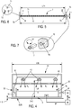
- the installation of the invention firstly comprises a body or enclosure 10, which has an upper wall 11 and peripheral walls, formed by parallel front walls 12 and rear 13, as well as parallel side walls 14 and 15.
- a body or enclosure 10 which has an upper wall 11 and peripheral walls, formed by parallel front walls 12 and rear 13, as well as parallel side walls 14 and 15.
- its length L10 namely the distance between the walls 12 and 13 is between 1000 mm and 2000 mm.
- its width l10 namely the distance between the walls 14 and 15, is between 1000 mm and 2000 mm.
- the enclosure is also provided with a pipe 17, of a type known per se, in order to suck up an excess of gas out of the interior volume of the enclosure 10.
- rails 16 extend between the walls 12 and 13. They are fixed on these walls, by any appropriate means. The function of these rails will be described in the following.
- a window 18 and a door 19 are provided on the rear wall 13, to allow access to the rails 16.
- the installation further comprises a drum 20 which is rotated, in use, in the direction shown by the arrow R20.
- This drum forms a support for the substrate SUB intended to be treated in accordance with the invention.
- this drum provides an additional counter-electrode function, which cooperates with electrodes which will be described in what follows.
- this counter electrode can be formed by another component of the installation.
- the substrate is made of polypropylene, while its thickness is between 20 and 100 microns.
- the drum In its upstream part, with reference to the displacement of the substrate, the drum is associated with a pressure roller 22 (called by the skilled person also "nip"), of a type known per se.
- This secondary roller 22 makes it possible to press the substrate against the drum 20, so as to avoid the formation of a layer of air between this substrate and this drum. This makes it possible to avoid any local defect of treatment on the substrate.
- a head 30 is provided, which is equipped with tubes and electrodes, as will be explained in the following.
- the width 130 of the head 30 is significantly smaller than that l10 of the enclosure. This head extends along an arc of the circle defined by the drum 20, approximately centrally.
- the length L30 of this head is for example slightly less than that L10, particularly if the substrate covers substantially the entire length of the drum. However, if this substrate covers only a portion of this drum, the length L30 of this head can be significantly smaller than L10, so that the head does not protrude longitudinally beyond the substrate.
- the head 30 comprises a cover 31 and peripheral walls, formed by parallel walls front and rear 32 and 33, as well as by side walls 34 and 35.
- the head 30 is made of PET (polyethylene terephthalate) .
- PET polyethylene terephthalate
- the front wall 32 is omitted on the figure 3 , while she is represented on the figure 4 .
- this attachment makes it possible to mount the head 30 on the rails 16 in a removable manner, in particular by snapping.
- This head 30 defines an internal volume V which is open towards the drum 20.
- the latter defines, with each free edge 30E and 30S of the head, two spaces E and S respectively forming an input E and an output S.
- the input E corresponds to the upstream side, through which the substrate is admitted, while the output S corresponds to the downstream side. As will be described in more detail in the following, this output ensures the continuous evacuation of the gaseous atmosphere initially present in the volume V.
- each space E and S namely the distance between each free edge 30E, 30S and the support, is typically between 0.5 and 2.5 millimeters, preferably between 0.8 and 1.2 millimeters. If this height is too low, the output of inert gas is insufficient and the lamination effect is not satisfactory. On the other hand, if this height is too high, there is not a sufficient pressure value between the head and the rest of the enclosure.
- the HS height is represented, the output cross-section S being defined by the product (HS * L30) of the height HS by the length L30.
- each space E and S can be modified, by moving the head 30 relative to the drum 20. This possibility is shown by the arrow T30 which underlines the translational movement of the head relative to the support, as well as by the arrow R30 which highlights the rotational movement of this head relative to this support. As will be explained in the following, the modification of the relative position of the head and the support makes it possible to modify the effective section of the output.
- the head is divided into two parts by a filter 60, hereinafter referred to as upper 40 and lower 50.
- a filter 60 hereinafter referred to as upper 40 and lower 50.
- the head is provided with diffusion means connected to a source of inert gas such as nitrogen as will be described in the following.
- these diffusion means are formed of several diffusers 42, of any appropriate type.
- D42 the injection distance, namely the distance between the outlet of the diffusers 42 and SUB substrate.
- These diffusers which have a plurality of diffusion holes, are formed regularly on the surface of the head.
- This filter which is known per se, has among others the function of improving the homogeneity of the nitrogen sent to the lower part 50 of the head.
- the lower part 50 of the head firstly receives injection members of an active gas mixture.
- these members are injection tubes 7, 7 'and 7 ", three in number, or alternatively, a different number of injection members may be provided and / or provide that these injection members are structurally different from a tube, namely that they are formed for example by a perforated bar.
- the lower portion 50 of the head further receives three electrodes 8, 8 'and 8 ", which are arranged alternately with respect to the tubes 7, 7' and 7", in the direction of rotation of the drum.
- the upstream tube 7 is placed between the side wall 34 and the upstream electrode 8, while the tubes 7 'and 7 "are placed between adjacent electrodes, namely 8, 8' and 8 ', 8 ".
- the invention encompasses other mutual arrangements of tubes and electrodes.
- two electrodes may be placed side by side, or a first tube may be disposed between an upstream electrode 8 "and the side wall 35.
- Two tubes may also be placed side by side, being arranged between two electrodes or between a side wall and an electrode.
- the tubes are made of metal, or of plastics material, such as a polymer material, in particular PET. They are connected to a not shown source of an active gas mixture, in order to perform a plasma treatment of the substrate SUB.
- the tube 7 is elongated and has a circular cross section. Its length L7, which is slightly less than that L30 of the head, is included as an example between 20 and 2000 millimeters. Its outer diameter D7 is for example between 10 and 20 millimeters.
- the tube 7 is pierced by two parallel rows 71 and 72 of injection orifices, made by any appropriate method. These orifices extend along a length L71, which represents a substantial part of the total length of these tubes.
- each tube is mounted on flanges 76, located close to the front and rear walls, respectively.
- at least one of these ends is fixed on a yoke 78, supported by a respective flange, which is in the form of a cylinder part (see FIG. figure 7 ).
- this tube can be rotated about its main longitudinal axis, as shown by the arrow R7, which makes it possible to vary the injection angle of the gaseous mixture towards the substrate. This ensures a reduction of the effects due to the injection turbulence, as will be explained in the following.
- each electrode has a smooth outer surface, which avoids the creation of turbulence in the plasma formation zone.
- This electrode is preferably made of ceramic material, which makes it possible to treat an electrically conductive substrate.
- the electrodes may be made of any other suitable material, such as metallic material.
- the electrode 8 is elongated and has a square cross-section. Its length L8 is substantially equal to that L7 of the tube 7, while its width 18 is similar to the diameter D7 of the tube 7, in particular between 10 and 20 millimeters.
- each electrode Both ends of each electrode are attached to the flanges 76 ( figure 4 ), near the ends of the tubes. Unlike tubes, these electrodes are not mounted on these flanges with a possibility of rotation.
- the electrodes 8 are connected to a source of very high voltage, not shown.
- the electrodes 8 are connected to a common source of nitrogen 90, via upstream lines 91.
- the nitrogen flows along these electrodes, then downstream lines 92 which open into each diffuser 42.
- a sensor 94 of any suitable type, is adapted to measure the oxygen content in the vicinity of the electrodes. As shown in figure 3 , the sensor is positioned near the entrance E. This sensor is connected to a control device 96, via a line 97, so as to control the flow of nitrogen through an additional line 98, which opens into the source 90.
- the smallest distance between the injection ports 71, 72 and the substrate SUB is referenced d7, while d8 is the smallest distance between each electrode 8 and the substrate.
- the distance d8 is for example between 500 and 2500 micrometers, typically between 500 and 1500 micrometers, in particular equal to 1000 micrometers.
- the distance d7 is slightly greater than that d8. In this way the head can be positioned relative to the counter electrode 20, as explained above, without risk of contact between the tubes 7 and against this electrode.
- Each tube is disposed substantially equidistant from the two electrodes, between which it is located.
- the smallest distance d78 between a tube and an electrode is between 5 and 10 millimeters. If the distance d78 is too low, an electric arc may occur. On the other hand, if d78 is too high, this can create a substantial dead volume, in which gaseous mixture can flow.
- nitrogen is first admitted into the volume V via the diffusers 42.
- the substrate is not set in motion until the oxygen concentration measured by the sensor 94 falls below below a given threshold, for example equal to 20 ppm (parts per million).
- a given threshold for example equal to 20 ppm (parts per million).
- the reactive gas may therefore consist of the monomer or the dopant or a mixture of monomer and dopant.
- the ratio between the volume fractions of the dopant and the monomer is, for example, between 10 and 30.
- the gaseous mixture may consist of the reactive gas, that is, it does not include a substantial fraction of another component.
- the gaseous mixture may consist of one or more dopants alone, especially in the case where the latter are suitable for such a particular safe use, such as N 2 O or CO 2 .
- the gaseous mixture may comprise, in addition to the reactive gas, a carrier gas.
- a carrier gas can be defined as a gas capable of transporting the reactive gas, without modifying the nature of the latter or the nature of the substrate.
- the ratio between the volume fractions of the carrier gas and the reactive gas is, for example, between 10 and 100.
- a carrier gas which is identical to the inert gas injected by the diffusers 42.
- it may be typically nitrogen.
- a carrier gas which is different from the inert gas it is possible to choose a carrier gas which has improved plasmagenic properties with respect to nitrogen, such as a noble gas such as helium. Indeed, since the amount of carrier gas used is much less than the amount of inert gas, this does not generate unacceptable additional costs.
- One of the applications targeted by the invention is plasma assisted deposition.
- a reactive mixture composed of at least one monomer, advantageously associated with at least one dopant and with a carrier gas, is used. Since the dopant is injected at the same time as the monomer, this increases the quality and the homogeneity of the deposit, in particular thanks to the fact that the ratio between their concentrations is homogeneous over the treated surface of the substrate.
- Another of the applications targeted by the invention is plasma-assisted grafting.
- a reactive mixture composed of at least one dopant, associated optionally with a carrier gas, is used. Since the dopant is injected as close to the substrate, it has a very satisfactory homogeneity on the surface thereof. In addition, substantial loss of dopant is avoided since the risks of entrainment by the inert gas are reduced. Finally, in the case where the dopant is acetylene, the inadvertent formation of powder on the electrodes is greatly reduced.
- the inert gas injected continuously by the diffusers 42, tends to press the substrate on the gas mixture, which is injected through the tubes 7, namely closer to the substrate.
- the internal volume V of the head 30 is maintained in slight overpressure with respect to the rest of the enclosure 10.
- this overpressure is ensured by modifying, where appropriate, the position of the head relative to the support, according to the arrows T30 and / or R30. This tends to change the height of the output S and consequently its section effective, ie the section of this outlet through which the evacuated gas can flow out of the volume V.
- the oxygen concentration is measured continuously by the sensor 94 is measured continuously during the plasma treatment. If this concentration exceeds the aforementioned threshold, the control device 90 increases the nitrogen flow, in order to reduce this oxygen concentration. Note further that the flow of nitrogen through the electrodes, via the lines 91, allows the heat to escape from these electrodes.
- FIGS 9 to 11 illustrate another advantageous embodiment of the invention.
- the mechanical elements of these Figures 9 to 11 which are similar to those of the embodiment of the Figures 1 to 8 , there are assigned the same reference numbers increased by 100.
- the enclosure 110 is equipped with several pairs of rails 116, 116 'and 116 ", which extend side by side in the direction of displacement of the substrate In other words, there are respectively upstream 116, intermediate 116 rails. and downstream 116 ". Access to these rails is authorized by windows and doors not shown, as described above.
- the installation comprises several heads 130 1 to 130 n , which may be identical or different, according to the definition given above.
- a single head can be positioned on a first pair of rails, in particular the intermediate pair 116 '.
- a first type of substrate treatment can be performed as described above.
- the figure 10 shows another possibility in which two heads, for example those 130 1 and 130 2 , are placed on respective rails, for example those 116 and 116 '. If these heads are identical, a thicker deposit can be obtained without reducing the speed of the substrate. On the other hand, if these heads are different, namely that their tubes are fed with different gas mixtures, the final deposit may include two layers of different natures.
- the gaseous mixture injected in this first head is for example nitrogen, or a mixture of nitrogen and hydrogen.
- the gaseous mixture injected in this first head is for example nitrogen, or a mixture of nitrogen and hydrogen.
- the preliminary treatment can also be implemented in the case where a single head is provided, such as Figures 1 to 8 .
- the nitrogen, or the mixture of nitrogen and hydrogen is injected into the upstream part of the head, for example into the tube 7.
- Another gaseous mixture is then injected into the downstream part of the head. , for example in the tubes 7 'and 7 ".
- the figure 11 shows yet another possibility in which three heads, for example those 130 1 , 130 2 and 130 3 , are placed on the three pairs of rails. If these heads are identical, an even thicker deposit can be obtained without reducing the speed of the substrate. On the other hand, if two of these heads are identical but the third is different, the final deposit may include two layers of different natures, one of which is thicker than the other. Finally, if the three heads are different from each other, the final deposit may include three layers of different natures. It is also possible to provide, in the upstream head 130 1 , a preliminary plasma treatment as described immediately above.
- the figure 12 illustrates an advantageous variant of the invention.
- the mechanical elements of this figure 12 which are similar to those of the first embodiment of the Figures 1 to 8 , there are assigned the same reference numbers increased by 200.
- the enclosure 210 is substantially closed and has three openings, namely that defined by the exhaust pipe 217, and two slots.
- An upstream slot, or input slot E210 ensures the passage of the substrate arriving in the interior volume of the enclosure while a downstream slot, or exit slot S210 ensures the passage of SUB substrate leaving this interior volume.
- the installation shown on this figure 12 further comprises an additional chamber, or preliminary chamber 221, which is located opposite the input E210 and which receives two drive rollers 222 and 222 '.
- This preliminary chamber 221 has its own entrance slot E221, which allows the arrival of the substrate.
- the output of this chamber 221 coincides with the entrance E210 of the main enclosure.
- the preliminary chamber may be releasably connected to the main enclosure by any suitable means.
- the substrate is compressed between the rollers 222 and 222 ', which substantially eliminates the air layer potentially present on the two opposite faces of the substrate.
- the installation comprises a single head 230.
- several heads can be provided, as in the example of Figures 9 to 11 .
- the fact of providing a separate preliminary chamber 221 can make it possible to avoid the use of the roll 22 of the figure 1 . Therefore, a larger angular portion of the drum 220 is accessible, especially for its association with several heads.
- a suction device 224 placed in the vicinity of the inlet E221.
- this device 224 can be advantageously activated, so as to place the internal volume of the chamber 221 in a slight depression with respect to the interior volume of the enclosure 210.
- the difference in pressures between the enclosure 210 and the chamber 221 is typically between 10 and 100 Pascal, especially between 20 and 50 Pascal. This improves the elimination of the air layer between the rollers 222 and 222 '.
- the suction device 224 can actuate the suction device 224, while injecting an inert gas, such as nitrogen. In this way, the internal volume of the chamber 221 is not depressed. This avoids entering a significant amount of air into the chamber 221 via the entrance E221.
- an inert gas such as nitrogen
- the chamber has an overall volume of 1.15 m 3
- the head has a volume of 0.02 m 3 .
- Three tubes with a diameter of 15 millimeters, three electrodes with a width of 15 millimeters, and eight identical diffusers are used.
- a film of PET whose width is 1,200 millimeters and whose thickness is 12 micrometers, is scrolled at a speed of 10 meters per minute.
- the monomer is vaporized at a temperature in the region of 60 ° C. by means of a CEM (Controlled Evaporator Mixer) type cell in a DBD (Dielectric Barrier Discharge) type electric discharge.
- CEM Controlled Evaporator Mixer
- DBD Dielectric Barrier Discharge
- the gaseous reactive mixture consisting of the monomer, the dopant and the carrier gas is injected into the tubes 7 at flow rates of 30 grams / hour, 3 liters / minute, respectively. and 9 liters / minute. Inerting nitrogen is also injected at a rate of 300 liters / minute, by the diffusers 42.
- the chamber has an overall volume of 1.15 m 3
- the head has a volume of 0.02 m 3 .
- Three tubes with a diameter of 15 millimeters, three electrodes with a width of 15 millimeters, and eight identical diffusers are used.
- a film of PET whose width is 1,200 millimeters and whose thickness is 12 micrometers, is scrolled at a speed of 100 meters per minute.
- the reactive gas mixture comprises two dopants and two carrier gases.
- This global gas mixture is composed of two elemental mixtures, injected simultaneously. Note that this overall gas mixture is free of monomer.
- the first elemental mixture injected into the three tubes, comprises 5% hydrogen as a dopant, as well as nitrogen as a carrier gas.
- the flow rate of this first elemental mixture is 2 liters / minute (overall flow rate for the 3 tubes).
- the second elemental mixture injected into the three tubes, comprises 1% acetylene as a dopant, as well as nitrogen as a carrier gas.
- the flow rate of this second elemental mixture is 2 liters / minute (overall flow rate for the 3 tubes).
- the inerting nitrogen is further injected at a rate of 480 liters / minute.
- the zones adjacent to the substrate and adjacent to the electrodes 8, 8 'and 8 ", respectively, are called upstream, respectively intermediate and downstream discharge zones 40% of the reactive gas mixture passes into the upstream discharge zone, 67% of this mixture passes in the intermediate discharge zone, and 86% of this mixture passes into the downstream discharge zone, in which case only a very small fraction of the active gas mixture is discharged outside the head, without having been put in contact with a discharge.
- the process of the invention makes it possible to improve the inerting power of nitrogen and to increase the stability of the plasma.
- the active species H 2 and C 2 H 2 ) remain confined in the discharge zones of the head.
- This configuration makes it possible to obtain on the film treated at 100 meters / minute a high surface energy homogeneous over its width measured at 60 mN / m according to the ASTM D-2578 standard.
Landscapes
- Chemical & Material Sciences (AREA)
- Engineering & Computer Science (AREA)
- Chemical Kinetics & Catalysis (AREA)
- General Chemical & Material Sciences (AREA)
- Materials Engineering (AREA)
- Mechanical Engineering (AREA)
- Metallurgy (AREA)
- Organic Chemistry (AREA)
- Physics & Mathematics (AREA)
- Plasma & Fusion (AREA)
- Analytical Chemistry (AREA)
- Fluid Mechanics (AREA)
- Chemical Vapour Deposition (AREA)
Claims (15)
- Verfahren zur Behandlung der Oberfläche eines Substrats (SUB) in Bewegung in einer Anlage, umfassend- ein Gehäuse (10; 110; 210);- einen Träger (20; 120; 220) für das Substrat, aufgenommen in dem Gehäuse;- eine Gegenelektrode (20; 120; 220);- mindestens einen Kopf (30; 1301-130n; 230), der ein in Richtung des Trägers offenes Innenvolumen (V) definiert, wobei der Kopf ausgerüstet ist mit- mindestens einer Elektrode (8, 8', 8"), die geeignet ist, um mit der Gegenelektrode zusammenzuwirken, um eine elektrische Entladung zu erzeugen;- Verteilungsmitteln (42) zum Verteilen eines Inertgases zum Träger; und- Einleitungsmitteln (7, 7', 7"), die sich von den Verteilungsmitteln unterscheiden, zum Einleiten von mindestens einem aktiven Gasgemisch zum Träger, wobei dieses aktive Gasgemisch ein reaktives Gas umfasst, das imstande ist, von der elektrischen Entladung aktiviert zu werden;- wobei die Einleitungsmittel zwischen den Verteilungsmitteln und dem Träger platziert sind;wobei bei dem Verfahren(i) das Inertgas und das aktive Gasgemisch gleichzeitig zu dem Träger derart eingeleitet werden, dass das aktive Gasgemisch gegen den Träger gedrückt wird;(ii) das reaktive Gas in der elektrischen Entladung aktiviert wird und die Oberfläche des Substrats in Bewegung behandelt wird;(iii) durch den Auslass (S) die gasförmige Atmosphäre aus dem Innenvolumen (V) ausgeleitet wird, wobei die gasförmige Atmosphäre einen Teil des Inertgases und des aktiven Gasgemischs umfasst;
dadurch gekennzeichnet, dass der Kopf und der Träger mindestens einen Auslass (S) für das Inertgas und/oder das aktive Gasgemisch definieren und dadurch, dass(iv) der effektive Querschnitt des Auslasses (S) eingestellt wird und/oder die Gesamtmenge des Inertgases und des aktiven Gasgemischs eingestellt wird derart, dass der Druckunterschied zwischen dem Innenvolumen (V) jedes Kopfs und dem Innenvolumen des Gehäuses größer als 10 Pascal ist,wobei die Schritte (i) bis (iv) nicht notwendigerweise chronologisch sind. - Verfahren nach Anspruch 1, wobei der effektive Querschnitt des Auslasses eingestellt wird und/oder die Gesamtmenge des Inertgases und des aktiven Gasgemischs eingestellt wird derart, dass der Druckunterschied zwischen dem Innenvolumen jedes Kopfs und dem Innenvolumen des Gehäuses größer als 20 Pascal, insbesondere größer als 50 Pascal ist.
- Verfahren nach Anspruch 1 oder 2, wobei die Sauerstoffkonzentration im Innenvolumen jedes Kopfs gemessen wird und der effektive Querschnitt des Auslasses eingestellt wird und/oder die Gesamtmenge des Inertgases und des aktiven Gasgemischs eingestellt wird, wenn diese gemessene Konzentration außerhalb eines vorbestimmten Bereichs liegt.
- Verfahren nach einem der vorangehenden Ansprüche, wobei das aktive Gasgemisch neben dem reaktiven Gas ein Trägergas umfasst.
- Verfahren nach Anspruch 4, wobei ein Inertgas eines ersten Typs, vor allem Stickstoff, und ein Trägergas eines anderen Typs, vor allem Helium, verwendet werden.
- Verfahren nach Anspruch 5, wobei ein Trägergas ausgewählt wird, das in Bezug auf Stickstoff verbesserte plasmabildende Eigenschaften aufweist, wie ein Edelgas wie Helium oder Argon.
- Verfahren nach einem der vorangehenden Ansprüche, wobei das reaktive Gas mindestens ein Monomer und/oder mindestens ein Dotierungsmittel umfasst.
- Verfahren nach einem der vorangehenden Ansprüche, wobei ein erstes aktives Gasgemisch, umfassend Wasserstoff als reaktives Gas, in mindestens ein vorgelagertes Einleitungsorgan eingeleitet wird, um mindestens einen Teil der Sauerstoff-Grenzschicht zu entfernen, die auf der Oberfläche des Substrats vorhanden ist, dann ein zweites aktives Gasgemisch, das sich von dem ersten aktiven Gasgemisch unterscheidet, in mindestens ein nachgelagertes Einleitungsorgan eingeleitet wird, auf die von mindestens einem Teil der Sauerstoffschicht befreite Oberfläche des Substrats.
- Verfahren nach vorangehendem Anspruch, wobei das oder jedes vorgelagerte Einleitungsorgan in einer vorgelagerten zusätzlichen Kammer, die sich von dem Gehäuse unterscheidet, vorgesehen ist, wogegen das oder jedes nachgelagerte Einleitungsorgan in dem Gehäuse vorgesehen ist.
- Verfahren nach Anspruch 8, wobei das oder jedes vorgelagerte Einleitungsorgan in einem ersten Kopf oder vorgelagerten Kopf des Gehäuses vorgesehen ist, wogegen das oder jedes nachgelagerte Einleitungsorgan in einem zweiten Kopf oder nachgelagerten Kopf des Gehäuses vorgesehen ist.
- Verfahren nach Anspruch 8, wobei das oder jedes vorgelagerte Einleitungsorgan sowie das oder jedes nachgelagerte Einleitungsorgan in einem einzigen Kopf vorgesehen sind.
- Verfahren nach einem der vorangehenden Ansprüche, wobei das Substrat in eine Hilfskammer (221) übertragen wird, die dem Gehäuse vorgelagert platziert ist, und dieses Substrat mit mindestens einer Presswalze (222, 222') gepresst wird, die in dieser Hilfskammer aufgenommen ist, um die Luftschicht, die auf der Oberfläche des Substrats vorhanden ist, mindestens teilweise zu entfernen.
- Verfahren nach Anspruch 12, wobei das Innenvolumen dieser Hilfskammer in Unterdruck versetzt wird.
- Anlage für die Durchführung des Verfahrens nach einem der vorangehenden Ansprüche, umfassend- ein Gehäuse (10; 110; 210);- einen Träger (20; 120; 220) für das Substrat (SUB), aufgenommen in dem Gehäuse;- eine Gegenelektrode (20; 120; 220);- mindestens einen Kopf (30; 1301-130n; 230), der ein in Richtung des Trägers offenes Innenvolumen (V) definiert, wobei der Kopf ausgerüstet ist mit- mindestens einer Elektrode (8, 8', 8"), die geeignet ist, um mit der Gegenelektrode zusammenzuwirken, um eine elektrische Entladung zu erzeugen;- Verteilungsmitteln (42) zum Verteilen eines Inertgases zum Träger; und- Einleitungsmitteln (7, 7', 7") zum Einleiten von mindestens einem aktiven Gasgemisch zum Träger, wobei dieses aktive Gasgemisch ein reaktives Gas umfasst, das imstande ist, von der elektrischen Entladung aktiviert zu werden;- wobei die Einleitungsmittel zwischen den Verteilungsmitteln und dem Träger platziert sind,dadurch gekennzeichnet, dass der Kopf und der Träger mindestens einen Auslass (S) für das Inertgas und/oder das aktive Gasgemisch definieren und dadurch, dass diese Anlage ferner Mittel zum Einstellen des effektiven Querschnitts des Auslasses und/oder Mittel zum Einstellen der Gesamtmenge des Inertgases und des aktiven Gasgemischs umfasst.
- Anlage nach vorangehendem Anspruch, dadurch gekennzeichnet, dass sie ferner eine Hilfskammer (221) umfasst, die dem Gehäuse vorgelagert platziert ist, wobei die Hilfskammer mit mindestens einer Presswalze (222, 222') ausgestattet ist, die geeignet ist, um die Luftschicht, die auf der Oberfläche des Substrats vorhanden ist, mindestens teilweise zu entfernen.
Applications Claiming Priority (2)
| Application Number | Priority Date | Filing Date | Title |
|---|---|---|---|
| FR1553503A FR3035122B1 (fr) | 2015-04-20 | 2015-04-20 | Procede de traitement de surface d'un film en mouvement et installation pour la mise en oeuvre de ce procede |
| PCT/FR2016/050792 WO2016170242A1 (fr) | 2015-04-20 | 2016-04-07 | Procédé de traitement de surface d'un film en mouvement et installation pour la mise en oeuvre de ce procédé |
Publications (2)
| Publication Number | Publication Date |
|---|---|
| EP3380647A1 EP3380647A1 (de) | 2018-10-03 |
| EP3380647B1 true EP3380647B1 (de) | 2019-09-18 |
Family
ID=53274738
Family Applications (1)
| Application Number | Title | Priority Date | Filing Date |
|---|---|---|---|
| EP16721872.6A Active EP3380647B1 (de) | 2015-04-20 | 2016-04-07 | Verfahren zur behandlung der oberfläche einer sich bewegenden folie und einrichtung zur implementierung dieses verfahrens |
Country Status (5)
| Country | Link |
|---|---|
| US (1) | US20180144910A1 (de) |
| EP (1) | EP3380647B1 (de) |
| DK (1) | DK3380647T3 (de) |
| FR (1) | FR3035122B1 (de) |
| WO (1) | WO2016170242A1 (de) |
Families Citing this family (4)
| Publication number | Priority date | Publication date | Assignee | Title |
|---|---|---|---|---|
| BR112019008332B1 (pt) * | 2016-10-27 | 2023-10-10 | Coating Plasma Innovation | Instalação de tratamento de superfície de um substrato móvel em uma atmosfera controlada e método para definição da dimensão da mesma |
| FR3058161B1 (fr) * | 2016-10-27 | 2018-11-16 | Coating Plasma Innovation | Installation de traitement de surface d'un substrat en mouvement sous atmosphere controlee, et son procede de dimensionnement |
| FR3077821B1 (fr) | 2018-02-09 | 2020-12-18 | Coating Plasma Ind | Film de protection a base de silicium pour adhesif, son procede de fabrication et ses utilisations |
| WO2024133629A1 (fr) | 2022-12-21 | 2024-06-27 | Coating Plasma Innovation | Film pelable faisant office de support temporaire |
Family Cites Families (19)
| Publication number | Priority date | Publication date | Assignee | Title |
|---|---|---|---|---|
| US4723507A (en) * | 1986-01-16 | 1988-02-09 | Energy Conversion Devices, Inc. | Isolation passageway including annular region |
| US6028014A (en) * | 1997-11-10 | 2000-02-22 | Lsi Logic Corporation | Plasma-enhanced oxide process optimization and material and apparatus therefor |
| WO2002040742A1 (en) * | 2000-11-14 | 2002-05-23 | Sekisui Chemical Co., Ltd. | Method and device for atmospheric plasma processing |
| FR2816726B1 (fr) * | 2000-11-16 | 2006-06-23 | Air Liquide | Installation dans laquelle est realisee une operation necessitant un controle de l'atmosphere a l'interieur d'une enceinte |
| JP2002246310A (ja) * | 2001-02-14 | 2002-08-30 | Sony Corp | 半導体薄膜の形成方法及び半導体装置の製造方法、これらの方法の実施に使用する装置、並びに電気光学装置 |
| US6849306B2 (en) * | 2001-08-23 | 2005-02-01 | Konica Corporation | Plasma treatment method at atmospheric pressure |
| JP2007208093A (ja) * | 2006-02-03 | 2007-08-16 | Canon Inc | 堆積膜の形成方法及び光起電力素子の形成方法 |
| JP5291875B2 (ja) * | 2006-11-01 | 2013-09-18 | 富士フイルム株式会社 | プラズマ装置 |
| JP5058909B2 (ja) * | 2007-08-17 | 2012-10-24 | 株式会社半導体エネルギー研究所 | プラズマcvd装置及び薄膜トランジスタの作製方法 |
| US8851012B2 (en) | 2008-09-17 | 2014-10-07 | Veeco Ald Inc. | Vapor deposition reactor using plasma and method for forming thin film using the same |
| US20110033638A1 (en) * | 2009-08-10 | 2011-02-10 | Applied Materials, Inc. | Method and apparatus for deposition on large area substrates having reduced gas usage |
| WO2011031521A2 (en) * | 2009-08-27 | 2011-03-17 | Applied Materials, Inc. | Method of decontamination of process chamber after in-situ chamber clean |
| EP2292339A1 (de) * | 2009-09-07 | 2011-03-09 | Nederlandse Organisatie voor toegepast -natuurwetenschappelijk onderzoek TNO | Beschichtungsverfahren und Beschichtungsvorrichtung |
| US20110143019A1 (en) * | 2009-12-14 | 2011-06-16 | Amprius, Inc. | Apparatus for Deposition on Two Sides of the Web |
| KR101331420B1 (ko) * | 2011-03-04 | 2013-11-21 | 가부시키가이샤 히다치 고쿠사이 덴키 | 기판 처리 장치 및 반도체 장치의 제조 방법 |
| EP2762609B1 (de) * | 2013-01-31 | 2019-04-17 | Applied Materials, Inc. | Vorrichtung und Verfahren zur Beschichtung von mindestens zwei Schichten auf einem Substrat |
| EP2762608B1 (de) * | 2013-01-31 | 2019-10-02 | Applied Materials, Inc. | Gastrennung durch einstellbare Trennwand |
| EP2762607B1 (de) * | 2013-01-31 | 2018-07-25 | Applied Materials, Inc. | Abscheidungsquelle mit einstellbarer Elektrode |
| EP2784176B1 (de) * | 2013-03-28 | 2018-10-03 | Applied Materials, Inc. | Abscheidungsplattform für flexible Substrate |
-
2015
- 2015-04-20 FR FR1553503A patent/FR3035122B1/fr not_active Expired - Fee Related
-
2016
- 2016-04-07 EP EP16721872.6A patent/EP3380647B1/de active Active
- 2016-04-07 WO PCT/FR2016/050792 patent/WO2016170242A1/fr not_active Ceased
- 2016-04-07 DK DK16721872T patent/DK3380647T3/da active
- 2016-04-07 US US15/564,017 patent/US20180144910A1/en not_active Abandoned
Non-Patent Citations (1)
| Title |
|---|
| None * |
Also Published As
| Publication number | Publication date |
|---|---|
| FR3035122B1 (fr) | 2017-04-28 |
| US20180144910A1 (en) | 2018-05-24 |
| EP3380647A1 (de) | 2018-10-03 |
| FR3035122A1 (fr) | 2016-10-21 |
| WO2016170242A1 (fr) | 2016-10-27 |
| DK3380647T3 (da) | 2019-12-09 |
Similar Documents
| Publication | Publication Date | Title |
|---|---|---|
| WO2016170242A1 (fr) | Procédé de traitement de surface d'un film en mouvement et installation pour la mise en oeuvre de ce procédé | |
| BE1019991A3 (fr) | Procede de depot de couches sur un substrat verrier par pecvd a faible pression. | |
| EP2290127B1 (de) | Filmablagerungsvorrichtung | |
| EP2231895B1 (de) | Verfahren und vorrichtungen zur steuerung eines dampfstroms in der vakuumverdampfung | |
| WO2009104443A1 (ja) | 薄膜形成方法及び薄膜積層体 | |
| JP2009280873A (ja) | ガスバリアフィルムの製造方法 | |
| EP1481112A2 (de) | Verfahren zum plasmareinigen von materialoberflächen beschichtet mit einer organischen sunstanz und einrichtung dafür | |
| EP0914241B1 (de) | Verfahren zum behandeln einer oberfläche durch einen trockenprozess und vorrichtung zum ausführen des verfahrens | |
| FR2713667A1 (fr) | Procédé et dispositif de dépôt à basse température d'un film contenant du silicium sur un substrat non métallique. | |
| FR2816726A1 (fr) | Installation dans laquelle est realisee une operation necessitant un controle de l'atmosphere a l'interieur d'une enceinte | |
| FR3029061A1 (fr) | Procede de generation d'une pluralite de jets de plasma froid a pression atmospherique | |
| US20180010251A1 (en) | Installation for film deposition onto and/or modification of the surface of a moving substrate | |
| EP3532652B1 (de) | Anlage zur behandlung der oberfläche eines beweglichen substrats in einer kontrollierten atmosphäre sowie verfahren zur bestimmung der grösse davon | |
| KR102180420B1 (ko) | 진공 챔버 내의 가스 분리 통로의 가스 분리 품질을 조사하는 방법, 및 진공 프로세싱 장치 | |
| EP3686534B1 (de) | Verfahren und ofen für die wärmebehandlung eines hochwiderstandsfähigen stahlbandes, der eine temperatur-homogenisierungskammer umfasst | |
| CA2552948C (fr) | Equipement de reticulation ultraviolette sous atmosphere controlee | |
| EP3542390A1 (de) | Behandlungseinheit für eine anlage zur behandlung der oberfläche eines sich bewegenden substrats, zugehörige anlage und verfahren zur implementierung | |
| EP0815284B1 (de) | Verfahren und vorrichtung zur doppelseitigen plasma bechichtung eines substrats | |
| FR3058161A1 (fr) | Installation de traitement de surface d'un substrat en mouvement sous atmosphere controlee, et son procede de dimensionnement | |
| FR2579487A1 (fr) | Appareil pour reguler l'ecoulement de particules fines | |
| FR2929294A1 (fr) | Appareil pour le traitement par plasma de corps creux | |
| FR2683230A1 (fr) | Procede de revetement d'un produit metallurgique, produit ainsi obtenu et dispositif pour sa fabrication. | |
| EP3448809B1 (de) | Anlage zur herstellung eines verbundmaterials mit kohlenstoffnanoröhrchen und verfahren zur durchführung dieser anlage | |
| WO2025099475A1 (fr) | Sas d'entrée d'une chambre à vide d'une installation de traitement sous vide d'une bande en défilement et procédé | |
| WO2006064161A1 (fr) | Procede et installation pour le traitement d'un substrat verrier incorporant une ligne magnetron et un dispositif generant un plasma a pression atmospherique. |
Legal Events
| Date | Code | Title | Description |
|---|---|---|---|
| STAA | Information on the status of an ep patent application or granted ep patent |
Free format text: STATUS: THE INTERNATIONAL PUBLICATION HAS BEEN MADE |
|
| PUAI | Public reference made under article 153(3) epc to a published international application that has entered the european phase |
Free format text: ORIGINAL CODE: 0009012 |
|
| STAA | Information on the status of an ep patent application or granted ep patent |
Free format text: STATUS: REQUEST FOR EXAMINATION WAS MADE |
|
| 17P | Request for examination filed |
Effective date: 20171121 |
|
| AK | Designated contracting states |
Kind code of ref document: A1 Designated state(s): AL AT BE BG CH CY CZ DE DK EE ES FI FR GB GR HR HU IE IS IT LI LT LU LV MC MK MT NL NO PL PT RO RS SE SI SK SM TR |
|
| RAP1 | Party data changed (applicant data changed or rights of an application transferred) |
Owner name: COATING PLASMA INNOVATION |
|
| GRAP | Despatch of communication of intention to grant a patent |
Free format text: ORIGINAL CODE: EPIDOSNIGR1 |
|
| STAA | Information on the status of an ep patent application or granted ep patent |
Free format text: STATUS: GRANT OF PATENT IS INTENDED |
|
| INTG | Intention to grant announced |
Effective date: 20190531 |
|
| GRAS | Grant fee paid |
Free format text: ORIGINAL CODE: EPIDOSNIGR3 |
|
| GRAA | (expected) grant |
Free format text: ORIGINAL CODE: 0009210 |
|
| STAA | Information on the status of an ep patent application or granted ep patent |
Free format text: STATUS: THE PATENT HAS BEEN GRANTED |
|
| AK | Designated contracting states |
Kind code of ref document: B1 Designated state(s): AL AT BE BG CH CY CZ DE DK EE ES FI FR GB GR HR HU IE IS IT LI LT LU LV MC MK MT NL NO PL PT RO RS SE SI SK SM TR |
|
| REG | Reference to a national code |
Ref country code: GB Ref legal event code: FG4D Free format text: NOT ENGLISH |
|
| REG | Reference to a national code |
Ref country code: CH Ref legal event code: EP |
|
| REG | Reference to a national code |
Ref country code: DE Ref legal event code: R096 Ref document number: 602016020831 Country of ref document: DE |
|
| REG | Reference to a national code |
Ref country code: AT Ref legal event code: REF Ref document number: 1181402 Country of ref document: AT Kind code of ref document: T Effective date: 20191015 |
|
| REG | Reference to a national code |
Ref country code: IE Ref legal event code: FG4D Free format text: LANGUAGE OF EP DOCUMENT: FRENCH |
|
| REG | Reference to a national code |
Ref country code: DK Ref legal event code: T3 Effective date: 20191203 |
|
| REG | Reference to a national code |
Ref country code: NL Ref legal event code: MP Effective date: 20190918 |
|
| PG25 | Lapsed in a contracting state [announced via postgrant information from national office to epo] |
Ref country code: NO Free format text: LAPSE BECAUSE OF FAILURE TO SUBMIT A TRANSLATION OF THE DESCRIPTION OR TO PAY THE FEE WITHIN THE PRESCRIBED TIME-LIMIT Effective date: 20191218 Ref country code: SE Free format text: LAPSE BECAUSE OF FAILURE TO SUBMIT A TRANSLATION OF THE DESCRIPTION OR TO PAY THE FEE WITHIN THE PRESCRIBED TIME-LIMIT Effective date: 20190918 Ref country code: HR Free format text: LAPSE BECAUSE OF FAILURE TO SUBMIT A TRANSLATION OF THE DESCRIPTION OR TO PAY THE FEE WITHIN THE PRESCRIBED TIME-LIMIT Effective date: 20190918 Ref country code: LT Free format text: LAPSE BECAUSE OF FAILURE TO SUBMIT A TRANSLATION OF THE DESCRIPTION OR TO PAY THE FEE WITHIN THE PRESCRIBED TIME-LIMIT Effective date: 20190918 Ref country code: FI Free format text: LAPSE BECAUSE OF FAILURE TO SUBMIT A TRANSLATION OF THE DESCRIPTION OR TO PAY THE FEE WITHIN THE PRESCRIBED TIME-LIMIT Effective date: 20190918 Ref country code: BG Free format text: LAPSE BECAUSE OF FAILURE TO SUBMIT A TRANSLATION OF THE DESCRIPTION OR TO PAY THE FEE WITHIN THE PRESCRIBED TIME-LIMIT Effective date: 20191218 |
|
| REG | Reference to a national code |
Ref country code: LT Ref legal event code: MG4D |
|
| PG25 | Lapsed in a contracting state [announced via postgrant information from national office to epo] |
Ref country code: AL Free format text: LAPSE BECAUSE OF FAILURE TO SUBMIT A TRANSLATION OF THE DESCRIPTION OR TO PAY THE FEE WITHIN THE PRESCRIBED TIME-LIMIT Effective date: 20190918 Ref country code: LV Free format text: LAPSE BECAUSE OF FAILURE TO SUBMIT A TRANSLATION OF THE DESCRIPTION OR TO PAY THE FEE WITHIN THE PRESCRIBED TIME-LIMIT Effective date: 20190918 Ref country code: RS Free format text: LAPSE BECAUSE OF FAILURE TO SUBMIT A TRANSLATION OF THE DESCRIPTION OR TO PAY THE FEE WITHIN THE PRESCRIBED TIME-LIMIT Effective date: 20190918 Ref country code: GR Free format text: LAPSE BECAUSE OF FAILURE TO SUBMIT A TRANSLATION OF THE DESCRIPTION OR TO PAY THE FEE WITHIN THE PRESCRIBED TIME-LIMIT Effective date: 20191219 |
|
| REG | Reference to a national code |
Ref country code: AT Ref legal event code: MK05 Ref document number: 1181402 Country of ref document: AT Kind code of ref document: T Effective date: 20190918 |
|
| PG25 | Lapsed in a contracting state [announced via postgrant information from national office to epo] |
Ref country code: IT Free format text: LAPSE BECAUSE OF FAILURE TO SUBMIT A TRANSLATION OF THE DESCRIPTION OR TO PAY THE FEE WITHIN THE PRESCRIBED TIME-LIMIT Effective date: 20190918 Ref country code: ES Free format text: LAPSE BECAUSE OF FAILURE TO SUBMIT A TRANSLATION OF THE DESCRIPTION OR TO PAY THE FEE WITHIN THE PRESCRIBED TIME-LIMIT Effective date: 20190918 Ref country code: RO Free format text: LAPSE BECAUSE OF FAILURE TO SUBMIT A TRANSLATION OF THE DESCRIPTION OR TO PAY THE FEE WITHIN THE PRESCRIBED TIME-LIMIT Effective date: 20190918 Ref country code: NL Free format text: LAPSE BECAUSE OF FAILURE TO SUBMIT A TRANSLATION OF THE DESCRIPTION OR TO PAY THE FEE WITHIN THE PRESCRIBED TIME-LIMIT Effective date: 20190918 Ref country code: PT Free format text: LAPSE BECAUSE OF FAILURE TO SUBMIT A TRANSLATION OF THE DESCRIPTION OR TO PAY THE FEE WITHIN THE PRESCRIBED TIME-LIMIT Effective date: 20200120 Ref country code: PL Free format text: LAPSE BECAUSE OF FAILURE TO SUBMIT A TRANSLATION OF THE DESCRIPTION OR TO PAY THE FEE WITHIN THE PRESCRIBED TIME-LIMIT Effective date: 20190918 Ref country code: AT Free format text: LAPSE BECAUSE OF FAILURE TO SUBMIT A TRANSLATION OF THE DESCRIPTION OR TO PAY THE FEE WITHIN THE PRESCRIBED TIME-LIMIT Effective date: 20190918 Ref country code: EE Free format text: LAPSE BECAUSE OF FAILURE TO SUBMIT A TRANSLATION OF THE DESCRIPTION OR TO PAY THE FEE WITHIN THE PRESCRIBED TIME-LIMIT Effective date: 20190918 |
|
| PG25 | Lapsed in a contracting state [announced via postgrant information from national office to epo] |
Ref country code: IS Free format text: LAPSE BECAUSE OF FAILURE TO SUBMIT A TRANSLATION OF THE DESCRIPTION OR TO PAY THE FEE WITHIN THE PRESCRIBED TIME-LIMIT Effective date: 20200224 Ref country code: SM Free format text: LAPSE BECAUSE OF FAILURE TO SUBMIT A TRANSLATION OF THE DESCRIPTION OR TO PAY THE FEE WITHIN THE PRESCRIBED TIME-LIMIT Effective date: 20190918 Ref country code: SK Free format text: LAPSE BECAUSE OF FAILURE TO SUBMIT A TRANSLATION OF THE DESCRIPTION OR TO PAY THE FEE WITHIN THE PRESCRIBED TIME-LIMIT Effective date: 20190918 Ref country code: CZ Free format text: LAPSE BECAUSE OF FAILURE TO SUBMIT A TRANSLATION OF THE DESCRIPTION OR TO PAY THE FEE WITHIN THE PRESCRIBED TIME-LIMIT Effective date: 20190918 |
|
| REG | Reference to a national code |
Ref country code: DE Ref legal event code: R097 Ref document number: 602016020831 Country of ref document: DE |
|
| PLBE | No opposition filed within time limit |
Free format text: ORIGINAL CODE: 0009261 |
|
| STAA | Information on the status of an ep patent application or granted ep patent |
Free format text: STATUS: NO OPPOSITION FILED WITHIN TIME LIMIT |
|
| PG2D | Information on lapse in contracting state deleted |
Ref country code: IS |
|
| PG25 | Lapsed in a contracting state [announced via postgrant information from national office to epo] |
Ref country code: IS Free format text: LAPSE BECAUSE OF FAILURE TO SUBMIT A TRANSLATION OF THE DESCRIPTION OR TO PAY THE FEE WITHIN THE PRESCRIBED TIME-LIMIT Effective date: 20200119 |
|
| 26N | No opposition filed |
Effective date: 20200619 |
|
| PG25 | Lapsed in a contracting state [announced via postgrant information from national office to epo] |
Ref country code: SI Free format text: LAPSE BECAUSE OF FAILURE TO SUBMIT A TRANSLATION OF THE DESCRIPTION OR TO PAY THE FEE WITHIN THE PRESCRIBED TIME-LIMIT Effective date: 20190918 |
|
| PG25 | Lapsed in a contracting state [announced via postgrant information from national office to epo] |
Ref country code: MC Free format text: LAPSE BECAUSE OF FAILURE TO SUBMIT A TRANSLATION OF THE DESCRIPTION OR TO PAY THE FEE WITHIN THE PRESCRIBED TIME-LIMIT Effective date: 20190918 |
|
| PG25 | Lapsed in a contracting state [announced via postgrant information from national office to epo] |
Ref country code: IE Free format text: LAPSE BECAUSE OF NON-PAYMENT OF DUE FEES Effective date: 20200407 |
|
| PG25 | Lapsed in a contracting state [announced via postgrant information from national office to epo] |
Ref country code: TR Free format text: LAPSE BECAUSE OF FAILURE TO SUBMIT A TRANSLATION OF THE DESCRIPTION OR TO PAY THE FEE WITHIN THE PRESCRIBED TIME-LIMIT Effective date: 20190918 Ref country code: MT Free format text: LAPSE BECAUSE OF FAILURE TO SUBMIT A TRANSLATION OF THE DESCRIPTION OR TO PAY THE FEE WITHIN THE PRESCRIBED TIME-LIMIT Effective date: 20190918 Ref country code: CY Free format text: LAPSE BECAUSE OF FAILURE TO SUBMIT A TRANSLATION OF THE DESCRIPTION OR TO PAY THE FEE WITHIN THE PRESCRIBED TIME-LIMIT Effective date: 20190918 |
|
| PG25 | Lapsed in a contracting state [announced via postgrant information from national office to epo] |
Ref country code: MK Free format text: LAPSE BECAUSE OF FAILURE TO SUBMIT A TRANSLATION OF THE DESCRIPTION OR TO PAY THE FEE WITHIN THE PRESCRIBED TIME-LIMIT Effective date: 20190918 |
|
| PGFP | Annual fee paid to national office [announced via postgrant information from national office to epo] |
Ref country code: LU Payment date: 20250425 Year of fee payment: 10 |
|
| PGFP | Annual fee paid to national office [announced via postgrant information from national office to epo] |
Ref country code: DE Payment date: 20250528 Year of fee payment: 10 |
|
| PGFP | Annual fee paid to national office [announced via postgrant information from national office to epo] |
Ref country code: DK Payment date: 20250425 Year of fee payment: 10 Ref country code: GB Payment date: 20250415 Year of fee payment: 10 |
|
| PGFP | Annual fee paid to national office [announced via postgrant information from national office to epo] |
Ref country code: BE Payment date: 20250425 Year of fee payment: 10 |
|
| PGFP | Annual fee paid to national office [announced via postgrant information from national office to epo] |
Ref country code: FR Payment date: 20250416 Year of fee payment: 10 |
|
| PGFP | Annual fee paid to national office [announced via postgrant information from national office to epo] |
Ref country code: CH Payment date: 20250602 Year of fee payment: 10 |