EP3380676B1 - Ouvrage offshore - Google Patents
Ouvrage offshore Download PDFInfo
- Publication number
- EP3380676B1 EP3380676B1 EP16823268.4A EP16823268A EP3380676B1 EP 3380676 B1 EP3380676 B1 EP 3380676B1 EP 16823268 A EP16823268 A EP 16823268A EP 3380676 B1 EP3380676 B1 EP 3380676B1
- Authority
- EP
- European Patent Office
- Prior art keywords
- expansion vessel
- filled
- offshore structure
- pipeline
- gas
- Prior art date
- Legal status (The legal status is an assumption and is not a legal conclusion. Google has not performed a legal analysis and makes no representation as to the accuracy of the status listed.)
- Active
Links
- 230000006835 compression Effects 0.000 claims description 44
- 238000007906 compression Methods 0.000 claims description 44
- 239000007788 liquid Substances 0.000 claims description 41
- XLYOFNOQVPJJNP-UHFFFAOYSA-N water Substances O XLYOFNOQVPJJNP-UHFFFAOYSA-N 0.000 claims description 7
- 238000009434 installation Methods 0.000 claims 1
- 239000007789 gas Substances 0.000 description 43
- 238000001816 cooling Methods 0.000 description 7
- 239000013535 sea water Substances 0.000 description 6
- 239000012530 fluid Substances 0.000 description 5
- 239000012528 membrane Substances 0.000 description 4
- 230000000694 effects Effects 0.000 description 3
- 238000007667 floating Methods 0.000 description 3
- 238000000926 separation method Methods 0.000 description 3
- 230000008878 coupling Effects 0.000 description 2
- 238000010168 coupling process Methods 0.000 description 2
- 238000005859 coupling reaction Methods 0.000 description 2
- 238000007791 dehumidification Methods 0.000 description 2
- 239000013505 freshwater Substances 0.000 description 2
- 238000012423 maintenance Methods 0.000 description 2
- 230000006978 adaptation Effects 0.000 description 1
- 238000004378 air conditioning Methods 0.000 description 1
- QVGXLLKOCUKJST-UHFFFAOYSA-N atomic oxygen Chemical compound [O] QVGXLLKOCUKJST-UHFFFAOYSA-N 0.000 description 1
- 238000010276 construction Methods 0.000 description 1
- 239000002826 coolant Substances 0.000 description 1
- 230000001419 dependent effect Effects 0.000 description 1
- 238000011161 development Methods 0.000 description 1
- 230000018109 developmental process Effects 0.000 description 1
- 239000002184 metal Substances 0.000 description 1
- 239000001301 oxygen Substances 0.000 description 1
- 229910052760 oxygen Inorganic materials 0.000 description 1
- 238000005057 refrigeration Methods 0.000 description 1
- 238000007789 sealing Methods 0.000 description 1
Images



Classifications
-
- E—FIXED CONSTRUCTIONS
- E02—HYDRAULIC ENGINEERING; FOUNDATIONS; SOIL SHIFTING
- E02B—HYDRAULIC ENGINEERING
- E02B17/00—Artificial islands mounted on piles or like supports, e.g. platforms on raisable legs or offshore constructions; Construction methods therefor
-
- F—MECHANICAL ENGINEERING; LIGHTING; HEATING; WEAPONS; BLASTING
- F03—MACHINES OR ENGINES FOR LIQUIDS; WIND, SPRING, OR WEIGHT MOTORS; PRODUCING MECHANICAL POWER OR A REACTIVE PROPULSIVE THRUST, NOT OTHERWISE PROVIDED FOR
- F03D—WIND MOTORS
- F03D13/00—Assembly, mounting or commissioning of wind motors; Arrangements specially adapted for transporting wind motor components
- F03D13/20—Arrangements for mounting or supporting wind motors; Masts or towers for wind motors
- F03D13/25—Arrangements for mounting or supporting wind motors; Masts or towers for wind motors specially adapted for offshore installation
-
- F—MECHANICAL ENGINEERING; LIGHTING; HEATING; WEAPONS; BLASTING
- F03—MACHINES OR ENGINES FOR LIQUIDS; WIND, SPRING, OR WEIGHT MOTORS; PRODUCING MECHANICAL POWER OR A REACTIVE PROPULSIVE THRUST, NOT OTHERWISE PROVIDED FOR
- F03D—WIND MOTORS
- F03D80/00—Details, components or accessories not provided for in groups F03D1/00 - F03D17/00
- F03D80/60—Cooling or heating of wind motors
-
- F—MECHANICAL ENGINEERING; LIGHTING; HEATING; WEAPONS; BLASTING
- F03—MACHINES OR ENGINES FOR LIQUIDS; WIND, SPRING, OR WEIGHT MOTORS; PRODUCING MECHANICAL POWER OR A REACTIVE PROPULSIVE THRUST, NOT OTHERWISE PROVIDED FOR
- F03D—WIND MOTORS
- F03D80/00—Details, components or accessories not provided for in groups F03D1/00 - F03D17/00
- F03D80/80—Arrangement of components within nacelles or towers
- F03D80/82—Arrangement of components within nacelles or towers of electrical components
-
- F—MECHANICAL ENGINEERING; LIGHTING; HEATING; WEAPONS; BLASTING
- F03—MACHINES OR ENGINES FOR LIQUIDS; WIND, SPRING, OR WEIGHT MOTORS; PRODUCING MECHANICAL POWER OR A REACTIVE PROPULSIVE THRUST, NOT OTHERWISE PROVIDED FOR
- F03D—WIND MOTORS
- F03D9/00—Adaptations of wind motors for special use; Combinations of wind motors with apparatus driven thereby; Wind motors specially adapted for installation in particular locations
-
- H—ELECTRICITY
- H01—ELECTRIC ELEMENTS
- H01F—MAGNETS; INDUCTANCES; TRANSFORMERS; SELECTION OF MATERIALS FOR THEIR MAGNETIC PROPERTIES
- H01F27/00—Details of transformers or inductances, in general
- H01F27/08—Cooling; Ventilating
- H01F27/10—Liquid cooling
- H01F27/12—Oil cooling
- H01F27/125—Cooling by synthetic insulating and incombustible liquid
-
- H—ELECTRICITY
- H01—ELECTRIC ELEMENTS
- H01F—MAGNETS; INDUCTANCES; TRANSFORMERS; SELECTION OF MATERIALS FOR THEIR MAGNETIC PROPERTIES
- H01F27/00—Details of transformers or inductances, in general
- H01F27/08—Cooling; Ventilating
- H01F27/10—Liquid cooling
- H01F27/12—Oil cooling
- H01F27/14—Expansion chambers; Oil conservators; Gas cushions; Arrangements for purifying, drying, or filling
-
- H—ELECTRICITY
- H02—GENERATION; CONVERSION OR DISTRIBUTION OF ELECTRIC POWER
- H02B—BOARDS, SUBSTATIONS OR SWITCHING ARRANGEMENTS FOR THE SUPPLY OR DISTRIBUTION OF ELECTRIC POWER
- H02B1/00—Frameworks, boards, panels, desks, casings; Details of substations or switching arrangements
- H02B1/26—Casings; Parts thereof or accessories therefor
- H02B1/28—Casings; Parts thereof or accessories therefor dustproof, splashproof, drip-proof, waterproof or flameproof
-
- H—ELECTRICITY
- H02—GENERATION; CONVERSION OR DISTRIBUTION OF ELECTRIC POWER
- H02B—BOARDS, SUBSTATIONS OR SWITCHING ARRANGEMENTS FOR THE SUPPLY OR DISTRIBUTION OF ELECTRIC POWER
- H02B1/00—Frameworks, boards, panels, desks, casings; Details of substations or switching arrangements
- H02B1/26—Casings; Parts thereof or accessories therefor
- H02B1/46—Boxes; Parts thereof or accessories therefor
-
- H—ELECTRICITY
- H02—GENERATION; CONVERSION OR DISTRIBUTION OF ELECTRIC POWER
- H02B—BOARDS, SUBSTATIONS OR SWITCHING ARRANGEMENTS FOR THE SUPPLY OR DISTRIBUTION OF ELECTRIC POWER
- H02B1/00—Frameworks, boards, panels, desks, casings; Details of substations or switching arrangements
- H02B1/56—Cooling; Ventilation
-
- H—ELECTRICITY
- H02—GENERATION; CONVERSION OR DISTRIBUTION OF ELECTRIC POWER
- H02B—BOARDS, SUBSTATIONS OR SWITCHING ARRANGEMENTS FOR THE SUPPLY OR DISTRIBUTION OF ELECTRIC POWER
- H02B7/00—Enclosed substations, e.g. compact substations
- H02B7/06—Distribution substations, e.g. for urban network
-
- E—FIXED CONSTRUCTIONS
- E02—HYDRAULIC ENGINEERING; FOUNDATIONS; SOIL SHIFTING
- E02B—HYDRAULIC ENGINEERING
- E02B17/00—Artificial islands mounted on piles or like supports, e.g. platforms on raisable legs or offshore constructions; Construction methods therefor
- E02B2017/0091—Offshore structures for wind turbines
-
- F—MECHANICAL ENGINEERING; LIGHTING; HEATING; WEAPONS; BLASTING
- F03—MACHINES OR ENGINES FOR LIQUIDS; WIND, SPRING, OR WEIGHT MOTORS; PRODUCING MECHANICAL POWER OR A REACTIVE PROPULSIVE THRUST, NOT OTHERWISE PROVIDED FOR
- F03D—WIND MOTORS
- F03D9/00—Adaptations of wind motors for special use; Combinations of wind motors with apparatus driven thereby; Wind motors specially adapted for installation in particular locations
- F03D9/30—Wind motors specially adapted for installation in particular locations
-
- F—MECHANICAL ENGINEERING; LIGHTING; HEATING; WEAPONS; BLASTING
- F05—INDEXING SCHEMES RELATING TO ENGINES OR PUMPS IN VARIOUS SUBCLASSES OF CLASSES F01-F04
- F05B—INDEXING SCHEME RELATING TO WIND, SPRING, WEIGHT, INERTIA OR LIKE MOTORS, TO MACHINES OR ENGINES FOR LIQUIDS COVERED BY SUBCLASSES F03B, F03D AND F03G
- F05B2240/00—Components
- F05B2240/90—Mounting on supporting structures or systems
- F05B2240/95—Mounting on supporting structures or systems offshore
-
- Y—GENERAL TAGGING OF NEW TECHNOLOGICAL DEVELOPMENTS; GENERAL TAGGING OF CROSS-SECTIONAL TECHNOLOGIES SPANNING OVER SEVERAL SECTIONS OF THE IPC; TECHNICAL SUBJECTS COVERED BY FORMER USPC CROSS-REFERENCE ART COLLECTIONS [XRACs] AND DIGESTS
- Y02—TECHNOLOGIES OR APPLICATIONS FOR MITIGATION OR ADAPTATION AGAINST CLIMATE CHANGE
- Y02B—CLIMATE CHANGE MITIGATION TECHNOLOGIES RELATED TO BUILDINGS, e.g. HOUSING, HOUSE APPLIANCES OR RELATED END-USER APPLICATIONS
- Y02B10/00—Integration of renewable energy sources in buildings
- Y02B10/30—Wind power
-
- Y—GENERAL TAGGING OF NEW TECHNOLOGICAL DEVELOPMENTS; GENERAL TAGGING OF CROSS-SECTIONAL TECHNOLOGIES SPANNING OVER SEVERAL SECTIONS OF THE IPC; TECHNICAL SUBJECTS COVERED BY FORMER USPC CROSS-REFERENCE ART COLLECTIONS [XRACs] AND DIGESTS
- Y02—TECHNOLOGIES OR APPLICATIONS FOR MITIGATION OR ADAPTATION AGAINST CLIMATE CHANGE
- Y02E—REDUCTION OF GREENHOUSE GAS [GHG] EMISSIONS, RELATED TO ENERGY GENERATION, TRANSMISSION OR DISTRIBUTION
- Y02E10/00—Energy generation through renewable energy sources
- Y02E10/70—Wind energy
- Y02E10/72—Wind turbines with rotation axis in wind direction
-
- Y—GENERAL TAGGING OF NEW TECHNOLOGICAL DEVELOPMENTS; GENERAL TAGGING OF CROSS-SECTIONAL TECHNOLOGIES SPANNING OVER SEVERAL SECTIONS OF THE IPC; TECHNICAL SUBJECTS COVERED BY FORMER USPC CROSS-REFERENCE ART COLLECTIONS [XRACs] AND DIGESTS
- Y02—TECHNOLOGIES OR APPLICATIONS FOR MITIGATION OR ADAPTATION AGAINST CLIMATE CHANGE
- Y02E—REDUCTION OF GREENHOUSE GAS [GHG] EMISSIONS, RELATED TO ENERGY GENERATION, TRANSMISSION OR DISTRIBUTION
- Y02E10/00—Energy generation through renewable energy sources
- Y02E10/70—Wind energy
- Y02E10/727—Offshore wind turbines
Definitions
- the invention relates to an offshore structure, which comprises a wind power plant, with a transformer arranged above sea level.
- Offshore structures are fixed structures that were built in the open sea off the coast (English: offshore). These include, for example, oil rigs, wind turbines, as well as transformer and research platforms.
- Special foundation structures are necessary for the safe erection of offshore structures. These can be anchored in the seabed, for example. Truss structures that have been placed on the sea floor (jackets) have been tried and tested for a long time. Recent developments either rely on structures that stand on the seabed (tripods, heavyweight foundations, bucket foundations) or use the load-bearing capacity of piles that are rammed into the seabed (monopiles, tripile foundations). Alternatively, the foundation structure can also be designed to be floating, i.e. as a so-called floating foundation with buoyancy bodies that are only used to hold the position with anchors on chains or the like. be attached to the seabed.
- the device In wind farms in particular, electrical devices that are designed for high performance and are embedded in a cooling and insulating liquid, such as transformers or chokes, are also required at sea.
- the device generally comprises a housing which encloses the electrical components and which is filled with the insulating liquid, for example oil.
- Such closed housings require an expansion vessel system to compensate for the volume fluctuations in the cooling and insulating liquid resulting from different operating temperatures.
- This expansion tank For example, in the case of transformers, this is usually arranged on the cover of the transformer.
- the hermetic sealing of such electrical devices including a gas cushion has been proposed, which absorbs the volume fluctuations of the cooling and insulating fluid.
- the expansion vessel system is designed to be closed and its inner volume includes a gas cushion.
- the housing of the electrical device is connected to the expansion vessel system via a pipeline.
- hermetically sealed transformers are known for use under water.
- the invention is based on the consideration that the pressure fluctuations within the closed expansion tank system could be reduced by achieving a temperature that is as constant as possible, in particular in the gas cushion within the expansion tank system.
- the gas cushion would therefore have to be air-conditioned.
- the surrounding seawater is particularly suitable for this in offshore applications, so that particularly easy air conditioning of the expansion tank system and in particular of the gas cushion is possible through spatial separation of the expansion tank system from the transformer and placement of at least the gas cushion below the sea level. The placement is such that a sufficient heat exchange between the gas cushion and sea water is possible.
- the temperature of the gas is largely coupled to the temperature of the seawater surrounding the foundation structure.
- a gas-filled expansion tank can be attached to the outer wall of the foundation structure of the offshore structure below sea level.
- the entire expansion vessel system is located below sea level, i.e. from the housing filled with cooling and insulating fluid, the pipeline leads to an area below sea level, where the component or components of the expansion vessel system are arranged.
- the expansion vessel system comprises an expansion vessel containing an area with insulating liquid, the pipeline being filled with liquid and connected to the area with insulating liquid in the expansion vessel, and furthermore a compression chamber connected to the part of the gas cushion contained in the expansion tank via a gas-filled pipeline, wherein the compression chamber is located below sea level.
- the entire liquid area can still be arranged above sea level, only a part of the gas cushion is arranged at least partially below sea level in a separate compression chamber by means of corresponding pipelines.
- the insulating liquid expands and displaces the gas through the pipeline into the compression chamber of the expansion vessel system. Since the major part of the gas is now inside the compression chamber and due to the thermal coupling to the water temperature there are hardly any temperature fluctuations, the volume expansion coefficient of the gas can have little effect and has only a minor influence on the internal pressure of the transformer and its expansion vessel system.
- the offshore structure comprises at least one second transformer, which comprises a second housing filled with an insulating liquid, the expansion tank system comprising a second expansion tank, the second housing via a second liquid-filled pipeline with a second expansion tank containing a second area with insulating liquid is connected in the expansion vessel system, the part of the gas cushion contained in the second expansion vessel being connected to the compression chamber via a second gas-filled pipeline.
- the expansion vessels of several electrical devices are connected to each other and use a common compression volume.
- the pipeline is filled with gas.
- the housing of the transformer itself already comprises a part of the gas cushion which is connected to the space in the expansion vessel system via the pipeline.
- the expansion tank system is only gas-filled.
- the offshore structure advantageously comprises a second transformer which comprises a second housing filled with an insulating liquid, the second housing being connected to the expansion vessel system via a gas-filled pipeline.
- a plurality of expansion vessels and / or compression chambers connected to one another is advantageously present. This enables a more flexible arrangement at different locations below sea level as well as the use of the expansion vessel system for several transformers. This also simplifies adaptation to existing geometries of the foundation structure, for example when using the pipes of a truss structure.
- the part of the gas cushion located below sea level i.e. in particular expansion vessel and / or compression chambers, arranged in a hollow structural element of the foundation structure of the offshore structure. This enables a particularly simple and space-saving design.
- the hollow structure element advantageously forms at least partially a wall enclosing the gas cushion, i.e. a wall of the hollow structural element is also a wall of the compression chamber. In extreme cases, the hollow structural element can even form the compression chamber as a whole.
- this space is advantageously filled with water to ensure good heat exchange.
- an expansion vessel comprises a membrane which separates the gas cushion and the insulating liquid from one another.
- the liquid-filled pipeline between the housing and the expansion vessel system advantageously has a Buchholz relay.
- a Buchholz relay in contrast to an embodiment with expansion radiators, it is only possible to use a Buchholz relay. This indicates faults such as short circuits, short circuits or even a lack of coolant and insulating liquid and thus increases operational safety.
- the advantages achieved by the invention consist in particular in that, by arranging the gas cushion of a hermetically sealed expansion vessel system, a heat exchange between sea water and gas and thus a temperature equalization of the gas is achieved at least partially below sea level. This reduces pressure fluctuations within a transformer. A drastic reduction in the size of the compensation vessels, which had previously been quite large, can be achieved.
- the solution described thus offers a simplified possibility for the oxygen and moisture closure (hermeticization) of the fluid-filled components of an offshore substation.
- the solution is particularly useful when using alternative insulating liquids.
- the absence of dehumidification measures means that there is almost no maintenance.
- the described solution can reduce the overall height of the transformer.
- a particularly low overall height is desirable, since the proximity to the rotation circle of the rotor blade of a wind turbine limits the overall height of the transformer on a wind turbine with its own substation.
- the use of the proposed solution would significantly favor the use of conventional foundation structures. Even with an enclosure advantages of the transformer result from the reduction of the overall height of the cell by approx. 2-3 m.
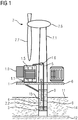
- FIG. 1 shows an embodiment of a substation 6 arranged on the foundation structure 9 of an offshore wind power plant 7 for an offshore wind farm.
- the substation 6 has a transformer 1 with a hermetically sealed housing 1.1, which is filled with an insulating liquid 1.5, and also a cooling system 1.8.
- the foundation structure 9 fixes the wind turbine 7 with its tower 7.1, the nacelle 7.6 and the rotor 7.7 attached to it in the seabed 12.
- a pipeline 5 which is equipped with a Buchholz relay 1.6, due to the thermally induced volume fluctuations of the insulating liquid 1.5, the same flows into a compression chamber 2.2, which is embedded in a hollow structure element 8 of the foundation structure 9.
- the compression chamber 2.2 is dimensioned such that space is formed above the changing level of the insulating liquid 3 for a gas cushion 4 which absorbs the volume fluctuations of the fluid.
- the pipeline 5 to the compression chamber 2.2 leads to the bottom of the same, so that filling of the connecting line to the transformer with insulating liquid 1.5, 3 is always ensured regardless of the fill level.
- the compression chamber 2.2 is arranged in a hollow structural element 8 of the foundation structure such that it is largely located below sea level 11.
- the hollow structure element 8 is filled with fresh water 15.
- the gas cushion 4 now largely assumes the temperature of the surrounding sea water 14. For example, the water temperature in large areas of the North Sea fluctuates only between 4 ° C and 18 ° C.
- the hermetically sealed transformer 1 can thus work with a drastically reduced pressure play.
- the compression chambers can be reduced significantly.
- FIG 2 shows an offshore substation 6, which is arranged on a platform, the foundation structure 9 of which is formed from a multi-part tubular structure.
- the expansion vessel system is formed by several separate expansion vessels 2.1, 2.2.
- the expansion vessel 2.1 is connected via a pipeline 5.5 to further compression chambers 2.2 for the gas cushion 4, which are arranged such that the gas cushion 4 is thermally decoupled from the temperature of the insulating liquid 1.5 in the transformer 1.
- both the expansion vessel 2.1 and the compression chamber 2.2 thermally decoupled from the transformer 1 are formed by sheet metal cylinders.
- FIG 3 shows an offshore substation 6 which is located on a platform.
- This platform is anchored to the sea floor 12 via tubular hollow structure elements 8.
- these hollow structural elements 8 are used to hold the expansion vessel system formed from an expansion vessel 2.1 and a compression chamber 2.2.
- a segment of the foundation structure 9 forms the compression chamber 2.2.
- the outer surface of the hollow structural element 8 forms part of the housing of the compression chamber 2.2.
- the gas cushion 4 is separated from the insulating liquid 3 by a membrane 2.5, which is arranged inside the expansion vessel 2.1 for the insulating liquid 3. This separation largely prevents the gas from the gas cushion 4 from dissolving in the insulating liquid 3.
- FIG 4 finally shows an embodiment in which an offshore substation 6 is integrated into the hollow structure receiving the tower 7.1 of a wind turbine 7.
- the substation 6 has several fluid-filled components (transformers 1 and chokes), each of which has its own expansion vessel 2.1 for the insulating liquid 3.
- the expansion vessels 2.1 are each connected on the gas side via pipes 5.5 to a common compression chamber 2.2. Accordingly, a plurality of transformers 1 use a common compression chamber 2.2 below sea level 11 to hold the compression gas 4, while maintaining the separation of the insulating liquids 1.5, 3.
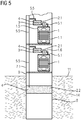
- FIG 5 also shows an embodiment in which a plurality of transformers 1 are arranged in the tower 7.1 or the foundation structure 9 of a wind turbine 7.
- the transformers 1 each have their own expansion tank 2.1.
- the expansion vessels 2.1 are connected via pipes 5.5 to a compression chamber 2.2 shared by a number of transformers 1.
- both the transformers 1 and the expansion vessel system with the compression chamber 2.2 are arranged within the foundation structure 9 or the tower 7.1 of a wind turbine 7.
- the cooling of the transformer 1 can be implemented via oil-water coolers as well as air coolers or radiators and is not shown in the exemplary embodiment.
- the wall of the foundation structure 9 at least partially represents the housing of the expansion vessel system or the compression chamber 2.2.
- FIG 6 shows an embodiment in which the expansion space for receiving the temperature-related volume fluctuations of the insulating liquid 1.5 is arranged within the transformer housing 1.1.
- the space not occupied by the insulating liquid, as well as the pipeline 5.5 and the compression chamber 2.2 of the expansion vessel system are filled with a gas cushion 4.
- the insulating liquid 1.5, 3 expands and displaces the gas through the pipeline 5.5 into the compression chamber 2.2 of the expansion vessel system. Since most of the gas is now inside the compression chamber 2.2 and due to the thermal coupling to the water temperature there are hardly any temperature fluctuations, the volume expansion coefficient of the gas can have little effect and has only a slight influence on the internal pressure of the transformer 1 and its expansion vessel system ,
Landscapes
- Engineering & Computer Science (AREA)
- Power Engineering (AREA)
- General Engineering & Computer Science (AREA)
- Combustion & Propulsion (AREA)
- Mechanical Engineering (AREA)
- Chemical & Material Sciences (AREA)
- Sustainable Development (AREA)
- Sustainable Energy (AREA)
- Life Sciences & Earth Sciences (AREA)
- Physics & Mathematics (AREA)
- Thermal Sciences (AREA)
- Civil Engineering (AREA)
- Structural Engineering (AREA)
- Wind Motors (AREA)
Claims (12)
- Ouvrage (6, 7) offshore, qui comprend une éolienne ayant un transformateur (1), qui comprend une cuve (1.1) emplie d'un liquide (1.5) isolant, comprenant, en outre, un système de vase de dilatation, dont le volume intérieur comprend un coussin (4) de gaz, la cuve (1.1) communiquant avec le système de vase de dilatation par une canalisation (5, 5.1, 5.5), cuve (1.1), canalisation (5, 5.1, 5.5) et système de vase de dilatation formant une unité résistante à la pression et fermée d'une manière hermétique, et dans lequel au moins une partie du coussin (4) de gaz est disposé en dessous du niveau (11) de la mer et le transformateur (1) au dessus du niveau (11) de la mer.
- Ouvrage (6, 7) offshore suivant la revendication 1, dans lequel tout le système de vase de dilatation est disposé en dessous du niveau (11) de la mer.
- Ouvrage (6, 7) offshore suivant l'une des revendications précédentes, dans lequel le système de vase de dilatation comprend un vase (2.1) de dilatation, comportant une partie ayant du liquide (3) isolant, la canalisation (5, 5.1) étant emplie de liquide et communiquant avec la partie ayant du liquide (3) isolant du vase (2.1) de dilatation, le système de vase de dilatation comprenant, en outre, une chambre (2.2) de compression communiquant avec la partie, contenue dans le vase (2.1) de dilatation, du coussin (4) de gaz par une canalisation (5.5) emplie de gaz, la chambre (2.2) de compression étant disposée en dessous du niveau (11) de la mer.
- Ouvrage (6, 7) offshore suivant la revendication 3, comprenant au moins un deuxième appareil (1) électrique, qui comprend une deuxième cuve (1.1) emplie d'un liquide (1.5) isolant, le système de vase de dilatation comprenant un deuxième vase (2.1) de dilatation, la deuxième cuve (1.1) communiquant par une deuxième canalisation (b, b.1) emplie de liquide avec un deuxième vase (2.1) de dilatation, contenant une deuxième partie ayant du liquide (3) isolant, du système de vase de dilatation, la partie, contenue dans le deuxième vase (2.1) de dilatation, du coussin (4) de gaz communiquant avec la chambre (2.2) de compression par une deuxième canalisation (5.5) emplie de gaz.
- Ouvrage (6, 7) offshore suivant la revendication 1 ou 2, dans lequel la canalisation (5.5) est emplie de gaz.
- Ouvrage (6, 7) offshore suivant la revendication 5, comprenant au moins un deuxième appareil (1) électrique, qui comprend une deuxième cuve (1.1) emplie d'un liquide (1.5) isolant, la deuxième cuve (1.1) communiquant avec le système de vase de dilatation par une canalisation (5.5) emplie de gaz.
- Ouvrage (6, 7) offshore suivant l'une des revendications précédentes, comprenant une pluralité de vases (2, 2.1) de dilatation et/ou de chambres (2.5) de compression communiquant entre eux.
- Ouvrage (6, 7) offshore suivant l'une des revendications précédentes, dans lequel la partie, disposée en dessous du niveau (11) de la mer, du coussin (4) de gaz, est disposée dans un élément (8) de structure creux de la structure (9) de base de l'ouvrage (6, 7) offshore.
- Ouvrage (6, 7) offshore suivant la revendication 8, dans lequel l'élément de structure creux forme, au moins en partie, une paroi enfermant le coussin de gaz.
- Ouvrage (6, 7) offshore suivant au moins la revendication 5 et 8, dans lequel un espace restant entre la chambre (2.2) de compression et l'élément (8) de structure creux est empli d'eau.
- Ouvrage (6, 7) offshore suivant au moins la revendication 3, dans lequel un vase (2, 2.1) de dilatation comprend une membrane (2.5), qui sépare le coussin de gaz et le liquide isolant.
- Ouvrage (6, 7) offshore suivant au moins la revendication 3, dans lequel la canalisation (5, 5.1) emplie de liquide a un relais (1.6) Buchholz.
Applications Claiming Priority (2)
| Application Number | Priority Date | Filing Date | Title |
|---|---|---|---|
| DE102016200800.5A DE102016200800B4 (de) | 2016-01-21 | 2016-01-21 | Offshorebauwerk |
| PCT/EP2016/082058 WO2017125236A1 (fr) | 2016-01-21 | 2016-12-21 | Ouvrage offshore |
Publications (2)
| Publication Number | Publication Date |
|---|---|
| EP3380676A1 EP3380676A1 (fr) | 2018-10-03 |
| EP3380676B1 true EP3380676B1 (fr) | 2020-02-19 |
Family
ID=57758600
Family Applications (1)
| Application Number | Title | Priority Date | Filing Date |
|---|---|---|---|
| EP16823268.4A Active EP3380676B1 (fr) | 2016-01-21 | 2016-12-21 | Ouvrage offshore |
Country Status (5)
| Country | Link |
|---|---|
| US (1) | US20190334325A1 (fr) |
| EP (1) | EP3380676B1 (fr) |
| CN (1) | CN108474189B (fr) |
| DE (1) | DE102016200800B4 (fr) |
| WO (1) | WO2017125236A1 (fr) |
Families Citing this family (11)
| Publication number | Priority date | Publication date | Assignee | Title |
|---|---|---|---|---|
| EP3491240B1 (fr) * | 2016-09-09 | 2025-01-01 | Siemens Gamesa Renewable Energy A/S | Pièce de transition pour éolienne |
| WO2020098889A1 (fr) * | 2018-11-14 | 2020-05-22 | Vestas Wind Systems A/S | Éolienne et procédé de maintenance d'éolienne |
| CN109638698B (zh) * | 2018-11-23 | 2025-02-25 | 上海勘测设计研究院有限公司 | 分布式模块化海上变电站 |
| CN109412039A (zh) * | 2018-11-28 | 2019-03-01 | 人民电器集团上海有限公司 | 一种配电箱绝缘防护装置 |
| CN110130378B (zh) * | 2019-05-14 | 2019-12-27 | 长江水利委员会长江科学院 | 一种新型植入式减压井降压排水系统及方法 |
| EP3770427A1 (fr) * | 2019-07-22 | 2021-01-27 | Siemens Gamesa Renewable Energy A/S | Système de transformateur de turbine d'éolienne |
| CN110374828B (zh) * | 2019-08-01 | 2021-02-19 | 段传香 | 一种具有散热功能的安全可靠性高的海上风力发电设备 |
| PL246060B1 (pl) * | 2021-05-24 | 2024-11-25 | Berent Piotr | Monopal fundamentowy i sposób posadowienia monopala fundamentowego |
| CN114396363B (zh) * | 2022-01-19 | 2022-08-30 | 山东德瑞防腐材料有限公司 | 一种带牺牲阳极阴极防腐蚀保护与监测装置的海上风机 |
| GB202207254D0 (en) * | 2022-05-18 | 2022-06-29 | Aquaterra Energy Ltd | A heat-exchanger |
| CN116123036B (zh) * | 2023-02-17 | 2026-05-12 | 山东南海气囊工程有限公司 | 升降式海上风力发电站 |
Family Cites Families (8)
| Publication number | Priority date | Publication date | Assignee | Title |
|---|---|---|---|---|
| GB2317686B (en) * | 1996-09-26 | 2000-09-27 | Gec Alsthom Ltd | Power equipment for use underwater |
| NO313068B1 (no) * | 2000-11-14 | 2002-08-05 | Abb As | Undersjoisk transformator - distribusjonssystem med et forste og et andre kammer |
| DE102004063508B4 (de) * | 2004-12-27 | 2008-10-16 | Siemens Ag | Elektrisches Bauteil mit Kühlkreislauf für den Unterwasserbetrieb |
| CN201956160U (zh) * | 2010-12-16 | 2011-08-31 | 保定天威集团有限公司 | 气体绝缘变压器的冷却装置 |
| JP5492832B2 (ja) * | 2011-07-25 | 2014-05-14 | 株式会社日立産機システム | 変圧器及び風力発電システム |
| CN202501648U (zh) * | 2011-12-31 | 2012-10-24 | 徐霆生 | 陆上或海上风力发电设施的地源或水源冷却和加热系统 |
| EP2733265B1 (fr) * | 2012-11-14 | 2018-01-03 | Siemens Aktiengesellschaft | Installation de refroidissement pour une plateforme de transformation |
| CN103996498B (zh) * | 2014-06-11 | 2016-08-31 | 中国能建集团装备有限公司南京技术中心 | 一种海上变电站主变压器海水冷却系统 |
-
2016
- 2016-01-21 DE DE102016200800.5A patent/DE102016200800B4/de not_active Expired - Fee Related
- 2016-12-21 EP EP16823268.4A patent/EP3380676B1/fr active Active
- 2016-12-21 WO PCT/EP2016/082058 patent/WO2017125236A1/fr not_active Ceased
- 2016-12-21 CN CN201680079288.3A patent/CN108474189B/zh not_active Expired - Fee Related
- 2016-12-21 US US16/070,798 patent/US20190334325A1/en not_active Abandoned
Non-Patent Citations (1)
| Title |
|---|
| None * |
Also Published As
| Publication number | Publication date |
|---|---|
| WO2017125236A1 (fr) | 2017-07-27 |
| US20190334325A1 (en) | 2019-10-31 |
| DE102016200800A1 (de) | 2017-07-27 |
| CN108474189B (zh) | 2021-07-30 |
| CN108474189A (zh) | 2018-08-31 |
| DE102016200800B4 (de) | 2017-08-17 |
| EP3380676A1 (fr) | 2018-10-03 |
Similar Documents
| Publication | Publication Date | Title |
|---|---|---|
| DE102016200800B4 (de) | Offshorebauwerk | |
| EP1831901B1 (fr) | Composant electrique a circuit de refroidissement pour une utilisation sous-marine | |
| DE60131072T2 (de) | Schwimmende offshore-windkraftanlage | |
| DE69727484T2 (de) | Leistungsanlage zur unterwasserbenutzung | |
| DE202014004373U1 (de) | ln die Gründungsstruktur eines Offshore-Bauwerkes integriertes Umspannwerk für Windparks | |
| DE102015002654B4 (de) | Verfahren und Vorrichtuung zur Speicherung eines Energieträgermediums | |
| EP2811160A1 (fr) | Installation de production d'énergie éolienne en mer | |
| DE202014004372U1 (de) | Offshore Windpark mit mindestens einem seeseitigen Umspannwerk | |
| WO2020001932A1 (fr) | Corps flottant, éolienne et parc éolien de haute mer | |
| EP2811159B1 (fr) | Installation de production d'énergie éolienne en mer | |
| EP3280912B1 (fr) | Éolienne à circuit de liquide et composants associés | |
| EP3884552B1 (fr) | Dispositif de refroidissement sous l'eau | |
| EP2733266B1 (fr) | Plateforme de transformation avec installation de refroidissement | |
| EP3506441B1 (fr) | Poste électrique | |
| EP2237384A2 (fr) | Système de refroidissement pour une station de transformation électrique, notamment pour une éolienne | |
| EP2733265B1 (fr) | Installation de refroidissement pour une plateforme de transformation | |
| DE2249690B2 (de) | Sicherheitseinrichtung fuer unter druck stehende anlagen | |
| EP1410402B1 (fr) | Dispositif de commande pour un circuit de refroidissement | |
| DE202020100895U1 (de) | Thermischer Energiespeicher, insbesondere Mehrzonenspeicher in Form eines Flachbodentanks | |
| DE102018210620A1 (de) | Schwimmkörper zum Tragen einer energetischen Anlage | |
| DE3111887C2 (de) | Unterwasserstation | |
| WO2010029015A2 (fr) | Centrale hydraulique | |
| DE2739103A1 (de) | Kuehl- und heizsystem fuer ein mit geraeten bestuecktes gehaeuse | |
| DE20113633U1 (de) | Wärmespeicher und Heizanlage | |
| DE102008055778A1 (de) | Offshore Gründung und Verfahren zur Montage |
Legal Events
| Date | Code | Title | Description |
|---|---|---|---|
| STAA | Information on the status of an ep patent application or granted ep patent |
Free format text: STATUS: UNKNOWN |
|
| STAA | Information on the status of an ep patent application or granted ep patent |
Free format text: STATUS: THE INTERNATIONAL PUBLICATION HAS BEEN MADE |
|
| PUAI | Public reference made under article 153(3) epc to a published international application that has entered the european phase |
Free format text: ORIGINAL CODE: 0009012 |
|
| STAA | Information on the status of an ep patent application or granted ep patent |
Free format text: STATUS: REQUEST FOR EXAMINATION WAS MADE |
|
| 17P | Request for examination filed |
Effective date: 20180622 |
|
| AK | Designated contracting states |
Kind code of ref document: A1 Designated state(s): AL AT BE BG CH CY CZ DE DK EE ES FI FR GB GR HR HU IE IS IT LI LT LU LV MC MK MT NL NO PL PT RO RS SE SI SK SM TR |
|
| AX | Request for extension of the european patent |
Extension state: BA ME |
|
| STAA | Information on the status of an ep patent application or granted ep patent |
Free format text: STATUS: EXAMINATION IS IN PROGRESS |
|
| 17Q | First examination report despatched |
Effective date: 20190227 |
|
| DAV | Request for validation of the european patent (deleted) | ||
| DAX | Request for extension of the european patent (deleted) | ||
| GRAP | Despatch of communication of intention to grant a patent |
Free format text: ORIGINAL CODE: EPIDOSNIGR1 |
|
| STAA | Information on the status of an ep patent application or granted ep patent |
Free format text: STATUS: GRANT OF PATENT IS INTENDED |
|
| INTG | Intention to grant announced |
Effective date: 20190930 |
|
| GRAS | Grant fee paid |
Free format text: ORIGINAL CODE: EPIDOSNIGR3 |
|
| GRAA | (expected) grant |
Free format text: ORIGINAL CODE: 0009210 |
|
| STAA | Information on the status of an ep patent application or granted ep patent |
Free format text: STATUS: THE PATENT HAS BEEN GRANTED |
|
| AK | Designated contracting states |
Kind code of ref document: B1 Designated state(s): AL AT BE BG CH CY CZ DE DK EE ES FI FR GB GR HR HU IE IS IT LI LT LU LV MC MK MT NL NO PL PT RO RS SE SI SK SM TR |
|
| REG | Reference to a national code |
Ref country code: CH Ref legal event code: EP |
|
| REG | Reference to a national code |
Ref country code: DE Ref legal event code: R096 Ref document number: 502016008865 Country of ref document: DE |
|
| REG | Reference to a national code |
Ref country code: AT Ref legal event code: REF Ref document number: 1235102 Country of ref document: AT Kind code of ref document: T Effective date: 20200315 |
|
| REG | Reference to a national code |
Ref country code: IE Ref legal event code: FG4D Free format text: LANGUAGE OF EP DOCUMENT: GERMAN |
|
| REG | Reference to a national code |
Ref country code: NO Ref legal event code: T2 Effective date: 20200219 |
|
| REG | Reference to a national code |
Ref country code: NL Ref legal event code: MP Effective date: 20200219 |
|
| PG25 | Lapsed in a contracting state [announced via postgrant information from national office to epo] |
Ref country code: RS Free format text: LAPSE BECAUSE OF FAILURE TO SUBMIT A TRANSLATION OF THE DESCRIPTION OR TO PAY THE FEE WITHIN THE PRESCRIBED TIME-LIMIT Effective date: 20200219 Ref country code: FI Free format text: LAPSE BECAUSE OF FAILURE TO SUBMIT A TRANSLATION OF THE DESCRIPTION OR TO PAY THE FEE WITHIN THE PRESCRIBED TIME-LIMIT Effective date: 20200219 |
|
| REG | Reference to a national code |
Ref country code: LT Ref legal event code: MG4D |
|
| PG25 | Lapsed in a contracting state [announced via postgrant information from national office to epo] |
Ref country code: GR Free format text: LAPSE BECAUSE OF FAILURE TO SUBMIT A TRANSLATION OF THE DESCRIPTION OR TO PAY THE FEE WITHIN THE PRESCRIBED TIME-LIMIT Effective date: 20200520 Ref country code: LV Free format text: LAPSE BECAUSE OF FAILURE TO SUBMIT A TRANSLATION OF THE DESCRIPTION OR TO PAY THE FEE WITHIN THE PRESCRIBED TIME-LIMIT Effective date: 20200219 Ref country code: SE Free format text: LAPSE BECAUSE OF FAILURE TO SUBMIT A TRANSLATION OF THE DESCRIPTION OR TO PAY THE FEE WITHIN THE PRESCRIBED TIME-LIMIT Effective date: 20200219 Ref country code: HR Free format text: LAPSE BECAUSE OF FAILURE TO SUBMIT A TRANSLATION OF THE DESCRIPTION OR TO PAY THE FEE WITHIN THE PRESCRIBED TIME-LIMIT Effective date: 20200219 Ref country code: BG Free format text: LAPSE BECAUSE OF FAILURE TO SUBMIT A TRANSLATION OF THE DESCRIPTION OR TO PAY THE FEE WITHIN THE PRESCRIBED TIME-LIMIT Effective date: 20200519 Ref country code: IS Free format text: LAPSE BECAUSE OF FAILURE TO SUBMIT A TRANSLATION OF THE DESCRIPTION OR TO PAY THE FEE WITHIN THE PRESCRIBED TIME-LIMIT Effective date: 20200619 |
|
| PG25 | Lapsed in a contracting state [announced via postgrant information from national office to epo] |
Ref country code: NL Free format text: LAPSE BECAUSE OF FAILURE TO SUBMIT A TRANSLATION OF THE DESCRIPTION OR TO PAY THE FEE WITHIN THE PRESCRIBED TIME-LIMIT Effective date: 20200219 |
|
| PG25 | Lapsed in a contracting state [announced via postgrant information from national office to epo] |
Ref country code: DK Free format text: LAPSE BECAUSE OF FAILURE TO SUBMIT A TRANSLATION OF THE DESCRIPTION OR TO PAY THE FEE WITHIN THE PRESCRIBED TIME-LIMIT Effective date: 20200219 Ref country code: SM Free format text: LAPSE BECAUSE OF FAILURE TO SUBMIT A TRANSLATION OF THE DESCRIPTION OR TO PAY THE FEE WITHIN THE PRESCRIBED TIME-LIMIT Effective date: 20200219 Ref country code: EE Free format text: LAPSE BECAUSE OF FAILURE TO SUBMIT A TRANSLATION OF THE DESCRIPTION OR TO PAY THE FEE WITHIN THE PRESCRIBED TIME-LIMIT Effective date: 20200219 Ref country code: PT Free format text: LAPSE BECAUSE OF FAILURE TO SUBMIT A TRANSLATION OF THE DESCRIPTION OR TO PAY THE FEE WITHIN THE PRESCRIBED TIME-LIMIT Effective date: 20200712 Ref country code: RO Free format text: LAPSE BECAUSE OF FAILURE TO SUBMIT A TRANSLATION OF THE DESCRIPTION OR TO PAY THE FEE WITHIN THE PRESCRIBED TIME-LIMIT Effective date: 20200219 Ref country code: SK Free format text: LAPSE BECAUSE OF FAILURE TO SUBMIT A TRANSLATION OF THE DESCRIPTION OR TO PAY THE FEE WITHIN THE PRESCRIBED TIME-LIMIT Effective date: 20200219 Ref country code: ES Free format text: LAPSE BECAUSE OF FAILURE TO SUBMIT A TRANSLATION OF THE DESCRIPTION OR TO PAY THE FEE WITHIN THE PRESCRIBED TIME-LIMIT Effective date: 20200219 Ref country code: CZ Free format text: LAPSE BECAUSE OF FAILURE TO SUBMIT A TRANSLATION OF THE DESCRIPTION OR TO PAY THE FEE WITHIN THE PRESCRIBED TIME-LIMIT Effective date: 20200219 Ref country code: LT Free format text: LAPSE BECAUSE OF FAILURE TO SUBMIT A TRANSLATION OF THE DESCRIPTION OR TO PAY THE FEE WITHIN THE PRESCRIBED TIME-LIMIT Effective date: 20200219 |
|
| REG | Reference to a national code |
Ref country code: DE Ref legal event code: R097 Ref document number: 502016008865 Country of ref document: DE |
|
| PLBE | No opposition filed within time limit |
Free format text: ORIGINAL CODE: 0009261 |
|
| STAA | Information on the status of an ep patent application or granted ep patent |
Free format text: STATUS: NO OPPOSITION FILED WITHIN TIME LIMIT |
|
| 26N | No opposition filed |
Effective date: 20201120 |
|
| RAP2 | Party data changed (patent owner data changed or rights of a patent transferred) |
Owner name: SIEMENS ENERGY GLOBAL GMBH & CO. KG |
|
| PG25 | Lapsed in a contracting state [announced via postgrant information from national office to epo] |
Ref country code: IT Free format text: LAPSE BECAUSE OF FAILURE TO SUBMIT A TRANSLATION OF THE DESCRIPTION OR TO PAY THE FEE WITHIN THE PRESCRIBED TIME-LIMIT Effective date: 20200219 |
|
| PG25 | Lapsed in a contracting state [announced via postgrant information from national office to epo] |
Ref country code: PL Free format text: LAPSE BECAUSE OF FAILURE TO SUBMIT A TRANSLATION OF THE DESCRIPTION OR TO PAY THE FEE WITHIN THE PRESCRIBED TIME-LIMIT Effective date: 20200219 Ref country code: SI Free format text: LAPSE BECAUSE OF FAILURE TO SUBMIT A TRANSLATION OF THE DESCRIPTION OR TO PAY THE FEE WITHIN THE PRESCRIBED TIME-LIMIT Effective date: 20200219 |
|
| REG | Reference to a national code |
Ref country code: CH Ref legal event code: NV Representative=s name: SIEMENS SCHWEIZ AG, CH |
|
| REG | Reference to a national code |
Ref country code: DE Ref legal event code: R119 Ref document number: 502016008865 Country of ref document: DE |
|
| REG | Reference to a national code |
Ref country code: CH Ref legal event code: PL |
|
| PG25 | Lapsed in a contracting state [announced via postgrant information from national office to epo] |
Ref country code: MC Free format text: LAPSE BECAUSE OF FAILURE TO SUBMIT A TRANSLATION OF THE DESCRIPTION OR TO PAY THE FEE WITHIN THE PRESCRIBED TIME-LIMIT Effective date: 20200219 |
|
| REG | Reference to a national code |
Ref country code: BE Ref legal event code: MM Effective date: 20201231 |
|
| PG25 | Lapsed in a contracting state [announced via postgrant information from national office to epo] |
Ref country code: LU Free format text: LAPSE BECAUSE OF NON-PAYMENT OF DUE FEES Effective date: 20201221 Ref country code: FR Free format text: LAPSE BECAUSE OF NON-PAYMENT OF DUE FEES Effective date: 20201231 Ref country code: IE Free format text: LAPSE BECAUSE OF NON-PAYMENT OF DUE FEES Effective date: 20201221 |
|
| PG25 | Lapsed in a contracting state [announced via postgrant information from national office to epo] |
Ref country code: LI Free format text: LAPSE BECAUSE OF NON-PAYMENT OF DUE FEES Effective date: 20201231 Ref country code: CH Free format text: LAPSE BECAUSE OF NON-PAYMENT OF DUE FEES Effective date: 20201231 Ref country code: DE Free format text: LAPSE BECAUSE OF NON-PAYMENT OF DUE FEES Effective date: 20210701 |
|
| REG | Reference to a national code |
Ref country code: GB Ref legal event code: 732E Free format text: REGISTERED BETWEEN 20211202 AND 20211209 |
|
| PGFP | Annual fee paid to national office [announced via postgrant information from national office to epo] |
Ref country code: NO Payment date: 20211209 Year of fee payment: 6 |
|
| PGFP | Annual fee paid to national office [announced via postgrant information from national office to epo] |
Ref country code: GB Payment date: 20220119 Year of fee payment: 6 |
|
| PG25 | Lapsed in a contracting state [announced via postgrant information from national office to epo] |
Ref country code: TR Free format text: LAPSE BECAUSE OF FAILURE TO SUBMIT A TRANSLATION OF THE DESCRIPTION OR TO PAY THE FEE WITHIN THE PRESCRIBED TIME-LIMIT Effective date: 20200219 Ref country code: MT Free format text: LAPSE BECAUSE OF FAILURE TO SUBMIT A TRANSLATION OF THE DESCRIPTION OR TO PAY THE FEE WITHIN THE PRESCRIBED TIME-LIMIT Effective date: 20200219 Ref country code: CY Free format text: LAPSE BECAUSE OF FAILURE TO SUBMIT A TRANSLATION OF THE DESCRIPTION OR TO PAY THE FEE WITHIN THE PRESCRIBED TIME-LIMIT Effective date: 20200219 |
|
| PG25 | Lapsed in a contracting state [announced via postgrant information from national office to epo] |
Ref country code: MK Free format text: LAPSE BECAUSE OF FAILURE TO SUBMIT A TRANSLATION OF THE DESCRIPTION OR TO PAY THE FEE WITHIN THE PRESCRIBED TIME-LIMIT Effective date: 20200219 Ref country code: AL Free format text: LAPSE BECAUSE OF FAILURE TO SUBMIT A TRANSLATION OF THE DESCRIPTION OR TO PAY THE FEE WITHIN THE PRESCRIBED TIME-LIMIT Effective date: 20200219 |
|
| PG25 | Lapsed in a contracting state [announced via postgrant information from national office to epo] |
Ref country code: BE Free format text: LAPSE BECAUSE OF NON-PAYMENT OF DUE FEES Effective date: 20201231 |
|
| REG | Reference to a national code |
Ref country code: AT Ref legal event code: MM01 Ref document number: 1235102 Country of ref document: AT Kind code of ref document: T Effective date: 20211221 |
|
| PG25 | Lapsed in a contracting state [announced via postgrant information from national office to epo] |
Ref country code: AT Free format text: LAPSE BECAUSE OF NON-PAYMENT OF DUE FEES Effective date: 20211221 |
|
| REG | Reference to a national code |
Ref country code: NO Ref legal event code: MMEP |
|
| GBPC | Gb: european patent ceased through non-payment of renewal fee |
Effective date: 20221221 |
|
| PG25 | Lapsed in a contracting state [announced via postgrant information from national office to epo] |
Ref country code: NO Free format text: LAPSE BECAUSE OF NON-PAYMENT OF DUE FEES Effective date: 20221231 Ref country code: GB Free format text: LAPSE BECAUSE OF NON-PAYMENT OF DUE FEES Effective date: 20221221 |