EP3380699B1 - Werkzeug und verfahren für stufenweise zementierung - Google Patents
Werkzeug und verfahren für stufenweise zementierung Download PDFInfo
- Publication number
- EP3380699B1 EP3380699B1 EP16723580.3A EP16723580A EP3380699B1 EP 3380699 B1 EP3380699 B1 EP 3380699B1 EP 16723580 A EP16723580 A EP 16723580A EP 3380699 B1 EP3380699 B1 EP 3380699B1
- Authority
- EP
- European Patent Office
- Prior art keywords
- inner mandrel
- well tool
- tool
- fluid
- fluid pressure
- Prior art date
- Legal status (The legal status is an assumption and is not a legal conclusion. Google has not performed a legal analysis and makes no representation as to the accuracy of the status listed.)
- Active
Links
Images


Classifications
-
- E—FIXED CONSTRUCTIONS
- E21—EARTH OR ROCK DRILLING; MINING
- E21B—EARTH OR ROCK DRILLING; OBTAINING OIL, GAS, WATER, SOLUBLE OR MELTABLE MATERIALS OR A SLURRY OF MINERALS FROM WELLS
- E21B33/00—Sealing or packing boreholes or wells
- E21B33/10—Sealing or packing boreholes or wells in the borehole
- E21B33/13—Methods or devices for cementing, for plugging holes, crevices or the like
- E21B33/14—Methods or devices for cementing, for plugging holes, crevices or the like for cementing casings into boreholes
- E21B33/146—Stage cementing, i.e. discharging cement from casing at different levels
-
- E—FIXED CONSTRUCTIONS
- E21—EARTH OR ROCK DRILLING; MINING
- E21B—EARTH OR ROCK DRILLING; OBTAINING OIL, GAS, WATER, SOLUBLE OR MELTABLE MATERIALS OR A SLURRY OF MINERALS FROM WELLS
- E21B33/00—Sealing or packing boreholes or wells
- E21B33/10—Sealing or packing boreholes or wells in the borehole
- E21B33/12—Packers; Plugs
- E21B33/128—Packers; Plugs with a member expanded radially by axial pressure
-
- E—FIXED CONSTRUCTIONS
- E21—EARTH OR ROCK DRILLING; MINING
- E21B—EARTH OR ROCK DRILLING; OBTAINING OIL, GAS, WATER, SOLUBLE OR MELTABLE MATERIALS OR A SLURRY OF MINERALS FROM WELLS
- E21B33/00—Sealing or packing boreholes or wells
- E21B33/10—Sealing or packing boreholes or wells in the borehole
- E21B33/12—Packers; Plugs
- E21B33/128—Packers; Plugs with a member expanded radially by axial pressure
- E21B33/1285—Packers; Plugs with a member expanded radially by axial pressure by fluid pressure
-
- E—FIXED CONSTRUCTIONS
- E21—EARTH OR ROCK DRILLING; MINING
- E21B—EARTH OR ROCK DRILLING; OBTAINING OIL, GAS, WATER, SOLUBLE OR MELTABLE MATERIALS OR A SLURRY OF MINERALS FROM WELLS
- E21B34/00—Valve arrangements for boreholes or wells
- E21B34/06—Valve arrangements for boreholes or wells in wells
- E21B34/10—Valve arrangements for boreholes or wells in wells operated by control fluid supplied from outside the borehole
-
- E—FIXED CONSTRUCTIONS
- E21—EARTH OR ROCK DRILLING; MINING
- E21B—EARTH OR ROCK DRILLING; OBTAINING OIL, GAS, WATER, SOLUBLE OR MELTABLE MATERIALS OR A SLURRY OF MINERALS FROM WELLS
- E21B2200/00—Special features related to earth drilling for obtaining oil, gas or water
- E21B2200/06—Sleeve valves
Definitions
- This disclosure relates to well tools for use in completing a wellbore, and more particularly to stage cementing well tools.
- Stage cementing is used in well operations to form cased and cemented wellbores in stages.
- a stage cementing well tool operates to supply cement to an annulus of awellbore at a location within a wellbore above a bottomhole assembly.
- stage cementing well tools can be utilized when a single stage cement process is faulty, incomplete, or otherwise unsatisfactory and requires additional cement to form a cemented casing.
- a stage cementing well tool disposed in a well includes a packer element and cementing ports to flow cement into an annulus of the well.
- US 2012/0261127 describes a downhole tool provided within a casing string for use in cement staging operations.
- the tool includes a sleeve in the tool that selectively slides downward under pressure to expose ports formed in a side wall of the tool. Also, an annulus through the tool is selectively blocked so that cement in the casing string flows radially outward through the ports and into an annulus between the tool and a wellbore.
- An inflatable packer is included that is integral to the body of the tool and is inflated with a fluid that is pushed into the packer as the sleeve slides downward.
- US 5,279,370 describes a cementing tool, and more particularly a stage packer collar, having a tubular housing with an inner passage defined longitudinally therethrough and having a radially outer surface.
- US 8,800,655 describes a mechanical stage cementing tool that includes a mechanical opening and closing seat sleeve and a pin sub.
- the mechanical stage cementing tool may be converted to a hydraulic stage cementing tool by inserting a hydraulic tube assembly into the mechanical opening and closing seat sleeve at a hydraulic modification area and by adding a hydraulic seat to the pin sub.
- the stage cementing tool has a running-in-hole position, an open position, and a closed position.
- This disclosure describes stage cementing tools and methods in well bore cementing.
- This disclosure describes a stage cementing well tool that selectively opens and closes flow ports that fluidly connect a central bore of the stage cementing well tool and an exterior of the well tool.
- the flow ports can be selectively controlled (e.g., opened and closed) to allow the flow of fluid (e.g., cement, slurry, and/or other) from the central bore of the well tool out to the exterior of the well tool, for example, to form a casing in the wellbore.
- the opening and closing of the flow ports can be controlled in response to fluid pressure (e.g., hydraulic pressure) within the central bore of the well tool, or an operating tool to manually open the flow ports.
- a work string fluidly coupled to the central bore of the well tool can be pressured up to open the flow ports in the well tool and allow cement, concrete slurry, or other fluid fed through the work string to disperse into the well annulus through the open flow ports.
- the central bore pressure can be decreased (e.g., at the well surface) to close the flow ports in the well tool.
- the stage cementing well tool is free from plug seats and can include a full-bore pass through, for example, free from other obstructions that reduce or otherwise obstruct a diameter of the central bore of the well tool.
- the stage cementing well tool includes a sealing element (e.g., packer element, such as a mechanical packer, inflatable packer, swellable packer, and/or other) that can be set in response to the same fluid pressure or operating tool used to selectively open the flow ports.
- a sealing element e.g., packer element, such as a mechanical packer, inflatable packer, swellable packer, and/or other
- a plug seat along the central bore of the well tool is required to seal with a plug (e.g., dropped ball or landing/opening plug) in order to hydraulically activate some element of the conventional stage cementing well tool, such as a packer setting element or flow port element.
- a plug e.g., dropped ball or landing/opening plug
- This disclosure describes a stage cementing well tool with a mandrel that is free from plug seats and movable to open flow ports in response to pressure within the central bore of the well tool.
- the stage cementing well tool has a full-bore pass through, for example, where the central bore is free from obstructions along the longitudinal length of the well tool. There are no plugs or plug seats to drill out after a stage cementing operation using the stage cementing well tool.
- the stage cementing well tool can hydraulically open and close flow ports without the use of a plug and plug seat within the central bore of the well tool.
- operation of the stage cementing well tool to selectively control the flow ports and/or set a packer element is not affected by the wellbore angle or deviation of the wellbore in which the well tool is disposed.
- a sealing element e.g., packer element
- a sealing element of the stage cementing well tool can be tested after it is set.
- a stage cementing well tool of this disclosure allows for a mechanical option of operating (e.g., moving) the mandrel, for example, using a dedicated operating tool or setting tool.
- This mechanical option can effectively deal with the potential situation that casing float equipment on a bottom section of a well string fails to maintain casing pressure integrity, for example, during a first stage cementing operation.
- the stage cementing well tool design of this disclosure provides the advantage of a full-bore pass through where no drill-out operation is required, where conventional stage cementing tools do require this drill-out operation.
- stage cementing well tools of the present disclosure provide little to no risk of potentially damaging or causing a leak point across the stage cementing tool from drill-out procedures of plugs and/or plug seats, as compared to these risks being present in conventional stage cementing tools and primary-stage cementing tools.
- a full-bore pass through of stage cementing tools better facilitates run-in of multiple stage cementing tools in a casing string, for example, to effectively and efficiently deal with loss zones in an open-hole section for the purpose of achieving better well integrity (e.g., as each stage cementing tool can be individually operated by a dedicated setting tool on an inner work string or its own threshold activation pressure).
- cementing casing is an important operation in well construction, and in some instances, cementing casing is a one-shot opportunity where if something goes wrong, the consequence and/or remedial procedures can be very costly.
- the well tools and procedures of this disclosure avoid these kinds of operational risks.
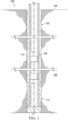
- FIG. 1 is a schematic partial cross-sectional view of an example well system 100 that generally includes a substantially cylindrical wellbore 102 extending from a well head (not shown) at a surface 104 downward into the Earth into one or more subterranean zones of interest 106 (one shown).
- a well string 108 is shown as having been lowered from the surface 104 into the wellbore 102.
- casing 110 a portion of the wellbore 102 is lined with lengths of tubing, called casing 110.
- the casing 110 can make up an outer tubing layer of the well string 108, for example, during a cementing operation.
- the casing 110 includes a series of jointed lengths of tubing coupled together end-to-end and/or a continuous (e.g., not jointed) coiled tubing.
- the well string 108 is a work string including cementing well tools 112 (two shown) disposed along a longitudinal length of the well string 108.
- the number and location of the cementing tools 112 can vary along the longitudinal length, for example, based on well cementing operations, well orientation, and/or other factors.
- the well string 108 can include one or more cementing well tools 112 disposed at a wellbore location corresponding to a start location of a stage cementing operation.
- the wellbore 102 has been drilled, and a first cementing operation has been performed to create a base cement 114 at a downhole location of the wellbore 102.
- the wellbore 102 can be drilled in stages, and cement with a corresponding casing can be installed between stages.
- the stage cementing well tools 112 are used to inject cement in stages between the casing 110 and inner walls of the wellbore 102, or between an existing casing and an outer tubular housing of the well tool(s) 112.
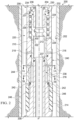
- FIG. 2 is a schematic partial cross-sectional view of an example stage cementing well tool 200 in a wellbore 202.
- the stage cementing well tool 200 can be used in one of the cementing well tools 112 of the well system 100 of FIG. 1 .
- the example well tool 200 is disposed within the wellbore 202 substantially along longitudinal axis A-A, and includes a central bore 204 extending between an uphole end 206 and a downhole end 208 with respect to the wellbore 202.
- the example well tool 200 includes a tubular housing 210, a movable inner mandrel 212 disposed within the tubular housing 210, a sealing element 214 circumscribing a portion of the tubular housing 210 proximate the downhole end 208 of the well tool 200, and a movable setting sleeve 216 operable to set the sealing element 214.
- the inner mandrel 212 is selectively movable between a first, closed position and a second, open position in response to a pressure, such as a fluid pressure (e.g., hydraulic pressure), in the central bore 204 of the well tool 200.
- a pressure such as a fluid pressure (e.g., hydraulic pressure)
- the position of the inner mandrel 212 allows for control of fluid flow between the central bore 204 and an annulus 220 between the well tool 200 and the wellbore 202 walls by opening or closing flow ports through the well tool 200 (e.g., between an interior and exterior of the well tool 200).
- the setting sleeve 216 is movable between a first, retracted position and a second, expanded position in response to movement of the inner mandrel 212.
- FIG. 2 shows the sealing element 214 in the first, closed position and the setting sleeve 216 in the first, retracted position.
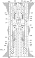
- FIG. 4 is a schematic partial cross-sectional view of the example stage cementing well tool 200 of FIG. 2 , where FIG. 4 depicts the inner mandrel 212 in the second, open position, and depicts the setting sleeve in the second, expanded position with the packer element set, for example, in an activated, sealing state.
- the housing 210 includes a housing port 218 through a wall of the housing 210.
- the inner mandrel 212 in the first, closed position closes (e.g., plugs, seals, or otherwise blocks) the housing port 218 from fluid flow between the central bore 204 and the annulus 220 between the well tool 200 and the wellbore 202 walls.
- the inner mandrel 212 also includes a passage 222 through a wall of the inner mandrel 212.
- the passage is misaligned with the housing port 218 when the inner mandrel 212 is in the first, closed position, as shown in FIG. 2 .
- the passage is aligned with the housing port 218 when the inner mandrel 212 is in the second, open position, as shown in FIG. 4 , for example, to allow fluid flow from the central bore 204 out into the annulus 220.
- the inner mandrel 212 is substantially tubular, and resides substantially along and partially against an inner surface of the tubular housing 210.
- a biasing element e.g., biasing spring 224 between the inner mandrel 212 and the tubular housing 210 biases the inner mandrel 212 toward the first, closed position.
- the biasing element includes a spring 224 that resides in a spring chamber 226 between a portion of an outer surface of the inner mandrel 212 and an inner surface of the tubular housing 210, where the spring 224 acts on corresponding shoulders of the inner mandrel 212 and tubular housing 210 to bias the inner mandrel 212 toward the first, closed position relative to the tubular housing 210.
- the tubular housing 210 can include a pressure release vent 228 from the spring chamber 226, for example, to equalize or release pressure in the spring chamber 226 during operation.
- the housing 210 includes a fluid inlet port 230 (two shown in FIGS. 2 and 4 ) fluidly coupling the central bore 204 with a fluid pressure chamber 232 in the tubular housing 210, where a first surface 234 of the inner mandrel 212 is exposed to the fluid pressure chamber 232.
- the fluid inlet port 230 allows pressure in the central bore 204, such as fluid hydraulic pressure, to act against the first surface 234 of the inner mandrel 212 in a direction parallel to the longitudinal axis A-A.
- the position of the inner mandrel 212 is based at least in part on a resultant force on the first surface 234 from the central bore pressure and the spring force from the biasing spring 224.
- the biasing spring 224 acts against the resultant force.
- the resultant force is less than the spring force, and the inner mandrel 212 is biased to move to the first, closed position.
- the resultant force is greater than the spring force, and the inner mandrel 212 is forced toward the second, open position.
- the inner mandrel 212 and/or the tubular housing 210 includes a stop surface, such as an end surface, shoulder, protrusion, or other element, to hold the inner mandrel 212 in the second, open position such that the passage 222 and the housing port 218 are aligned.
- the fluid inlet port 230 includes a filter 236, for example, to prevent solids or other contaminants in the central bore 204 from entering the fluid pressure chamber 232.
- the first surface 234 is shown in FIGS. 2 and 4 as an uphole end of the inner mandrel 212. However, the surface can be a different surface of the inner mandrel 212 that allows fluid pressure from the fluid pressure chamber 232 to act on the inner mandrel 212.
- the setting sleeve 216 activates the packer element 214, for example, to set the packer element 214.
- the setting sleeve 216 is substantially tubular and is movable between a first, retracted position, as shown in FIG. 2 , and a second, expanded position, as shown in FIG. 4 . Movement of the setting sleeve 216 to the second, expanded position sets the packer element 214.
- the setting sleeve 216 moves from the first, retracted position in a downhole direction to the second, expanded position in response to movement of the inner mandrel 212 to the second, open position.
- a fluid e.g., lubrication fluid, hydraulic fluid, and/or other
- a fluid in an isolated chamber 238 is pressurized by movement of the inner mandrel 212 toward the second, open position, causing the fluid to act on and move the setting sleeve 216 toward the second, expanded position.
- the fluid contacts a surface of the inner mandrel 212 about a first end of the isolated fluid chamber 238 and a surface of the setting sleeve 216 about a second end of the isolated fluid chamber 238, and movement of the inner mandrel 212 to the second, open position pressurizes the fluid to move the setting sleeve 216 to the second, engaged position.
- the example well tool 200 includes a plurality of seals 237 in the form of O-ring seals between various elements of the well tool 200.
- the seals 237 act to pressure seal (substantially or completely) surfaces, for example, from fluid penetration between adjacent surfaces of the well tool 200.
- the seals 237 can take many forms, or can be excluded from the well tool 200.
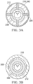
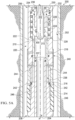
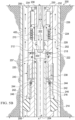
- FIGS. 3A and 3B are schematic lateral cross-sectional views of the example stage cementing well tool 200 along cut sections 3A-3A and 3B-3B, respectively, of FIG. 2 .
- the inner mandrel 212 includes a piston head 304 on a downhole end of the inner mandrel 212 that interfaces with the fluid in the isolated chamber 238.
- FIGS. 3A and 3B represent the inner mandrel 212 in the first, closed position.
- the fluid in the isolated chamber 238 is pressurized to apply a longitudinal force on an uphole end of the setting sleeve 216 to move the setting sleeve 216.
- the fluid travels through slots 306 in the tubular housing 210 to reach the uphole end of the setting sleeve 216.
- the example well tool 200 of FIGS. 2 to 4 shows a hydraulic system (e.g., isolated chamber 238) to actuate the setting sleeve 216.
- actuation of the setting sleeve 216 can be different, such as from direct contact of the inner mandrel 212.
- a surface of the inner mandrel 212 can (directly or indirectly) contact a surface of the setting sleeve 216 such that the setting sleeve 216 mechanically moves with the inner mandrel 212 due to direct or indirect contact between the inner mandrel 212 and the setting sleeve 216.
- the setting sleeve 216 includes a tubular extension 240 that extends upwardly (e.g., in a longitudinally uphole direction) along an outer surface of the tubular housing 210.
- the tubular extension 240 covers an outlet end of the housing port 218. Movement of the setting sleeve 216 to the second, expanded position moves the tubular extension 240 downwardly (e.g., in a longitudinally downhole direction) so the outlet end of the housing port 218 is uncovered.
- the well tool includes a locking mechanism to lock the setting sleeve 216 in the second, extended position.
- a spring loaded lock 242 disposed in the tubular housing 210 mates with a recess 244 in the setting sleeve 216 to lock the setting sleeve 216 in the second, extended position.
- the packer element 214 of the example well tool 200 is shown as a mechanical packer (e.g., steel wire reinforced elastomer packer), where the mechanical packer is longitudinally compressed by the setting sleeve 216, resulting in lateral extension of the mechanical packer element 214 to seal against walls of the wellbore 202.
- the mechanical packer element 214 is extruded, such that it compresses in a longitudinal direction and extends in a lateral direction.
- the packer element 214 can include another type of packer, such as an inflatable packer, swellable packer, or other.
- the well tool 200 includes a grip surface 246, such as a rough surface, anti-slip surface, or other surface, to grip and at least partially hold the setting sleeve 216 in the second, expanded position.
- the example well tool 200 of FIGS. 2-4 does not include (e.g., is free from) a plug seat along its longitudinal length.
- a plug seat is not needed to actuate movement of the inner mandrel 212 and/or set the packer element 214.
- the well tool 200 is part of a work string disposed in the wellbore 202, where the work string can include a plug, ball, or other type of seal that pressure seals the central bore 204 at a location of the work string that is downhole of the well tool 200.
- the example well tool 200 can rely on the downhole seal of the well string to hydraulically actuate the inner mandrel 212, without needing its own dedicated hydraulic seal within the well tool 200 to selectively open and close the flow ports.
- the well tool 200 can utilize existing downhole pressure seals in the central bore to hydraulically actuate the inner mandrel 212 of the example well tool 200, for example, to perform stage cementing operations.
- a diameter of the central bore 204 of the well tool 200 is not obstructed, reduced, or otherwise limited along the longitudinal length of the well tool 200 between its uphole end 206 and downhole end 208.
- the diameter of the central bore 204 at the uphole end 206 is at least sustained along the length of the well tool 200.
- the diameter of the central bore 204 varies along the longitudinal length of the well tool 200, but does not decrease at any point along the well tool 200 to a diameter less than the diameter at the uphole end 206.
- the well tool 200 includes a tool locking profile 300 defined in an inner surface of the inner mandrel 212 that faces the central bore 204.
- the tool locking profile 300 is configured to engage an operating tool, for example, to mechanically overcome the spring force of the spring 224 and move the inner mandrel 212 to the second, open position.
- FIGS. 5A and 5B are schematic partial cross-sectional views of the example stage cementing well tool 200 with the tool locking profile 300 engaged with an example operating tool 302.
- the operating tool 302 includes a tool profile that corresponds with the tool locking profile 300 of the inner mandrel 212. In FIGS.
- the example operating tool 302 includes a ring-shaped radial protrusion that extends into a corresponding ring-shaped recess in the tool locking profile 300 of the inner mandrel 212. This engagement allows a longitudinal force or movement of the operating tool 302 (e.g., slack-off weight of the operating tool 302 acting as a downhole force) to transfer to the inner mandrel 212.
- the tool locking profile 300 and corresponding tool profile can be different than the example tool profile and tool locking profile 300 shown.
- the profiles can include interlocking teeth and slots, non-radial protrusions and non-radial recesses, and/or other complementing profile shapes that allow transfer of longitudinal movement (e.g., along longitudinal axis A-A) from the operating tool to the inner mandrel.
- the tool profile of the operating tool 302 is selectively controlled to engage and disengage the inner mandrel 212, for example, by radially retracting or extending a protrusion of the tool profile into a recess of the tool locking profile 300.
- FIGS. 5A and 5B show the tool profile of the operating tool 302 engaged with the tool locking profile 300 of the inner mandrel 212, where FIG. 5A depicts the inner mandrel 212 in the first, closed position and FIG. 5B depicts the inner mandrel 212 in the second, open position.
- the example well tool 200 of FIGS. 2 through 5B may be used in a stage cementing operation in a well.
- a well operator can pressure-up the central bore of the work string to a desired pressure.
- the inner mandrel 212 moves from the first, closed position (see FIG. 2 ) to the second, open position (see FIG. 4 ). Movement of the inner mandrel 212 to the second, open position moves the setting sleeve 216 from the first, retracted position (see FIG.
- the setting sleeve 216 sets the packer element 214 to seal with walls of the wellbore 202, or an outer casing, thereby sealing the annulus 220 at the location of the packer element 214.
- the packer element 214 and the setting sleeve 216 can be locked in place, for example, by the locking mechanism (e.g., spring-loaded lock 242).
- the packer element 214 can be pressure tested after it is set in the annulus 220.
- the housing port 218 and the passage 222 in the inner mandrel are aligned to allow cement, concrete slurry, or other fluid to pass from the central bore 204 (or from operating tool 302) through the aligned housing port 218 and passage 222 and into the annulus 220 to fill the annulus 220.
- pressure in the central bore 204 is maintained above the threshold hydraulic pressure while cement is pumped down the central bore of the work string to the central bore 204 of the well tool 200.
- the path of the cement, concrete slurry, or other fluid is depicted in FIGS. 4 and 5B with arrows 400.
- a pressure in the central bore 204 of the well tool 200 can be decreased (e.g., bleed-off pressure) to a pressure less than the threshold fluid pressure, and the inner mandrel 212 returns to the first, closed position, for example, due to the spring force of the biasing spring 224 or movement of the operating tool 302.
- FIG. 6 shows the example well tool 200 at this stage during the stage cementing operation, where the inner mandrel 212 has returned to the first, closed position, the setting sleeve 216 remains in the second, expanded position, and the cement, concrete slurry, or other fluid has filled the annulus 220 substantially about the well tool 200 and above the packer element 214.
- FIG. 7A and 7B are schematic lateral cross-sectional views of the example stage cementing well tool 200 along cut sections 7A-7A and 7B-7B, respectively, of FIG. 6 .
- FIG. 7A is a lateral cross-sectional view at the location of the housing ports 218, showing the housing ports 218 plugged by the walls of the inner mandrel 212 in the second, closed position.
- FIG. 7B is a lateral cross-sectional view at the location of the isolated fluid chamber 238, showing the isolated fluid chamber 238 with the inner mandrel 212 in the first, closed position, the setting sleeve 216 in the second, expanded position, and the tubular extension 240 of the setting sleeve 216 maintaining an outer wall of the isolated fluid chamber 238.
Landscapes
- Life Sciences & Earth Sciences (AREA)
- Engineering & Computer Science (AREA)
- Geology (AREA)
- Mining & Mineral Resources (AREA)
- Physics & Mathematics (AREA)
- Environmental & Geological Engineering (AREA)
- Fluid Mechanics (AREA)
- General Life Sciences & Earth Sciences (AREA)
- Geochemistry & Mineralogy (AREA)
- Consolidation Of Soil By Introduction Of Solidifying Substances Into Soil (AREA)
- Pipe Accessories (AREA)
Claims (15)
- Bohrlochwerkzeug zur Verwendung beim Fertigstellen eines Bohrlochs, wobei das Bohrlochwerkzeug Folgendes umfasst:ein rohrförmiges Gehäuse (210), das eine zentrale Bohrung (204) und einen Gehäuseanschluss (218) durch eine Wand des rohrförmigen Gehäuses aufweist, wobei das rohrförmige Gehäuse eine Fluiddruckkammer (232) enthält, die mit der zentralen Bohrung durch einen Fluideinlassanschluss (230) fluidtechnisch gekoppelt ist, und die zentrale Bohrung auf einer longitudinalen Länge des Bohrlochwerkzeugs keinerlei Stopfensitz aufweist;einen inneren Dorn (212), der in dem rohrförmigen Gehäuse angeordnet ist und zwischen einer ersten, geschlossenen Position und einer zweiten, offenen Position wahlweise und in Reaktion auf einen Fluiddruck in der zentralen Bohrung und in der Fluiddruckkammer (232) beweglich ist, wobei der innere Dorn (212) ausgelegt ist, den Gehäuseanschluss zu öffnen, wenn der innere Dorn in der zweiten, offenen Position ist, wobei eine Oberfläche des inneren Dorns mit einem Fluid in einem Innenraum der Fluiddruckkammer in Kontakt ist, wobei der innere Dorn ausgelegt ist, sich in Reaktion auf den Hydraulikdruck des Fluids in der Fluiddruckkammer, der auf die Oberfläche des inneren Dorns wirkt, die mit dem Fluid in den Innenraum der Fluiddruckkammer in Kontakt ist, zu bewegen;ein Dichtungselement (214), das einen Abschnitt des rohrförmigen Gehäuses umschreibt; undeine Einstellhülse (216), die zwischen einer ersten, eingefahrenen Position und einer zweiten, ausgefahrenen Position beweglich ist, wobei die Einstellhülse ausgelegt ist, das Dichtungselement in der zweiten, ausgefahrenen Position in Reaktion auf eine Bewegung des inneren Dorns in die zweite, offene Position zu aktivieren.
- Bohrlochwerkzeug nach Anspruch 1, das ferner ein Vorbelastungselement (224) zwischen dem inneren Dorn und dem rohrförmigen Gehäuse umfasst, um den inneren Dorn in die erste, geschlossene Position vorzubelasten.
- Bohrlochwerkzeug nach Anspruch 1, wobei der innere Dorn einen Durchlass (222) durch eine Wand des inneren Dorns umfasst, wobei der Durchlass auf den Gehäuseanschluss ausgerichtet werden kann, wenn der innere Dorn in der zweiten, offenen Position ist.
- Bohrlochwerkzeug nach Anspruch 1, das ferner einen Filter (236) umfasst, der in dem Fluideinlassanschluss angeordnet ist.
- Bohrlochwerkzeug nach Anspruch 1, wobei der innere Dorn ein Werkzeugverriegelungsprofil (300) umfasst, das in einer inneren Oberfläche des inneren Dorns definiert ist, die der zentralen Bohrung zugewandt ist, wobei das Werkzeugverriegelungsprofil ausgelegt ist, mit einem Arbeitswerkzeug in Eingriff zu gelangen.
- Bohrlochwerkzeug nach Anspruch 1, wobei die zentrale Bohrung (204) des Bohrlochwerkzeugs einen Vollbohrungsdurchgang umfasst, der einen Durchmesser besitzt, der auf der gesamten longitudinalen Länge des Bohrlochwerkzeugs nicht eingeschnürt, reduziert oder auf andere Weise begrenzt ist.
- Bohrlochwerkzeug nach Anspruch 1, wobei sich ein Durchmesser der zentralen Bohrung (204) entlang der longitudinalen Länge des Bohrlochwerkzeugs (200) ändert, jedoch an keinem Punkt entlang des Bohrlochwerkzeugs (200) auf einen Durchmesser abnimmt, der kleiner als ein Durchmesser an einem oberen Ende (206) des Bohrlochwerkzeugs (200) ist.
- Bohrlochwerkzeug nach Anspruch 1, das ferner einen Verriegelungsmechanismus (242) umfasst, der zwischen dem rohrförmigen Gehäuse und der Einstellhülse angeordnet ist, wobei der Verriegelungsmechanismus ausgelegt ist, die Einstellhülse in der zweiten, ausgefahrenen Position zu verriegeln.
- Bohrlochwerkzeug nach Anspruch 1, das ferner ein Fluid in einer isolierten Fluidkammer (238), die in dem rohrförmigen Gehäuse angeordnet ist, enthält, wobei das Fluid mit einer Oberfläche des inneren Dorns um ein erstes Ende der isolierten Fluidkammer und mit einer Oberfläche der Einstellhülse um ein zweites Ende der isolierten Fluidkammer in Kontakt ist und eine Bewegung des inneren Dorns in die zweite, offene Position das Fluid mit Druck beaufschlagt, um die Einstellhülse in die zweite, ausgefahrenen Position zu bewegen.
- Bohrlochwerkzeug nach Anspruch 1, wobei das Dichtungselement beispielsweise ein Packer-Element (214) umfasst, wobei das Packer-Element einen mechanischen Packer und/oder einen schwellfähigen Packer und/oder einen aufblasbaren Packer umfasst.
- Bohrlochwerkzeug nach Anspruch 1, wobei:das Bohrlochwerkzeug ein Bohrlochwerkzeug zur Stufenzementierung ist;der innere Dorn einen Durchlass (222) durch eine Wand des inneren Dorns aufweist, wobei der Durchlass auf den Gehäuseanschluss ausgerichtet werden kann, wenn sich der innere Dorn in der zweiten, offenen Position befindet;das Bohrlochwerkzeug zur Stufenzementierung ein Vorbelastungselement (224) zwischen dem inneren Dorn und dem rohrförmigen Gehäuse umfasst, um den inneren Dorn in einer ersten Richtung in die erste, geschlossene Position vorzubelasten;die Fluiddruckkammer durch eine Oberfläche des rohrförmigen Gehäuses und eine Oberfläche des inneren Dorns definiert ist; unddas Fluid in einem Innenraum der Fluiddruckkammer eine Hydraulikkraft auf die Oberfläche des inneren Dorns in einer zweiten, entgegengesetzten Richtung in die zweite, offene Position ausüben soll.
- Verfahren, das Folgendes umfasst:Empfangen bei einem Bohrlochwerkzeug nach einem der Ansprüche 1 bis 10 eines Fluiddrucks, der höher als ein Schwellen-Fluiddruck ist, von der zentralen Bohrung des Bohrlochwerkzeugs auf den inneren Dorn des Bohrlochwerkzeugs;Bewegen in Reaktion auf das Empfangen des Fluiddrucks, der höher als der Schwellen-Fluiddruck ist, des inneren Dorns aus der ersten geschlossenen Position in eine zweite, offene Position;Öffnen mit dem inneren Dorn in der zweiten, offenen Position des Gehäuseanschlusses durch die Wand des rohrförmigen Gehäuses, um die zentrale Bohrung und die äußere Umgebung des Bohrlochwerkzeugs fluidtechnisch zu koppeln; undBewegen in Reaktion auf die Bewegung des inneren Dorns aus der ersten, geschlossenen Position in die zweite, offene Position der Einstellhülse aus der ersten, eingefahrenen Position in die zweite, ausgefahrene Position, um das Dichtungselement zu aktivieren.
- Verfahren nach Anspruch 12, das ferner Folgendes umfasst:Empfangen eines Fluiddrucks, der niedriger als der Schwellen-Fluiddruck ist, von der zentralen Bohrung des Bohrlochwerkzeugs; undZurückführen des inneren Dorns in die erste, geschlossene Position, wobei das Zurückführen des inneren Dorns in die erste, geschlossene Position optional das Vorbelasten des inneren Dorns in die erste, geschlossene Position mittels einer Vorbelastungsfeder umfasst, wobei eine Federkraft der Vorbelastungsfeder, die auf den inneren Dorn wirkt, im Wesentlichen gleich dem Schwellen-Fluiddruck ist.
- Verfahren nach Anspruch 12, das ferner das Verriegeln der Einstellhülse in der zweiten, ausgefahrenen Position umfasst.
- Verfahren Anspruch 12, das Folgendes umfasst:Halten eines Fluiddrucks in der zentralen Bohrung über dem Schwellen-Fluiddruck; undPumpen von Zement von innerhalb der zentralen Bohrung durch den Gehäuseanschluss aus dem Bohrlochwerkzeug.
Applications Claiming Priority (2)
| Application Number | Priority Date | Filing Date | Title |
|---|---|---|---|
| US14/952,721 US9945206B2 (en) | 2015-11-25 | 2015-11-25 | Stage cementing tool and method |
| PCT/US2016/029796 WO2017091246A1 (en) | 2015-11-25 | 2016-04-28 | Stage cementing tool and method |
Publications (2)
| Publication Number | Publication Date |
|---|---|
| EP3380699A1 EP3380699A1 (de) | 2018-10-03 |
| EP3380699B1 true EP3380699B1 (de) | 2023-11-29 |
Family
ID=56015096
Family Applications (1)
| Application Number | Title | Priority Date | Filing Date |
|---|---|---|---|
| EP16723580.3A Active EP3380699B1 (de) | 2015-11-25 | 2016-04-28 | Werkzeug und verfahren für stufenweise zementierung |
Country Status (5)
| Country | Link |
|---|---|
| US (1) | US9945206B2 (de) |
| EP (1) | EP3380699B1 (de) |
| CA (1) | CA3006283C (de) |
| SA (1) | SA518391651B1 (de) |
| WO (1) | WO2017091246A1 (de) |
Families Citing this family (19)
| Publication number | Priority date | Publication date | Assignee | Title |
|---|---|---|---|---|
| US10584558B2 (en) * | 2015-06-24 | 2020-03-10 | Thru Tubing Solutions, Inc. | Downhole packer tool |
| EP3517728A1 (de) * | 2018-01-25 | 2019-07-31 | Welltec Oilfield Solutions AG | Kabelgeführtes eingriffswerkzeug für ein bohrloch |
| WO2019218073A1 (en) * | 2018-05-16 | 2019-11-21 | 1966109 Alberta Ltd. | Well string staging tool |
| WO2020040656A1 (en) | 2018-08-24 | 2020-02-27 | Schlumberger Canada Limited | Systems and methods for horizontal well completions |
| CA3053711C (en) * | 2018-08-30 | 2024-01-02 | Avalon Research Ltd. | Plug for a coiled tubing string |
| WO2020236141A1 (en) * | 2019-05-17 | 2020-11-26 | Halliburton Energy Services, Inc. | Wellbore isolation device |
| US11391117B2 (en) | 2019-07-08 | 2022-07-19 | Halliburton Energy Services, Inc. | Annular casing packer collar stage tool for cementing operations |
| WO2021097017A1 (en) | 2019-11-12 | 2021-05-20 | Schlumberger Technology Corporation | Stage cementing collar with cup tool |
| US11125048B1 (en) * | 2020-05-29 | 2021-09-21 | Weatherford Technology Holdings, Llc | Stage cementing system |
| US11566489B2 (en) | 2021-04-29 | 2023-01-31 | Halliburton Energy Services, Inc. | Stage cementer packer |
| US11519242B2 (en) * | 2021-04-30 | 2022-12-06 | Halliburton Energy Services, Inc. | Telescopic stage cementer packer |
| US11898416B2 (en) | 2021-05-14 | 2024-02-13 | Halliburton Energy Services, Inc. | Shearable drive pin assembly |
| US11946337B2 (en) * | 2021-11-16 | 2024-04-02 | Saudi Arabian Oil Company | Lock tool for a subsurface safety valve |
| US11965397B2 (en) | 2022-07-20 | 2024-04-23 | Halliburton Energy Services, Inc. | Operating sleeve |
| US11873696B1 (en) | 2022-07-21 | 2024-01-16 | Halliburton Energy Services, Inc. | Stage cementing tool |
| US11873698B1 (en) | 2022-09-30 | 2024-01-16 | Halliburton Energy Services, Inc. | Pump-out plug for multi-stage cementer |
| CA3264960A1 (en) * | 2023-05-27 | 2024-12-05 | Basin Energy Solutions IP Holdings Corporation | METHOD AND TOOL FOR DIRECTING AN ANNULAR FLOW THROUGH A BOREHOLE INTERVAL |
| US12241331B1 (en) * | 2023-08-29 | 2025-03-04 | Halliburton Energy Services, Inc. | Tight tolerance packer |
| US12241330B1 (en) * | 2023-08-29 | 2025-03-04 | Halliburton Energy Services, Inc. | Tight tolerance packer |
Citations (1)
| Publication number | Priority date | Publication date | Assignee | Title |
|---|---|---|---|---|
| WO2015001451A2 (en) * | 2013-07-04 | 2015-01-08 | BYWORTH, Ian | Packer apparatuses |
Family Cites Families (13)
| Publication number | Priority date | Publication date | Assignee | Title |
|---|---|---|---|---|
| US5279370A (en) | 1992-08-21 | 1994-01-18 | Halliburton Company | Mechanical cementing packer collar |
| US5443124A (en) | 1994-04-11 | 1995-08-22 | Ctc International | Hydraulic port collar |
| US5711372A (en) | 1996-05-21 | 1998-01-27 | Tam International | Inflatable packer with port collar valving and method of setting |
| US6164378A (en) | 1998-01-20 | 2000-12-26 | Baker Hughes Incorporated | Pressure-compensation system |
| GB9916513D0 (en) | 1999-07-15 | 1999-09-15 | Churchill Andrew P | Bypass tool |
| AU2001256872A1 (en) | 2000-04-26 | 2001-11-07 | Triangle Equipment As | Packer, setting tool for a packer and method for setting a packer |
| US6695067B2 (en) * | 2001-01-16 | 2004-02-24 | Schlumberger Technology Corporation | Wellbore isolation technique |
| US6651743B2 (en) | 2001-05-24 | 2003-11-25 | Halliburton Energy Services, Inc. | Slim hole stage cementer and method |
| US7857052B2 (en) | 2006-05-12 | 2010-12-28 | Weatherford/Lamb, Inc. | Stage cementing methods used in casing while drilling |
| US8800655B1 (en) | 2010-02-01 | 2014-08-12 | Michael E. Bailey | Stage cementing tool |
| US8657004B2 (en) * | 2011-03-22 | 2014-02-25 | Saudi Arabian Oil Company | Sliding stage cementing tool |
| US8720561B2 (en) | 2011-04-12 | 2014-05-13 | Saudi Arabian Oil Company | Sliding stage cementing tool and method |
| CA2924452C (en) * | 2013-09-18 | 2019-10-29 | Packers Plus Energy Services Inc. | Hydraulically actuated tool with pressure isolator |
-
2015
- 2015-11-25 US US14/952,721 patent/US9945206B2/en active Active
-
2016
- 2016-04-28 WO PCT/US2016/029796 patent/WO2017091246A1/en not_active Ceased
- 2016-04-28 EP EP16723580.3A patent/EP3380699B1/de active Active
- 2016-04-28 CA CA3006283A patent/CA3006283C/en active Active
-
2018
- 2018-05-23 SA SA518391651A patent/SA518391651B1/ar unknown
Patent Citations (1)
| Publication number | Priority date | Publication date | Assignee | Title |
|---|---|---|---|---|
| WO2015001451A2 (en) * | 2013-07-04 | 2015-01-08 | BYWORTH, Ian | Packer apparatuses |
Also Published As
| Publication number | Publication date |
|---|---|
| EP3380699A1 (de) | 2018-10-03 |
| US20170145784A1 (en) | 2017-05-25 |
| SA518391651B1 (ar) | 2021-07-26 |
| US9945206B2 (en) | 2018-04-17 |
| WO2017091246A1 (en) | 2017-06-01 |
| CA3006283C (en) | 2021-10-12 |
| CA3006283A1 (en) | 2017-06-01 |
Similar Documents
| Publication | Publication Date | Title |
|---|---|---|
| EP3380699B1 (de) | Werkzeug und verfahren für stufenweise zementierung | |
| US11274525B2 (en) | Apparatus for downhole fracking and a method thereof | |
| US8944167B2 (en) | Multi-zone fracturing completion | |
| US8720561B2 (en) | Sliding stage cementing tool and method | |
| EP2689096B1 (de) | Zementierwerkzeug mit schiebebühne | |
| US10487626B2 (en) | Fracturing valve and fracturing tool string | |
| EP1437480B1 (de) | Doppelwerkzeug ohne Elastomer, mit hohem Expandiervermögen | |
| US8931557B2 (en) | Wellbore servicing assemblies and methods of using the same | |
| CA2781721C (en) | Multi-zone fracturing completion | |
| AU2002216209B2 (en) | Method and apparatus for repair operations downhole | |
| AU2002216209A1 (en) | Method and apparatus for repair operations downhole | |
| CA2873541A1 (en) | Fracturing valve and fracturing tool string | |
| US6918440B2 (en) | Testing drill packer | |
| EP4139558B1 (de) | Bohrlochwerkzeugaktuatoren und zugehörige verfahren für öl- und gasanwendungen | |
| CN103781989B (zh) | 多区域压裂完井 |
Legal Events
| Date | Code | Title | Description |
|---|---|---|---|
| STAA | Information on the status of an ep patent application or granted ep patent |
Free format text: STATUS: THE INTERNATIONAL PUBLICATION HAS BEEN MADE |
|
| PUAI | Public reference made under article 153(3) epc to a published international application that has entered the european phase |
Free format text: ORIGINAL CODE: 0009012 |
|
| STAA | Information on the status of an ep patent application or granted ep patent |
Free format text: STATUS: REQUEST FOR EXAMINATION WAS MADE |
|
| 17P | Request for examination filed |
Effective date: 20180601 |
|
| AK | Designated contracting states |
Kind code of ref document: A1 Designated state(s): AL AT BE BG CH CY CZ DE DK EE ES FI FR GB GR HR HU IE IS IT LI LT LU LV MC MK MT NL NO PL PT RO RS SE SI SK SM TR |
|
| AX | Request for extension of the european patent |
Extension state: BA ME |
|
| DAV | Request for validation of the european patent (deleted) | ||
| DAX | Request for extension of the european patent (deleted) | ||
| STAA | Information on the status of an ep patent application or granted ep patent |
Free format text: STATUS: EXAMINATION IS IN PROGRESS |
|
| 17Q | First examination report despatched |
Effective date: 20191127 |
|
| P01 | Opt-out of the competence of the unified patent court (upc) registered |
Effective date: 20230528 |
|
| GRAP | Despatch of communication of intention to grant a patent |
Free format text: ORIGINAL CODE: EPIDOSNIGR1 |
|
| STAA | Information on the status of an ep patent application or granted ep patent |
Free format text: STATUS: GRANT OF PATENT IS INTENDED |
|
| INTG | Intention to grant announced |
Effective date: 20230905 |
|
| GRAS | Grant fee paid |
Free format text: ORIGINAL CODE: EPIDOSNIGR3 |
|
| GRAA | (expected) grant |
Free format text: ORIGINAL CODE: 0009210 |
|
| STAA | Information on the status of an ep patent application or granted ep patent |
Free format text: STATUS: THE PATENT HAS BEEN GRANTED |
|
| AK | Designated contracting states |
Kind code of ref document: B1 Designated state(s): AL AT BE BG CH CY CZ DE DK EE ES FI FR GB GR HR HU IE IS IT LI LT LU LV MC MK MT NL NO PL PT RO RS SE SI SK SM TR |
|
| REG | Reference to a national code |
Ref country code: GB Ref legal event code: FG4D |
|
| REG | Reference to a national code |
Ref country code: CH Ref legal event code: EP |
|
| REG | Reference to a national code |
Ref country code: DE Ref legal event code: R096 Ref document number: 602016084376 Country of ref document: DE |
|
| REG | Reference to a national code |
Ref country code: IE Ref legal event code: FG4D |
|
| REG | Reference to a national code |
Ref country code: NO Ref legal event code: T2 Effective date: 20231129 |
|
| REG | Reference to a national code |
Ref country code: LT Ref legal event code: MG9D |
|
| REG | Reference to a national code |
Ref country code: NL Ref legal event code: MP Effective date: 20231129 |
|
| PG25 | Lapsed in a contracting state [announced via postgrant information from national office to epo] |
Ref country code: GR Free format text: LAPSE BECAUSE OF FAILURE TO SUBMIT A TRANSLATION OF THE DESCRIPTION OR TO PAY THE FEE WITHIN THE PRESCRIBED TIME-LIMIT Effective date: 20240301 |
|
| PG25 | Lapsed in a contracting state [announced via postgrant information from national office to epo] |
Ref country code: IS Free format text: LAPSE BECAUSE OF FAILURE TO SUBMIT A TRANSLATION OF THE DESCRIPTION OR TO PAY THE FEE WITHIN THE PRESCRIBED TIME-LIMIT Effective date: 20240329 |
|
| PG25 | Lapsed in a contracting state [announced via postgrant information from national office to epo] |
Ref country code: LT Free format text: LAPSE BECAUSE OF FAILURE TO SUBMIT A TRANSLATION OF THE DESCRIPTION OR TO PAY THE FEE WITHIN THE PRESCRIBED TIME-LIMIT Effective date: 20231129 |
|
| PG25 | Lapsed in a contracting state [announced via postgrant information from national office to epo] |
Ref country code: ES Free format text: LAPSE BECAUSE OF FAILURE TO SUBMIT A TRANSLATION OF THE DESCRIPTION OR TO PAY THE FEE WITHIN THE PRESCRIBED TIME-LIMIT Effective date: 20231129 |
|
| PG25 | Lapsed in a contracting state [announced via postgrant information from national office to epo] |
Ref country code: LT Free format text: LAPSE BECAUSE OF FAILURE TO SUBMIT A TRANSLATION OF THE DESCRIPTION OR TO PAY THE FEE WITHIN THE PRESCRIBED TIME-LIMIT Effective date: 20231129 Ref country code: IS Free format text: LAPSE BECAUSE OF FAILURE TO SUBMIT A TRANSLATION OF THE DESCRIPTION OR TO PAY THE FEE WITHIN THE PRESCRIBED TIME-LIMIT Effective date: 20240329 Ref country code: GR Free format text: LAPSE BECAUSE OF FAILURE TO SUBMIT A TRANSLATION OF THE DESCRIPTION OR TO PAY THE FEE WITHIN THE PRESCRIBED TIME-LIMIT Effective date: 20240301 Ref country code: ES Free format text: LAPSE BECAUSE OF FAILURE TO SUBMIT A TRANSLATION OF THE DESCRIPTION OR TO PAY THE FEE WITHIN THE PRESCRIBED TIME-LIMIT Effective date: 20231129 Ref country code: BG Free format text: LAPSE BECAUSE OF FAILURE TO SUBMIT A TRANSLATION OF THE DESCRIPTION OR TO PAY THE FEE WITHIN THE PRESCRIBED TIME-LIMIT Effective date: 20240229 |
|
| REG | Reference to a national code |
Ref country code: AT Ref legal event code: MK05 Ref document number: 1636294 Country of ref document: AT Kind code of ref document: T Effective date: 20231129 |
|
| PG25 | Lapsed in a contracting state [announced via postgrant information from national office to epo] |
Ref country code: NL Free format text: LAPSE BECAUSE OF FAILURE TO SUBMIT A TRANSLATION OF THE DESCRIPTION OR TO PAY THE FEE WITHIN THE PRESCRIBED TIME-LIMIT Effective date: 20231129 |
|
| PG25 | Lapsed in a contracting state [announced via postgrant information from national office to epo] |
Ref country code: SE Free format text: LAPSE BECAUSE OF FAILURE TO SUBMIT A TRANSLATION OF THE DESCRIPTION OR TO PAY THE FEE WITHIN THE PRESCRIBED TIME-LIMIT Effective date: 20231129 Ref country code: RS Free format text: LAPSE BECAUSE OF FAILURE TO SUBMIT A TRANSLATION OF THE DESCRIPTION OR TO PAY THE FEE WITHIN THE PRESCRIBED TIME-LIMIT Effective date: 20231129 Ref country code: PL Free format text: LAPSE BECAUSE OF FAILURE TO SUBMIT A TRANSLATION OF THE DESCRIPTION OR TO PAY THE FEE WITHIN THE PRESCRIBED TIME-LIMIT Effective date: 20231129 Ref country code: NL Free format text: LAPSE BECAUSE OF FAILURE TO SUBMIT A TRANSLATION OF THE DESCRIPTION OR TO PAY THE FEE WITHIN THE PRESCRIBED TIME-LIMIT Effective date: 20231129 Ref country code: LV Free format text: LAPSE BECAUSE OF FAILURE TO SUBMIT A TRANSLATION OF THE DESCRIPTION OR TO PAY THE FEE WITHIN THE PRESCRIBED TIME-LIMIT Effective date: 20231129 Ref country code: HR Free format text: LAPSE BECAUSE OF FAILURE TO SUBMIT A TRANSLATION OF THE DESCRIPTION OR TO PAY THE FEE WITHIN THE PRESCRIBED TIME-LIMIT Effective date: 20231129 |
|
| PG25 | Lapsed in a contracting state [announced via postgrant information from national office to epo] |
Ref country code: DK Free format text: LAPSE BECAUSE OF FAILURE TO SUBMIT A TRANSLATION OF THE DESCRIPTION OR TO PAY THE FEE WITHIN THE PRESCRIBED TIME-LIMIT Effective date: 20231129 |
|
| PG25 | Lapsed in a contracting state [announced via postgrant information from national office to epo] |
Ref country code: AT Free format text: LAPSE BECAUSE OF FAILURE TO SUBMIT A TRANSLATION OF THE DESCRIPTION OR TO PAY THE FEE WITHIN THE PRESCRIBED TIME-LIMIT Effective date: 20231129 Ref country code: CZ Free format text: LAPSE BECAUSE OF FAILURE TO SUBMIT A TRANSLATION OF THE DESCRIPTION OR TO PAY THE FEE WITHIN THE PRESCRIBED TIME-LIMIT Effective date: 20231129 |
|
| PG25 | Lapsed in a contracting state [announced via postgrant information from national office to epo] |
Ref country code: SK Free format text: LAPSE BECAUSE OF FAILURE TO SUBMIT A TRANSLATION OF THE DESCRIPTION OR TO PAY THE FEE WITHIN THE PRESCRIBED TIME-LIMIT Effective date: 20231129 |
|
| PG25 | Lapsed in a contracting state [announced via postgrant information from national office to epo] |
Ref country code: SM Free format text: LAPSE BECAUSE OF FAILURE TO SUBMIT A TRANSLATION OF THE DESCRIPTION OR TO PAY THE FEE WITHIN THE PRESCRIBED TIME-LIMIT Effective date: 20231129 Ref country code: SK Free format text: LAPSE BECAUSE OF FAILURE TO SUBMIT A TRANSLATION OF THE DESCRIPTION OR TO PAY THE FEE WITHIN THE PRESCRIBED TIME-LIMIT Effective date: 20231129 Ref country code: RO Free format text: LAPSE BECAUSE OF FAILURE TO SUBMIT A TRANSLATION OF THE DESCRIPTION OR TO PAY THE FEE WITHIN THE PRESCRIBED TIME-LIMIT Effective date: 20231129 Ref country code: IT Free format text: LAPSE BECAUSE OF FAILURE TO SUBMIT A TRANSLATION OF THE DESCRIPTION OR TO PAY THE FEE WITHIN THE PRESCRIBED TIME-LIMIT Effective date: 20231129 Ref country code: EE Free format text: LAPSE BECAUSE OF FAILURE TO SUBMIT A TRANSLATION OF THE DESCRIPTION OR TO PAY THE FEE WITHIN THE PRESCRIBED TIME-LIMIT Effective date: 20231129 Ref country code: DK Free format text: LAPSE BECAUSE OF FAILURE TO SUBMIT A TRANSLATION OF THE DESCRIPTION OR TO PAY THE FEE WITHIN THE PRESCRIBED TIME-LIMIT Effective date: 20231129 Ref country code: CZ Free format text: LAPSE BECAUSE OF FAILURE TO SUBMIT A TRANSLATION OF THE DESCRIPTION OR TO PAY THE FEE WITHIN THE PRESCRIBED TIME-LIMIT Effective date: 20231129 Ref country code: AT Free format text: LAPSE BECAUSE OF FAILURE TO SUBMIT A TRANSLATION OF THE DESCRIPTION OR TO PAY THE FEE WITHIN THE PRESCRIBED TIME-LIMIT Effective date: 20231129 |
|
| PG25 | Lapsed in a contracting state [announced via postgrant information from national office to epo] |
Ref country code: PT Free format text: LAPSE BECAUSE OF FAILURE TO SUBMIT A TRANSLATION OF THE DESCRIPTION OR TO PAY THE FEE WITHIN THE PRESCRIBED TIME-LIMIT Effective date: 20240401 |
|
| PG25 | Lapsed in a contracting state [announced via postgrant information from national office to epo] |
Ref country code: PT Free format text: LAPSE BECAUSE OF FAILURE TO SUBMIT A TRANSLATION OF THE DESCRIPTION OR TO PAY THE FEE WITHIN THE PRESCRIBED TIME-LIMIT Effective date: 20240401 |
|
| REG | Reference to a national code |
Ref country code: DE Ref legal event code: R097 Ref document number: 602016084376 Country of ref document: DE |
|
| PLBE | No opposition filed within time limit |
Free format text: ORIGINAL CODE: 0009261 |
|
| STAA | Information on the status of an ep patent application or granted ep patent |
Free format text: STATUS: NO OPPOSITION FILED WITHIN TIME LIMIT |
|
| PG25 | Lapsed in a contracting state [announced via postgrant information from national office to epo] |
Ref country code: SI Free format text: LAPSE BECAUSE OF FAILURE TO SUBMIT A TRANSLATION OF THE DESCRIPTION OR TO PAY THE FEE WITHIN THE PRESCRIBED TIME-LIMIT Effective date: 20231129 |
|
| PG25 | Lapsed in a contracting state [announced via postgrant information from national office to epo] |
Ref country code: SI Free format text: LAPSE BECAUSE OF FAILURE TO SUBMIT A TRANSLATION OF THE DESCRIPTION OR TO PAY THE FEE WITHIN THE PRESCRIBED TIME-LIMIT Effective date: 20231129 |
|
| REG | Reference to a national code |
Ref country code: DE Ref legal event code: R119 Ref document number: 602016084376 Country of ref document: DE |
|
| 26N | No opposition filed |
Effective date: 20240830 |
|
| PG25 | Lapsed in a contracting state [announced via postgrant information from national office to epo] |
Ref country code: MC Free format text: LAPSE BECAUSE OF FAILURE TO SUBMIT A TRANSLATION OF THE DESCRIPTION OR TO PAY THE FEE WITHIN THE PRESCRIBED TIME-LIMIT Effective date: 20231129 |
|
| PG25 | Lapsed in a contracting state [announced via postgrant information from national office to epo] |
Ref country code: MC Free format text: LAPSE BECAUSE OF FAILURE TO SUBMIT A TRANSLATION OF THE DESCRIPTION OR TO PAY THE FEE WITHIN THE PRESCRIBED TIME-LIMIT Effective date: 20231129 |
|
| REG | Reference to a national code |
Ref country code: CH Ref legal event code: PL |
|
| PG25 | Lapsed in a contracting state [announced via postgrant information from national office to epo] |
Ref country code: LU Free format text: LAPSE BECAUSE OF NON-PAYMENT OF DUE FEES Effective date: 20240428 |
|
| REG | Reference to a national code |
Ref country code: BE Ref legal event code: MM Effective date: 20240430 |
|
| PG25 | Lapsed in a contracting state [announced via postgrant information from national office to epo] |
Ref country code: LU Free format text: LAPSE BECAUSE OF NON-PAYMENT OF DUE FEES Effective date: 20240428 |
|
| PG25 | Lapsed in a contracting state [announced via postgrant information from national office to epo] |
Ref country code: DE Free format text: LAPSE BECAUSE OF NON-PAYMENT OF DUE FEES Effective date: 20241105 |
|
| PG25 | Lapsed in a contracting state [announced via postgrant information from national office to epo] |
Ref country code: BE Free format text: LAPSE BECAUSE OF NON-PAYMENT OF DUE FEES Effective date: 20240430 |
|
| PG25 | Lapsed in a contracting state [announced via postgrant information from national office to epo] |
Ref country code: FR Free format text: LAPSE BECAUSE OF NON-PAYMENT OF DUE FEES Effective date: 20240430 |
|
| PG25 | Lapsed in a contracting state [announced via postgrant information from national office to epo] |
Ref country code: FR Free format text: LAPSE BECAUSE OF NON-PAYMENT OF DUE FEES Effective date: 20240430 Ref country code: DE Free format text: LAPSE BECAUSE OF NON-PAYMENT OF DUE FEES Effective date: 20241105 Ref country code: BE Free format text: LAPSE BECAUSE OF NON-PAYMENT OF DUE FEES Effective date: 20240430 Ref country code: CH Free format text: LAPSE BECAUSE OF NON-PAYMENT OF DUE FEES Effective date: 20240430 |
|
| PG25 | Lapsed in a contracting state [announced via postgrant information from national office to epo] |
Ref country code: IE Free format text: LAPSE BECAUSE OF NON-PAYMENT OF DUE FEES Effective date: 20240428 |
|
| PGFP | Annual fee paid to national office [announced via postgrant information from national office to epo] |
Ref country code: GB Payment date: 20250410 Year of fee payment: 10 |
|
| PGFP | Annual fee paid to national office [announced via postgrant information from national office to epo] |
Ref country code: NO Payment date: 20250409 Year of fee payment: 10 |
|
| PG25 | Lapsed in a contracting state [announced via postgrant information from national office to epo] |
Ref country code: CY Free format text: LAPSE BECAUSE OF FAILURE TO SUBMIT A TRANSLATION OF THE DESCRIPTION OR TO PAY THE FEE WITHIN THE PRESCRIBED TIME-LIMIT; INVALID AB INITIO Effective date: 20160428 |
|
| PG25 | Lapsed in a contracting state [announced via postgrant information from national office to epo] |
Ref country code: HU Free format text: LAPSE BECAUSE OF FAILURE TO SUBMIT A TRANSLATION OF THE DESCRIPTION OR TO PAY THE FEE WITHIN THE PRESCRIBED TIME-LIMIT; INVALID AB INITIO Effective date: 20160428 |
|
| PG25 | Lapsed in a contracting state [announced via postgrant information from national office to epo] |
Ref country code: FI Free format text: LAPSE BECAUSE OF FAILURE TO SUBMIT A TRANSLATION OF THE DESCRIPTION OR TO PAY THE FEE WITHIN THE PRESCRIBED TIME-LIMIT Effective date: 20231129 |