EP3380729B1 - Anschubvorrichtung für schiebetür - Google Patents
Anschubvorrichtung für schiebetür Download PDFInfo
- Publication number
- EP3380729B1 EP3380729B1 EP16818974.4A EP16818974A EP3380729B1 EP 3380729 B1 EP3380729 B1 EP 3380729B1 EP 16818974 A EP16818974 A EP 16818974A EP 3380729 B1 EP3380729 B1 EP 3380729B1
- Authority
- EP
- European Patent Office
- Prior art keywords
- housing
- sliding door
- furniture
- pushing
- bowden cable
- Prior art date
- Legal status (The legal status is an assumption and is not a legal conclusion. Google has not performed a legal analysis and makes no representation as to the accuracy of the status listed.)
- Not-in-force
Links
Images


Classifications
-
- F—MECHANICAL ENGINEERING; LIGHTING; HEATING; WEAPONS; BLASTING
- F03—MACHINES OR ENGINES FOR LIQUIDS; WIND, SPRING, OR WEIGHT MOTORS; PRODUCING MECHANICAL POWER OR A REACTIVE PROPULSIVE THRUST, NOT OTHERWISE PROVIDED FOR
- F03G—SPRING, WEIGHT, INERTIA OR LIKE MOTORS; MECHANICAL-POWER PRODUCING DEVICES OR MECHANISMS, NOT OTHERWISE PROVIDED FOR OR USING ENERGY SOURCES NOT OTHERWISE PROVIDED FOR
- F03G7/00—Mechanical-power-producing mechanisms, not otherwise provided for or using energy sources not otherwise provided for
- F03G7/06—Mechanical-power-producing mechanisms, not otherwise provided for or using energy sources not otherwise provided for using expansion or contraction of bodies due to heating, cooling, moistening, drying or the like
- F03G7/061—Mechanical-power-producing mechanisms, not otherwise provided for or using energy sources not otherwise provided for using expansion or contraction of bodies due to heating, cooling, moistening, drying or the like characterised by the actuating element
- F03G7/0614—Mechanical-power-producing mechanisms, not otherwise provided for or using energy sources not otherwise provided for using expansion or contraction of bodies due to heating, cooling, moistening, drying or the like characterised by the actuating element using shape memory elements
- F03G7/06143—Wires
-
- E—FIXED CONSTRUCTIONS
- E05—LOCKS; KEYS; WINDOW OR DOOR FITTINGS; SAFES
- E05F—DEVICES FOR MOVING WINGS INTO OPEN OR CLOSED POSITION; CHECKS FOR WINGS; WING FITTINGS NOT OTHERWISE PROVIDED FOR, CONCERNED WITH THE FUNCTIONING OF THE WING
- E05F1/00—Closers or openers for wings, not otherwise provided for in this subclass
- E05F1/08—Closers or openers for wings, not otherwise provided for in this subclass spring-actuated, e.g. for horizontally sliding wings
- E05F1/16—Closers or openers for wings, not otherwise provided for in this subclass spring-actuated, e.g. for horizontally sliding wings for sliding wings
-
- E—FIXED CONSTRUCTIONS
- E05—LOCKS; KEYS; WINDOW OR DOOR FITTINGS; SAFES
- E05Y—INDEXING SCHEME ASSOCIATED WITH SUBCLASSES E05D AND E05F, RELATING TO CONSTRUCTION ELEMENTS, ELECTRIC CONTROL, POWER SUPPLY, POWER SIGNAL OR TRANSMISSION, USER INTERFACES, MOUNTING OR COUPLING, DETAILS, ACCESSORIES, AUXILIARY OPERATIONS NOT OTHERWISE PROVIDED FOR, APPLICATION THEREOF
- E05Y2201/00—Constructional elements; Accessories therefor
- E05Y2201/40—Motors; Magnets; Springs; Weights; Accessories therefor
- E05Y2201/47—Springs
- E05Y2201/474—Compression springs
-
- E—FIXED CONSTRUCTIONS
- E05—LOCKS; KEYS; WINDOW OR DOOR FITTINGS; SAFES
- E05Y—INDEXING SCHEME ASSOCIATED WITH SUBCLASSES E05D AND E05F, RELATING TO CONSTRUCTION ELEMENTS, ELECTRIC CONTROL, POWER SUPPLY, POWER SIGNAL OR TRANSMISSION, USER INTERFACES, MOUNTING OR COUPLING, DETAILS, ACCESSORIES, AUXILIARY OPERATIONS NOT OTHERWISE PROVIDED FOR, APPLICATION THEREOF
- E05Y2900/00—Application of doors, windows, wings or fittings thereof
- E05Y2900/20—Application of doors, windows, wings or fittings thereof for furniture, e.g. cabinets
Definitions
- the invention relates to a starting device for pushing a sliding door in a starting direction relative to a furniture body with a housing and with a relative to this movable carrier, wherein the driver is part of a guided in the housing, by a spring against the direction of start loaded piston unit and wherein the spring by means of a Bowden cable forming shape memory element is resilient and a piece of furniture with a furniture body and with at least one sliding relative to the furniture body sliding door as furniture pieces and with a starting device for pushing the sliding door.
- the DE 103 01 798 A1 discloses an actuator with a shape memory element, with the position of an actuator is bistable switchable between two positions. The electrical connections of both ends of the shape memory element are to be guided by a common plug. As in a design with a hose nozzle a short circuit of the non-isolated shape memory element can be avoided, it is not apparent from this document.
- a drive device in which a shape memory element is connected to a plunger-like actuating element.
- a surrounding the shape memory element insulating layer leads to a slow cooling of the after switching off the power source Shape memory element and thus to a long time interval until reconnection.
- the DE 10 2010 021183 A1 shows the features of the preamble of claim 1.
- the present invention has for its object to develop a reliable start-up device for a sliding door.
- the driver on a pointing in the direction of start stop surface.
- the Bowden cable penetrates the piston unit, the spring and the housing.
- the Bowden cable has a piston unit-side end arranged outside the piston unit and a housing-side end arranged relative to this, which is arranged outside the housing and can be connected to two poles of a current source.
- the housing is attached either to the furniture body or to the sliding door.
- the driver can be contacted to the respective other piece of furniture in a portion of the total stroke of the furniture pieces to each other.
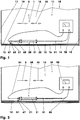
- FIGS. 1, 3 and 5 show a sliding door cabinet (10) with a furniture body (11) and three sliding doors (12 - 14) in a view from below on the ceiling (15).
- a middle sliding door (13) is guided in front of the two outer sliding doors (12, 14). However, this middle sliding door (13) can also be guided behind the outer sliding doors (12, 14).
- the left sliding door (12) and the right outer sliding door (14) are movable on common guideways, for example, so that either the right sliding door (14) or the left sliding door (12) can be opened.
- the starting direction is oriented in the opposite direction.
- the middle sliding door (13) can be opened in both directions.
- FIG. 1 shows the sliding door cabinet (10) with closed sliding doors (12 - 14). In the presentation of the FIG. 3 the left sliding door (12) is partially pushed.
- FIG. 5 shows the cabinet (10) with fully opened left sliding door (12). Both the furniture body (11) and the sliding doors (12-14) are pieces of furniture (11-14).
- the furniture body (11) has two side walls (17, 18) which adjoin the ceiling (15) and form stops for the closed outer sliding doors (12, 14).
- the upper guide rails (16) are arranged on the ceiling (15).
- a driving element (21) is attached on the inside (19) of the left sliding door (12).
- a device (30) for pushing a sliding door (12-14) and a power source (90) are arranged on the ceiling (15) of the cabinet (10).
- the starting device (30) for e.g. All three sliding doors (12-14) may be similar.
- the starting device (30) can also be arranged on the individual sliding door (12-14), wherein the driving element (21) is then arranged on the furniture body (11) as another piece of furniture (11).
- FIGS. 2 and 4 show longitudinal sections of the starting device (30). This shows the FIG. 2 a section of the starting device (30) FIG. 1 and the FIG. 4 a cut in the FIG. 3 illustrated device (30) for pushing a sliding door (12 - 14).
- the starting device (30) has a housing (31) and a piston unit (60) movable relative thereto.
- the housing (31) is fixed, for example, on the ceiling (15) of the furniture body (11) by means of two mounting brackets (32) and an adapter plate, not shown here.
- the housing (31) has a length of 140 millimeters and a diameter of 20 millimeters.
- the housing (31) comprises a cylindrically shaped housing body (33) which bears on the front side a disk-shaped housing cover (34) screwed to the housing body (33), for example.
- the housing cover (34) has a central cover opening (39) which surrounds the piston unit (60).
- the housing bottom (35) has a centrally disposed opening (36).
- the diameter of this, for example, circular breakthrough (36) is 1.2 millimeters in the embodiment.
- On its peripheral surface (37) has the housing body (33) annular grooves (38), in which engage the mounting brackets (32).
- the housing (31) carries at its end facing away from the piston unit (60) a tubular casing (51), which is fixed, for example, with much play on the ceiling (15).
- This hose-like sheath (51) inserted in the embodiment in a housing recess (41) and is loosely on the housing (31).
- the tubular sheath (51) may also be part of the housing (31) or be integrated into this. It has a length of 2 meters and an outer diameter of five millimeters in the embodiment.
- the tubular casing (51) has a longitudinal opening (52) with a constant over its length inner diameter of, for example, 1.5 millimeters. This inner diameter is thus greater by 25% than the diameter of the opening (36) of the housing bottom (35).
- the center lines of the longitudinal opening (52) and the housing bottom opening (36) are aligned with each other.
- the piston unit (60) is guided in the housing (31) and protrudes on one side out of this. It comprises a rod (61) and a driver (67) oriented normal to the starting direction (5) of, for example, the left-hand sliding door (12).
- a driver 67
- the door-side driving element (21) with a stop surface (68), wherein the driving element (21) in the direction of start (5) in front of the driver (67).
- the Indian FIG. 1 shown driver (67) has a single stop surface (68). He is thus formed monovalent.
- the rod (61) has a rod aperture (66) oriented in the longitudinal direction (45) and has a rod portion (62), a piston collar (63) and a guide portion (64).
- the rod portion (62) penetrates the unsealed Housing cover (34) and connects the piston collar (63) with the driver (67).
- the rod portion (62) is guided in the housing cover (34) by means of a clearance fit.
- On the driver side of the rod portion (62) has a retaining pin (65) on which the driver (67) is attached.
- the driver (67) may be glued to the rod portion (62).
- a driver bore (69) penetrating the driver (67) is aligned with the rod aperture (66).
- the piston collar (63) is cylindrical and guided on the housing inner wall (43) of the housing interior (44).
- the guide section (64) is arranged, which points in the direction of the housing bottom (35).
- a spring (70) in the design of a compression spring (70) which is supported on the housing bottom (35) and on the piston collar (63).
- This spring (70) in the exemplary embodiment has a length of 276 millimeters and 55 turns, an outer diameter of 10 millimeters and a wire thickness of 0.8 millimeters.
- the spring force is between 16 Newton and 22 Newton.
- the housing (31), the tubular casing (51) and the piston unit (60) are made in the embodiment of a thermoplastic material, for example polyoxymethylene (POM).
- POM polyoxymethylene
- This is a semi-crystalline, rigid, tough and elastic polymer. It has a density of 1400 kilograms per cubic meter and a tensile elastic modulus of 2800 Newton per square millimeter. Its thermal conductivity is, for example, 0.24 watts per meter and Kelvin. The thermal conductivity is thus greater than 0.2 watts per meter and Kelvin.
- the specific electrical resistance of the material is 10 13 ohms per meter.
- the material can be filled with molybdenum disulfide, for example, to improve the sliding and wear behavior.
- the use of another material or a composite material is conceivable.
- the individual components can be made of different materials.
- this wire (81) From the piston unit (60) and from the hose-like sheath (51) protrude the ends (82, 83) of a wire (81), which penetrates the housing (31), the spring (70) and the piston unit (60). At the ends (82, 83) of this wire (81) are connected electrical leads (84, 85) connecting the wire (81) to the power source (90), e.g. a DC power source (90) connect.
- this power source (90) has a voltage of 24 volts and provides a 5 ampere current.
- the wire (81) carries at its two ends fixing elements (86, 87).
- the fixing element (86) at the piston unit end (82) is formed as a cone clamping sleeve (86), which in the representations of Figures 1 - 5 on the driver (67) is applied.
- the sleeve (86) prevents at least the retraction of the wire end (82) in the piston unit (60).
- the fixation (82) is thus formed monovalent.
- the wire end (82) may also be fixed in the piston unit (60). For example, it can then bivalent also limit the pulling out of the wire (81).
- the wire (81) carries as a fixing element (87), e.g. a fixing clip (87).
- a fixing element e.g. a fixing clip (87).
- the fixing bracket (87) is monovalent to the tubular casing (51) and prevents monovalent retraction of the end (83) of the wire (81) in the tubular casing (51) and in the housing (31).
- the wire end (83) can also be secured divalent relative to the tubular casing (51) or to the housing (31).
- the wire (81) is made of, for example, a nickel-titanium alloy and has a diameter of 0.5 millimeters. Its tensile strength is, for example, between 270 Newton per square millimeter and 400 Newton per square millimeter.
- This wire (81) with a length of for example 2.5 meters forms a wire-shaped shape memory element (81).
- the example pretreated shape memory element (81) has two reversible shapes in the embodiment. By changing the temperature, it is almost switchable between these figures. It allows only a slight elastic deformation. Upon heating, for example after the wire has been subjected to an electrical current flow, a structural transformation begins at a temperature of, for example, 60 degrees.
- the specific current density along the wire (81) is, for example, greater than 10 amperes per square millimeter. In the exemplary embodiment, it is 25.5 amperes per square millimeter.
- This conversion process continues with further heating, for example up to a temperature of 90 degrees Celsius.
- the shape memory element (81) shortens. For example, it takes its in the FIG. 3 shown shortened length, eg 97% of its original length, a. Upon further heating there is no further conversion.
- the shape memory element (81) maintains its shape.
- the shape memory element (81) After switching off the power source (90) cools the shape memory element (81) again. For example, once it has reached a temperature of 60 degrees Celsius, it has taken its original length again.
- the conversion process between the two shapes may have hysteresis. Recovery can also be accomplished solely by discharging a potential energy storage, e.g. a spring, done.
- the wire-shaped shape memory element (81) is guided through the tubular casing (51), the housing (31), the spring (70) and the rod (61). Thereafter, these parts (31, 51, 61, 81) are pushed together and closed the housing cover (34).
- the tubular casing (51) is attached to the housing (31).
- the driver (67) on the wire-shaped shape memory element (81) can be attached.
- the wire (81) can now be straightened at its two ends so that it has no loops, deflections, etc. between its two ends.
- the driver (67) e.g. the cone clamping sleeve (86) pushed onto the wire (81) and fixed thereto. Outside the tubular casing (51), e.g. the fixing clip (87) attached to the wire.
- the conical clamping sleeve (86) and the fixing element (87) can be mounted in such a way that they rest against the respectively adjacent component (67, 51).
- the wire (81) is then taut stretched between these two fixing elements (86, 87).
- mount the wire (81) in a longitudinally displaceable manner relative to the housing (31) and / or to the piston unit (60).
- the starting device (30) In the cabinet (10), for example, on the inside (19) of e.g. left sliding door (12) the driving element (21) attached.
- the starting device (30) On the ceiling (15) the starting device (30) is e.g. with the two mounting brackets (32) attached to the adapter plate. Another mounting bracket may be used to hold the tubular sheath (51) to the ceiling (15).
- the tubular casing (51) When mounting the starting device (30) on the cabinet (10), the tubular casing (51) may be e.g. unattached on the cabinet (10) rest.
- the starting device (30) is thus compact. Their stroke is e.g. 3% of their total length. For example, depending on the material of the shape memory element (81), the stroke of the starting device (30) may be between 2.5% and 4% of the length of the starting device (30).
- the ends (82, 83) of the wire (81) can be electrically connected to the power source (90).
- the current source (90) is also arranged in the cabinet (10), for example.
- the mounted starting device (30) is arranged in the cabinet (10) such that the longitudinal direction (45) of the housing (31) lies horizontally and parallel to the front of the cabinet (10).
- the driver (67) bears against the carrier element (21) or has a distance of up to five millimeters from it.
- the power source (90) is turned on.
- the current flowing through the wire (81) heats it.
- the air surrounding the wire (81) is heated, which flows through the non-sealed openings (36, 52, 66, 69) into the environment (1). Part of the heat is transferred to the tubular casing (51).
- the high thermal conductivity and the large surface of the tubular casing (51) - the surface (53) corresponds to ten times the surface of the guided in the sheath (51) wire (81) - prevents overheating of the wire (81).
- the inner diameter of each of the wire (81) leading apertures (36, 52, 66, 69) is at least twice as large as the outer diameter of the wire (81).
- the shortening shape memory element (81) forms with the two end fixing elements (86, 87) a Bowden cable (80), the piston unit (60), the tubular casing (51) and the housing (31) against the action of the spring (70 ) charged.
- the piston unit (60) is moved relative to the housing (31) in the direction of start (5), wherein the spring (70) is compressed.
- the driver (67) displaces the entrainment element (21) and the e.g. left sliding door (12) in the direction of start (5).
- the Figures 3 and 4 show the starting device (30) with the shortened Bowden cable (80).
- the example left sliding door (12) is partially open. Now the power source (90) can be switched off. However, it is also conceivable to switch off the current source (90) automatically, for example due to the signal of a position measuring system.
- To further open the example left sliding door (12) pushes the operator, for example, manually from in the FIG. 3 shown partially opened position in the in the FIG. 5 illustrated opened position.
- the sliding door (12) including the entrainment element (21) is decoupled from the monovalent driver (67).
- the shape memory element (81) After switching off the power source (90), the shape memory element (81) cools down.
- the heat released from the wire (81) during cooling is released through the apertures (36, 52, 66, 69) and the surface (53) of the tubular casing (51) to the environment (1), so that no accumulation of heat occurs.
- the spring (70) moves the piston unit (60) outwards relative to the housing (31), ie counter to the starting direction (5).
- the cooling time of the shape memory element (81) is less than 6 seconds, for example.
- this may e.g. manually moved to the closed position.
- the opening then takes place as described above.
Landscapes
- Engineering & Computer Science (AREA)
- Chemical & Material Sciences (AREA)
- Combustion & Propulsion (AREA)
- Mechanical Engineering (AREA)
- General Engineering & Computer Science (AREA)
- Power-Operated Mechanisms For Wings (AREA)
- Closing And Opening Devices For Wings, And Checks For Wings (AREA)
Description
- Die Erfindung betrifft eine Anschubvorrichtung zum Anschieben einer Schiebetür in einer Anschubrichtung relativ zu einem Möbelkorpus mit einem Gehäuse und mit einem relativ zu diesem beweglichen Mitnehmer, wobei der Mitnehmer Teil einer im Gehäuse geführten, mittels einer Feder entgegen der Anschubrichtung belasteten Kolbeneinheit ist und wobei die Feder mittels eines einen Bowdenzug bildenden Formgedächtniselements belastbar ist sowie ein Möbelstück mit einem Möbelkorpus und mit mindestens einer relativ zum Möbelkorpus verschiebbaren Schiebetür als Möbelstückteile sowie mit einer Anschubvorrichtung zum Anschieben der Schiebetür.
- Die
DE 103 01 798 A1 offenbart einen Stellantrieb mit einem Formgedächtniselement, mit dem die Position eines Stellglieds zwischen zwei Positionen bistabil umschaltbar ist. Die elektrischen Anschlüsse beider Enden des Formgedächtniselements sind durch einen gemeinsamen Stecker zu führen. Wie bei einer Ausführung mit einer Schlauchtülle ein Kurzschluss des nicht isolierten Formgedächtniselements vermieden werden kann, geht aus dieser Druckschrift nicht hervor. - Aus der
DE 198 02 639 A1 ist eine Antriebsvorrichtung bekannt, bei der ein Formgedächtniselement an ein stößelartiges Betätigungselement angeschlossen ist. Eine das Formgedächtniselement umgebende Isolierschicht führt nach dem Abschalten der Stromquelle zu einem langsamen Abkühlen des Formgedächtniselements und damit zu einem langen Zeitintervall bis zum Wiedereinschalten. - Die
DE 10 2010 021183 A1 zeigt die Merkmale des Oberbegriffs des Anspruchs 1. - Der vorliegenden Erfindung liegt die Aufgabe zugrunde, eine betriebssichere Anschubvorrichtung für eine Schiebetür zu entwickeln.
- Diese Problemstellung wird mit den Merkmalen des Hauptanspruches gelöst. Dazu weist der Mitnehmer eine in die Anschubrichtung zeigende Anschlagfläche auf. Der Bowdenzug durchdringt die Kolbeneinheit, die Feder und das Gehäuse. Außerdem weist der Bowdenzug ein außerhalb der Kolbeneinheit angeordnetes kolbeneinheitsseitiges Ende und ein relativ zu diesem bewegliches, außerhalb des Gehäuses angeordnetes gehäuseseitiges Ende auf, die an zwei Pole einer Stromquelle anschließbar sind.
- Im Möbelstück ist das Gehäuse entweder am Möbelkorpus oder an der Schiebetür befestigt. Der Mitnehmer ist mit dem jeweils anderen Möbelstückteil in einem Teilbereich des Gesamthubs der Möbelstückteile zueinander kontaktierbar.
- Weitere Einzelheiten der Erfindung ergeben sich aus den Unteransprüchen und der nachfolgenden Beschreibung schematisch dargestellter Ausführungsformen.
- Figur 1:
- Schiebetürschrank mit Anschubvorrichtung;
- Figur 2:
- Schnitt der Anschubvorrichtung aus
Figur 1 ; - Figur 3:
- Schiebetürschrank mit teilweise geöffneter Schiebetür;
- Figur 4:
- Schnitt der Anschubvorrichtung aus
Figur 3 ; - Figur 5:
- Schiebetürschrank mit geöffneter Schiebetür.
- Die
Figuren 1, 3 und5 zeigen einen Schiebetürschrank (10) mit einem Möbelkorpus (11) und drei Schiebetüren (12 - 14) in einer Ansicht von unten auf die Decke (15). Eine mittlere Schiebtür (13) ist vor den beiden äußeren Schiebetüren (12, 14) geführt. Diese mittlere Schiebetür (13) kann jedoch auch hinter den äußeren Schiebetüren (12, 14) geführt sein. Die linke Schiebetür (12) und die rechte äußere Schiebetür (14) sind z.B. auf gemeinsamen Führungsbahnen verfahrbar, sodass entweder die rechte Schiebetür (14) oder die linke Schiebetür (12) öffenbar ist. Zum Öffnen der linken Schiebetür (12) wird diese beispielsweise in der nach rechts orientierten Anschubrichtung (5) verschoben. Für die rechte Schiebetür (14) ist die Anschubrichtung in der Gegenrichtung orientiert. Die mittlere Schiebetür (13) kann in beide Richtungen geöffnet werden. Die Masse der einzelnen Tür beträgt beispielsweise 35 Kilogramm. DieFigur 1 zeigt den Schiebetürschrank (10) mit geschlossenen Schiebetüren (12 - 14). In der Darstellung derFigur 3 ist die linke Schiebetür (12) teilweise aufgeschoben. DieFigur 5 zeigt den Schrank (10) mit vollständig geöffneter linker Schiebetür (12). Sowohl der Möbelkorpus (11) als auch die Schiebetüren (12 - 14) sind Möbelstückteile (11 - 14). - Der Möbelkorpus (11) hat zwei Seitenwände (17, 18), die an die Decke (15) angrenzen und Anschläge für die geschlossenen äußeren Schiebetüren (12, 14) bilden. Die oberen Führungsschienen (16) sind an der Decke (15) angeordnet. Beispielsweise an der Innenseite (19) der linken Schiebetür (12) ist ein Mitnahmeelement (21) befestigt. Dies ist Ausführungsbeispiel ein L-förmiger Winkel, der beispielsweise im oberen Bereich der Schiebetür (12) in den Innenraum des Schranks (10) hineinragt.
- An der Decke (15) des Schranks (10) sind eine Vorrichtung (30) zum Anschieben einer Schiebetür (12 - 14) und eine Stromquelle (90) angeordnet. Die Anschubvorrichtung (30) für z.B. alle drei Schiebetüren (12 - 14) kann gleichartig ausgebildet sein. Die Anschubvorrichtung (30) kann auch an der einzelnen Schiebetür (12 - 14) angeordnet sein, wobei das Mitnahmeelement (21) dann am Möbelkorpus (11) als anderem Möbelstückteil (11) angeordnet ist.
- Die
Figuren 2 und 4 zeigen Längsschnitte der Anschubvorrichtung (30). Hierbei zeigt dieFigur 2 einen Schnitt der Anschubvorrichtung (30) ausFigur 1 und dieFigur 4 einen Schnitt der in derFigur 3 dargestellten Vorrichtung (30) zum Anschieben einer Schiebetür (12 - 14). - Die Anschubvorrichtung (30) hat ein Gehäuse (31) und eine relativ zu dieser bewegliche Kolbeneinheit (60). Das Gehäuse (31) ist beispielsweise an der Decke (15) des Möbelkorpus (11) mittels zweier Befestigungsklammern (32) und einer hier nicht dargestellten Adapterplatte befestigt. Im Ausführungsbeispiel hat das Gehäuse (31) eine Länge von 140 Millimetern und einen Durchmesser von 20 Millimetern. Das Gehäuse (31) umfasst einen zylindrisch ausgebildeten Gehäusekörper (33), der stirnseitig einen mit dem Gehäusekörper (33) z.B. verschraubten scheibenförmigen Gehäusedeckel (34) trägt. Der Gehäusedeckel (34) hat einen zentralen Deckeldurchbruch (39) der die Kolbeneinheit (60) umgreift. Der Gehäuseboden (35) hat einen zentral angeordneten Durchbruch (36). Der Durchmesser dieses z.B. kreisförmig ausgebildeten Durchbruchs (36) beträgt im Ausführungsbeispiel 1,2 Millimeter. An seiner Umfangsfläche (37) hat der Gehäusekörper (33) Ringnuten (38), in die die Befestigungsklammern (32) eingreifen.
- Das Gehäuse (31) trägt an seinem der Kolbeneinheit (60) abgewandten Ende eine schlauchartige Hülle (51), die beispielsweise mit viel Spiel an der Decke (15) fixiert ist. Diese schlauchartige Hülle (51) steckt im Ausführungsbeispiel in einer Gehäuseeinsenkung (41) und liegt lose am Gehäuse (31) an. Die schlauchartige Hülle (51) kann jedoch auch Teil des Gehäuses (31) sein oder in dieses integriert sein. Sie hat im Ausführungsbeispiel eine Länge von 2 Metern und einen Außendurchmesser von fünf Millimetern. Die schlauchartige Hülle (51) hat einen Längsdurchbruch (52) mit einem über seine Länge konstanten Innendurchmesser von beispielsweise 1,5 Millimetern. Dieser Innendurchmesser ist damit um 25 % größer als der Durchmesser des Durchbruchs (36) des Gehäusebodens (35). Die Mittellinien des Längsdurchbruchs (52) und des Gehäusebodendurchbruchs (36) fluchten miteinander.
- Die Kolbeneinheit (60) ist im Gehäuse (31) geführt und ragt einseitig aus diesem heraus. Sie umfasst eine Stange (61) sowie einen normal zur Anschubrichtung (5) der z.B. linken Schiebetür (12) orientierten Mitnehmer (67). In der Darstellung der
Figur 1 kontaktiert der Mitnehmer (67) das türseitige Mitnahmeelement (21) mit einer Anschlagfläche (68), wobei das Mitnahmeelement (21) in der Anschubrichtung (5) vor dem Mitnehmer (67) liegt. Der in derFigur 1 dargestellte Mitnehmer (67) hat eine einzige Anschlagfläche (68). Er ist somit einwertig ausgebildet. - Die Stange (61) hat einen in Längsrichtung (45) orientierten Stangendurchbruch (66) und weist einen Stangenabschnitt (62), einen Kolbenbund (63) und einen Führungsabschnitt (64) auf. Der Stangenabschnitt (62) durchdringt den nicht abgedichteten Gehäusedeckel (34) und verbindet den Kolbenbund (63) mit dem Mitnehmer (67). Beispielsweise ist der Stangenabschnitt (62) im Gehäusedeckel (34) mittels einer Spielpassung geführt. Mitnehmerseitig hat der Stangenabschnitt (62) einen Haltezapfen (65), auf den der Mitnehmer (67) aufgesteckt ist. Beispielsweise kann der Mitnehmer (67) mit dem Stangenabschnitt (62) verklebt sein. Eine den Mitnehmer (67) durchdringende Mitnehmerbohrung (69) fluchtet mit dem Stangendurchbruch (66).
- Der Kolbenbund (63) ist zylindrisch ausgebildet und an der Gehäuseinnenwandung (43) des Gehäuseinnenraums (44) geführt. Auf der dem Stangenabschnitt (62) abgewandten Seite des Kolbenbundes (63) ist der Führungsabschnitt (64) angeordnet, der in Richtung des Gehäusebodens (35) zeigt. Auf diesem Führungsabschnitt (35) sitzt eine Feder (70) in der Bauform einer Druckfeder (70), die sich am Gehäuseboden (35) und am Kolbenbund (63) abstützt. Diese Feder (70) hat im Ausführungsbeispiel eine Länge von 276 Millimetern und 55 Windungen, einen Außendurchmesser von 10 Millimetern und eine Drahtstärke von 0,8 Milimetern. Die Federkraft liegt zwischen 16 Newton und 22 Newton. Die Länge des Führungsabschnitts (64) entspricht beispielsweise der minimalen Länge der komprimierten Feder (70), das sind z.B. 20 % der Länge der unbelasteten Feder (70). Die Kompression der Feder (70) ist damit durch das Anstoßen des Führungsabschnitts (64) am Gehäuseboden (35) begrenzt. Bei einer Entlastung der Feder (70) ist ihr maximaler Hub durch das Anschlagen des Kolbenbunds (63) am Gehäusedeckel (34) begrenzt.
- Das Gehäuse (31), die schlauchartige Hülle (51) und die Kolbeneinheit (60) sind im Ausführungsbeispiel aus einem thermoplastischen Kunststoff, z.B. Polyoxymethylen (POM) hergestellt. Dies ist ein teilkristallines, steifes, zähes und elastisches Polymerisat. Es hat eine Dichte von 1400 Kilogramm pro Kubikmeter und einen Zug-Elastizitätsmodul von 2800 Newton pro Quadratmillimeter. Seine Wärmeleitfähigkeit beträgt beispielsweise 0,24 Watt pro Meter und Kelvin. Die Wärmeleitfähigkeit ist damit größer als 0,2 Watt pro Meter und Kelvin. Der spezifische elektrische Widerstand des Werkstoffs beträgt 1013 Ohm mal Meter. Der Werkstoff kann z.B. zur Verbesserung des Gleit- und Verschleißverhaltens mit Molybdändisulfid gefüllt sein. Auch der Einsatz eines anderen Werkstoffs oder eines Verbundwerkstoffes ist denkbar. Die einzelnen Bauteile können aus unterschiedlichen Werkstoffen hergestellt sein.
- Aus der Kolbeneinheit (60) und aus der schlauchartigen Hülle (51) ragen die Enden (82, 83) eines Drahtes (81) heraus, der das Gehäuse (31), die Feder (70) und die Kolbeneinheit (60) durchdringt. An den Enden (82, 83) dieses Drahtes (81) sind elektrische Leitungen (84, 85) angeschlossen, die den Draht (81) mit der Stromquelle (90), z.B. einer Gleichstromquelle (90) verbinden. Diese Stromquelle (90) hat beispielsweise eine Spannung von 24 Volt und liefert einen Strom mit 5 Ampere.
- Der Draht (81) trägt an seinen beiden Enden Fixierelemente (86, 87). Das Fixierelement (86) am kolbeneinheitsseitigen Ende (82) ist eine als Kegelklemmhülse ausgebildete Hülse (86), die in den Darstellungen der
Figuren 1 - 5 am Mitnehmer (67) anliegt. Die Hülse (86) verhindert zumindest das Einziehen des Drahtendes (82) in die Kolbeneinheit (60). Die Fixierung (82) ist damit einwertig ausgebildet. Das Drahtende (82) kann jedoch auch in der Kolbeneinheit (60) fixiert sein. Beispielsweise kann sie dann zweiwertig auch das Herausziehen des Drahtes (81) begrenzen. - An dem der Kolbeneinheit (60) abgewandten Ende (83) trägt der Draht (81) als Fixierelement (87) z.B. eine Fixierklammer (87). Diese beispielsweise zweiteilige Fixierklammer (87) umgreift klemmend den Draht (81), sodass dieser nicht relativ zur Fixierklammer (87) verschiebbar ist. Im Ausführungsbeispiel liegt die Fixierklammer (87) einwertig an der schlauchartigen Hülle (51) an und verhindert einwertig ein Einziehen des Endes (83) des Drahtes (81) in die schlauchartige Hülle (51) und in das Gehäuse (31). Das Drahtende (83) kann jedoch auch zweiwertig relativ zur schlauchartigen Hülle (51) oder zum Gehäuse (31) gesichert sein.
- Der Draht (81) ist beispielsweise aus einer Nickel-TitanLegierung hergestellt und hat einen Durchmesser von 0,5 Millimetern. Seine Zugfestigkeit beträgt beispielsweise zwischen 270 Newton pro Quadratmillimeter und 400 Newton pro Quadratmillimeter. Dieser Draht (81) mit einer Länge von beispielsweise 2,5 Metern bildet ein drahtförmiges Formgedächtniselement (81). Das z.B. vorbehandelte Formgedächtniselement (81) hat im Ausführungsbeispiel zwei reversible Gestalten. Durch Temperaturänderung ist es zwischen diesen Gestalten quasi umschaltbar. Es lässt nur eine geringfügige elastische Verformung zu. Bei einer Erwärmung, z.B. nach der Beaufschlagung des Drahtes mit einem elektrischen Stromfluß, beginnt ab einer Temperatur von z.B. 60 Grad eine Gefügeumwandlung. Die spezifische Stromdichte entlang des Drahtes (81) ist beispielsweise größer als 10 Ampere pro Quadratmillimeter. Im Ausführungsbeispiel beträgt sie 25,5 Ampere pro Quadratmillimeter. Dieser Umwandlungsvorgang setzt sich bei weiterer Erwärmung, beispielsweise bis zu einer Temperatur von 90 Grad Celsius, fort. Bei der Erwärmung verkürzt sich das Formgedächtniselement (81). Beispielsweise nimmt es seine in der
Figur 3 dargestellte verkürzte Länge, z.B. 97 % seiner ursprünglichen Länge, ein. Bei weiterer Erwärmung erfolgt keine weitere Umwandlung. Bei einer Beibehaltung der Temperatur behält das Formgedächtniselement (81) seine Gestalt bei. - Nach dem Abschalten der Stromquelle (90) kühlt das Formgedächtniselement (81) wieder ab. Sobald es beispielsweise wieder eine Temperatur von 60 Grad Celsius erreicht hat, hat es seine ursprüngliche Länge wieder eingenommen. Der Umwandlungsvorgang zwischen den beiden Gestalten kann eine Hysterese aufweisen. Die Rückverformung kann auch allein durch die Entladung eines Speichers potentieller Energie, z.B. einer Feder, erfolgen.
- Beim Zusammenbau der Anschubvorrichtung (30) wird beispielsweise zunächst das drahtförmige Formgedächtniselement (81) durch die schlauchartige Hülle (51), das Gehäuse (31), die Feder (70) und die Stange (61) geführt. Danach werden diese Teile (31, 51, 61, 81) zusammengeschoben und der Gehäusedeckel (34) verschlossen. Gegebenenfalls wird hierbei die schlauchartige Hülle (51) am Gehäuse (31) befestigt. Nach dem Auffädeln des Mitnehmers (67) auf das drahtförmige Formgedächtniselement (81) kann der Mitnehmer (67) an der Stange (61) befestigt werden. Bei entspannter Feder (70) kann nun der Draht (81) an seinen beiden Enden geradegezogen werden, sodass er zwischen seinen beiden Enden keine Schlaufen, Umlenkungen, etc. aufweist. Auf der Seite des Mitnehmers (67) wird z.B. die Kegelklemmhülse (86) auf den Draht (81) aufgeschoben und an diesem fixiert. Außerhalb der schlauchartigen Hülle (51) wird z.B. die Fixierklammer (87) am Draht befestigt.
- Die Kegelklemmhülse (86) und das Fixierelement (87) können derart montiert sein, dass sie an dem jeweils benachbarten Bauteil (67, 51) anliegen. Der Draht (81) ist dann straff zwischen diesen beiden Fixierelementen (86, 87) gespannt. Es ist aber auch denkbar, den Draht (81) längsverschieblich relativ zum Gehäuse (31) und/oder zur Kolbeneinheit (60) zu montieren. Beispielsweise kann der Draht (81) im Ausführungsbeispiel nach der Montage der Fixierelemente (86, 87) bis zu einem halben Millimeter Spiel in axialer Richtung aufweisen. Auch eine andere Reihenfolge des Zusammenbaus ist denkbar.
- Im Schrank (10) wird beispielsweise an der Innenseite (19) der z.B. linken Schiebetür (12) das Mitnahmeelement (21) befestigt. An der Decke (15) wird die Anschubvorrichtung (30) z.B. mit den zwei Befestigungsklammern (32) an der Adapterplatte befestigt. Eine weitere Befestigungsklammer kann zum Halten der schlauchartigen Hülle (51) an der Decke (15) eingesetzt werden. Bei einer Montage der Anschubvorrichtung (30) auf dem Schrank (10) kann die schlauchartige Hülle (51) z.B. unbefestigt auf dem Schrank (10) aufliegen. Die Anschubvorrichtung (30) ist somit kompakt aufgebaut. Ihr Hub beträgt z.B. 3 % ihrer Gesamtlänge. Beispielsweise kann der Hub der Anschubvorrichtung (30) je nach dem Werkstoff des Formgedächtniselements (81) zwischen 2,5 % und 4 % der Länge der Anschubvorrichtung (30) betragen.
- Nach der Montage der Anschubvorrichtung (30) im Schrank (10) können die Enden (82, 83) des Drahtes (81) elektrisch mit der Stromquelle (90) verbunden werden. Die Stromquelle (90) ist beispielsweise ebenfalls im Schrank (10) angeordnet.
- Die montierte Anschubvorrichtung (30) ist derart im Schrank (10) angeordnet, dass die Längsrichtung (45) des Gehäuses (31) waagerecht und parallel zur Vorderseite des Schranks (10) liegt. Bei geschlossener z.B. linker Schiebetür (12) liegt der Mitnehmer (67) am Mitnahmeelement (21) an oder hat einen Abstand von bis zu fünf Millimetern von diesem. Um beispielsweise die linke äußere Schiebetür (12) zu öffnen, wird die Stromquelle (90) eingeschaltet. Der durch den Draht (81) fließende Strom erwärmt diesen. Hierbei wird auch die den Draht (81) umgebende Luft erwärmt, die durch die nicht abgedichteten Durchbrüche (36, 52, 66, 69) in die Umgebung (1) strömt. Ein Teil der Wärme wird an die schlauchartige Hülle (51) übertragen. Die hohe Wärmeleitfähigkeit und die große Oberfläche der schlauchartigen Hülle (51) - die Oberfläche (53) entspricht dem Zehnfachen der Oberfläche des in der Hülle (51) geführten Drahtes (81) - verhindert eine Überhitzung des Drahtes (81). Außerdem ist der Innendurchmesser eines jeden der den Draht (81) führenden Durchbrüche (36, 52, 66, 69) mindestens doppelt so groß wie der Außendurchmesser des Drahts (81).
- Das sich verkürzende Formgedächtniselement (81) bildet mit den beiden endseitigen Fixierelementen (86, 87) einen Bowdenzug (80), der die Kolbeneinheit (60), die schlauchartige Hülle (51) und das Gehäuse (31) entgegen der Wirkung der Feder (70) belastet. Die Kolbeneinheit (60) wird relativ zum Gehäuse (31) in die Anschubrichtung (5) verschoben, wobei die Feder (70) komprimiert wird. Der Mitnehmer (67) verschiebt das Mitnahmeelement (21) und die z.B. linke Schiebetür (12) in die Anschubrichtung (5).
- Die
Figuren 3 und4 zeigen die Anschubvorrichtung (30) mit dem verkürzten Bowdenzug (80). Die z.B. linke Schiebetür (12) ist teilweise geöffnet. Nun kann die Stromquelle (90) abgeschaltet werden. Es ist aber auch denkbar, die Stromquelle (90) automatisch, z.B. aufgrund des Signals eines Wegmesssystems, abzuschalten. Zum weiteren Öffnen der z.B. linken Schiebetür (12) schiebt der Bediener diese beispielsweise manuell von der in derFigur 3 dargestellten teilgeöffneten Position in die in derFigur 5 dargestellte geöffnete Position. Die Schiebetür (12) einschließlich des Mitnahmeelements (21) ist dabei von dem einwertig ausgebildeten Mitnehmer (67) entkoppelt. - Nach dem Abschalten der Stromquelle (90) kühlt das Formgedächtniselement (81) ab. Der Bowdenzug (80) längt sich. Die beim Abkühlen vom Draht (81) abgegebene Wärme wird durch die Durchbrüche (36, 52, 66, 69) und die Oberfläche (53) der schlauchartigen Hülle (51) an die Umgebung (1) abgegeben, sodass kein Wärmestau entsteht. Die Feder (70) verschiebt die Kolbeneinheit (60) relativ zum Gehäuse (31) nach außen, also entgegen der Anschubrichtung (5). Die Abkühlzeit des Formgedächtniselements (81) ist beispielsweise geringer als 6 Sekunden.
- Zum Schließen der Schiebetür (12) kann diese z.B. manuell in die geschlossene Position verschoben werden. Das Öffnen erfolgt dann, wie oben beschrieben.
- Auch Kombinationen der einzelnen Ausführungsbeispiele sind denkbar.
-
- 1
- Umgebung
- 5
- Anschubrichtung
- 10
- Schrank, Schiebetürschrank
- 11
- Möbelkorpus, Möbelstückteil
- 12
- Schiebetür, links; Möbelstückteil
- 13
- Schiebtür, Mitte; Möbelstückteil
- 14
- Schiebetür, rechts; Möbelstückteil
- 15
- Decke
- 16
- Führungsschienen
- 17, 18
- Seitenwände
- 19
- Innenseite von (12)
- 21
- Mitnahmeelement
- 30
- Anschubvorrichtung, Vorrichtung zum Anschieben einer Schiebetür
- 31
- Gehäuse
- 32
- Befestigungsklammern
- 33
- Gehäusekörper
- 34
- Gehäusedeckel
- 35
- Gehäuseboden
- 36
- Durchbruch, Gehäusebodendurchbruch
- 37
- Umfangsfläche
- 38
- Ringnuten
- 39
- Deckeldurchbruch
- 41
- Gehäuseeinsenkung
- 43
- Gehäuseinnenwandung
- 44
- Gehäuseinnenraum
- 45
- Längsrichtung
- 51
- schlauchartige Hülle
- 52
- Längsdurchbruch
- 53
- Oberfläche von (51)
- 60
- Kolbeneinheit
- 61
- Stange
- 62
- Stangenabschnitt
- 63
- Kolbenbund
- 64
- Führungsabschnitt
- 65
- Haltezapfen
- 66
- Stangendurchbruch
- 67
- Mitnehmer
- 68
- Anschlagfläche
- 69
- Mitnehmerbohrung
- 70
- Feder, Druckfeder
- 80
- Bowdenzug
- 81
- Draht, Formgedächtniselement
- 82
- Ende von (81), kolbeneinheitsseitiges Drahtende
- 83
- Ende von (81)
- 84
- elektrische Leitung
- 85
- elektrische Leitung
- 86
- Fixierelement, Hülse, Kegelklemmhülse
- 87
- Fixierelement, Fixierklammer
- 90
- Stromquelle, Gleichstromquelle
Claims (7)
- Anschubvorrichtung (30) zum Anschieben einer Schiebetür (12; 13; 14) in einer Anschubrichtung (5) relativ zu einem Möbelkorpus (11) mit einem Gehäuse (31) und mit einem relativ zu diesem beweglichen Mitnehmer (67), wobei der Mitnehmer (67) Teil einer im Gehäuse (31) geführten, mittels einer Feder (70) entgegen der Anschubrichtung (5) belasteten Kolbeneinheit (60) ist und wobei die Feder (70) mittels eines ein Formgedächtniselement (81) aufweisenden Bowdenzugs (80) belastbar ist, dadurch gekennzeichnet,dass der Mitnehmer (67) eine in die Anschubrichtung (5) zeigende Anschlagfläche (68) aufweist,dass der Bowdenzug (80) die Kolbeneinheit (60), die Feder (70) und das Gehäuse (31) durchdringt unddass der Bowdenzug (80) ein außerhalb der Kolbeneinheit (60) angeordnetes kolbeneinheitsseitiges Ende (82) und ein relativ zu diesem bewegliches, außerhalb des Gehäuses (31) angeordnetes gehäuseseitiges Ende (83) aufweist, die an zwei Pole einer Stromquelle (90) anschließbar sind.
- Anschubvorrichtung (30) nach Anspruch 1, dadurch gekennzeichnet, dass sie eine am Gehäuse (31) abstützbare schlauchartige, vom Bowdenzug (80) durchdrungenen und in der Zugrichtung des Bowdenzugs verformungssteife Hülle (51) aufweist.
- Anschubvorrichtung (30) nach Anspruch 2, dadurch gekennzeichnet, dass der Innendurchmesser der Hülle (51) zwischen dem 1,5-fachen und dem dreifachen des Durchmessers des Bowdenzugs (80) beträgt.
- Anschubvorrichtung nach Anspruch 2, dadurch gekennzeichnet, dass der Bowdenzug (80) ein an die Hülle (51) anlegbares Fixierelement (87) trägt.
- Anschubvorrichtung nach Anspruch 1, dadurch gekennzeichnet, dass zumindest die Kolbeneinheit (60) und das Gehäuse (31) aus einem thermoplastischen Kunststoff bestehen, dessen Wärmeleitfähigkeit größer ist als 0,2 Watt pro Meter und Kelvin.
- Möbelstück (10) mit einem Möbelkorpus (11) und mit mindestens einer relativ zum Möbelkorpus (11) verschiebbaren Schiebetür (12; 13; 14) als Möbelstückteile (11 - 14) sowie mit einer Anschubvorrichtung (30) nach Anspruch 1 zum Anschieben der Schiebetür (12 - 14), dadurch gekennzeichnet, dass das Gehäuse (31) entweder am Möbelkorpus (11) oder an der Schiebetür (12; 13; 14) befestigt ist und
dass der Mitnehmer (67) mit dem jeweils anderen Möbelstückteil (11; 12; 13; 14) in einem Teilbereich des Gesamthubs der Möbelstückteile (11, 12; 11, 13; 11,14) zueinander kontaktierbar ist. - Möbelstück (10) nach Anspruch 6, dadurch gekennzeichnet, dass das Formgedächtniselement (81) an eine am Möbelkorpus (11) angeordnete Stromquelle (90) angeschlossen ist.
Priority Applications (1)
| Application Number | Priority Date | Filing Date | Title |
|---|---|---|---|
| PL16818974T PL3380729T3 (pl) | 2015-11-26 | 2016-11-25 | Urządzenie popychające dla drzwi przesuwnych |
Applications Claiming Priority (2)
| Application Number | Priority Date | Filing Date | Title |
|---|---|---|---|
| DE102015015171.1A DE102015015171A1 (de) | 2015-11-26 | 2015-11-26 | Anschubvorrichtung für Schiebetür |
| PCT/DE2016/000422 WO2017088849A1 (de) | 2015-11-26 | 2016-11-25 | Anschubvorrichtung für schiebetür |
Publications (2)
| Publication Number | Publication Date |
|---|---|
| EP3380729A1 EP3380729A1 (de) | 2018-10-03 |
| EP3380729B1 true EP3380729B1 (de) | 2019-08-14 |
Family
ID=57614099
Family Applications (1)
| Application Number | Title | Priority Date | Filing Date |
|---|---|---|---|
| EP16818974.4A Not-in-force EP3380729B1 (de) | 2015-11-26 | 2016-11-25 | Anschubvorrichtung für schiebetür |
Country Status (5)
| Country | Link |
|---|---|
| EP (1) | EP3380729B1 (de) |
| JP (1) | JP2018536784A (de) |
| DE (1) | DE102015015171A1 (de) |
| PL (1) | PL3380729T3 (de) |
| WO (1) | WO2017088849A1 (de) |
Families Citing this family (1)
| Publication number | Priority date | Publication date | Assignee | Title |
|---|---|---|---|---|
| EP3530523B1 (de) * | 2018-02-22 | 2020-06-03 | SMR Patents S.à.r.l. | Klappvorrichtung für ein rückblickelement |
Family Cites Families (8)
| Publication number | Priority date | Publication date | Assignee | Title |
|---|---|---|---|---|
| DE19817399C2 (de) * | 1997-04-21 | 2000-08-10 | Georg Kraft | Schwenkantrieb zum Betätigen von Türen und Fenstern |
| DE19802639A1 (de) | 1998-01-24 | 1999-07-29 | Univ Dresden Tech | Bewegungseinrichtung mit Formgedächtnisantrieb |
| DE19935119B4 (de) * | 1999-07-27 | 2009-02-26 | BULTHAUP GmbH & CO. KÜCHENSYSTEME | Vorrichtung zum Öffnen und Verschließen eines Verschlußelementes |
| DE10301798A1 (de) | 2003-01-20 | 2004-07-29 | Bayerische Motoren Werke Ag | Stelltrieb |
| AT413933B (de) * | 2003-05-19 | 2006-07-15 | Blum Gmbh Julius | Möbel mit einem bewegbaren möbelteil |
| DE102008027541B4 (de) * | 2008-06-10 | 2017-04-06 | Günther Zimmer | Betätigungsvorrichtung für Möbelstückteile mit mindestens einem Formgedächtniselement |
| DE102008030933A1 (de) * | 2008-07-02 | 2010-01-07 | Zimmer, Günther | Betätigungsvorrichtung für Möbelstückteile mit mindestens einem abkuppelbaren Formgedächtniselement |
| DE102010021183A1 (de) * | 2010-05-21 | 2011-11-24 | Günther Zimmer | Anstoßvorrichtung mit hoher Betriebssicherheit |
-
2015
- 2015-11-26 DE DE102015015171.1A patent/DE102015015171A1/de not_active Withdrawn
-
2016
- 2016-11-25 PL PL16818974T patent/PL3380729T3/pl unknown
- 2016-11-25 JP JP2018527237A patent/JP2018536784A/ja active Pending
- 2016-11-25 EP EP16818974.4A patent/EP3380729B1/de not_active Not-in-force
- 2016-11-25 WO PCT/DE2016/000422 patent/WO2017088849A1/de not_active Ceased
Non-Patent Citations (1)
| Title |
|---|
| None * |
Also Published As
| Publication number | Publication date |
|---|---|
| PL3380729T3 (pl) | 2020-03-31 |
| WO2017088849A1 (de) | 2017-06-01 |
| DE102015015171A1 (de) | 2017-06-01 |
| JP2018536784A (ja) | 2018-12-13 |
| EP3380729A1 (de) | 2018-10-03 |
Similar Documents
| Publication | Publication Date | Title |
|---|---|---|
| DE19843965C2 (de) | Halte- und Auslösemechanismus mit einem Formgedächtnis-Aktuator | |
| EP3044801B1 (de) | Elektrischer schalter | |
| DE102008021444B4 (de) | Aktuator mit mindestens zwei Stellelementen und Ventil mit einem Aktuator | |
| EP3098444B1 (de) | Aktuatoreinrichtung für eine rückblickvorrichtung eines kraftfahrzeugs | |
| DE102014222269A1 (de) | Kraftfahrzeug | |
| DE102010030645A1 (de) | Staufach mit einer durch eine Abdeckung verschließbaren Öffnung und Instrumententafel mit einem solchen Staufach | |
| EP3380729B1 (de) | Anschubvorrichtung für schiebetür | |
| DE102010038700A1 (de) | Aktuator mit Formgedächtnislegierung | |
| DE2250738A1 (de) | Loesbare stromabnehmervorrichtung fuer eine einen im wesentlichen u-foermigen querschnitt aufweisende stromschiene | |
| DE102015006963B4 (de) | Werkzeug zum Aufspreizen von Sicherungsringen | |
| DE2628597C3 (de) | Verriegelungsvorrichtung für Türen u.dgl. an elektrisch betriebenen Geräten | |
| DE202014003924U1 (de) | Federkontakt-Schaltstift für die Prüfung eines Prüflings | |
| DE2140827C3 (de) | Verzögert öffnender Schalter für die Innenbeleuchtung eines Kraftfahrzeugs | |
| DE102016221174A1 (de) | Schaltbare Drehmomentkupplung | |
| DE102004008048A1 (de) | Sperreinrichtung an einer Entriegelungseinrichtung eines Türschlosses an einer Fahrzeugtür | |
| DE102010046752B4 (de) | Schaltelement | |
| EP3102764B1 (de) | Haushaltsgerät | |
| DE19641591C1 (de) | Bimetall-Aktuator mit mindestens einem Bimetallelement und Verwendung des Bimetall-Aktuators als Sperrelement für den Türverschluß einer Waschmaschine | |
| DE202013007062U1 (de) | Vorrichtung zur mechanischen Verriegelung eines Ladesteckers in einer Ladedose | |
| EP2790202B1 (de) | Niederspannungs-Hochleistungs-Sicherungsschaltgerät | |
| DE202006010201U1 (de) | Aktorelement | |
| WO2013117175A1 (de) | Überspannungsableiter | |
| DE1900828C (de) | Vorrichtung zum selbsttätigen Ver riegeln der Tür eines durch Einwirkung ho her Temperatur reimgbaren, elektrisch beheizten Back und Bratofens | |
| DE102018203713B4 (de) | Entriegelungsvorrichtung für ein formstabiles Auszugprofil einer Schutzvorrichtung für einen Fahrzeuginnenraum | |
| DE202018105899U1 (de) | Elektrische Bauteilheizung |
Legal Events
| Date | Code | Title | Description |
|---|---|---|---|
| STAA | Information on the status of an ep patent application or granted ep patent |
Free format text: STATUS: UNKNOWN |
|
| STAA | Information on the status of an ep patent application or granted ep patent |
Free format text: STATUS: THE INTERNATIONAL PUBLICATION HAS BEEN MADE |
|
| PUAI | Public reference made under article 153(3) epc to a published international application that has entered the european phase |
Free format text: ORIGINAL CODE: 0009012 |
|
| STAA | Information on the status of an ep patent application or granted ep patent |
Free format text: STATUS: REQUEST FOR EXAMINATION WAS MADE |
|
| 17P | Request for examination filed |
Effective date: 20180606 |
|
| AK | Designated contracting states |
Kind code of ref document: A1 Designated state(s): AL AT BE BG CH CY CZ DE DK EE ES FI FR GB GR HR HU IE IS IT LI LT LU LV MC MK MT NL NO PL PT RO RS SE SI SK SM TR |
|
| AX | Request for extension of the european patent |
Extension state: BA ME |
|
| DAV | Request for validation of the european patent (deleted) | ||
| DAX | Request for extension of the european patent (deleted) | ||
| GRAP | Despatch of communication of intention to grant a patent |
Free format text: ORIGINAL CODE: EPIDOSNIGR1 |
|
| STAA | Information on the status of an ep patent application or granted ep patent |
Free format text: STATUS: GRANT OF PATENT IS INTENDED |
|
| INTG | Intention to grant announced |
Effective date: 20190402 |
|
| GRAS | Grant fee paid |
Free format text: ORIGINAL CODE: EPIDOSNIGR3 |
|
| GRAA | (expected) grant |
Free format text: ORIGINAL CODE: 0009210 |
|
| STAA | Information on the status of an ep patent application or granted ep patent |
Free format text: STATUS: THE PATENT HAS BEEN GRANTED |
|
| AK | Designated contracting states |
Kind code of ref document: B1 Designated state(s): AL AT BE BG CH CY CZ DE DK EE ES FI FR GB GR HR HU IE IS IT LI LT LU LV MC MK MT NL NO PL PT RO RS SE SI SK SM TR |
|
| REG | Reference to a national code |
Ref country code: GB Ref legal event code: FG4D Free format text: NOT ENGLISH |
|
| REG | Reference to a national code |
Ref country code: CH Ref legal event code: EP Ref country code: AT Ref legal event code: REF Ref document number: 1167341 Country of ref document: AT Kind code of ref document: T Effective date: 20190815 |
|
| REG | Reference to a national code |
Ref country code: IE Ref legal event code: FG4D Free format text: LANGUAGE OF EP DOCUMENT: GERMAN |
|
| REG | Reference to a national code |
Ref country code: DE Ref legal event code: R096 Ref document number: 502016006143 Country of ref document: DE |
|
| REG | Reference to a national code |
Ref country code: NL Ref legal event code: FP |
|
| REG | Reference to a national code |
Ref country code: LT Ref legal event code: MG4D |
|
| PG25 | Lapsed in a contracting state [announced via postgrant information from national office to epo] |
Ref country code: PT Free format text: LAPSE BECAUSE OF FAILURE TO SUBMIT A TRANSLATION OF THE DESCRIPTION OR TO PAY THE FEE WITHIN THE PRESCRIBED TIME-LIMIT Effective date: 20191216 Ref country code: LT Free format text: LAPSE BECAUSE OF FAILURE TO SUBMIT A TRANSLATION OF THE DESCRIPTION OR TO PAY THE FEE WITHIN THE PRESCRIBED TIME-LIMIT Effective date: 20190814 Ref country code: SE Free format text: LAPSE BECAUSE OF FAILURE TO SUBMIT A TRANSLATION OF THE DESCRIPTION OR TO PAY THE FEE WITHIN THE PRESCRIBED TIME-LIMIT Effective date: 20190814 Ref country code: BG Free format text: LAPSE BECAUSE OF FAILURE TO SUBMIT A TRANSLATION OF THE DESCRIPTION OR TO PAY THE FEE WITHIN THE PRESCRIBED TIME-LIMIT Effective date: 20191114 Ref country code: HR Free format text: LAPSE BECAUSE OF FAILURE TO SUBMIT A TRANSLATION OF THE DESCRIPTION OR TO PAY THE FEE WITHIN THE PRESCRIBED TIME-LIMIT Effective date: 20190814 Ref country code: NO Free format text: LAPSE BECAUSE OF FAILURE TO SUBMIT A TRANSLATION OF THE DESCRIPTION OR TO PAY THE FEE WITHIN THE PRESCRIBED TIME-LIMIT Effective date: 20191114 Ref country code: FI Free format text: LAPSE BECAUSE OF FAILURE TO SUBMIT A TRANSLATION OF THE DESCRIPTION OR TO PAY THE FEE WITHIN THE PRESCRIBED TIME-LIMIT Effective date: 20190814 |
|
| PGFP | Annual fee paid to national office [announced via postgrant information from national office to epo] |
Ref country code: NL Payment date: 20191120 Year of fee payment: 4 |
|
| PG25 | Lapsed in a contracting state [announced via postgrant information from national office to epo] |
Ref country code: LV Free format text: LAPSE BECAUSE OF FAILURE TO SUBMIT A TRANSLATION OF THE DESCRIPTION OR TO PAY THE FEE WITHIN THE PRESCRIBED TIME-LIMIT Effective date: 20190814 Ref country code: IS Free format text: LAPSE BECAUSE OF FAILURE TO SUBMIT A TRANSLATION OF THE DESCRIPTION OR TO PAY THE FEE WITHIN THE PRESCRIBED TIME-LIMIT Effective date: 20191214 Ref country code: ES Free format text: LAPSE BECAUSE OF FAILURE TO SUBMIT A TRANSLATION OF THE DESCRIPTION OR TO PAY THE FEE WITHIN THE PRESCRIBED TIME-LIMIT Effective date: 20190814 Ref country code: RS Free format text: LAPSE BECAUSE OF FAILURE TO SUBMIT A TRANSLATION OF THE DESCRIPTION OR TO PAY THE FEE WITHIN THE PRESCRIBED TIME-LIMIT Effective date: 20190814 Ref country code: GR Free format text: LAPSE BECAUSE OF FAILURE TO SUBMIT A TRANSLATION OF THE DESCRIPTION OR TO PAY THE FEE WITHIN THE PRESCRIBED TIME-LIMIT Effective date: 20191115 Ref country code: AL Free format text: LAPSE BECAUSE OF FAILURE TO SUBMIT A TRANSLATION OF THE DESCRIPTION OR TO PAY THE FEE WITHIN THE PRESCRIBED TIME-LIMIT Effective date: 20190814 |
|
| PG25 | Lapsed in a contracting state [announced via postgrant information from national office to epo] |
Ref country code: TR Free format text: LAPSE BECAUSE OF FAILURE TO SUBMIT A TRANSLATION OF THE DESCRIPTION OR TO PAY THE FEE WITHIN THE PRESCRIBED TIME-LIMIT Effective date: 20190814 |
|
| PG25 | Lapsed in a contracting state [announced via postgrant information from national office to epo] |
Ref country code: RO Free format text: LAPSE BECAUSE OF FAILURE TO SUBMIT A TRANSLATION OF THE DESCRIPTION OR TO PAY THE FEE WITHIN THE PRESCRIBED TIME-LIMIT Effective date: 20190814 Ref country code: DK Free format text: LAPSE BECAUSE OF FAILURE TO SUBMIT A TRANSLATION OF THE DESCRIPTION OR TO PAY THE FEE WITHIN THE PRESCRIBED TIME-LIMIT Effective date: 20190814 Ref country code: EE Free format text: LAPSE BECAUSE OF FAILURE TO SUBMIT A TRANSLATION OF THE DESCRIPTION OR TO PAY THE FEE WITHIN THE PRESCRIBED TIME-LIMIT Effective date: 20190814 |
|
| PG25 | Lapsed in a contracting state [announced via postgrant information from national office to epo] |
Ref country code: CZ Free format text: LAPSE BECAUSE OF FAILURE TO SUBMIT A TRANSLATION OF THE DESCRIPTION OR TO PAY THE FEE WITHIN THE PRESCRIBED TIME-LIMIT Effective date: 20190814 Ref country code: SK Free format text: LAPSE BECAUSE OF FAILURE TO SUBMIT A TRANSLATION OF THE DESCRIPTION OR TO PAY THE FEE WITHIN THE PRESCRIBED TIME-LIMIT Effective date: 20190814 Ref country code: IS Free format text: LAPSE BECAUSE OF FAILURE TO SUBMIT A TRANSLATION OF THE DESCRIPTION OR TO PAY THE FEE WITHIN THE PRESCRIBED TIME-LIMIT Effective date: 20200224 Ref country code: SM Free format text: LAPSE BECAUSE OF FAILURE TO SUBMIT A TRANSLATION OF THE DESCRIPTION OR TO PAY THE FEE WITHIN THE PRESCRIBED TIME-LIMIT Effective date: 20190814 |
|
| REG | Reference to a national code |
Ref country code: DE Ref legal event code: R097 Ref document number: 502016006143 Country of ref document: DE |
|
| REG | Reference to a national code |
Ref country code: CH Ref legal event code: PL |
|
| PLBE | No opposition filed within time limit |
Free format text: ORIGINAL CODE: 0009261 |
|
| STAA | Information on the status of an ep patent application or granted ep patent |
Free format text: STATUS: NO OPPOSITION FILED WITHIN TIME LIMIT |
|
| PG2D | Information on lapse in contracting state deleted |
Ref country code: IS |
|
| PG25 | Lapsed in a contracting state [announced via postgrant information from national office to epo] |
Ref country code: MC Free format text: LAPSE BECAUSE OF FAILURE TO SUBMIT A TRANSLATION OF THE DESCRIPTION OR TO PAY THE FEE WITHIN THE PRESCRIBED TIME-LIMIT Effective date: 20190814 Ref country code: LU Free format text: LAPSE BECAUSE OF NON-PAYMENT OF DUE FEES Effective date: 20191125 Ref country code: CH Free format text: LAPSE BECAUSE OF NON-PAYMENT OF DUE FEES Effective date: 20191130 Ref country code: LI Free format text: LAPSE BECAUSE OF NON-PAYMENT OF DUE FEES Effective date: 20191130 |
|
| 26N | No opposition filed |
Effective date: 20200603 |
|
| REG | Reference to a national code |
Ref country code: BE Ref legal event code: MM Effective date: 20191130 |
|
| PG25 | Lapsed in a contracting state [announced via postgrant information from national office to epo] |
Ref country code: SI Free format text: LAPSE BECAUSE OF FAILURE TO SUBMIT A TRANSLATION OF THE DESCRIPTION OR TO PAY THE FEE WITHIN THE PRESCRIBED TIME-LIMIT Effective date: 20190814 |
|
| PG25 | Lapsed in a contracting state [announced via postgrant information from national office to epo] |
Ref country code: IE Free format text: LAPSE BECAUSE OF NON-PAYMENT OF DUE FEES Effective date: 20191125 |
|
| PG25 | Lapsed in a contracting state [announced via postgrant information from national office to epo] |
Ref country code: BE Free format text: LAPSE BECAUSE OF NON-PAYMENT OF DUE FEES Effective date: 20191130 |
|
| PGFP | Annual fee paid to national office [announced via postgrant information from national office to epo] |
Ref country code: PL Payment date: 20200930 Year of fee payment: 5 |
|
| PGFP | Annual fee paid to national office [announced via postgrant information from national office to epo] |
Ref country code: IT Payment date: 20201130 Year of fee payment: 5 Ref country code: FR Payment date: 20201127 Year of fee payment: 5 Ref country code: GB Payment date: 20201126 Year of fee payment: 5 |
|
| PG25 | Lapsed in a contracting state [announced via postgrant information from national office to epo] |
Ref country code: CY Free format text: LAPSE BECAUSE OF FAILURE TO SUBMIT A TRANSLATION OF THE DESCRIPTION OR TO PAY THE FEE WITHIN THE PRESCRIBED TIME-LIMIT Effective date: 20190814 |
|
| PGFP | Annual fee paid to national office [announced via postgrant information from national office to epo] |
Ref country code: DE Payment date: 20210122 Year of fee payment: 5 |
|
| REG | Reference to a national code |
Ref country code: NL Ref legal event code: MM Effective date: 20201201 |
|
| PG25 | Lapsed in a contracting state [announced via postgrant information from national office to epo] |
Ref country code: HU Free format text: LAPSE BECAUSE OF FAILURE TO SUBMIT A TRANSLATION OF THE DESCRIPTION OR TO PAY THE FEE WITHIN THE PRESCRIBED TIME-LIMIT; INVALID AB INITIO Effective date: 20161125 Ref country code: MT Free format text: LAPSE BECAUSE OF FAILURE TO SUBMIT A TRANSLATION OF THE DESCRIPTION OR TO PAY THE FEE WITHIN THE PRESCRIBED TIME-LIMIT Effective date: 20190814 |
|
| PG25 | Lapsed in a contracting state [announced via postgrant information from national office to epo] |
Ref country code: NL Free format text: LAPSE BECAUSE OF NON-PAYMENT OF DUE FEES Effective date: 20201201 |
|
| REG | Reference to a national code |
Ref country code: DE Ref legal event code: R119 Ref document number: 502016006143 Country of ref document: DE |
|
| PG25 | Lapsed in a contracting state [announced via postgrant information from national office to epo] |
Ref country code: MK Free format text: LAPSE BECAUSE OF FAILURE TO SUBMIT A TRANSLATION OF THE DESCRIPTION OR TO PAY THE FEE WITHIN THE PRESCRIBED TIME-LIMIT Effective date: 20190814 |
|
| GBPC | Gb: european patent ceased through non-payment of renewal fee |
Effective date: 20211125 |
|
| PG25 | Lapsed in a contracting state [announced via postgrant information from national office to epo] |
Ref country code: GB Free format text: LAPSE BECAUSE OF NON-PAYMENT OF DUE FEES Effective date: 20211125 Ref country code: DE Free format text: LAPSE BECAUSE OF NON-PAYMENT OF DUE FEES Effective date: 20220601 |
|
| PG25 | Lapsed in a contracting state [announced via postgrant information from national office to epo] |
Ref country code: FR Free format text: LAPSE BECAUSE OF NON-PAYMENT OF DUE FEES Effective date: 20211130 |
|
| REG | Reference to a national code |
Ref country code: AT Ref legal event code: MM01 Ref document number: 1167341 Country of ref document: AT Kind code of ref document: T Effective date: 20211125 |
|
| PG25 | Lapsed in a contracting state [announced via postgrant information from national office to epo] |
Ref country code: IT Free format text: LAPSE BECAUSE OF NON-PAYMENT OF DUE FEES Effective date: 20211125 Ref country code: AT Free format text: LAPSE BECAUSE OF NON-PAYMENT OF DUE FEES Effective date: 20211125 |
|
| PG25 | Lapsed in a contracting state [announced via postgrant information from national office to epo] |
Ref country code: PL Free format text: LAPSE BECAUSE OF NON-PAYMENT OF DUE FEES Effective date: 20211125 |