EP3380781B1 - Beleuchtungsvorrichtung - Google Patents
Beleuchtungsvorrichtung Download PDFInfo
- Publication number
- EP3380781B1 EP3380781B1 EP16800907.4A EP16800907A EP3380781B1 EP 3380781 B1 EP3380781 B1 EP 3380781B1 EP 16800907 A EP16800907 A EP 16800907A EP 3380781 B1 EP3380781 B1 EP 3380781B1
- Authority
- EP
- European Patent Office
- Prior art keywords
- grooves
- heat sink
- ribs
- lighting device
- cover element
- Prior art date
- Legal status (The legal status is an assumption and is not a legal conclusion. Google has not performed a legal analysis and makes no representation as to the accuracy of the status listed.)
- Not-in-force
Links
- 238000007373 indentation Methods 0.000 claims description 9
- 238000004804 winding Methods 0.000 claims description 5
- 230000000694 effects Effects 0.000 description 11
- 239000011521 glass Substances 0.000 description 6
- 229910052751 metal Inorganic materials 0.000 description 6
- 239000002184 metal Substances 0.000 description 6
- 238000010276 construction Methods 0.000 description 5
- 239000000463 material Substances 0.000 description 5
- 229920003023 plastic Polymers 0.000 description 4
- 230000002411 adverse Effects 0.000 description 3
- 239000004033 plastic Substances 0.000 description 3
- 239000000956 alloy Substances 0.000 description 2
- 229910045601 alloy Inorganic materials 0.000 description 2
- 239000004020 conductor Substances 0.000 description 2
- 238000010438 heat treatment Methods 0.000 description 2
- 230000000007 visual effect Effects 0.000 description 2
- 229910052782 aluminium Inorganic materials 0.000 description 1
- XAGFODPZIPBFFR-UHFFFAOYSA-N aluminium Chemical compound [Al] XAGFODPZIPBFFR-UHFFFAOYSA-N 0.000 description 1
- 238000001816 cooling Methods 0.000 description 1
- 230000001419 dependent effect Effects 0.000 description 1
- 238000003780 insertion Methods 0.000 description 1
- 230000037431 insertion Effects 0.000 description 1
- 238000012986 modification Methods 0.000 description 1
- 230000004048 modification Effects 0.000 description 1
- 230000008447 perception Effects 0.000 description 1
- 239000007787 solid Substances 0.000 description 1
- 238000003466 welding Methods 0.000 description 1
Images




Classifications
-
- F—MECHANICAL ENGINEERING; LIGHTING; HEATING; WEAPONS; BLASTING
- F21—LIGHTING
- F21V—FUNCTIONAL FEATURES OR DETAILS OF LIGHTING DEVICES OR SYSTEMS THEREOF; STRUCTURAL COMBINATIONS OF LIGHTING DEVICES WITH OTHER ARTICLES, NOT OTHERWISE PROVIDED FOR
- F21V29/00—Protecting lighting devices from thermal damage; Cooling or heating arrangements specially adapted for lighting devices or systems
- F21V29/50—Cooling arrangements
- F21V29/502—Cooling arrangements characterised by the adaptation for cooling of specific components
- F21V29/507—Cooling arrangements characterised by the adaptation for cooling of specific components of means for protecting lighting devices from damage, e.g. housings
-
- F—MECHANICAL ENGINEERING; LIGHTING; HEATING; WEAPONS; BLASTING
- F21—LIGHTING
- F21K—NON-ELECTRIC LIGHT SOURCES USING LUMINESCENCE; LIGHT SOURCES USING ELECTROCHEMILUMINESCENCE; LIGHT SOURCES USING CHARGES OF COMBUSTIBLE MATERIAL; LIGHT SOURCES USING SEMICONDUCTOR DEVICES AS LIGHT-GENERATING ELEMENTS; LIGHT SOURCES NOT OTHERWISE PROVIDED FOR
- F21K9/00—Light sources using semiconductor devices as light-generating elements, e.g. using light-emitting diodes [LED] or lasers
- F21K9/20—Light sources comprising attachment means
- F21K9/23—Retrofit light sources for lighting devices with a single fitting for each light source, e.g. for substitution of incandescent lamps with bayonet or threaded fittings
- F21K9/232—Retrofit light sources for lighting devices with a single fitting for each light source, e.g. for substitution of incandescent lamps with bayonet or threaded fittings specially adapted for generating an essentially omnidirectional light distribution, e.g. with a glass bulb
-
- F—MECHANICAL ENGINEERING; LIGHTING; HEATING; WEAPONS; BLASTING
- F21—LIGHTING
- F21V—FUNCTIONAL FEATURES OR DETAILS OF LIGHTING DEVICES OR SYSTEMS THEREOF; STRUCTURAL COMBINATIONS OF LIGHTING DEVICES WITH OTHER ARTICLES, NOT OTHERWISE PROVIDED FOR
- F21V29/00—Protecting lighting devices from thermal damage; Cooling or heating arrangements specially adapted for lighting devices or systems
- F21V29/50—Cooling arrangements
- F21V29/502—Cooling arrangements characterised by the adaptation for cooling of specific components
- F21V29/506—Cooling arrangements characterised by the adaptation for cooling of specific components of globes, bowls or cover glasses
-
- F—MECHANICAL ENGINEERING; LIGHTING; HEATING; WEAPONS; BLASTING
- F21—LIGHTING
- F21V—FUNCTIONAL FEATURES OR DETAILS OF LIGHTING DEVICES OR SYSTEMS THEREOF; STRUCTURAL COMBINATIONS OF LIGHTING DEVICES WITH OTHER ARTICLES, NOT OTHERWISE PROVIDED FOR
- F21V29/00—Protecting lighting devices from thermal damage; Cooling or heating arrangements specially adapted for lighting devices or systems
- F21V29/50—Cooling arrangements
- F21V29/70—Cooling arrangements characterised by passive heat-dissipating elements, e.g. heat-sinks
-
- F—MECHANICAL ENGINEERING; LIGHTING; HEATING; WEAPONS; BLASTING
- F21—LIGHTING
- F21V—FUNCTIONAL FEATURES OR DETAILS OF LIGHTING DEVICES OR SYSTEMS THEREOF; STRUCTURAL COMBINATIONS OF LIGHTING DEVICES WITH OTHER ARTICLES, NOT OTHERWISE PROVIDED FOR
- F21V3/00—Globes; Bowls; Cover glasses
- F21V3/02—Globes; Bowls; Cover glasses characterised by the shape
-
- F—MECHANICAL ENGINEERING; LIGHTING; HEATING; WEAPONS; BLASTING
- F21—LIGHTING
- F21V—FUNCTIONAL FEATURES OR DETAILS OF LIGHTING DEVICES OR SYSTEMS THEREOF; STRUCTURAL COMBINATIONS OF LIGHTING DEVICES WITH OTHER ARTICLES, NOT OTHERWISE PROVIDED FOR
- F21V5/00—Refractors for light sources
- F21V5/02—Refractors for light sources of prismatic shape
-
- F—MECHANICAL ENGINEERING; LIGHTING; HEATING; WEAPONS; BLASTING
- F21—LIGHTING
- F21Y—INDEXING SCHEME ASSOCIATED WITH SUBCLASSES F21K, F21L, F21S and F21V, RELATING TO THE FORM OR THE KIND OF THE LIGHT SOURCES OR OF THE COLOUR OF THE LIGHT EMITTED
- F21Y2115/00—Light-generating elements of semiconductor light sources
- F21Y2115/10—Light-emitting diodes [LED]
Definitions
- the invention relates to a lighting device comprising at least one light source adapted for, in operation, emitting light, a heat sink element and a cover element.
- a side effect in such lighting devices is that excess heat is produced, especially in high lumen lighting devices. This excess heat must be removed to avoid adverse effects on the lighting device.
- a heat sink is provided. The larger the lumen output of the lighting device the larger the heat sink necessarily becomes. This has the drawback that at least a part, and most often a major part, of the heat sink is visible, which from a user's point of view gives the impression that the lighting device emits light from only a limited part of the surface of the cover element. This is neither practically nor aesthetically satisfactory.
- US 2012/0307498 A1 describes one attempt at solving the above problems by providing a LED lighting device comprising a plurality of light sources, a primary heat sink and a secondary heat sink and a globe portion made of glass.
- the secondary heat sink which is a metal conductor, is provided in association with the glass globe.
- the glass globe may be frosted or otherwise light diffusive, WO 2012/163535 A1 and DE 20 2004 012 513 U1 describe lighting devices of the prior art.
- a lighting device comprising at least one light source adapted for, in operation, emitting light, a heat sink element comprising a first part on which the at least one light source is arranged and a second part, the second part comprising a plurality of ribs extending from the first part, and a cover element comprising an outer surface adapted for forming a light exit surface of the lighting device, the cover element comprising a first plurality of grooves comprising a V-shaped cross-section and being provided in the outer surface of the cover element, the cover element being arranged such as to extend over the heat sink element in such a way that the first plurality of grooves extends over the plurality of ribs of the second part of the heat sink element.
- Providing a cover element comprising a first plurality of grooves comprising a V-shaped cross-section and being provided in an outer surface of the cover element provides for a lighting device with which it becomes possible to visually remove at least a part of the heat sink, i.e. to make at least a part of the heat sink invisible seen from a user's point of view, and which is furthermore highly versatile in terms of design options.
- a heat sink element comprising a second part with a plurality of ribs extending from the first part and arranging the cover element such as to extend over the heat sink element in such a way that the first plurality of grooves extends over the plurality of ribs of the second part of the heat sink element, provides for a lighting device that will give the appearance of emitting light from the entire part of the outer surface of the cover element extending over the plurality of ribs of the second part of the heat sink element, or at least from a very large part of this part of the outer surface, and in which the excess heat produced by the light sources is nevertheless removed, even in case of high lumen lighting devices.
- a lighting device in which the invisibility of the heat sink element from the outside during use is improved to the point where the heat sink element is barely visible from the outside such that when seen from a user's point of view the lighting device emits light from the major part of or even the entire surface of the cover element, but in which the excess heat produced is nevertheless removed, even in case of high lumen lighting devices, thus avoiding the adverse effects on the lighting device otherwise caused by heating.
- the cover element further comprises a second plurality of grooves comprising a V-shaped cross-section and being provided in the outer surface of the cover element and arranged such that the grooves of the second plurality of grooves intersect the grooves of the first plurality of grooves in an angle being different from zero, the cover element being arranged such as to extend over the heat sink element in such a way that the first plurality of grooves and the second plurality of grooves extends over the plurality of ribs of the second part of the heat sink element.
- the grooves of the second plurality of grooves intersect the grooves of the first plurality of grooves in an angle of 90°. Thereby, a particularly thorough coverage of the outer surface of the cover element with the grooves of the first and second plurality of grooves is obtained.
- a second plurality of grooves provides for a lighting device in which the invisibility of the heat sink element from the outside during use is improved even further, especially in the case where the grooves do not necessarily extend in parallel with the ribs of the heat sink element, but in which the excess heat produced is nevertheless removed, even in case of high lumen lighting devices, thus avoiding the adverse effects on the lighting device otherwise caused by heating.
- the first part of the heat sink element comprises a plurality of indentations provided in such a way as to extend between the ribs.
- each groove of the first and/or second plurality of grooves comprises two legs joined in an apex, and wherein the first and/or second plurality of grooves are arranged such that the apex points towards the heat sink element.
- the ribs of the plurality of ribs of the heat sink element are spaced apart with a distance being in the order of 8 mm.
- the cover element is arranged such as to extend over the heat sink element in such a way that each groove of the first plurality of grooves extends in parallel with and directly over a rib of the plurality of ribs of the second part of the heat sink element.
- a lighting device in which the invisibility of the heat sink element from the outside during use is virtually total.
- the result is a lighting device which has the visual impression of emitting light from virtually all of the outer surface and simultaneously being sufficiently cooled.
- the cover element is arranged such as to extend over the heat sink element in such a way that each groove of the first plurality of grooves extends in an angle of 45° with and over the ribs of the plurality of ribs of the second part of the heat sink element and that each groove of the second plurality of grooves extends in an angle being different from zero with and over the ribs of the plurality of ribs of the second part of the heat sink element.
- a lighting device in which the invisibility of the heat sink element from the outside during use is very high and which furthermore provides for a variety of possible lighting device designs obtainable by choice of the orientation of the first plurality of grooves and in particular the second plurality of grooves with respect to the plurality of ribs.
- the cover element comprises a bottom and a top and wherein at least one of the grooves of the first or second plurality of grooves are extending from the bottom or a position near the bottom to the top or a position near the top.
- a lighting device in which the invisibility of the heat sink element from the outside during use is improved even further as it is in this way ensured that the grooves extend over the ribs of the plurality of ribs of the second part of the heat sink element in the whole length thereof.
- the cover element comprises a bottom and a top and wherein at least one of the ribs of the plurality of ribs and the grooves of the first and/or second plurality of grooves are extending along the shortest path from the bottom or a position near the bottom to the top or a position near the top.
- a lighting device which has a very simple construction, and which is very simple and cheap to produce.
- the cover element comprises a bottom and a top and wherein at least one of the ribs of the plurality of ribs and the grooves of the first and/or second plurality of grooves are extending along a curved or winding path from the bottom or a position near the bottom to the top or a position near the top.
- a lighting device which has a very simple construction, and which is very simple and cheap to produce and which simultaneously provides for a variety of possible lighting device designs obtainable by choice of the particular path along which at least one of the ribs of the plurality of ribs and the grooves of the first and/or second plurality of grooves are extending.
- the cover element further comprises a plurality of surface structures arranged on the outer surface of the cover element.
- a lighting device in which the invisibility of the heat sink element from the outside during use is improved even further due to the diffusing and/or glittering or sparkling effect obtained by such surface structures, and which simultaneously provides for a variety of possible lighting device designs obtainable by choice of the particular shape and properties of the surface structures.
- the plurality of surface structures are shaped as a pyramid or a truncated pyramid.
- Such a shape of the surface structures provided on the outer surface of the cover element has proved to provide a particularly high degree of invisibility of the heat sink element from the outside during use.
- the plurality of surface structures being shaped as a pyramid or a truncated pyramid comprise a top angle of between 60° and 120°.
- a top angle of between 60° and 120° of surface structures shaped as a pyramid or truncated pyramid has proved to provide an optimized degree of invisibility of the heat sink element from the outside during use.
- the plurality of surface structures being shaped as a pyramid or a truncated pyramid comprise a top angle being in the order of 90°.
- a top angle being in the order of 90° has further proved to provide the very best and most effective hiding of the heat sink element from the outside during use.
- the plurality of surface structures taper in a direction towards an inner surface of the cover element.
- the plurality of surface structures taper in a direction away from an inner surface of the cover element.
- the second part of the heat sink element further comprises a top element joining at least some of the ribs of the plurality of ribs at an end opposite to the first part.
- the minimal thickness of the cover element is 0,8 mm. Thereby the necessary safety requirements applicable for light bulbs are met.
- the cover element is made of a plastic material or of glass.
- the heat sink element is made of a heat conducting material such as a metal or an alloy.
- the heat sink element is a solid metal heat sink element.
- the aim of the particular construction of the heat sink element is to ensure that the heat generated by the light sources is spread over the whole surface of at least the cover element and for lighting devices of the light bulb type possibly also the metal socket element.
- a cover element made of a plastic material having moderate heat conducting properties such a spreading of the heat requires a heat sink element with good heat conducting properties and with ribs having a cross-sectional surface area of 2mm 2 or more.
- lighting devices illustrated in the accompanying drawings are shown as candle-type lighting devices or more precisely candle-type light bulbs, the invention nevertheless is not limited to lighting devices of this type. Rather, lighting devices according to the invention may also be provided with any other suitable rounded shape commonly known in connection with light bulbs, or may indeed be any other suitable type of lighting devices.
- Fig. 1 shows an exploded view of a lighting device 1 according to a first embodiment of the invention.
- Figs. 2 and 3 show the lighting device 1 in an assembled state in a horizontal perspective cross sectional view, respectively.
- the lighting device 1 comprises a plurality of light sources 4, a cover element 2 and a heat sink element 3. While not being limited thereto, in Fig. 1 both the cover element 2 and the heat sink element 3 is shown split along a longitudinal or vertical axis L in two halves adapted for being joined when assembling the lighting device 1. Advantages of splitting the cover element 2 and the heat sink element 3 in this way include that the lighting device 1 may be assembled easily in a simple sandwich-like manner and it allows ultrasonic welding to join the halves.
- the plurality of light sources 4 are adapted for, in operation, emitting light.
- the light sources 4 are surface emitting light sources such as LEDs.
- the light sources 4 are arranged on a base 7, such as a printed circuit board, in a horizontal position, i.e. in parallel with a horizontal or transversal axis T (cf. Fig. 1 ).
- the light sources 4 may be arranged on a base, such as a printed circuit board, in a vertical position, i.e. in parallel with a vertical or longitudinal axis L.
- the heat sink element 3 comprises a lower part or first part 31 and an upper part or second part 32.
- the first part 31 and the second part 32 are provided in one piece.
- the second part 32 comprises a plurality of ribs 341, 342, 343, 344 extending from the first part 31. More particularly, the plurality of ribs 341, 342, 343, 344 extend in a vertical or longitudinal direction L from the first part 31. Furthermore, and irrespective of the embodiment, the plurality of ribs 341, 342, 343, 344 are adapted to follow the curvature of the cover element 2.
- the ribs 341, 342, 343, 344 are arranged spaced apart with a distance d between adjacent ribs.
- the distance d is in one particular embodiment in the order of 8 mm.
- the plurality of ribs 341, 342, 343, 344 may extend in another direction from the first part 31 of the heat sink element 3, such as in a horizontal or transversal direction T, or even in a direction being inclined with respect to the longitudinal direction L and/or the transversal direction T.
- the first part 31 comprises a plurality of indentations of which only indentations 331 and 332 are visible on Fig. 1 .
- the plurality of indentations 331, 332 are provided in such a way as to extend between the ribs 341, 342, 343, 344. In alternative embodiments the plurality of indentations 331, 332 may be omitted.
- the heat sink element 3 may further comprise a top element 35 joining the plurality of ribs 341, 342, 343, 344 at an end opposite to the first part 31 of the heat sink element 3.
- the heat sink element 3 is made of a material with good heat conducting properties, such as a metal or an alloy, an example being aluminum.
- the cover element 2 comprises an outer surface 21, an inner surface 22, a top 26 and a bottom 27.
- the cover element 2 further comprises a first plurality of grooves 231, 232 comprising a V-shaped cross-section and being provided in the outer surface 21 of the cover element 2 and a second plurality of grooves 241, 242 comprising a V-shaped cross-section and being provided in the outer surface 21 of the cover element 2.
- first and second plurality of grooves 231, 232, 241, 242 are shown on the enlarged view of a section of the cover element inserted in Fig. 1 .
- the grooves of the first plurality of grooves 231, 232 and the grooves of the second plurality of grooves 241, 242 intersect each other in an angle of 90°. In alternative embodiments the angle of intersection between the grooves of the first and second plurality of grooves may be different from 90°.
- the second plurality of grooves may in other embodiments be omitted.
- the depth of the grooves of the first plurality of grooves, and where present the second plurality of grooves, may be varied, thus providing an extra design parameter for a lighting device according to the invention.
- the cover element 2 is arranged such as to extend over the heat sink element 3 in such a way that the first plurality of grooves 231, 232 and where present the second plurality of grooves 241, 242 extends over the plurality of ribs 341, 342, 343, 344 of the second part 32 of the heat sink element 3.
- the first plurality of grooves 231, 232 and where present the second plurality of grooves 241, 242 extends from the bottom 27 or a position near the bottom 27 of the cover element 2 to the top 26 or a position near the top 26 of the cover element 2.
- the cover element 2 is more specifically arranged such as to extend over the heat sink element 3 in such a way that both each groove of the first plurality of grooves 231, 232 and each groove of the second plurality of grooves 241, 242 extends in an angle of 45° with and over the ribs 341, 342, 343, 344 of the plurality of ribs of the second part 32 of the heat sink element 3.
- each groove of the first plurality of grooves 231, 232 and each groove of the second plurality of grooves 241, 242 extend along a curved or winding path from the bottom 27 of the cover element 2 to a position near the top 26 of the cover element 2.
- the cover element 2 of the lighting device 1 furthermore comprises surface structures 25 in the form of truncated pyramids formed between adjacent pairs of the first and second plurality of grooves. Furthermore, the surface structures 25 are tapering in a direction away from the inner surface 22 of the cover element 2.
- the surface structures 25 may be in the form of pyramids and/or be provided separately from the first and/or second plurality of grooves.
- at least the surface structures provided in places where the metal cage is not present, i.e. not being provided directly over a rib 341, 342, 343 of the heat sink element 3, are truncated, e.g. in the form of truncated pyramids.
- the surface structures 25 may be tapering in a direction towards the inner surface 22 of the cover element 2.
- the surface structures 25 have the effect of hiding the direct view to the components directly behind it.
- the surface structures 25 have proved to do so most effectively when the angle between the surface structure walls, e.g. pyramid walls, and the surface of the cover element 2 is close to 90°.
- cover element 2 is made of a suitable plastic material or in an alternative of glass. In an embodiment the cover element 2 has a minimum thickness of 1 mm.
- the lighting device 1 further comprises a socket element 5, an electronic element 6 for providing electric power to the light sources 4 and a waveguide element 8.
- the heat sink element 3, and more specifically the first part 31 of the heat sink element 3, further comprises a space 36 adapted for accommodating at least a part of the electronic element 6 as well as a surface 37 adapted for receiving the light sources 4 and, where present, the base 7.
- the bottom 27 of the cover element 2 is adapted for insertion into the socket element 5. All of these features are optional.
- the second part 32 of the heat sink element 3 with its ribs 341, 342, 343, 344 forms in the assembled state a cage-like structure adapted for enclosing the light sources 4, and where provided also the base 7 and the waveguide element 8.
- the waveguide element 8 is provided because it enables arranging the light sources 4 in horizontal position with consequential ease of assembly and lowered costs while still achieving a good light distribution. Furthermore the waveguide element 8 maintains the high intensity of direct light sources, which is a requirement for the perception of sparkle effects, it improves the mixing for dimmed tones of the light emitted by the lighting device and it prevents direct view of the light sources 4.
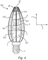
- Figs. 4 and 5 a side view and a top view, respectively, of a lighting device 100 according to a second embodiment of the invention is shown.
- the lighting device 100 shown in Figs. 4 and 5 is very similar to that described above in relation to Figs. 1 to 3 , but differs in the following respects.
- the cover element 2 of the lighting device 100 is only provided with a first plurality of grooves 231, 232, 233 comprising a V-shaped cross-section and being provided in the outer surface 21 of the cover element 2.
- the first plurality of grooves 231, 232, 233 are provided as straight grooves extending along the shortest path from the bottom (not visible on Figs. 2 and 3 ) of the cover element 2 to a position near the top 26 of the cover element 2.
- the cover element 2 of the lighting device 100 is arranged such as to extend over the heat sink element 3 in such a way that each groove of the first plurality of grooves 231, 232, 233 extends in parallel with and directly over a rib of the plurality of ribs 341, 342, 343 of the second part 32 of the heat sink element 3.
- the cover element 2 of the lighting device 100 is provided with a further set of grooves 28 provided near and/or at the top 26 of the cover element 2.
- the grooves 28 may comprise a V-shaped cross-section.
- the further set of grooves 28 have the effect of providing further hiding of the heat sink 3 and in particular of the top element 35 of the heat sink in case such a top element 35 is provided.
- the V-shaped cross-section of the groove 233 comprises two legs 2331, 2332 joined in an apex 2333 in such a way that the two legs 2331, 2332 form an angle ⁇ between them. In one embodiment the angle ⁇ is 90°.
- the groove 233 is arranged such that the apex 2333 points towards the heat sink element 3.
- the groove 233 furthermore comprises a depth measured as the distance from the apex 2333 to a point straight above the apex 2333 and level with the outer surface 21 of the cover element 2.
- each groove of the first plurality of grooves and where present each groove of the second plurality of grooves, comprises a V-shaped cross-section comprising two legs joined in an apex as well as a depth as described above with reference to the groove 233 shown on Fig. 5 , and are also arranged such that their respective apex points towards the heat sink element.
- the angle ⁇ between the two legs of the V-shaped cross section of the grooves may be varied along the length of a groove and/or between grooves and/or between each of the two pluralities of grooves.
- each groove of the first plurality of grooves, and where present each groove of the second plurality of grooves is at least 0.5 mm.
- Fig. 6 a side view of a lighting device 101 according to a third embodiment of the invention is shown.
- the cover element 2 is shown separately for the sake of simplicity, and an enlarged view of a section of the cover element 2 is added for further clarity.
- the lighting device 101 shown in Fig. 6 is similar to that described above in relation to Fig. 1 , but differs at least in the following respects.
- the cover element 2 of the lighting device 101 is provided with a first plurality of ridges 231, 232 and a second plurality of ridges 241, 242 comprising a V-shaped cross-section.
- the height of the ridges of the first and second plurality of ridges is, however, smaller than the depth of the grooves for the previous embodiments described in relation to Figs. 1 to 5 .
- the second plurality of ridges 241, 242 may be omitted.
- first and optionally also a second plurality of ridges with a V-shaped cross-section and being provided on or in an outer surface of the cover element provides for a lighting device with which it becomes possible to visually remove at least a part of the heat sink, i.e. to make at least a part of the heat sink invisible seen from a user's point of view, and which is furthermore highly versatile in terms of design options.
- This effect is for a first and optionally also a second plurality of ridges with a V-shaped cross-section, however, less profound than for grooves.
- the cover element 2 comprises a plurality of surface structures 25 shaped as pyramids.
- the surface structures 25 taper in a direction towards the inner surface 22 of the cover element 2.
- Fig. 7 a side view of a lighting device 102 according to a fourth embodiment of the invention is shown.
- the lighting device 102 shown in Fig. 7 is very similar to that described above in relation to Fig. 2 , but differs at least in the following respects.
- the cover element 2 comprises a first plurality of grooves 231, 232, 233 comprising a V-shaped cross-section.
- both the grooves of the first plurality of grooves 231, 232, 233 and the ribs 341, 342, 343 of the heat sink element 3 extend along a curved or winding path.
- the grooves of the first plurality of grooves 231, 232, 233 extend from the bottom or a position near the bottom of the cover element 2 to a position near the top of the cover element 2.
- the ribs 341, 342, 343 extend from the first part to the top element of the heat sink element 3.
- the cover element 2 of the lighting device 102 is arranged such as to extend over the heat sink element 3 in such a way that each groove of the first plurality of grooves 231, 232, 233 extends in parallel with and directly over a rib of the plurality of ribs 341, 342, 343 of the second part 32 of the heat sink element 3.
- Fig. 8 a side view of a lighting device 103 according to a fifth embodiment of the invention is shown.
- the lighting device 103 shown in Fig. 8 is very similar to that described above in relation to Fig. 1 , but differs at least in the following respects.
- the cover element 2 of the lighting device 101 is provided with a first plurality of grooves comprising a V-shaped cross-section represented by groove 231 and a second plurality of grooves 241, 242 comprising a V-shaped cross-section.
- both the grooves of the first plurality of grooves 231 and the ribs 341 of the heat sink element 3 extend along a curved or winding path.
- the grooves of the first plurality of grooves 231 extend from the bottom or a position near the bottom of the cover element 2 to a position near the top of the cover element 2.
- the ribs 341 extend from the first part to the top element of the heat sink element 3.
- the grooves of the second plurality of grooves 241, 242, however, are straight and extend along the periphery of the cover element 2 in a horizontal or transversal direction T.
Landscapes
- Engineering & Computer Science (AREA)
- General Engineering & Computer Science (AREA)
- Physics & Mathematics (AREA)
- Microelectronics & Electronic Packaging (AREA)
- Optics & Photonics (AREA)
- Non-Portable Lighting Devices Or Systems Thereof (AREA)
- Arrangement Of Elements, Cooling, Sealing, Or The Like Of Lighting Devices (AREA)
Claims (14)
- Beleuchtungsvorrichtung, umfassend:mindestens eine Lichtquelle (4), die angepasst ist, um bei Betrieb Licht zu emittieren,ein Wärmesenkenelement (3), das einen ersten Teil (31), auf dem die mindestens eine Lichtquelle angeordnet ist, und einen zweiten Teil (32) umfasst, wobei der zweite Teil eine Vielzahl von Rippen (341, 342, 343, 344) umfasst, die sich von dem ersten Teil erstrecken, undein Abdeckelement (2), das eine äußere Oberfläche (21) umfasst, die angepasst ist zum Bilden einer Lichtaustrittsoberfläche der Beleuchtungsvorrichtung, dadurch gekennzeichnet, dass das Abdeckelement (2) eine erste Vielzahl von Rillen (231, 232, 233) umfasst, die einen V-förmigen Querschnitt umfassen und in der äußeren Oberfläche des Abdeckelements bereitgestellt sind, wobei das Abdeckelement (2) zusätzlich eine zweite Vielzahl von Rillen (241, 242, 243) umfasst die einen V-förmigen Querschnitt umfassen und in der äußeren Oberfläche (21) des Abdeckelements bereitgestellt sind und so angeordnet sind, dass die Rillen der zweiten Vielzahl von Rillen die Rillen der ersten Vielzahl von Rillen in einem Winkel schneiden, der von null verschieden ist, wobei das Abdeckelement so angeordnet ist, dass es sich in einer Weise über dem Wärmesenkenelement erstreckt, dass sich die erste Vielzahl von Rillen und die zweite Vielzahl von Rillen über der Vielzahl von Rippen des zweiten Teils des Wärmesenkenelements erstrecken.
- Beleuchtungsvorrichtung, umfassend:mindestens eine Lichtquelle (4), die angepasst ist, um bei Betrieb Licht zu emittieren,ein Wärmesenkenelement (3), das einen ersten Teil (31), auf dem die mindestens eine Lichtquelle angeordnet ist, und einen zweiten Teil (32) umfasst, wobei der zweite Teil eine Vielzahl von Rippen (341, 342, 343, 344) umfasst, die sich von dem ersten Teil erstrecken, undein Abdeckelement (2), das eine äußere Oberfläche (21) umfasst, die angepasst ist zum Bilden einer Lichtaustrittsoberfläche der Beleuchtungsvorrichtung, dadurch gekennzeichnet, dass das Abdeckelement (2) eine erste Vielzahl von Rillen (231, 232, 233) umfasst, die einen V-förmigen Querschnitt umfassen und in der äußeren Oberfläche des Abdeckelements bereitgestellt sind, wobei das Abdeckelement so angeordnet ist, dass es sich in einer Weise über dem Wärmesenkenelement erstreckt, dass sich die erste Vielzahl von Rillen über der Vielzahl von Rippen des zweiten Teils des Wärmesenkenelements erstreckt, und in einer Weise, dass sich jede Rille der ersten Vielzahl von Rillen parallel zu und direkt über einer Rippe der Vielzahl von Rippen des zweiten Teils des Wärmesenkenelements erstreckt.
- Beleuchtungsvorrichtung nach Anspruch 1 oder 2, wobei der erste Teil (31) des Wärmesenkenelements eine Vielzahl von Vertiefungen (331, 332) umfasst, die in einer Weise bereitgestellt sind, dass sie sich zwischen den Rippen (341, 342, 343, 344) erstrecken.
- Beleuchtungsvorrichtung nach einem der vorstehenden Ansprüche, wobei der V-förmige Querschnitt jeder Rille der ersten und/oder zweiten Vielzahl von Rillen zwei in einer Spitze (2333) verbundene Schenkel (2331, 2332) umfasst und wobei die erste und/oder zweite Vielzahl von Rillen so angeordnet sind, dass die Spitze zu dem Wärmesenkenelement zeigt.
- Beleuchtungsvorrichtung nach einem der vorstehenden Ansprüche, wobei die Rippen der Vielzahl von Rippen (341, 342, 343, 344) des Wärmesenkenelements in einem Abstand (d) in der Größenordnung von 8 mm beabstandet sind.
- Beleuchtungsvorrichtung nach einem der Ansprüche 1 oder 3 bis 5, wobei das Abdeckelement so angeordnet ist, dass es sich in einer Weise über dem Wärmesenkenelement erstreckt, dass sich jede Rille der Vielzahl von Rillen in einem Winkel von 45° zu und über den Rippen der Vielzahl von Rippen des zweiten Teils des Wärmesenkenelements erstreckt, und in einer Weise, dass sich jede Rille der zweiten Vielzahl von Rillen in einem Winkel, der von null verschieden ist, zu und über den Rippen der Vielzahl von Rippen des zweiten Teils des Wärmesenkenelements erstreckt.
- Beleuchtungsvorrichtung nach einem der vorstehenden Ansprüche, wobei das Abdeckelement (2) einen unteren Abschnitt (27) und einen oberen Abschnitt (26) umfasst und wobei sich mindestens eine der Rillen der ersten und/oder zweiten Vielzahl von Rillen vom unteren Abschnitt oder einer Position nahe dem unteren Abschnitt zum oberen Abschnitt oder einer Position nahe dem oberen Abschnitt erstreckt.
- Beleuchtungsvorrichtung nach einem der vorstehenden Ansprüche, wobei das Abdeckelement (2) einen unteren Abschnitt (27) und einen oberen Abschnitt (26) umfasst und wobei sich mindestens eine der Rippen der Vielzahl von Rippen und die Rillen der ersten und/oder zweiten Vielzahl von Rillen entlang des kürzesten Wegs vom unteren Abschnitt oder einer Position nahe dem unteren Abschnitt zum oberen Abschnitt oder einer Position nahe dem oberen Abschnitt erstrecken.
- Beleuchtungsvorrichtung nach einem der vorstehenden Ansprüche, wobei das Abdeckelement (2) einen unteren Abschnitt (27) und einen oberen Abschnitt (26) umfasst und wobei sich mindestens eine der Rippen der Vielzahl von Rippen und die Rillen der ersten und/oder zweiten Vielzahl von Rillen entlang eines gekrümmten oder gewundenen Wegs vom unteren Abschnitt oder einer Position nahe dem unteren Abschnitt zum oberen Abschnitt oder einer Position nahe dem oberen Abschnitt erstrecken.
- Beleuchtungsvorrichtung nach einem der vorstehenden Ansprüche, wobei das Abdeckelement (2) weiter eine Vielzahl von Oberflächenstrukturen (25) umfasst, die auf der äußeren Oberfläche (21) des Abdeckelements angeordnet sind.
- Beleuchtungsvorrichtung nach Anspruch 10, wobei die Vielzahl von Oberflächenstrukturen (25) als Pyramide oder Pyramidenstumpf geformt ist.
- Beleuchtungsvorrichtung nach Anspruch 11, wobei die Vielzahl als Pyramide oder Pyramidenstumpf geformter Oberflächenstrukturen (25) einen oberen Winkel zwischen 60° und 120° umfasst.
- Beleuchtungsvorrichtung nach einem der Ansprüche 10 bis 12, wobei sich die Vielzahl von Oberflächenstrukturen (25) in eine beliebige einer Richtung zu einer inneren Oberfläche des Abdeckelements und einer Richtung weg von einer inneren Oberfläche des Abdeckelements verjüngt.
- Beleuchtungsvorrichtung nach einem der vorstehenden Ansprüche, wobei der zweite Teil (32) des Wärmesenkenelements (3) weiter ein oberes Element (35) umfasst, das mindestens einige der Rippen (341, 342, 343, 344) der Vielzahl von Rippen an einem dem ersten Teil entgegengesetzten Ende verbindet.
Applications Claiming Priority (2)
| Application Number | Priority Date | Filing Date | Title |
|---|---|---|---|
| EP15196494 | 2015-11-26 | ||
| PCT/EP2016/077668 WO2017089170A1 (en) | 2015-11-26 | 2016-11-15 | A lighting device |
Publications (2)
| Publication Number | Publication Date |
|---|---|
| EP3380781A1 EP3380781A1 (de) | 2018-10-03 |
| EP3380781B1 true EP3380781B1 (de) | 2019-07-10 |
Family
ID=54707607
Family Applications (1)
| Application Number | Title | Priority Date | Filing Date |
|---|---|---|---|
| EP16800907.4A Not-in-force EP3380781B1 (de) | 2015-11-26 | 2016-11-15 | Beleuchtungsvorrichtung |
Country Status (4)
| Country | Link |
|---|---|
| US (1) | US10627096B2 (de) |
| EP (1) | EP3380781B1 (de) |
| CN (1) | CN108291693A (de) |
| WO (1) | WO2017089170A1 (de) |
Families Citing this family (5)
| Publication number | Priority date | Publication date | Assignee | Title |
|---|---|---|---|---|
| USD947422S1 (en) * | 2020-11-23 | 2022-03-29 | Yang Hu | Light with control box |
| USD974598S1 (en) * | 2021-05-20 | 2023-01-03 | Shenzhen Lingtuo Intelligent Technology Co., Ltd. | String light |
| USD960404S1 (en) * | 2021-07-19 | 2022-08-09 | Shao Wang | String light |
| USD1040394S1 (en) * | 2023-01-06 | 2024-08-27 | Dongguan Meiting Electronic Technology Co., Ltd. | String light |
| US12055275B1 (en) * | 2023-05-16 | 2024-08-06 | Xinjiang Zou | String lamp |
Family Cites Families (25)
| Publication number | Priority date | Publication date | Assignee | Title |
|---|---|---|---|---|
| DE2520429C3 (de) * | 1975-05-07 | 1978-05-11 | Siemens Ag, 1000 Berlin Und 8000 Muenchen | Lichtdurchlässige Abdeckung für Leuchten |
| US20060034077A1 (en) * | 2004-08-10 | 2006-02-16 | Tsu-Kang Chang | White light bulb assembly using LED as a light source |
| DE202004012513U1 (de) | 2004-08-10 | 2004-12-16 | Chang, Tsu-Kang | Weiße Lampenbaueinheit, die eine LED als Lichtquelle verwendet |
| CN2831526Y (zh) * | 2005-08-19 | 2006-10-25 | 吴清标 | 组合式装饰灯 |
| EP2245367A4 (de) * | 2008-01-15 | 2015-08-12 | Philip Premysler | Rundstrahl-led-lampe |
| US8948564B1 (en) | 2009-04-16 | 2015-02-03 | Fusion Uptix, Inc. | Spline lamp with opposing light source orientation |
| TWM379534U (en) * | 2009-08-21 | 2010-05-01 | Tong Yah Ind Co Ltd | Vehicular lamp |
| DE102010001046A1 (de) * | 2010-01-20 | 2011-07-21 | Osram Gesellschaft mit beschränkter Haftung, 81543 | Leuchtvorrichtung |
| US8070347B1 (en) * | 2010-06-17 | 2011-12-06 | Gemmy Industries Corporation | Lamp assembly of light-emitting diode string light |
| JP2012064362A (ja) | 2010-09-14 | 2012-03-29 | Sharp Corp | 照明装置 |
| US20120262050A1 (en) | 2011-04-15 | 2012-10-18 | Szu Min Fan | Type of Led Light |
| JP6042873B2 (ja) * | 2011-04-29 | 2016-12-14 | コーニンクレッカ フィリップス エヌ ヴェKoninklijke Philips N.V. | 下位の熱散逸構造を具備するled照明装置 |
| TW201309967A (zh) * | 2011-06-03 | 2013-03-01 | Huizhou Light Engine Ltd | 具有熱傳導燈罩之燈泡 |
| CN202338792U (zh) * | 2011-09-15 | 2012-07-18 | 东莞雷笛克光学有限公司 | 烛灯 |
| JP2013065521A (ja) * | 2011-09-20 | 2013-04-11 | Minebea Co Ltd | 配光制御部材及びそれを用いた照明装置 |
| CN102720961A (zh) | 2012-05-30 | 2012-10-10 | 上舜照明(中国)有限公司 | 一种全空间发光的led蜡烛灯 |
| US9488360B2 (en) | 2012-09-07 | 2016-11-08 | Koninklijke Philips N.V. | Lighting device with integrated lens heat sink |
| CN202972599U (zh) * | 2012-10-19 | 2013-06-05 | 深圳市凯柏光电有限公司 | Led蜡烛灯 |
| US8746953B1 (en) * | 2012-12-28 | 2014-06-10 | Chiliang Shao | Waterproof decorative lamp |
| CN203068233U (zh) * | 2013-02-02 | 2013-07-17 | 广东爱华新光电科技有限公司 | Led球泡灯 |
| US9303857B2 (en) | 2013-02-04 | 2016-04-05 | Cree, Inc. | LED lamp with omnidirectional light distribution |
| US9435492B2 (en) * | 2013-03-15 | 2016-09-06 | Cree, Inc. | LED luminaire with improved thermal management and novel LED interconnecting architecture |
| FR3015002B1 (fr) * | 2013-12-17 | 2018-07-13 | Legrand France | Dispositif d'eclairage |
| CN204153690U (zh) | 2014-10-08 | 2015-02-11 | 浙江新天天光电科技有限公司 | 一种led蜡烛灯 |
| US9702512B2 (en) * | 2015-03-13 | 2017-07-11 | Cree, Inc. | Solid-state lamp with angular distribution optic |
-
2016
- 2016-11-15 CN CN201680069270.5A patent/CN108291693A/zh active Pending
- 2016-11-15 US US15/778,590 patent/US10627096B2/en not_active Expired - Fee Related
- 2016-11-15 EP EP16800907.4A patent/EP3380781B1/de not_active Not-in-force
- 2016-11-15 WO PCT/EP2016/077668 patent/WO2017089170A1/en not_active Ceased
Also Published As
| Publication number | Publication date |
|---|---|
| US20180347799A1 (en) | 2018-12-06 |
| WO2017089170A1 (en) | 2017-06-01 |
| US10627096B2 (en) | 2020-04-21 |
| CN108291693A (zh) | 2018-07-17 |
| EP3380781A1 (de) | 2018-10-03 |
Similar Documents
| Publication | Publication Date | Title |
|---|---|---|
| EP3380781B1 (de) | Beleuchtungsvorrichtung | |
| EP2929238B1 (de) | Flache beleuchtungsvorrichtung | |
| JP3168979U (ja) | 発光ダイオード照明器具 | |
| JP6173476B2 (ja) | 改良型熱伝達装置を含む照明デバイス | |
| US20120307498A1 (en) | Light bulb with thermally conductive glass globe | |
| EP3208522B1 (de) | Omnidirektionale lichtemittierende led-lampe | |
| JP5686198B2 (ja) | 電球形ledランプ | |
| US9863589B2 (en) | Bulb-like LED lamp and manufacturing method thereof | |
| KR20130109458A (ko) | 촛불형 빛을 발산하는 원적외선 방사 엘이디 전구 | |
| JP6129575B2 (ja) | 照明ランプ | |
| US20140334147A1 (en) | Led bulb with a gas medium having a uniform light-distribution profile | |
| CN102135257B (zh) | 节状式灯具 | |
| JP6497501B2 (ja) | 発光装置 | |
| JP6616050B1 (ja) | 浮いた光源を有するランプ | |
| KR101472463B1 (ko) | 엘이디 조명기구 | |
| JP2013229195A (ja) | 電球型照明装置 | |
| JP4970624B1 (ja) | 照明装置 | |
| KR101273627B1 (ko) | 형광등형 엘이디 조명등 | |
| KR20130020535A (ko) | Led 램프 | |
| JP6185310B2 (ja) | カバー取付機構及び照明装置 | |
| WO2014025933A2 (en) | Led bulb with a gas medium having a uniform light-distribution profile | |
| KR20140033871A (ko) | 엘이디 조명 장치 | |
| CN203363717U (zh) | Led灯泡结构 | |
| JP5594549B2 (ja) | 電球形ランプ及びこの電球形ランプを用いた照明器具 | |
| JP2017050266A (ja) | 発光ダイオード式照明装置 |
Legal Events
| Date | Code | Title | Description |
|---|---|---|---|
| STAA | Information on the status of an ep patent application or granted ep patent |
Free format text: STATUS: UNKNOWN |
|
| STAA | Information on the status of an ep patent application or granted ep patent |
Free format text: STATUS: THE INTERNATIONAL PUBLICATION HAS BEEN MADE |
|
| PUAI | Public reference made under article 153(3) epc to a published international application that has entered the european phase |
Free format text: ORIGINAL CODE: 0009012 |
|
| STAA | Information on the status of an ep patent application or granted ep patent |
Free format text: STATUS: REQUEST FOR EXAMINATION WAS MADE |
|
| 17P | Request for examination filed |
Effective date: 20180626 |
|
| AK | Designated contracting states |
Kind code of ref document: A1 Designated state(s): AL AT BE BG CH CY CZ DE DK EE ES FI FR GB GR HR HU IE IS IT LI LT LU LV MC MK MT NL NO PL PT RO RS SE SI SK SM TR |
|
| AX | Request for extension of the european patent |
Extension state: BA ME |
|
| RAP1 | Party data changed (applicant data changed or rights of an application transferred) |
Owner name: PHILIPS LIGHTING HOLDING B.V. |
|
| GRAP | Despatch of communication of intention to grant a patent |
Free format text: ORIGINAL CODE: EPIDOSNIGR1 |
|
| STAA | Information on the status of an ep patent application or granted ep patent |
Free format text: STATUS: GRANT OF PATENT IS INTENDED |
|
| DAV | Request for validation of the european patent (deleted) | ||
| DAX | Request for extension of the european patent (deleted) | ||
| INTG | Intention to grant announced |
Effective date: 20190208 |
|
| RAP1 | Party data changed (applicant data changed or rights of an application transferred) |
Owner name: SIGNIFY HOLDING B.V. |
|
| GRAS | Grant fee paid |
Free format text: ORIGINAL CODE: EPIDOSNIGR3 |
|
| GRAA | (expected) grant |
Free format text: ORIGINAL CODE: 0009210 |
|
| STAA | Information on the status of an ep patent application or granted ep patent |
Free format text: STATUS: THE PATENT HAS BEEN GRANTED |
|
| AK | Designated contracting states |
Kind code of ref document: B1 Designated state(s): AL AT BE BG CH CY CZ DE DK EE ES FI FR GB GR HR HU IE IS IT LI LT LU LV MC MK MT NL NO PL PT RO RS SE SI SK SM TR |
|
| REG | Reference to a national code |
Ref country code: GB Ref legal event code: FG4D |
|
| REG | Reference to a national code |
Ref country code: CH Ref legal event code: EP Ref country code: AT Ref legal event code: REF Ref document number: 1153958 Country of ref document: AT Kind code of ref document: T Effective date: 20190715 |
|
| REG | Reference to a national code |
Ref country code: DE Ref legal event code: R096 Ref document number: 602016016820 Country of ref document: DE |
|
| REG | Reference to a national code |
Ref country code: IE Ref legal event code: FG4D |
|
| REG | Reference to a national code |
Ref country code: NL Ref legal event code: MP Effective date: 20190710 |
|
| REG | Reference to a national code |
Ref country code: LT Ref legal event code: MG4D |
|
| REG | Reference to a national code |
Ref country code: AT Ref legal event code: MK05 Ref document number: 1153958 Country of ref document: AT Kind code of ref document: T Effective date: 20190710 |
|
| PG25 | Lapsed in a contracting state [announced via postgrant information from national office to epo] |
Ref country code: FI Free format text: LAPSE BECAUSE OF FAILURE TO SUBMIT A TRANSLATION OF THE DESCRIPTION OR TO PAY THE FEE WITHIN THE PRESCRIBED TIME-LIMIT Effective date: 20190710 Ref country code: HR Free format text: LAPSE BECAUSE OF FAILURE TO SUBMIT A TRANSLATION OF THE DESCRIPTION OR TO PAY THE FEE WITHIN THE PRESCRIBED TIME-LIMIT Effective date: 20190710 Ref country code: SE Free format text: LAPSE BECAUSE OF FAILURE TO SUBMIT A TRANSLATION OF THE DESCRIPTION OR TO PAY THE FEE WITHIN THE PRESCRIBED TIME-LIMIT Effective date: 20190710 Ref country code: NO Free format text: LAPSE BECAUSE OF FAILURE TO SUBMIT A TRANSLATION OF THE DESCRIPTION OR TO PAY THE FEE WITHIN THE PRESCRIBED TIME-LIMIT Effective date: 20191010 Ref country code: BG Free format text: LAPSE BECAUSE OF FAILURE TO SUBMIT A TRANSLATION OF THE DESCRIPTION OR TO PAY THE FEE WITHIN THE PRESCRIBED TIME-LIMIT Effective date: 20191010 Ref country code: NL Free format text: LAPSE BECAUSE OF FAILURE TO SUBMIT A TRANSLATION OF THE DESCRIPTION OR TO PAY THE FEE WITHIN THE PRESCRIBED TIME-LIMIT Effective date: 20190710 Ref country code: LT Free format text: LAPSE BECAUSE OF FAILURE TO SUBMIT A TRANSLATION OF THE DESCRIPTION OR TO PAY THE FEE WITHIN THE PRESCRIBED TIME-LIMIT Effective date: 20190710 Ref country code: PT Free format text: LAPSE BECAUSE OF FAILURE TO SUBMIT A TRANSLATION OF THE DESCRIPTION OR TO PAY THE FEE WITHIN THE PRESCRIBED TIME-LIMIT Effective date: 20191111 Ref country code: AT Free format text: LAPSE BECAUSE OF FAILURE TO SUBMIT A TRANSLATION OF THE DESCRIPTION OR TO PAY THE FEE WITHIN THE PRESCRIBED TIME-LIMIT Effective date: 20190710 |
|
| PG25 | Lapsed in a contracting state [announced via postgrant information from national office to epo] |
Ref country code: ES Free format text: LAPSE BECAUSE OF FAILURE TO SUBMIT A TRANSLATION OF THE DESCRIPTION OR TO PAY THE FEE WITHIN THE PRESCRIBED TIME-LIMIT Effective date: 20190710 Ref country code: AL Free format text: LAPSE BECAUSE OF FAILURE TO SUBMIT A TRANSLATION OF THE DESCRIPTION OR TO PAY THE FEE WITHIN THE PRESCRIBED TIME-LIMIT Effective date: 20190710 Ref country code: LV Free format text: LAPSE BECAUSE OF FAILURE TO SUBMIT A TRANSLATION OF THE DESCRIPTION OR TO PAY THE FEE WITHIN THE PRESCRIBED TIME-LIMIT Effective date: 20190710 Ref country code: RS Free format text: LAPSE BECAUSE OF FAILURE TO SUBMIT A TRANSLATION OF THE DESCRIPTION OR TO PAY THE FEE WITHIN THE PRESCRIBED TIME-LIMIT Effective date: 20190710 Ref country code: IS Free format text: LAPSE BECAUSE OF FAILURE TO SUBMIT A TRANSLATION OF THE DESCRIPTION OR TO PAY THE FEE WITHIN THE PRESCRIBED TIME-LIMIT Effective date: 20191110 Ref country code: GR Free format text: LAPSE BECAUSE OF FAILURE TO SUBMIT A TRANSLATION OF THE DESCRIPTION OR TO PAY THE FEE WITHIN THE PRESCRIBED TIME-LIMIT Effective date: 20191011 |
|
| PGFP | Annual fee paid to national office [announced via postgrant information from national office to epo] |
Ref country code: FR Payment date: 20191126 Year of fee payment: 4 |
|
| PG25 | Lapsed in a contracting state [announced via postgrant information from national office to epo] |
Ref country code: TR Free format text: LAPSE BECAUSE OF FAILURE TO SUBMIT A TRANSLATION OF THE DESCRIPTION OR TO PAY THE FEE WITHIN THE PRESCRIBED TIME-LIMIT Effective date: 20190710 |
|
| PG25 | Lapsed in a contracting state [announced via postgrant information from national office to epo] |
Ref country code: PL Free format text: LAPSE BECAUSE OF FAILURE TO SUBMIT A TRANSLATION OF THE DESCRIPTION OR TO PAY THE FEE WITHIN THE PRESCRIBED TIME-LIMIT Effective date: 20190710 Ref country code: EE Free format text: LAPSE BECAUSE OF FAILURE TO SUBMIT A TRANSLATION OF THE DESCRIPTION OR TO PAY THE FEE WITHIN THE PRESCRIBED TIME-LIMIT Effective date: 20190710 Ref country code: RO Free format text: LAPSE BECAUSE OF FAILURE TO SUBMIT A TRANSLATION OF THE DESCRIPTION OR TO PAY THE FEE WITHIN THE PRESCRIBED TIME-LIMIT Effective date: 20190710 Ref country code: IT Free format text: LAPSE BECAUSE OF FAILURE TO SUBMIT A TRANSLATION OF THE DESCRIPTION OR TO PAY THE FEE WITHIN THE PRESCRIBED TIME-LIMIT Effective date: 20190710 Ref country code: DK Free format text: LAPSE BECAUSE OF FAILURE TO SUBMIT A TRANSLATION OF THE DESCRIPTION OR TO PAY THE FEE WITHIN THE PRESCRIBED TIME-LIMIT Effective date: 20190710 |
|
| PGFP | Annual fee paid to national office [announced via postgrant information from national office to epo] |
Ref country code: DE Payment date: 20191230 Year of fee payment: 4 |
|
| PG25 | Lapsed in a contracting state [announced via postgrant information from national office to epo] |
Ref country code: SK Free format text: LAPSE BECAUSE OF FAILURE TO SUBMIT A TRANSLATION OF THE DESCRIPTION OR TO PAY THE FEE WITHIN THE PRESCRIBED TIME-LIMIT Effective date: 20190710 Ref country code: IS Free format text: LAPSE BECAUSE OF FAILURE TO SUBMIT A TRANSLATION OF THE DESCRIPTION OR TO PAY THE FEE WITHIN THE PRESCRIBED TIME-LIMIT Effective date: 20200224 Ref country code: SM Free format text: LAPSE BECAUSE OF FAILURE TO SUBMIT A TRANSLATION OF THE DESCRIPTION OR TO PAY THE FEE WITHIN THE PRESCRIBED TIME-LIMIT Effective date: 20190710 Ref country code: CZ Free format text: LAPSE BECAUSE OF FAILURE TO SUBMIT A TRANSLATION OF THE DESCRIPTION OR TO PAY THE FEE WITHIN THE PRESCRIBED TIME-LIMIT Effective date: 20190710 |
|
| REG | Reference to a national code |
Ref country code: DE Ref legal event code: R097 Ref document number: 602016016820 Country of ref document: DE |
|
| REG | Reference to a national code |
Ref country code: CH Ref legal event code: PL |
|
| PLBE | No opposition filed within time limit |
Free format text: ORIGINAL CODE: 0009261 |
|
| STAA | Information on the status of an ep patent application or granted ep patent |
Free format text: STATUS: NO OPPOSITION FILED WITHIN TIME LIMIT |
|
| PG2D | Information on lapse in contracting state deleted |
Ref country code: IS |
|
| PG25 | Lapsed in a contracting state [announced via postgrant information from national office to epo] |
Ref country code: MC Free format text: LAPSE BECAUSE OF FAILURE TO SUBMIT A TRANSLATION OF THE DESCRIPTION OR TO PAY THE FEE WITHIN THE PRESCRIBED TIME-LIMIT Effective date: 20190710 Ref country code: LI Free format text: LAPSE BECAUSE OF NON-PAYMENT OF DUE FEES Effective date: 20191130 Ref country code: LU Free format text: LAPSE BECAUSE OF NON-PAYMENT OF DUE FEES Effective date: 20191115 Ref country code: CH Free format text: LAPSE BECAUSE OF NON-PAYMENT OF DUE FEES Effective date: 20191130 |
|
| 26N | No opposition filed |
Effective date: 20200603 |
|
| REG | Reference to a national code |
Ref country code: BE Ref legal event code: MM Effective date: 20191130 |
|
| PG25 | Lapsed in a contracting state [announced via postgrant information from national office to epo] |
Ref country code: SI Free format text: LAPSE BECAUSE OF FAILURE TO SUBMIT A TRANSLATION OF THE DESCRIPTION OR TO PAY THE FEE WITHIN THE PRESCRIBED TIME-LIMIT Effective date: 20190710 |
|
| PG25 | Lapsed in a contracting state [announced via postgrant information from national office to epo] |
Ref country code: IE Free format text: LAPSE BECAUSE OF NON-PAYMENT OF DUE FEES Effective date: 20191115 |
|
| PG25 | Lapsed in a contracting state [announced via postgrant information from national office to epo] |
Ref country code: BE Free format text: LAPSE BECAUSE OF NON-PAYMENT OF DUE FEES Effective date: 20191130 |
|
| PG25 | Lapsed in a contracting state [announced via postgrant information from national office to epo] |
Ref country code: CY Free format text: LAPSE BECAUSE OF FAILURE TO SUBMIT A TRANSLATION OF THE DESCRIPTION OR TO PAY THE FEE WITHIN THE PRESCRIBED TIME-LIMIT Effective date: 20190710 |
|
| REG | Reference to a national code |
Ref country code: DE Ref legal event code: R119 Ref document number: 602016016820 Country of ref document: DE |
|
| GBPC | Gb: european patent ceased through non-payment of renewal fee |
Effective date: 20201115 |
|
| PG25 | Lapsed in a contracting state [announced via postgrant information from national office to epo] |
Ref country code: MT Free format text: LAPSE BECAUSE OF FAILURE TO SUBMIT A TRANSLATION OF THE DESCRIPTION OR TO PAY THE FEE WITHIN THE PRESCRIBED TIME-LIMIT Effective date: 20190710 Ref country code: HU Free format text: LAPSE BECAUSE OF FAILURE TO SUBMIT A TRANSLATION OF THE DESCRIPTION OR TO PAY THE FEE WITHIN THE PRESCRIBED TIME-LIMIT; INVALID AB INITIO Effective date: 20161115 |
|
| PG25 | Lapsed in a contracting state [announced via postgrant information from national office to epo] |
Ref country code: FR Free format text: LAPSE BECAUSE OF NON-PAYMENT OF DUE FEES Effective date: 20201130 |
|
| PG25 | Lapsed in a contracting state [announced via postgrant information from national office to epo] |
Ref country code: GB Free format text: LAPSE BECAUSE OF NON-PAYMENT OF DUE FEES Effective date: 20201115 Ref country code: DE Free format text: LAPSE BECAUSE OF NON-PAYMENT OF DUE FEES Effective date: 20210601 |
|
| PG25 | Lapsed in a contracting state [announced via postgrant information from national office to epo] |
Ref country code: MK Free format text: LAPSE BECAUSE OF FAILURE TO SUBMIT A TRANSLATION OF THE DESCRIPTION OR TO PAY THE FEE WITHIN THE PRESCRIBED TIME-LIMIT Effective date: 20190710 |