EP3380793B1 - Kit de guidage et retention de matière, notamment liquide - Google Patents
Kit de guidage et retention de matière, notamment liquide Download PDFInfo
- Publication number
- EP3380793B1 EP3380793B1 EP16813008.6A EP16813008A EP3380793B1 EP 3380793 B1 EP3380793 B1 EP 3380793B1 EP 16813008 A EP16813008 A EP 16813008A EP 3380793 B1 EP3380793 B1 EP 3380793B1
- Authority
- EP
- European Patent Office
- Prior art keywords
- kit
- jaw
- profile
- jaws
- film
- Prior art date
- Legal status (The legal status is an assumption and is not a legal conclusion. Google has not performed a legal analysis and makes no representation as to the accuracy of the status listed.)
- Active
Links
Images

Classifications
-
- F—MECHANICAL ENGINEERING; LIGHTING; HEATING; WEAPONS; BLASTING
- F24—HEATING; RANGES; VENTILATING
- F24D—DOMESTIC- OR SPACE-HEATING SYSTEMS, e.g. CENTRAL HEATING SYSTEMS; DOMESTIC HOT-WATER SUPPLY SYSTEMS; ELEMENTS OR COMPONENTS THEREFOR
- F24D19/00—Details
- F24D19/08—Arrangements for drainage, venting or aerating
- F24D19/082—Arrangements for drainage, venting or aerating for water heating systems
- F24D19/088—Draining arrangements
-
- B—PERFORMING OPERATIONS; TRANSPORTING
- B60—VEHICLES IN GENERAL
- B60H—ARRANGEMENTS OF HEATING, COOLING, VENTILATING OR OTHER AIR-TREATING DEVICES SPECIALLY ADAPTED FOR PASSENGER OR GOODS SPACES OF VEHICLES
- B60H1/00—Heating, cooling or ventilating devices
- B60H1/32—Cooling devices
- B60H1/3233—Cooling devices characterised by condensed liquid drainage means
-
- F—MECHANICAL ENGINEERING; LIGHTING; HEATING; WEAPONS; BLASTING
- F25—REFRIGERATION OR COOLING; COMBINED HEATING AND REFRIGERATION SYSTEMS; HEAT PUMP SYSTEMS; MANUFACTURE OR STORAGE OF ICE; LIQUEFACTION SOLIDIFICATION OF GASES
- F25D—REFRIGERATORS; COLD ROOMS; ICE-BOXES; COOLING OR FREEZING APPARATUS NOT OTHERWISE PROVIDED FOR
- F25D21/00—Defrosting; Preventing frosting; Removing condensed or defrost water
- F25D21/06—Removing frost
- F25D21/065—Removing frost by mechanical means
Definitions
- the present invention relates to a kit for guiding and retaining material, in particular liquid.
- the invention applies, in particular, in the fields of plumbing, sweeping or carpentry. More particularly, the invention applies to any field in which a fluid must be guided, in the case of emptying for example.
- the present invention aims to remedy all or part of these drawbacks.
- the present invention relates to a kit according to claim 1.
- the plastic film is held between the jaws and the opening of the first jaw makes it possible to easily guide the device around the source of material, in particular liquid, so that there are no leaks and that all the material is contained in the waterproof bag.
- the device being a guide, the opening is kept raised relative to the film of material. waterproof and only the dimensions of the film limit the storage capacity of the material.
- the curvature of the profile of the first jaw changes sign at least twice.
- the sealed film is well maintained between the jaws of the device and a risk of the film slipping between the jaws is avoided.
- the closed curve is planar.
- the closed curve is generally rectangular in shape.
- the advantage of these embodiments is to have easier handling for the user.
- the handling handle includes material reinforcements.
- the handle can withstand greater bending forces.
- At least one jaw is made of PVC (acronym for “Poly (Vinyl Chloride)”)
- At least one jaw is made by molding.
- the waterproof film includes a drain valve.
- Such sealed films make it possible to guide the liquid from its source to a specific location such as a sewer, or one or more receptacles, by controlling the quantity of liquid poured.
- the waterproof film is made of plastic material at least partially transparent to visible wavelengths.
- the advantage of these embodiments is to allow a user to perceive the limits of the material in the waterproof bag in order to close it to move it without being mistaken.
- the device of the kit that is the subject of the present invention comprises a shovel.
- At least one of the jaws has a generally rectangular shape, the vertices optionally rounded or flattened to form an octagon, the length of the short side of this rectangular shape preferably being between 15 and 25 centimeters.
- At least one of the jaws has a generally rectangular shape, with the tops optionally rounded or flattened to form an octagon, the length of the large side of this rectangular shape preferably being between 21 and 35 centimeters.
- the inventor has determined that these dimensions allow collection over a large area without excessive bulk.
- the device of the kit that is the subject of the present invention is provided with feet.
- the device of the kit that is the subject of the present invention is provided with wires, cords or suspension straps.
- the device of the kit that is the subject of the present invention is provided with a belt.
- the device can be held in the position of use without the user having to hold it by its handle.
- the device of the kit that is the subject of the present invention is provided with a light source, an electrical power supply for this light source and a switch.
- the user can thus illuminate the intervention zone, in particular when it is in the shade, for example behind a water heater, a hot water tank or a radiator, under a sink, a washbasin or a bathtub.
- each characteristic of an embodiment being able to be combined with any other characteristic of any other embodiment in an advantageous manner.
- each parameter of an exemplary embodiment can be implemented independently of other parameters of said exemplary embodiment.
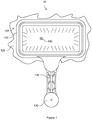
- FIG. 1 is to scale, a schematic view of an embodiment of the guide device 10 of the kit that is the subject of the present invention.
- the guide device 10 comprises, on a closed curve, a peripheral jaw 105, called the “first jaw”, which follows the closed curve or which is intermittent, for example present only in the four straight parts of the closed curve shown in figure 3 .
- the profile 115 of the first jaw 105 has constant dimensions.
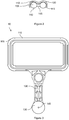
- the first jaw 105 has a section, or profile 105 in the shape of an "8", that is to say two discs 150 connected by a junction 155 thinner than the diameter of the discs.
- the periphery of the device 10 is planar. These embodiments make it easier to position the device against a flat surface, such as a wall, for example.
- the periphery of the device 10 is generally rectangular in shape, with rounded or flattened tops to form an octagon, so that the device 10 is easily placed horizontally against a wall.
- the periphery can be a rectangle.
- the curvature of the section 115 of the first jaw 105 changes sign at least twice.
- the profile 115 of the first jaw is preferably a shape comprising two ends and a junction between the two ends. The junction creating a hollow in the profile 115.
- the ends are in arcs of a circle and the junction has at least one arc of a circle of reverse curvature.
- the first jaw is made of PVC (acronym for “Poly (Vinyl Chloride)”).
- the device 10 comprises a removable jaw 110 called a “second jaw” of profile 120 corresponding, at least partially, to the profile 115 of the first jaw 105, fitting with the first jaw 105 and blocking a film 125 of waterproof material.
- a removable jaw 110 called a “second jaw” of profile 120 corresponding, at least partially, to the profile 115 of the first jaw 105, fitting with the first jaw 105 and blocking a film 125 of waterproof material.
- the flexibility of the material in which the second jaw 110 is made allows the jaw 110 to be deformed by manual support. This elastic deformation allows the second jaw 110 to cross the largest dimension of the profile 115 of the first jaw 105 and to remain in this nested position in which the film 125 is clamped between the two jaws 105 and 110.
- the opening that is to say, the separation of the jaws 105 and 110 is effected by application of reverse manual pressure.
- the profile 120 of the second jaw 110 has constant dimensions over the entire length of the jaw.
- the first and second jaws are each in a plane and of generally rectangular shape, optionally with rounded or flattened tops to form an octagon. These embodiments make it possible to position the second jaw 110 more easily on the first jaw 105.
- the curvature of the profile 120 of the second jaw 110 changes sign at least twice, that is to say has two points of inflection.
- the ends are in circular arcs and the junction comprises at least one arc of a circle of reverse curvature.
- the profile 120 of the first jaw is preferably a shape comprising two ends and a junction between the two ends. Such a change of sign in the curvature of the profile 115 of the first jaw 105, that is to say an inflection point, results in effective clamping of the waterproof film 125.
- the curvature of the profile 120 is similar to the curvature of the profile 115 over at least a part of the profile 120 so that the first and the second jaw, 105 and 110, create a pinch of the waterproof film 125.
- the profile 115 and the profile 120 have an axis of symmetry.
- the second jaw 110 is made of PVC (acronym for “Poly (Vinyl Chloride)”).
- the device 10 comprises a handling handle 130 linked to the first jaw 105, or as a variant to the second jaw 110, to handle the device 10.
- the handling handle 130 is arranged on one of the largest sides of the rectangle defining the closed curve, to limit the moment of the force of gravity due to the material retained in the waterproof film 125.
- the handling handle 130 is elongated.
- the dimensions of the connection of the handling handle 130 to the first jaw 105 are smaller than the dimensions of the handling handle 130 in an axis perpendicular to the connection.
- the handling handle 130 may include material reinforcements 135.
- the material reinforcements 135 are configured to be bending resistant when a force is applied to the first jaw 105.
- the material reinforcements are surplus at the level of the handle. handling 130.
- the material reinforcements 135 form an angle of forty-five degrees with the direction of the bending forces.
- the handling handle 130 may include a circular orifice 145 allowing the device 10 to be suspended from a hook or a point.
- the thickness of the handling handle 130 is less than the dimension of the profiles 115 and 120 nested.
- the first jaw 105 and the second jaw 110 are articulated by a hinge.
- the hinge is preferably on one of the longest sides of the rectangle defining the periphery of the device and the mouth of the bag formed by the film 125 clamped between the jaws 105 and 110.
- This hinge can be a link of thin and elastic material between the first jaw 105 and second jaw 110.
- the hinge may be an interlocking of a shape of the first jaw 105 with a shape of the second jaw 110 configured to create a pivot connection, such as a shaft and a bore, for example.
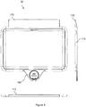
- the second jaw 110 comprises a cover 165 (see figure 5 ) at least partially covering the handling handle 130.
- a cover 165 keeps the two jaws 105 and 110 closed when handling the object in order to keep the sealed film 125 in position.
- At least one jaw, 105 or 110 is made by molding.
- the imprint for the manufacture of the mold corresponds to the first jaw 105 of the device 10 connected to the handling handle 130 and / or to the second jaw 110 of the device 10.
- the waterproof film 125 includes a drain valve 140.
- the drain valve 140 has an operable part configured to control the stopping or flow of the liquid contained in the waterproof bag.
- the drain valve 140 can be connected to means for storing the liquid or for evacuation to sewers.
- the waterproof film 125 is made of a plastic material that is at least partially transparent at visible wavelengths.
- the waterproof film 125 is made of a plasticized textile, a flexible composite material and covered with a plasticized surface or in the form of a metallic film covered with a plasticized surface.
- the dimension of the profiles 115 and 120 nested along an axis perpendicular to the plane of the closed curve is less than one centimeter.
- the device 10 is configured to:
- the device 10 is placed close to the mouth from which the liquid flows. Given the small size and maneuverability of the device 10, the device 10 can easily surround the mouthpiece and prevent any contamination of the surrounding elements.
- the dimensions of the waterproof film 125 which define the capacity of material that can be retained. Since the waterproof film 125 rests on a flat surface such as a floor or a worktop, for example, the material is distributed in the waterproof film 125 under excessive stress for the device 10. Once the material is guided in the waterproof film 125. The waterproof film 125 can be reclosed, detached from the device 10 and moved for disposal. In other embodiments, the waterproof film 125 is drained by means of the drain valve 140.
- the figure 4 shows a kit 20 according to the present invention comprising a guide device 10 and at least one film 125 of waterproof material forming a waterproof bag.
- the dimensions of the film 125 are greater than the dimensions of the jaws of the guide device.
- the film 125 takes the form of a bag, the mouth of which has a perimeter greater than the perimeter of the jaws of the device 10, that is to say of a path passing through all the jaws.
- the perimeter of the mouth of the bag is between 105 and 150% of the perimeter of the jaws of the device 10.
- This squeegee 170 makes it possible to pick up material by sliding this squeegee 170 on a support of this material.
- the squeegee 170 is preferably on the side opposite to the handling handle 130.
- the length, outer edge to outer edge, of the short side of the rectangular part of the device 30 carrying the jaws is preferably between 15 and 25 centimeters and, even more preferably, between 17 and 23 cm. centimeters.
- the length, outer edge to outer edge, of the long side of the rectangular part of the device 30 carrying the jaws is preferably between 21 and 35 centimeters and, even more preferably, between 24 and 32 centimeters.
- the kit that is the subject of the present invention is provided with feet, preferably retractable or removable, so that the device can stand on the ground while holding the mouth of the waterproof film at least twenty centimeters from the ground.
- the kit that is the subject of the present invention is provided with wires, cords or straps, preferably removable, so that the device can be suspended, for example from a radiator by holding the mouth of the waterproof film at least five centimeters from the attachment of wires, ropes or straps.
- the kit that is the subject of the present invention is provided with a belt, preferably removable, so that the device can fit on the hip of a user.
- the fixing between the jaws and the belt requires that the angle between their planes be less than 60 °. In this way, the mouth of the film is kept open and the user can easily dispose of the material in the bag, without needing to open its mouth.
- the kit that is the subject of the present invention is provided with a light source, an electrical power supply for this light source and a switch, preferably positioned on the handling handle, to power the source. from light.
- the user can thus illuminate the intervention zone, for example behind a water heater, a hot water tank or a radiator, under a sink, a washbasin or a bathtub, without occupying one of his hands with a lamp.
- This light source is preferably a light emitting diode.
Landscapes
- Engineering & Computer Science (AREA)
- Physics & Mathematics (AREA)
- Thermal Sciences (AREA)
- Mechanical Engineering (AREA)
- Chemical & Material Sciences (AREA)
- Combustion & Propulsion (AREA)
- General Engineering & Computer Science (AREA)
- Bag Frames (AREA)
- Packages (AREA)
- Containers And Plastic Fillers For Packaging (AREA)
- Refuse Receptacles (AREA)
Description
- La présente invention vise un kit de guidage et rétention de matière, notamment liquide.
- Elle s'applique, notamment, dans les domaines de la plomberie, du ramonage ou de la menuiserie. Plus particulièrement, l'invention s'applique pour tout domaine dans lequel un fluide doit être guidé, dans le cas de vidanges par exemple.
- Actuellement, pour guider un liquide dont la source est difficile d'accès, tel un robinet de purge d'un chauffe-eau ou d'un radiateur, des utilisateurs utilisent des dispositifs rigides difficiles à positionner. De plus, ces dispositifs rigides n'ont pas la dimension ou les formes permettant de les placer proche des angles de murs ou à faible distance du sol. En outre, la rigidité de tels dispositifs limite la quantité de liquide qui peut être contenue dans le dispositif. Donc, si une grande quantité de liquide est à prévoir, le dispositif doit avoir des dimensions considérables ce qui rend la manutention d'un tel dispositif encore moins aisée tant lorsque le dispositif est vide que lorsque le dispositif est au moins partiellement rempli.
- On connaît les documents
FR 3 009 600 US 2004/227347 qui décrivent des dispositifs de rétention d'eau à fixer à des canalisations lors d'interventions. Ces dispositifs sont complexes à utiliser et imposent des manipulations longues. Le documentUS 2004/0227347 divulgue un kit de guidage et de rétention de matière, notamment liquide, qui comporte au moins un dispositif comportant, sur une courbe fermée: - une mâchoire périphérique dite « première mâchoire» présentant un profilé,
- une mâchoire amovible dite « deuxième mâchoire» de profilé correspondant, au moins partiellement, au profilé de la première mâchoire, la mâchoire amovible s'emboîtant, au moins partiellement, avec le profilé de la première mâchoire, et
- une poignée de manutention liée à la première mâchoire pour manipuler le dispositif.
- La présente invention vise à remédier à tout ou partie de ces inconvénients.
- A cet effet, selon un premier aspect, la présente invention vise un kit selon la revendication 1.
- Grâce à ces dispositions, le film plastique est maintenu entre les mâchoires et l'ouverture de la première mâchoire permet de guider aisément le dispositif autour de la source de matière, notamment liquide, afin qu'il n'y ait pas de fuites et que l'intégralité de la matière soit contenue dans le sac étanche. De plus, le dispositif étant un guide, l'ouverture est maintenue surélevée par rapport au film en matériau étanche et seules les dimensions du film limitent la capacité de stockage de la matière.
- Dans des modes de réalisation, la courbure du profilé de la première mâchoire, change au moins deux fois de signe.
- Grâce à ces dispositions, le film étanche est bien maintenu entre les mâchoires du dispositif et un risque de glissement du film entre les mâchoires est évité.
- Dans des modes de réalisation, la courbe fermée est planaire.
- Ces modes de réalisation présentent l'avantage de pouvoir disposer aisément le dispositif autour de surfaces planes tels des murs, par exemple.
- Dans des modes de réalisation, la courbe fermée est de forme générale rectangulaire.
- L'avantage de ces modes de réalisation est d'avoir une manutention plus aisée pour l'utilisateur.
- Dans des modes de réalisation, la poignée de manutention comporte des renforts de matière.
- Grâce à ces dispositions, la poignée peut résister à des efforts de flexion plus importants.
- Dans des modes de réalisation, au moins une mâchoire est en PVC (acronyme de « Poly(Chlorure de Vinyle) »)
- L'avantage de ces modes de réalisation est de rendre le dispositif peu onéreux à la fabrication. De plus, le dispositif est léger et donc plus aisément manipulé par un utilisateur, tout en présentant des caractéristiques techniques suffisantes.
- Dans des modes de réalisation, au moins une mâchoire est fabriquée par moulage.
- Ces modes de réalisation permettent de fabriquer les dispositifs en grande séries.
- Dans des modes de réalisation, le film étanche comporte un robinet de vidange.
- De tels films étanches permettent de guider le liquide, de sa source à un endroit déterminé tel un égout, ou un ou plusieurs récipients, en contrôlant la quantité de liquide versée.
- Dans des modes de réalisation, le film étanche est en matière plastique au moins partiellement transparente aux longueurs d'onde visible.
- L'avantage de ces modes de réalisation est de permettre à un utilisateur de percevoir les limites de la matière dans le sac étanche afin de le refermer pour le déplacer sans se tromper.
- Dans des modes de réalisation, le dispositif du kit objet de la présente invention comporte une pelle.
- Grâce à ces dispositions, par glissement sur une surface supportant une matière à collecter, on collecte une partie de cette matière.
- Dans des modes de réalisation, au moins une des mâchoires présente une forme globalement rectangulaire, aux sommets éventuellement arrondis ou aplatis pour former un octogone, la longueur du petit côté de cette forme rectangulaire étant préférentiellement comprise entre 15 et 25 centimètres.
- Dans des modes de réalisation, au moins une des mâchoires présente une forme globalement rectangulaire, aux sommets éventuellement arrondis ou aplatis pour former un octogone, la longueur du grand côté de cette forme rectangulaire étant préférentiellement comprise entre 21 et 35 centimètres.
- L'inventeur a déterminé que ces dimensions permettent une collecte sur une large surface sans encombrement excessif.
- Dans des modes de réalisation, le dispositif du kit objet de la présente invention est muni de pieds.
- Dans des modes de réalisation, le dispositif du kit objet de la présente invention est muni de fils, cordes ou sangles de suspension.
- Dans des modes de réalisation, le dispositif du kit objet de la présente invention est muni d'une ceinture.
- Grâce à chacune de ces dispositions, le dispositif peut être maintenu en position d'utilisation sans que l'utilisateur n'ait à le tenir par sa poignée.
- Dans des modes de réalisation, le dispositif du kit objet de la présente invention est muni d'une source de lumière, d'une alimentation électrique pour cette source de lumière et d'un interrupteur.
- L'utilisateur peut ainsi éclairer la zone d'intervention, notamment lorsqu'elle est dans l'ombre, par exemple derrière un chauffe-eau, un ballon d'eau chaude ou un radiateur, sous un évier, un lavabo ou une baignoire.
- D'autres avantages, buts et caractéristiques particulières de l'invention ressortiront de la description non limitative qui suit d'au moins un mode de réalisation particulier d'un kit de guidage de matière, notamment un liquide, en regard des dessins annexés, dans lesquels :
- la
figure 1 représente, schématiquement et en plan, un premier mode de réalisation particulier du dispositif du kit objet de la présente invention, - la
figure 2 représente, schématiquement, une section du premier mode de réalisation particulier du dispositif du kit objet de la présente invention, - la
figure 3 représente, schématiquement et en vue de dessous, une troisième vue du premier mode de réalisation particulier du dispositif du kit objet de la présente invention, - la
figure 4 représente, schématiquement et en plan, un premier mode de réalisation particulier d'un kit objet de la présente invention et - la
figure 5 représente, en vue en plan et de côtés, une variante du dispositif illustré enfigures 1 à 3 . - La présente description est donnée à titre non limitatif, chaque caractéristique d'un mode de réalisation pouvant être combinée à toute autre caractéristique de tout autre mode de réalisation de manière avantageuse. Par ailleurs, chaque paramètre d'un exemple de réalisation peut être mis en œuvre indépendamment d'autres paramètres dudit exemple de réalisation.
- On note dès à présent que les figures sont à l'échelle.
- On observe, sur la
figure 1 , qui est à l'échelle, une vue schématique d'un mode de réalisation du dispositif 10 de guidage du kit objet de la présente invention. - Le dispositif 10 de guidage comporte, sur une courbe fermée, une mâchoire périphérique 105, dite « première mâchoire », qui suit la courbe fermée ou qui est intermittente, par exemple présente uniquement dans les quatre parties droites de la courbe fermée représentées en
figure 3 . Préférentiellement, le profilé 115 de la première mâchoire 105 présente des dimensions constantes. Dans le mode de réalisation représenté enfigure 2 , la première mâchoire 105 présente une section, ou profilé 105 en forme de « 8 », c'est-à-dire de deux disques 150 reliés par une jonction 155 plus fine que le diamètre des disques. - Préférentiellement, la périphérie du dispositif 10 est planaire. Ces modes de réalisation permettent de positionner plus aisément le dispositif contre une surface plane, telle un mur, par exemple.
- Préférentiellement, la périphérie du dispositif 10 est de forme générale rectangulaire, à sommets arrondis ou aplatis pour former un octogone, pour que le dispositif 10 soit aisément disposé horizontalement contre un mur. La périphérie peut être un rectangle.
- Dans des modes de réalisation préférentiels, la courbure du profilé 115 de la première mâchoire 105, change au moins deux fois de signe. Le profilé 115 de la première mâchoire est préférentiellement une forme comportant deux extrémités et une jonction entre les deux extrémités. La jonction créant un creux dans le profilé 115. Préférentiellement, les extrémités sont en arcs de cercle et la jonction comporte au moins un arc de cercle de courbure inverse. Un tel changement de signe dans la courbure du profilé 115 de la première mâchoire 105 entraîne un pincement efficace d'un film étanche formant sac de rétention de matière. Préférentiellement, la première mâchoire est en PVC (acronyme de « Poly(Chlorure de Vinyle) »).
- Le dispositif 10 comporte une mâchoire amovible 110 dite «deuxième mâchoire » de profilé 120 correspondant, au moins partiellement, au profilé 115 de la première mâchoire 105, s'emboîtant avec la première mâchoire 105 et bloquant un film 125 en matériau étanche. Préférentiellement, la souplesse de la matière dans laquelle la deuxième mâchoire 110 est réalisée permet à la mâchoire 110 de se déformer par appui manuel. Cette déformation élastique permet à la deuxième mâchoire 110 de franchir la plus grande dimension du profilé 115 de la première mâchoire 105 et de se maintenir dans cette position emboîtée dans laquelle le film 125 est pincé entre les deux mâchoires 105 et 110. L'ouverture, c'est-à-dire la séparation, des mâchoires 105 et 110 se fait par application d'une pression manuelle inverse.
- Préférentiellement, le profilé 120 de la deuxième mâchoire 110 présente des dimensions constantes sur toute la longueur de la mâchoire.
- Préférentiellement, la première et la deuxième mâchoires sont, chacune, dans un plan et de forme générale rectangulaire, éventuellement à sommets arrondis ou aplatis pour former un octogone. Ces modes de réalisation permettent de positionner plus aisément la deuxième mâchoire 110 sur la première mâchoire 105.
- Dans des modes de réalisation préférentiels, la courbure du profilé 120 de la deuxième mâchoire 110, change au moins deux fois de signe, c'est-à-dire présente deux points d'inflexion. Préférentiellement, les extrémités sont en arcs de cercle et la jonction comporte au moins un arc de cercle de courbure inverse. Le profilé 120 de la première mâchoire est préférentiellement une forme comportant deux extrémités et une jonction entre les deux extrémités. Un tel changement de signe dans la courbure du profilé 115 de la première mâchoire 105, c'est-à-dire un point d'inflexion, entraîne un pincement efficace du film étanche 125.
- La courbure du profilé 120 est similaire à la courbure du profilé 115 sur au moins une partie du profilé 120 pour que la première et la deuxième mâchoire, 105 et 110, créent un pincement du filme étanche 125.
- Préférentiellement, le profilé 115 et le profilé 120 présentent un axe de symétrie.
- Préférentiellement, la deuxième mâchoire 110 est en PVC (acronyme de « Poly(Chlorure de Vinyle) »).
- Le dispositif 10 comporte une poignée de manutention 130 liée à la première mâchoire 105, ou en variante à la deuxième mâchoire 110, pour manipuler le dispositif 10. Préférentiellement, la poignée de manutention 130 est disposée sur un des plus grands côtés du rectangle définissant la courbe fermée, pour limiter le moment de la force de pesanteur due à la matière retenue dans le film étanche 125. La poignée de manutention 130 est longiforme. Les dimensions du raccordement de la poignée de manutention 130 à la première mâchoire 105 sont inférieures aux dimensions de la poignée de manutention 130 dans un axe perpendiculaire au raccordement.
- La poignée de manutention 130 peut comporter des renforts de matière 135. Les renforts de matière 135 sont configurés pour être résistants en flexion lorsqu'un effort est appliqué sur la première mâchoire 105. Les renforts de matière sont des surplus au niveau de la poignée de manutention 130. Préférentiellement, pour une meilleure répartition des efforts, les renforts de matière 135 forment un angle à quarante-cinq degrés avec la direction des efforts de flexion.
- La poignée de manutention 130 peut comporter un orifice circulaire 145 permettant de suspendre le dispositif 10 à un crochet ou une pointe. Préférentiellement, l'épaisseur de la poignée de manutention 130 est inférieure à la dimension des profilés 115 et 120 emboîtés.
- Dans des modes de réalisation, la première mâchoire 105 et la deuxième mâchoire 110 sont articulées par une charnière. La charnière est préférentiellement sur un des plus grands côtés du rectangle définissant la périphérie du dispositif et l'embouchure du sac formé par le film 125 pincé entre les mâchoires 105 et 110. Cette charnière peut être un lien de matière de faible épaisseur et élastique entre la première mâchoire 105 et la deuxième mâchoire 110. La charnière peut être un emboitement d'une forme de la première mâchoire 105 avec une forme de la deuxième mâchoire 110 configurés pour créer une liaison pivot, telles, un arbre et un alésage, par exemple.
- Préférentiellement, la deuxième mâchoire 110 comporte un cache 165 (voir
figure 5 ) recouvrant au moins partiellement la poignée de manutention 130. Un tel cache 165 permet de maintenir les deux mâchoires 105 et 110 fermées lors de la manutention de l'objet afin de maintenir le film étanche 125 en position. - Préférentiellement, au moins une mâchoire, 105 ou 110, est fabriquée par moulage. L'empreinte pour la fabrication du moule correspond à la première mâchoire 105 du dispositif 10 raccordé à la poignée de manutention 130 et/ou à la deuxième mâchoire 110 du dispositif 10.
- Dans des modes de réalisation, le film étanche 125 comporte un robinet de vidange 140. Le robinet de vidange 140 comporte une partie actionnable configurée pour contrôler l'arrêt ou l'écoulement du liquide contenu dans le sac étanche. Par exemple, le robinet de vidange 140 peut être raccordé à des moyens de stockage du liquide ou d'évacuation vers des égouts.
- Préférentiellement, le film étanche 125 est en matière plastique au moins partiellement transparente aux longueurs d'onde visible.
- Dans des modes de réalisation, le film étanche 125 est en textile plastifié, en matériau composite souple et recouvert d'une surface plastifiée ou sous la forme d'un film métallique recouvert d'une surface plastifiée.
- Préférentiellement, la dimension des profilés 115 et 120 emboités selon un axe perpendiculaire au plan de la courbe fermée est inférieure à un centimètre.
- Dans des modes de réalisation préférentielles, le dispositif 10
- Le dispositif 10 peut être utilisé dans le cas suivants :
- la vidange de radiateurs,
- la vidange de clarinette de plancher chauffant,
- la vidange de clarinette d'eau chaude ou d'eau froide,
- la vidange de chauffe-eau,
- la vidange d'un ballon de chaudière située proche du sol,
- le nettoyage de siphons de plomberie,
- la purge de radiateurs, dans un angle de murs, par exemple,
- le nettoyage d'un siphon d'un appareil électroménager nécessitant la circulation d'un liquide, tels les machines à laver le linge ou la vaisselle,
- la vidange d'une chaudière à gaz,
- le nettoyage d'un filtre à fioul dans une chaudière à mazout ou
- la purge ou vidange d'éléments automobiles, tels les tambours de freins, par exemple.
- Dans les cas cités ci-dessus, le dispositif 10 est placé proche de l'embouchure de laquelle le liquide s'écoule. Etant donné les faibles dimensions et la maniabilité du dispositif 10, le dispositif 10 peut facilement entourer l'embouchure et éviter toute souillure des éléments environnants.
- De plus, ce sont les dimensions du film étanche 125 qui définissent la capacité de matière qui peut être retenue. Puisque le film étanche 125 repose sur une surface plane tel un sol ou un plan de travail, par exemple, la matière se réparti dans le film étanche 125 dans contraintes excessives pour le dispositif 10. Une fois la matière guidée dans le film étanche 125. Le film étanche 125 peut être refermé, détaché du dispositif 10 et déplacé pour être jeté. Dans d'autres modes de réalisation, le film étanche 125 est vidangé au moyen du robinet de vidange 140.
- La
figure 4 représente un kit 20 selon la présente invention comportant un dispositif de guidage 10 et au moins un film 125 en matériau étanche formant un sac étanche. Les dimensions du film 125 sont supérieures aux dimensions des mâchoires du dispositif de guidage. Selon l'invention, le film 125 prend la forme d'un sac, dont l'embouchure présente un périmètre supérieur au périmètre des mâchoires du dispositif 10, c'est-à-dire d'un chemin passant par toutes les mâchoires. Préférentiellement, le périmètre de l'embouchure du sac est compris entre 105 et 150 % du périmètre des mâchoires du dispositif 10. - On observe, en
figure 5 , une variante 30 du dispositif 10, qui comporte une pelle, ou raclette, 170 pour racler un support. Cette raclette 170 permet de ramasser de la matière en faisant glisser cette raclette 170 sur un support de cette matière. La raclette 170 est, préférentiellement, du côté opposé à la poignée de manutention 130. - La longueur, bord externe à bord externe, du petit côté de la partie rectangulaire du dispositif 30 portant les mâchoires est préférentiellement comprise entre 15 et 25 centimètres et, encore plus préférentiellement, entre 17 et 23 centimètres. La longueur, bord externe à bord externe, du grand côté de la partie rectangulaire du dispositif 30 portant les mâchoires est préférentiellement comprise entre 21 et 35 centimètres et, encore plus préférentiellement, entre 24 et 32 centimètres.
- Dans des modes de réalisation, le kit objet de la présente invention est muni de pieds, préférentiellement escamotables ou amovibles, pour que le dispositif puisse tenir sur le sol en tenant l'embouchure du film étanche à au moins vingt centimètres du sol.
- Dans des modes de réalisation, le kit objet de la présente invention est muni de fils, cordes ou sangles, préférentiellement amovibles, pour que le dispositif puisse être suspendu, par exemple à un radiateur en tenant l'embouchure du film étanche à au moins cinq centimètres de la fixation des fils, cordes ou sangles.
- Dans des modes de réalisation, le kit objet de la présente invention est muni d'une ceinture, préférentiellement amovible, pour que le dispositif puisse tenir sur la hanche d'un utilisateur. Préférentiellement la fixation entre les mâchoires et la ceinture impose que l'angle entre leurs plans soit inférieur à 60°. De cette manière, l'embouchure du film est maintenue ouverte et l'utilisateur peut facilement disposer la matière dans le sac, sans avoir besoin d'ouvrir son embouchure.
- Dans des modes de réalisation, le kit objet de la présente invention est muni d'une source de lumière, d'une alimentation électrique pour cette source de lumière et d'un interrupteur, préférentiellement positionné sur la poignée de manutention, pour alimenter la source de lumière. L'utilisateur peut ainsi éclairer la zone d'intervention, par exemple derrière un chauffe-eau, un ballon d'eau chaude ou un radiateur, sous un évier, un lavabo ou une baignoire, sans occuper une de ses mains avec une lampe. Cette source de lumière est, préférentiellement, une diode électroluminescente.
Claims (15)
- Kit (20) de guidage et rétention de matière, notamment liquide, comportant :- au moins un sac formé par un film en matériau étanche (125) et- au moins un dispositif (10, 30) comportant, sur une courbe fermée :le sac possédant un périmètre d'ouverture supérieur au périmètre des mâchoires du dispositif.- une mâchoire périphérique (105) dite « première mâchoire » présentant un profilé (115),- une mâchoire amovible (110) dite « deuxième mâchoire » de profilé (120) correspondant, au moins partiellement, au profilé (115) de la première mâchoire (105), la mâchoire amovible s'emboîtant, au moins partiellement, autour du profilé (115) de la première mâchoire (105), pour pincer le film (125) entre lesdits profilés et- une poignée de manutention (130) solidaire d'au moins une des mâchoires pour manipuler le dispositif ;
- Kit (20) selon la revendication 1, dans lequel la courbure du profilé (115) de la première mâchoire (105), change au moins deux fois de signe.
- Kit (20) selon l'une des revendications 1 ou 2, dans lequel la courbe fermée est planaire.
- Kit (20) selon l'une des revendications 1 à 3, dans lequel la courbe fermée est de forme générale rectangulaire.
- Kit (20) selon l'une des revendications 1 à 4, dans lequel le dispositif (10, 30) comporte une pelle (170).
- Kit (20) selon l'une des revendications 1 à 5, dans lequel au moins une des mâchoires (105, 110) présente une forme globalement rectangulaire, la longueur du petit côté de cette forme rectangulaire étant préférentiellement comprise entre 15 et 25 centimètres.
- Kit (20) selon l'une des revendications 1 à 6, dans lequel au moins une des mâchoires (105, 110) présente une forme globalement rectangulaire, la longueur du grand côté de cette forme rectangulaire étant préférentiellement comprise entre 21 et 35 centimètres.
- Kit (20) selon l'une des revendications 1 à 7, dans lequel le dispositif est muni de pieds.
- Kit (20) selon l'une des revendications 1 à 8, dans lequel le dispositif est muni de fils, cordes ou sangles de suspension.
- Kit (20) selon l'une des revendications 1 à 9, dans lequel le dispositif est muni d'une ceinture.
- Kit (20) selon l'une des revendications 1 à 10, dans lequel le dispositif est muni d'une source de lumière, d'une alimentation électrique pour cette source de lumière et d'un interrupteur.
- Kit (20) selon l'une des revendications 1 à 11, dans lequel le périmètre de l'embouchure du sac en matériau étanche (125) est compris entre 105 et 150 % du périmètre des mâchoires du dispositif (10).
- Kit (20) selon l'une des revendications 1 à 12, dans lequel le sac formé par un film en matériau étanche (125) comporte un robinet de vidange (140).
- Kit (20) selon l'une des revendications 1 à 13, dans lequel le sac formé par un film en matériau étanche (125) est en matière plastique au moins partiellement transparente aux longueurs d'onde visible.
- Kit (20) selon l'une des revendications 1 à 14, dans lequel au moins une mâchoire (105, 110) est fabriquée par moulage.
Applications Claiming Priority (2)
| Application Number | Priority Date | Filing Date | Title |
|---|---|---|---|
| FR1561272A FR3043989B1 (fr) | 2015-11-23 | 2015-11-23 | Dispositif de guidage d'un liquide, un film pour un tel dispositif et kit comportant un tel dispositif |
| PCT/FR2016/053062 WO2017089704A1 (fr) | 2015-11-23 | 2016-11-23 | Dispositif de guidage de matière, notamment liquide, film pour un tel dispositif et kit comportant un tel dispositif |
Publications (2)
| Publication Number | Publication Date |
|---|---|
| EP3380793A1 EP3380793A1 (fr) | 2018-10-03 |
| EP3380793B1 true EP3380793B1 (fr) | 2020-07-29 |
Family
ID=55182395
Family Applications (1)
| Application Number | Title | Priority Date | Filing Date |
|---|---|---|---|
| EP16813008.6A Active EP3380793B1 (fr) | 2015-11-23 | 2016-11-23 | Kit de guidage et retention de matière, notamment liquide |
Country Status (5)
| Country | Link |
|---|---|
| US (1) | US20180340698A1 (fr) |
| EP (1) | EP3380793B1 (fr) |
| ES (1) | ES2826410T3 (fr) |
| FR (1) | FR3043989B1 (fr) |
| WO (1) | WO2017089704A1 (fr) |
Family Cites Families (16)
| Publication number | Priority date | Publication date | Assignee | Title |
|---|---|---|---|---|
| US5031948A (en) * | 1989-10-03 | 1991-07-16 | Idea Development, Inc. | Bag handling system |
| GB9206343D0 (en) * | 1992-03-24 | 1992-05-06 | Mills Frederick | Apparatus for fluid drainage |
| US5836553A (en) * | 1996-02-08 | 1998-11-17 | Bergaila; Steven W. | Folding bag holder |
| US5913496A (en) * | 1996-07-11 | 1999-06-22 | Valdez; Victor G. | Snap-ring stiffener apparatus having a scoop-like edge and method for stiffening bag openings and other flexible fabrics |
| US20040227347A1 (en) * | 2003-05-12 | 2004-11-18 | Fundin Robert Lyle | Adaptable water diverting fixture |
| US20060027475A1 (en) * | 2004-07-21 | 2006-02-09 | James Gleason | Tool storage and carrier assembly |
| US20060078411A1 (en) * | 2004-10-08 | 2006-04-13 | Maria Casab | Mountable refuse container |
| ES2315971T3 (es) * | 2006-07-31 | 2009-04-01 | Italia Stampi S.R.L. | Soporte para bolsas abiertas. |
| US20090230258A1 (en) * | 2008-03-11 | 2009-09-17 | Mcfadden Jeff Noel | Portable tree or pole/post mounted recreational trash bag holder with lid |
| US9328915B2 (en) * | 2010-09-30 | 2016-05-03 | Black & Decker Inc. | Lighted power tool |
| US9028088B2 (en) * | 2010-09-30 | 2015-05-12 | Black & Decker Inc. | Lighted power tool |
| US8267358B1 (en) * | 2011-05-10 | 2012-09-18 | Letson Philip D | Bag holder |
| US20130108190A1 (en) * | 2011-10-31 | 2013-05-02 | Unique Necessities, Llc | Trash bag supporting device |
| US8919708B1 (en) * | 2012-06-05 | 2014-12-30 | Robert Graves | Dustpan with garbage bag supporting frame, filter, and running boards |
| FR3009600B1 (fr) * | 2013-08-12 | 2015-09-18 | Soletanche Freyssinet | Dispositif de confinement pour une intervention sur une tuyauterie et procede associe |
| US20190062048A1 (en) * | 2017-08-27 | 2019-02-28 | Jesus M. Ortiz Torres | Trash bag holder |
-
2015
- 2015-11-23 FR FR1561272A patent/FR3043989B1/fr not_active Expired - Fee Related
-
2016
- 2016-11-23 EP EP16813008.6A patent/EP3380793B1/fr active Active
- 2016-11-23 ES ES16813008T patent/ES2826410T3/es active Active
- 2016-11-23 WO PCT/FR2016/053062 patent/WO2017089704A1/fr not_active Ceased
- 2016-11-23 US US15/778,201 patent/US20180340698A1/en not_active Abandoned
Non-Patent Citations (1)
| Title |
|---|
| None * |
Also Published As
| Publication number | Publication date |
|---|---|
| FR3043989A1 (fr) | 2017-05-26 |
| ES2826410T3 (es) | 2021-05-18 |
| US20180340698A1 (en) | 2018-11-29 |
| WO2017089704A1 (fr) | 2017-06-01 |
| FR3043989B1 (fr) | 2020-03-20 |
| EP3380793A1 (fr) | 2018-10-03 |
Similar Documents
| Publication | Publication Date | Title |
|---|---|---|
| CA2816196C (fr) | Outil d'assemblage de tuyaux | |
| FR3026420A1 (fr) | Caniveau et receveur de douche | |
| WO2003029552A1 (fr) | Fer a cavite arriere ouverte | |
| FR2808457A1 (fr) | Filtre exterieur a un bac, notamment a un aquarium | |
| EP3088599B1 (fr) | Appareil électroménager de repassage comportant un générateur de vapeur muni d'un orifice de vidange | |
| EP3380793A1 (fr) | Dispositif de guidage de matière, notamment liquide, film pour un tel dispositif et kit comportant un tel dispositif | |
| FR3070586A1 (fr) | Bouilloire munie d'au moins deux debits de versage | |
| EP3581704A1 (fr) | Appareil de traitement du linge à la vapeur comportant une planche de repassage | |
| EP3327196B1 (fr) | Appareil de repassage | |
| EP2609942A1 (fr) | Dispositif anti retour de fluides incorporé dans un ensemble d'expression de lait maternel | |
| FR3044379A1 (fr) | Dispositif de maintien en position d'un tuyau a auto-serrage | |
| FR2565814A1 (fr) | Evier de cuisine | |
| CA3002115A1 (fr) | Robot de cuisine avec bain-marie | |
| EP2829665B1 (fr) | Dispositif de remplissage et d'évacuation d'eau pour appareil sanitaire | |
| EP3524107B1 (fr) | Appareil de cuisine comportant une bonde de vidange commandee par une commande hydraulique | |
| FR2818513A1 (fr) | Dispositif de fixation d'un manche de pinceau a un recipient | |
| FR2910915A1 (fr) | Dispositif variable anti remontees d'odeurs | |
| FR2527452A1 (fr) | Tube souple d'evacuation et recipient collecteur d'urine | |
| FR3134590A1 (fr) | Système de distribution d’eau pour ablution | |
| FR3138992A1 (fr) | Moyen de détection de pression pour appareil de cuisson et appareil de cuisson | |
| FR2997004A1 (fr) | Dispositif d'aspirateur concu apte a l'aspiration d'air et de liquide | |
| CA3156461A1 (fr) | Appareil de stomie | |
| FR2732214A1 (fr) | Dispositif assurant l'etancheite temporaire d'une tetine de biberon | |
| BE889738A (fr) | Organe de prehension pour une douche a main destinee a un lavabo pour enfants. | |
| FR3027880A1 (fr) | Ouvreur de sachet equipant un dilueur gravimetrique |
Legal Events
| Date | Code | Title | Description |
|---|---|---|---|
| STAA | Information on the status of an ep patent application or granted ep patent |
Free format text: STATUS: UNKNOWN |
|
| STAA | Information on the status of an ep patent application or granted ep patent |
Free format text: STATUS: THE INTERNATIONAL PUBLICATION HAS BEEN MADE |
|
| PUAI | Public reference made under article 153(3) epc to a published international application that has entered the european phase |
Free format text: ORIGINAL CODE: 0009012 |
|
| STAA | Information on the status of an ep patent application or granted ep patent |
Free format text: STATUS: REQUEST FOR EXAMINATION WAS MADE |
|
| 17P | Request for examination filed |
Effective date: 20180620 |
|
| AK | Designated contracting states |
Kind code of ref document: A1 Designated state(s): AL AT BE BG CH CY CZ DE DK EE ES FI FR GB GR HR HU IE IS IT LI LT LU LV MC MK MT NL NO PL PT RO RS SE SI SK SM TR |
|
| AX | Request for extension of the european patent |
Extension state: BA ME |
|
| DAV | Request for validation of the european patent (deleted) | ||
| DAX | Request for extension of the european patent (deleted) | ||
| GRAP | Despatch of communication of intention to grant a patent |
Free format text: ORIGINAL CODE: EPIDOSNIGR1 |
|
| STAA | Information on the status of an ep patent application or granted ep patent |
Free format text: STATUS: GRANT OF PATENT IS INTENDED |
|
| INTG | Intention to grant announced |
Effective date: 20200213 |
|
| GRAS | Grant fee paid |
Free format text: ORIGINAL CODE: EPIDOSNIGR3 |
|
| GRAA | (expected) grant |
Free format text: ORIGINAL CODE: 0009210 |
|
| STAA | Information on the status of an ep patent application or granted ep patent |
Free format text: STATUS: THE PATENT HAS BEEN GRANTED |
|
| AK | Designated contracting states |
Kind code of ref document: B1 Designated state(s): AL AT BE BG CH CY CZ DE DK EE ES FI FR GB GR HR HU IE IS IT LI LT LU LV MC MK MT NL NO PL PT RO RS SE SI SK SM TR |
|
| REG | Reference to a national code |
Ref country code: CH Ref legal event code: EP |
|
| REG | Reference to a national code |
Ref country code: AT Ref legal event code: REF Ref document number: 1296249 Country of ref document: AT Kind code of ref document: T Effective date: 20200815 |
|
| REG | Reference to a national code |
Ref country code: IE Ref legal event code: FG4D Free format text: LANGUAGE OF EP DOCUMENT: FRENCH |
|
| REG | Reference to a national code |
Ref country code: DE Ref legal event code: R096 Ref document number: 602016040972 Country of ref document: DE |
|
| REG | Reference to a national code |
Ref country code: LT Ref legal event code: MG4D |
|
| REG | Reference to a national code |
Ref country code: NL Ref legal event code: MP Effective date: 20200729 |
|
| REG | Reference to a national code |
Ref country code: AT Ref legal event code: MK05 Ref document number: 1296249 Country of ref document: AT Kind code of ref document: T Effective date: 20200729 |
|
| PG25 | Lapsed in a contracting state [announced via postgrant information from national office to epo] |
Ref country code: SE Free format text: LAPSE BECAUSE OF FAILURE TO SUBMIT A TRANSLATION OF THE DESCRIPTION OR TO PAY THE FEE WITHIN THE PRESCRIBED TIME-LIMIT Effective date: 20200729 Ref country code: PT Free format text: LAPSE BECAUSE OF FAILURE TO SUBMIT A TRANSLATION OF THE DESCRIPTION OR TO PAY THE FEE WITHIN THE PRESCRIBED TIME-LIMIT Effective date: 20201130 Ref country code: NO Free format text: LAPSE BECAUSE OF FAILURE TO SUBMIT A TRANSLATION OF THE DESCRIPTION OR TO PAY THE FEE WITHIN THE PRESCRIBED TIME-LIMIT Effective date: 20201029 Ref country code: AT Free format text: LAPSE BECAUSE OF FAILURE TO SUBMIT A TRANSLATION OF THE DESCRIPTION OR TO PAY THE FEE WITHIN THE PRESCRIBED TIME-LIMIT Effective date: 20200729 Ref country code: FI Free format text: LAPSE BECAUSE OF FAILURE TO SUBMIT A TRANSLATION OF THE DESCRIPTION OR TO PAY THE FEE WITHIN THE PRESCRIBED TIME-LIMIT Effective date: 20200729 Ref country code: LT Free format text: LAPSE BECAUSE OF FAILURE TO SUBMIT A TRANSLATION OF THE DESCRIPTION OR TO PAY THE FEE WITHIN THE PRESCRIBED TIME-LIMIT Effective date: 20200729 Ref country code: HR Free format text: LAPSE BECAUSE OF FAILURE TO SUBMIT A TRANSLATION OF THE DESCRIPTION OR TO PAY THE FEE WITHIN THE PRESCRIBED TIME-LIMIT Effective date: 20200729 Ref country code: BG Free format text: LAPSE BECAUSE OF FAILURE TO SUBMIT A TRANSLATION OF THE DESCRIPTION OR TO PAY THE FEE WITHIN THE PRESCRIBED TIME-LIMIT Effective date: 20201029 Ref country code: GR Free format text: LAPSE BECAUSE OF FAILURE TO SUBMIT A TRANSLATION OF THE DESCRIPTION OR TO PAY THE FEE WITHIN THE PRESCRIBED TIME-LIMIT Effective date: 20201030 |
|
| PG25 | Lapsed in a contracting state [announced via postgrant information from national office to epo] |
Ref country code: PL Free format text: LAPSE BECAUSE OF FAILURE TO SUBMIT A TRANSLATION OF THE DESCRIPTION OR TO PAY THE FEE WITHIN THE PRESCRIBED TIME-LIMIT Effective date: 20200729 Ref country code: RS Free format text: LAPSE BECAUSE OF FAILURE TO SUBMIT A TRANSLATION OF THE DESCRIPTION OR TO PAY THE FEE WITHIN THE PRESCRIBED TIME-LIMIT Effective date: 20200729 Ref country code: LV Free format text: LAPSE BECAUSE OF FAILURE TO SUBMIT A TRANSLATION OF THE DESCRIPTION OR TO PAY THE FEE WITHIN THE PRESCRIBED TIME-LIMIT Effective date: 20200729 Ref country code: IS Free format text: LAPSE BECAUSE OF FAILURE TO SUBMIT A TRANSLATION OF THE DESCRIPTION OR TO PAY THE FEE WITHIN THE PRESCRIBED TIME-LIMIT Effective date: 20201129 |
|
| PG25 | Lapsed in a contracting state [announced via postgrant information from national office to epo] |
Ref country code: NL Free format text: LAPSE BECAUSE OF FAILURE TO SUBMIT A TRANSLATION OF THE DESCRIPTION OR TO PAY THE FEE WITHIN THE PRESCRIBED TIME-LIMIT Effective date: 20200729 |
|
| PG25 | Lapsed in a contracting state [announced via postgrant information from national office to epo] |
Ref country code: CZ Free format text: LAPSE BECAUSE OF FAILURE TO SUBMIT A TRANSLATION OF THE DESCRIPTION OR TO PAY THE FEE WITHIN THE PRESCRIBED TIME-LIMIT Effective date: 20200729 Ref country code: DK Free format text: LAPSE BECAUSE OF FAILURE TO SUBMIT A TRANSLATION OF THE DESCRIPTION OR TO PAY THE FEE WITHIN THE PRESCRIBED TIME-LIMIT Effective date: 20200729 Ref country code: RO Free format text: LAPSE BECAUSE OF FAILURE TO SUBMIT A TRANSLATION OF THE DESCRIPTION OR TO PAY THE FEE WITHIN THE PRESCRIBED TIME-LIMIT Effective date: 20200729 Ref country code: SM Free format text: LAPSE BECAUSE OF FAILURE TO SUBMIT A TRANSLATION OF THE DESCRIPTION OR TO PAY THE FEE WITHIN THE PRESCRIBED TIME-LIMIT Effective date: 20200729 Ref country code: EE Free format text: LAPSE BECAUSE OF FAILURE TO SUBMIT A TRANSLATION OF THE DESCRIPTION OR TO PAY THE FEE WITHIN THE PRESCRIBED TIME-LIMIT Effective date: 20200729 |
|
| REG | Reference to a national code |
Ref country code: DE Ref legal event code: R097 Ref document number: 602016040972 Country of ref document: DE |
|
| REG | Reference to a national code |
Ref country code: ES Ref legal event code: FG2A Ref document number: 2826410 Country of ref document: ES Kind code of ref document: T3 Effective date: 20210518 |
|
| PG25 | Lapsed in a contracting state [announced via postgrant information from national office to epo] |
Ref country code: AL Free format text: LAPSE BECAUSE OF FAILURE TO SUBMIT A TRANSLATION OF THE DESCRIPTION OR TO PAY THE FEE WITHIN THE PRESCRIBED TIME-LIMIT Effective date: 20200729 |
|
| PLBE | No opposition filed within time limit |
Free format text: ORIGINAL CODE: 0009261 |
|
| STAA | Information on the status of an ep patent application or granted ep patent |
Free format text: STATUS: NO OPPOSITION FILED WITHIN TIME LIMIT |
|
| PG25 | Lapsed in a contracting state [announced via postgrant information from national office to epo] |
Ref country code: MC Free format text: LAPSE BECAUSE OF FAILURE TO SUBMIT A TRANSLATION OF THE DESCRIPTION OR TO PAY THE FEE WITHIN THE PRESCRIBED TIME-LIMIT Effective date: 20200729 Ref country code: SK Free format text: LAPSE BECAUSE OF FAILURE TO SUBMIT A TRANSLATION OF THE DESCRIPTION OR TO PAY THE FEE WITHIN THE PRESCRIBED TIME-LIMIT Effective date: 20200729 |
|
| 26N | No opposition filed |
Effective date: 20210430 |
|
| PG25 | Lapsed in a contracting state [announced via postgrant information from national office to epo] |
Ref country code: LU Free format text: LAPSE BECAUSE OF NON-PAYMENT OF DUE FEES Effective date: 20201123 |
|
| PG25 | Lapsed in a contracting state [announced via postgrant information from national office to epo] |
Ref country code: SI Free format text: LAPSE BECAUSE OF FAILURE TO SUBMIT A TRANSLATION OF THE DESCRIPTION OR TO PAY THE FEE WITHIN THE PRESCRIBED TIME-LIMIT Effective date: 20200729 |
|
| PG25 | Lapsed in a contracting state [announced via postgrant information from national office to epo] |
Ref country code: IE Free format text: LAPSE BECAUSE OF NON-PAYMENT OF DUE FEES Effective date: 20201123 |
|
| PGFP | Annual fee paid to national office [announced via postgrant information from national office to epo] |
Ref country code: CH Payment date: 20211126 Year of fee payment: 6 Ref country code: BE Payment date: 20211130 Year of fee payment: 6 |
|
| PG25 | Lapsed in a contracting state [announced via postgrant information from national office to epo] |
Ref country code: TR Free format text: LAPSE BECAUSE OF FAILURE TO SUBMIT A TRANSLATION OF THE DESCRIPTION OR TO PAY THE FEE WITHIN THE PRESCRIBED TIME-LIMIT Effective date: 20200729 Ref country code: MT Free format text: LAPSE BECAUSE OF FAILURE TO SUBMIT A TRANSLATION OF THE DESCRIPTION OR TO PAY THE FEE WITHIN THE PRESCRIBED TIME-LIMIT Effective date: 20200729 Ref country code: CY Free format text: LAPSE BECAUSE OF FAILURE TO SUBMIT A TRANSLATION OF THE DESCRIPTION OR TO PAY THE FEE WITHIN THE PRESCRIBED TIME-LIMIT Effective date: 20200729 |
|
| PG25 | Lapsed in a contracting state [announced via postgrant information from national office to epo] |
Ref country code: MK Free format text: LAPSE BECAUSE OF FAILURE TO SUBMIT A TRANSLATION OF THE DESCRIPTION OR TO PAY THE FEE WITHIN THE PRESCRIBED TIME-LIMIT Effective date: 20200729 |
|
| REG | Reference to a national code |
Ref country code: CH Ref legal event code: PL |
|
| REG | Reference to a national code |
Ref country code: BE Ref legal event code: MM Effective date: 20221130 |
|
| PG25 | Lapsed in a contracting state [announced via postgrant information from national office to epo] |
Ref country code: LI Free format text: LAPSE BECAUSE OF NON-PAYMENT OF DUE FEES Effective date: 20221130 Ref country code: CH Free format text: LAPSE BECAUSE OF NON-PAYMENT OF DUE FEES Effective date: 20221130 |
|
| PG25 | Lapsed in a contracting state [announced via postgrant information from national office to epo] |
Ref country code: BE Free format text: LAPSE BECAUSE OF NON-PAYMENT OF DUE FEES Effective date: 20221130 |
|
| PGFP | Annual fee paid to national office [announced via postgrant information from national office to epo] |
Ref country code: GB Payment date: 20231129 Year of fee payment: 8 |
|
| PGFP | Annual fee paid to national office [announced via postgrant information from national office to epo] |
Ref country code: DE Payment date: 20241206 Year of fee payment: 9 |
|
| GBPC | Gb: european patent ceased through non-payment of renewal fee |
Effective date: 20241123 |
|
| PG25 | Lapsed in a contracting state [announced via postgrant information from national office to epo] |
Ref country code: GB Free format text: LAPSE BECAUSE OF NON-PAYMENT OF DUE FEES Effective date: 20241123 |
|
| PGFP | Annual fee paid to national office [announced via postgrant information from national office to epo] |
Ref country code: IT Payment date: 20251126 Year of fee payment: 10 |
|
| PGFP | Annual fee paid to national office [announced via postgrant information from national office to epo] |
Ref country code: FR Payment date: 20251127 Year of fee payment: 10 |
|
| PGFP | Annual fee paid to national office [announced via postgrant information from national office to epo] |
Ref country code: ES Payment date: 20260203 Year of fee payment: 10 |
|
| REG | Reference to a national code |
Ref country code: DE Ref legal event code: R119 Ref document number: 602016040972 Country of ref document: DE |