EP3380802B1 - Système et procédé de commande d'une tour de refroidissement - Google Patents
Système et procédé de commande d'une tour de refroidissement Download PDFInfo
- Publication number
- EP3380802B1 EP3380802B1 EP16777941.2A EP16777941A EP3380802B1 EP 3380802 B1 EP3380802 B1 EP 3380802B1 EP 16777941 A EP16777941 A EP 16777941A EP 3380802 B1 EP3380802 B1 EP 3380802B1
- Authority
- EP
- European Patent Office
- Prior art keywords
- cooling
- load
- temperature
- unit
- towers
- Prior art date
- Legal status (The legal status is an assumption and is not a legal conclusion. Google has not performed a legal analysis and makes no representation as to the accuracy of the status listed.)
- Active
Links
Images



Classifications
-
- F—MECHANICAL ENGINEERING; LIGHTING; HEATING; WEAPONS; BLASTING
- F28—HEAT EXCHANGE IN GENERAL
- F28F—DETAILS OF HEAT-EXCHANGE AND HEAT-TRANSFER APPARATUS, OF GENERAL APPLICATION
- F28F27/00—Control arrangements or safety devices specially adapted for heat-exchange or heat-transfer apparatus
- F28F27/003—Control arrangements or safety devices specially adapted for heat-exchange or heat-transfer apparatus specially adapted for cooling towers
-
- F—MECHANICAL ENGINEERING; LIGHTING; HEATING; WEAPONS; BLASTING
- F04—POSITIVE - DISPLACEMENT MACHINES FOR LIQUIDS; PUMPS FOR LIQUIDS OR ELASTIC FLUIDS
- F04D—NON-POSITIVE-DISPLACEMENT PUMPS
- F04D25/00—Pumping installations or systems
- F04D25/02—Units comprising pumps and their driving means
- F04D25/06—Units comprising pumps and their driving means the pump being electrically driven
-
- F—MECHANICAL ENGINEERING; LIGHTING; HEATING; WEAPONS; BLASTING
- F04—POSITIVE - DISPLACEMENT MACHINES FOR LIQUIDS; PUMPS FOR LIQUIDS OR ELASTIC FLUIDS
- F04D—NON-POSITIVE-DISPLACEMENT PUMPS
- F04D27/00—Control, e.g. regulation, of pumps, pumping installations or pumping systems specially adapted for elastic fluids
- F04D27/004—Control, e.g. regulation, of pumps, pumping installations or pumping systems specially adapted for elastic fluids by varying driving speed
-
- F—MECHANICAL ENGINEERING; LIGHTING; HEATING; WEAPONS; BLASTING
- F28—HEAT EXCHANGE IN GENERAL
- F28F—DETAILS OF HEAT-EXCHANGE AND HEAT-TRANSFER APPARATUS, OF GENERAL APPLICATION
- F28F2250/00—Arrangements for modifying the flow of the heat exchange media, e.g. flow guiding means; Particular flow patterns
- F28F2250/08—Fluid driving means, e.g. pumps, fans
-
- Y—GENERAL TAGGING OF NEW TECHNOLOGICAL DEVELOPMENTS; GENERAL TAGGING OF CROSS-SECTIONAL TECHNOLOGIES SPANNING OVER SEVERAL SECTIONS OF THE IPC; TECHNICAL SUBJECTS COVERED BY FORMER USPC CROSS-REFERENCE ART COLLECTIONS [XRACs] AND DIGESTS
- Y02—TECHNOLOGIES OR APPLICATIONS FOR MITIGATION OR ADAPTATION AGAINST CLIMATE CHANGE
- Y02B—CLIMATE CHANGE MITIGATION TECHNOLOGIES RELATED TO BUILDINGS, e.g. HOUSING, HOUSE APPLIANCES OR RELATED END-USER APPLICATIONS
- Y02B30/00—Energy efficient heating, ventilation or air conditioning [HVAC]
- Y02B30/70—Efficient control or regulation technologies, e.g. for control of refrigerant flow, motor or heating
Definitions
- the present invention relates to a cooling tower controlling system for controlling a plurality of cooling towers that perform temperature control of cooling water used for heat exchange with equipment and a cooling tower controlling method thereof.
- a system in which a plurality of cooling towers (for examples, three towers) are disposed, and a cooling water cooled in the cooling towers is supplied to a heat exchanger of equipment by a pump to be subjected to heat exchange with a gas or the like there and thereafter returns to the cooling towers.
- a load of the equipment is high at night time (for example, from 22 o'clock to 8 o'clock on the next day), whereas the load of the equipment is low during the day time (for example, from 8 o'clock to 22 o'clock).
- temperature adjustment is made by respectively operating the cooling fans of the plurality of cooling towers. All of the plurality of cooling fans are subjected to inverter control and are controlled to lower the rotational speed when the load of the equipment is low (day time) or when an outside air temperature is low. By lowering the rotational speed, air flow amount is reduced, and electric power is reduced.
- inverter control there may be cases in which, when it is desired that the temperature of the cooling water is controlled, for example, at 20°C in spring and autumn seasons, it may not possible to control the water temperature at 20°C even when the fan output becomes 100% by rise in the outside air temperature during the day time.
- the outside air temperature goes down, so that the water temperature can be controlled at 20°C even when the fan output is less than or equal to 100%.
- the fans must be operated at an output of 100% even during the day time at which the load of the equipment is low.
- the temperature of the cooling water is controlled, for example, at 15°C in summer seasons, it may not possible to control the water temperature at 15°C because the outside air temperature is high at all times, so that the fans must be operated at an output of 100% both during the day time and during the night time. In other words, the fans must be operated at an output of 100% even during the day time at which the load of the equipment is low.
- the water temperature can be controlled at 25°C at all times because the outside air temperature is low.
- operation is switched in such a manner that, when the three fans reach a threshold value (lowest-limit rotational speed), one cooling fan is stopped, whereby only two cooling fans are operated.
- threshold value lowest-limit rotational speed
- another cooling fan is stopped, whereby only one cooling fan is operated.
- JP-A-2013-210178 discloses that the rotational speed of the fans of the plurality of cooling towers is controlled so that a cooling tower outlet temperature will be a set temperature. Also, it is disclosed that one cooling tower is stopped when a state in which the cooling tower outlet temperature is below or equal to a designated temperature 1 (which is a threshold value for forcibly ending a cooling tower and is a temperature based on the lower limit value of the cooling water temperature that is determined by a freezer) is maintained for a predetermined period of time.
- a designated temperature 1 which is a threshold value for forcibly ending a cooling tower and is a temperature based on the lower limit value of the cooling water temperature that is determined by a freezer
- one cooling tower is added when a state in which the cooling tower outlet temperature is above or equal to a designated temperature 2 (which is a threshold value for forcibly starting an additional cooling tower and is an outside air wet-bulb temperature or a value obtained by adding an arbitrary margin to the outside air dry-bulb temperature) is maintained for a predetermined period of time.
- a designated temperature 2 which is a threshold value for forcibly starting an additional cooling tower and is an outside air wet-bulb temperature or a value obtained by adding an arbitrary margin to the outside air dry-bulb temperature
- JP-A-2010-236728 discloses that the number of operating cooling towers is determined by making a reference to an optimum cooling tower capacity relationship that is set in advance on the basis of an outside air wet-bulb temperature and a partial load ratio of a turbo freezer from the viewpoint of improving the efficiency of a heat source system as a whole.
- the number of operating cooling towers is determined by using two different parameters, that is, by comparing the cooling tower outlet temperature with the designated temperature 1 (temperature based on the lower limit value of the cooling water temperature of the freezer) and the designated temperature 2 (outside air wet-bulb temperature). Also, in JP-A-2010-236728 , the number of operating cooling towers is determined on the basis of the outside air wet-bulb temperature, the partial load ratio of the turbo freezer, and the optimum cooling tower capacity relationship. Thus, both adopt a complex controlling method, so that there is a demand for performing temperature control of the cooling water in the plurality of cooling towers by a simpler method.
- JP-A-2010-236728 the partial load ratio of the freezer is used as a criterion for determination, the determination conditions are complex as described above. Also, because both JP-A-2010-236728 and JP-A-2013-210178 are based on a feed-back control, the response characteristics are slow, so that a high water temperature rise may occur even temporarily at the time of extreme change in the load.
- JP-A-54067251 describes a water cooling tower method in which the outlet temperature of the water is kept constant by modifying the fan rotation speed.
- the present invention has been made in view of the aforementioned current circumstances, and an object thereof is to provide a cooling tower controlling system for controlling a plurality of cooling towers that enables temperature control of cooling water corresponding also to a load of equipment by a simpler method and a cooling tower controlling method thereof.
- a cooling tower controlling system for controlling a plurality of cooling towers that perform temperature control of cooling water used for heat exchange with equipment includes:
- This constitution allows that, by controlling the rotational speed of the respective cooling fans so that the absolute value ⁇ TE of the difference between the temperature TE1 of the circulating cooling water at a position upstream of the heat exchange unit and the outside air wet-bulb temperature TE0 comes within the approach temperature AP (first approach temperature AP1 > second approach temperature AP2), which corresponds to the load of the equipment (first load during the day time ⁇ second load during the night time), temperature control of the cooling water corresponding also to the load of the equipment is enabled by a simpler method than that of the above Patent Documents 1 and 2.
- the output of the cooling fans in the respective periods of the day time and the night time can be controlled with little change by changing the approach temperature between the day time and the night time, whereby the cooling fans can be suitably controlled at the time of normal operation.
- the position where the "outside air wet-bulb temperature" is measured is not particularly limited, so that the outside air wet-bulb temperature may be measured at a position in any of the inside of the cooling towers, the outside of the cooling towers, the neighborhood of the cooling towers, and the cooling tower controlling system, in the neighborhood of the cooling tower controlling system, or the like.
- the outside air wet-bulb temperature can be measured, for example, with use of a humidity sensor.
- the first load may be, for example, 5 to 20 assuming that the second load is 100.
- the approach temperature may be, for example, a threshold value that is set in accordance with the load of the equipment and the outside air wet-bulb temperature.
- the "first approach temperature AP1” may be, for example, 2 to 7, preferably 3 to 5.
- the "second approach temperature AP2”, which is a value higher than the first approach temperature AP1, may be, for example, 3 to 8, preferably 5 to 7.
- the difference between the first approach temperature AP1 and the second approach temperature AP2 may be, for example, within a range of 0.5 to 2.0.
- the first load controlling unit controls to switch from the first approach temperature AP1 to the second approach temperature AP2 before a load of the equipment is switched from the first load to the second load, so as to allow the absolute value ⁇ TE of the difference to come within the second approach temperature AP2, and subsequently, operation is switched from the first load controlling unit to the second load controlling unit.
- the water temperature rise can be effectively suppressed, for example, by lowering the approach temperature so as to raise the rotational speed of the cooling fans to increase the air flow amount in advance before the operation is switched from the low-load period during the day time to the high-load period during the night time.
- the output of the cooling fans rises after the water temperature rises at the timing at which the load is switched from the low load to the high load, so that there has been a band of time at which the water temperature is temporarily high.
- an extreme temperature gradient of the water temperature is prevented from being generated by adopting a feed-forward control in which the approach temperature is changed in advance.
- the second load controlling unit controls to switch from the second approach temperature AP2 to the first approach temperature AP1 before the load of the equipment is switched from the second load to the first load, so as to allow the absolute value ⁇ TE of the difference to come within the first approach temperature AP1, and subsequently, operation is switched from the second load controlling unit to the first load controlling unit.
- the motive power can be reduced (energy can be saved), for example, by raising the approach temperature so as to lower the rotational speed of the cooling fans in advance to prevent the circulating cooling water from being cooled to an extent more than is needed before the operation is switched from the high-load period during the night time to the low-load period during the day time.
- the above "predetermined period of time before the load switching timing” may be set on the basis of the outside air wet-bulb temperature TE0 and may be, for example, within a range of 1 to 20 minutes.
- the first load controlling unit and/or the second load controlling unit when the rotational speed of at least one or all of the cooling fans of the cooling towers that are in operation exceeds an upper limit threshold value, makes a setting so that a sum of air flow amounts of the cooling fans of the cooling towers currently in operation and a newly operated cooling tower will be equal to a sum of air flow amounts of the cooling fans of the cooling towers that are in operation before the rotational speed exceeds the upper limit threshold value, and makes a setting so that a sum of amounts of the circulating cooling water supplied from the supplying units of the cooling towers currently in operation and the newly operated cooling tower will be equal to a sum of amounts of the circulating cooling water supplied from the supplying units of the cooling towers that are in operation before the rotational speed exceeds the upper limit threshold value.
- the number of the plurality of cooling towers or the cooling towers in operation may be two or more and is not particularly limited.
- the first load controlling unit and/or the second load controlling unit makes a setting so that a sum of air flow amounts of the cooling fans of the cooling towers that will be in operation in a number less by one than the number of the cooling towers that are currently in operation will be equal to a sum of air flow amounts of the cooling fans of the cooling towers that are in operation before the rotational speed becomes lower than the lower limit threshold value, and makes a setting so that a sum of amounts of the circulating cooling water supplied from the supplying units of the cooling towers that will be in operation in a number less by one than the number of the cooling towers that are currently in operation will be equal to a sum of amounts of the circulating cooling water supplied from the supplying units of the cooling towers that are in operation before the rotational speed becomes lower than the lower limit threshold value, and stops the rotation of the cooling fan of one of the cooling towers and stops
- the number of the plurality of cooling towers or the cooling towers in operation may be two or more and is not particularly limited.
- one cooling fan is stopped, for example, when the outside air wet-bulb temperature TE0 lowers and the rotational speed of the cooling fans decreases to the lower limit threshold value while the water temperature is kept constant in a predetermined period of time.
- the remaining cooling fans are set to provide an air flow amount equal to that of the cooling fans before the one cooling fan is stopped. Because a sluice valve of the supplying unit of the cooling tower of the stopped cooling fan is closed to prevent the circulating cooling water from being supplied thereto, the same air flow amount is let to act on the same water amount, so that the cooling performance remains the same, and change in the water temperature is not generated.
- the "upper limit threshold value" may be, for example, a rotational speed at the timing at which the motive power that gives an air flow amount of one cooling fan becomes larger than the motive power of two cooling fans that provide the same air flow amount. In other words, the needed motive power decreases to save energy when two cooling towers are operated rather than when only one cooling tower is operated at a rotational speed that exceeds the upper limit threshold value.
- the “lower limit threshold value” may be, for example, a rotational speed that gives an air flow amount needed for cooling water.
- the “lower limit threshold value” may be, for example, a rotational speed at the timing at which the motive power that gives a sum of air flow amounts of two cooling fan becomes larger than the motive power of one cooling fan that provides the same sum of air flow amounts.
- the needed motive power decreases to save energy when only one cooling tower is operated rather than when two cooling towers are operated at a rotational speed that is below the lower limit threshold value.
- the lower limit threshold value may be set on the basis of the minimum ensured rotational speed that the rotation driving unit can control. This will be understood also from the fact that the air flow amount is proportional to the square of the rotational speed and the fact that the motive power is proportional to the cube of the rotational speed.
- the sum of air flow amounts before the increase is equal to the sum of air flow amounts after the increase, and the air flow amounts of the cooling fans after the increase are equal to each other.
- the sum of air flow amounts before the decrease is equal to the sum of air flow amounts after the decrease, and the air flow amounts of the cooling fans after the decrease are equal to each other.
- the sum of amounts of the circulating cooling water before the increase is equal to the sum of amounts of the circulating cooling water after the increase, and the amounts of the circulating cooling water supplied to the cooling towers after the increase are equal to each other.
- the sum of amounts of the circulating cooling water before the decrease is equal to the sum of amounts of the circulating cooling water after the decrease, and the amounts of the circulating cooling water supplied to the cooling towers after the decrease are equal to each other.
- the sluice valve that each of the above supplying units has is preferably an automatic on-off valve. It is preferable that the first and second load controlling units control the ON/OFF of the automatic on-off valve.
- the first load controlling unit and/or the second load controlling unit controls the plurality of cooling towers so that the temperature TE1 of the circulating cooling water will be the set value of the minimum temperature of the circulating cooling water.
- this constitution for example, because the outside air wet-bulb temperature goes down extremely at night, control of the circulating cooling water at the set value of the minimum temperature can hardly be made with the outside air wet-bulb temperature. For this reason, this constitution adopts a method in which, when the outside air wet-bulb temperature is extremely low, control is made so that the temperature TE1 of the circulating cooling water will be the set value of the minimum temperature of the circulating cooling water.
- the first load controlling unit and/or the second load controlling unit makes a setting so that a sum of air flow amounts of the cooling fans of the first and second cooling towers will be equal to the air flow amount of the cooling fan of the first cooling tower before the rotational speed exceeds the upper limit threshold value, and makes a setting so that a sum of amounts of the circulating cooling water supplied from the supplying units of the first and second cooling towers will be equal to the amount of the circulating cooling water supplied from the supplying unit of the first cooling tower before the rotational speed exceeds the
- the first load controlling unit and/or the second load controlling unit makes a setting so that a sum of air flow amounts of the cooling fans of the first and second cooling towers will be equal to the air flow amount of the cooling fan of the first cooling tower before the rotational speed exceeds the upper limit threshold value, and makes a setting so that a sum of amounts of the circulating cooling water supplied from the supplying units of the first and second cooling towers will be equal to the amount of the circulating cooling water supplied from the supplying unit of the first cooling tower before the rotational speed
- a set ratio of the air flow amount of the cooling fan of the first cooling tower and the air flow amount of the cooling fan of the second cooling tower is preferably 1 : 1. It goes without saying that the case in which the actual rotational speeds or air flow amounts are not strictly equal to each other due to the individual difference of the equipment or the error is also comprised within the object thereof.
- a set ratio of the air flow amount of the cooling fan of the first cooling tower, the air flow amount of the cooling fan of the second cooling tower, and the air flow amount of the cooling fan of the third cooling tower is preferably 1 : 1 : 1. It goes without saying that the case in which the actual rotational speeds or air flow amounts are not strictly equal to each other due to the individual difference of the equipment or the error is also comprised within the object thereof.
- a set ratio of the amount of the circulating cooling water supplied from the supplying unit of the first cooling tower and the amount of the circulating cooling water supplied from the supplying unit of the second cooling tower is preferably 1 : 1.
- a set ratio of the amount of the circulating cooling water supplied from the supplying unit of the first cooling tower, the amount of the circulating cooling water supplied from the supplying unit of the second cooling tower, and the amount of the circulating cooling water supplied from the supplying unit of the third cooling tower is preferably 1 : 1 : 1.
- a cooling tower controlling method for controlling a plurality of cooling towers, each having a cooling fan, that perform temperature control of cooling water used for heat exchange with equipment includes:
- the first load controlling step is adapted to perform a control to switch from the first approach temperature AP1 to the second approach temperature AP2 before a load of the equipment is switched from the first load to the second load, so as to allow the absolute value ⁇ TE of the difference to come within the second approach temperature AP2, and subsequently, transition is made from the first load controlling step to the second load controlling step
- the second load controlling step is adapted to perform a control to switch from the second approach temperature AP2 to the first approach temperature AP1 before the load of the equipment is switched from the second load to the first load, so as to allow the absolute value ⁇ TE of the difference to come within the first approach temperature AP1, and subsequently, transition is made from the second load controlling step to the first load controlling step.
- the first load controlling step and/or the second load controlling step restricts the number of operable cooling towers among the plurality of cooling towers.
- the cooling tower controlling method further includes:
- the “equipment” may be, for example, an air separation equipment, an N 2 liquefier, an oxygen plant, or the like.
- a cooling tower controlling system 1 will be described with reference to the attached drawings.
- the system is constructed by having three cooling towers and three supplying pumps; however, the present invention is not limited to this constitution alone.
- a first cooling tower 11 has a first cooling fan 11a, a first motor M1 (corresponding to a rotation driving unit) which is a driving source for rotating the first cooling fan 11a, a first supplying unit (11b, 11c) that supplies circulating cooling water W that has passed through a heat exchange unit 50 of equipment to the first cooling tower 11, and a storage unit 14 that stores the circulating cooling water W that has been cooled by air blowing of the first cooling fan 11a.
- the first supplying unit has a first pipe L31, a first sluice valve 11b disposed in the first pipe L31, and a plurality of nozzles 11c that are disposed at a position which is in the first cooling tower 11 and which is at the forward end side of the first pipe L31.
- a second cooling tower 12 has a second cooling fan 12a, a second motor M2 (corresponding to a rotation driving unit) which is a driving source for rotating the second cooling fan 12a, a second supplying unit (12b, 12c) that supplies the circulating cooling water W that has passed through the heat exchange unit 50 of the equipment to the second cooling tower 12, and a storage unit 14 that stores the circulating cooling water W that has been cooled by air blowing of the second cooling fan 12a.
- the second supplying unit has a second pipe L32, a second sluice valve 12b disposed in the second pipe L32, and a plurality of nozzles 12c that are disposed at a position which is in the second cooling tower 12 and which is at the forward end side of the second pipe L32.
- a third cooling tower 13 has a third cooling fan 13a, a third motor M3 (corresponding to a rotation driving unit) which is a driving source for rotating the third cooling fan 13a, a third supplying unit (13b, 13c) that supplies the circulating cooling water W that has passed through the heat exchange unit 50 of the equipment to the third cooling tower 13, and a storage unit 14 that stores the circulating cooling water W that has been cooled by air blowing of the third cooling fan 13a.
- the third supplying unit has a third pipe L33, a third sluice valve 13b disposed in the third pipe L33, and a plurality of nozzles 13c that are disposed at a position which is in the third cooling tower 13 and which is at the forward end side of the third pipe L33.
- a constitution is adopted in which the storage unit 14 is used in common in the first, second, and third cooling towers 11, 12, and 13.
- the present invention is not limited to this constitution, so that a storage unit may be provided in each of the cooling towers.
- a constitution may be adopted in which the circulating cooling water W joins together in the pipe before being sent from each storage unit to the supplying pump, or alternatively, a buffer tank may be provided (any one of the storage units may serve as the buffer tank as well) so that the circulating cooling water W may join together in this buffer tank.
- First, second, and third supplying pumps P1, P2, and P3 send the circulating cooling water W from the storage unit 14 to the heat exchange unit 50 of the equipment.
- a controlling unit 20 may control to restrict the number of operating pumps in accordance with the load of the equipment or in accordance with the number of operating cooling towers.
- the controlling unit 20 may operate, for example, three supplying pumps when the load is high, and may operate one or two supplying pumps when the load is low.
- a circulation line has a supplying pipe L1 disposed between the storage unit 14 and the first to third supplying pumps P1 to P3 and between the first to third supplying pumps P1 to P3 and the heat exchange unit 50 of the equipment and has a return pipe L2 disposed between the heat exchange unit 50 and the first to third supplying units of the first to third cooling towers 11 to 13.
- the circulating cooling water W flows through the pipes L1 and L2.
- the return pipe L2 is branched into the first pipe L31, the second pipe L32, and the third pipe L33.
- a temperature measuring unit 31 measures a water temperature of the circulating cooling water W in the supplying pipe L1 at a position upstream of the heat exchange unit 50 and downstream of the storage unit 14.
- the temperature measuring unit 31 measures the water temperature of the circulating cooling water W flowing in the supplying pipe L1 at a position downstream of the supplying pumps and upstream of the heat exchange unit 50. It is preferable that the temperature measuring unit 31 measures in real time; however, the temperature measuring unit 31 may measure intermittently at a predetermined timing.
- the temperature measuring unit 31 sends data of the measured temperature TE1 to the controlling unit 20.
- a wet-bulb temperature measuring unit 30 measures an outside air wet-bulb temperature TE0. It is preferable that the wet-bulb temperature measuring unit 30 measures in real time; however, the wet-bulb temperature measuring unit 30 may measure intermittently at the same predetermined timing as that of the temperature measuring unit 31.
- the wet-bulb temperature measuring unit 30 sends data of the measured outside air wet-bulb temperature TE0 to the controlling unit 20.
- the wet-bulb temperature measuring unit 30 is disposed at a certain position in the site where the present system is placed. Here, the wet-bulb temperature measuring unit 30 is preferably disposed at a position that is less liable to be affected by external turbulence such as a heat source or a high humidity source.
- the controlling unit 20 has a first memory 23 that stores the data of the outside air wet-bulb temperature TE0 sent from the wet-bulb temperature measuring unit 30 and the data of the temperature TE1 sent from the temperature measuring unit 31.
- the first memory 23 may be adapted to store temporarily or may be adapted to store for a predetermined period of time.
- the controlling unit 20 has a second memory 24.
- the second memory 24 stores data of the period of the first load and the period of the second load (> first load) of the equipment.
- the data of the periods may be, for example, data having a month, a day, and a time.
- Examples of the data may be [first load: from 8 o'clock till 22 o'clock on September 23rd], [second load: from 22 o'clock to 24 o'clock on September 23rd and from 0 o'clock till 8 o'clock on September 24th], or [first load: from 8 o'clock till 22 o'clock], [second load: from 22 o'clock till 8 o'clock on the next day].
- These data of the periods may be data that are input by an input unit not illustrated in the drawings or received by a communication unit to be stored in the second memory 24 or data that are sent from a controlling unit of the equipment not illustrated in the drawings to be stored in the second memory 24.
- the second memory 24 stores a first approach temperature AP1 and a second approach temperature AP2.
- the first approach temperature AP1 and the second approach temperature AP2 each have a value that accords, for example, to the seasons, the days and months, and the degree of the load range (100% to 20%).
- the controlling unit 20 may have a hardware such as a CPU (or MPU), a circuit, a firmware, a memory for storing a software program, and the like.
- the controlling unit 20 has a first load controlling unit 21 and a second load controlling unit 22.
- the first load controlling unit 21 can select a value that accords, for example, to the seasons, the days and months, and the degree of the load range (100% to 20%).
- the first approach temperature AP1 may be, for example, "6°C".
- the second load controlling unit 22 controls a rotational speed of the first to third cooling fans 11a to 13a with the first to third motors M1 to M3 so that the absolute value ⁇ TE of the difference between the temperature TE1 and the outside air wet-bulb temperature TE0 comes within the second approach temperature AP2 ( ⁇ first approach temperature AP1) which corresponds to the second load (> first load) of the equipment.
- the second load controlling unit 22 can select a value that accords, for example, to the seasons, the days and months, and the degree of the load range (100% to 20%).
- the second approach temperature AP2 may be, for example, "4°C".
- Fig. 2 shows the water temperature and the state of operation of the cooling fans at the time of ordinary control.
- the first load (low load) period is a period from 8 o'clock till 22 o'clock
- the second load (high load) period is a period from 22 o'clock till 8 o'clock on the next day.
- the second load is 100%
- the first load is 18%.
- the approach temperature is switched between the first load period and the second load period.
- the air flow power of the first to third cooling fans 11a to 13a changes little over the first load period and the second load period.
- the first load controlling unit 21 controls to switch from the first approach temperature AP1 to the second approach temperature AP2 before the load of the equipment is switched from the first load to the second load, for example, a predetermined period of time before the load switching timing, so as to allow the absolute value ⁇ TE of the difference to come within the second approach temperature AP2, and subsequently, operation is switched from the first load controlling unit 21 to the second load controlling unit 22.
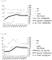
- Figs. 3A and 3B show the water temperature and the state of operation of the cooling fans when the load changes.
- Fig. 3A shows a state of the present embodiment.
- Fig. 3B an example of the conventional inverter control or feed-back control is shown in Fig. 3B .
- the output of the cooling fans rises after the water temperature rises at the timing at which the load is switched from the low load to the high load, so that there is a band of time at which the water temperature is temporarily high.
- an extreme change in the water temperature is prevented from being generated by adopting a feed-forward control in which the approach temperature is changed in advance.
- the second load controlling unit 22 controls to switch from the second approach temperature AP2 to the first approach temperature AP1 before the load of the equipment is switched from the second load to the first load, for example, a predetermined period of time before the load switching timing, so as to allow the absolute value ⁇ TE of the difference to come within the first approach temperature AP1, and subsequently, operation is switched from the second load controlling unit 22 to the first load controlling unit 21.
- the first and/or second load controlling unit 21, 22 makes a setting so that a sum of air flow amounts of the first and second cooling fans 11a, 12a of the first and second cooling towers 11, 12 will be equal to the air flow amount of the first cooling fan 11a of the first cooling tower 11 before the rotational speed exceeds the upper limit threshold value.
- the first and/or second load controlling unit 21, 22 gives an instruction to the first and second motors M1, M2 to set the rotational speed of the fans to control the air flow amounts.
- a set ratio of the air flow amount (rotational speed) of the first cooling fan 11a and the air flow amount (rotational speed) of the second cooling fan 12a is preferably 1 : 1.
- the first and/or second load controlling unit 21, 22 makes a setting so that a sum of amounts of the circulating cooling water W supplied from the first and second supplying units of the first and second cooling towers 11, 12 will be equal to the amount of the circulating cooling water W supplied from the first supplying unit of the first cooling tower 11 before the rotational speed exceeds the upper limit threshold value.
- the first and/or second load controlling unit 21, 22 controls the first and second sluice valves 11b, 12b.
- a set ratio of the amount of the circulating cooling water W supplied from the first supplying unit and the amount of the circulating cooling water W supplied from the second supplying unit is preferably 1 : 1.
- the first and/or second load controlling unit 21, 22 makes a setting so that a sum of air flow amounts of the first, second, and third cooling fans 11a, 12a, and 13a of the first, second, and third cooling towers 11, 12, 13 will be equal to a sum of air flow amounts of the first and second cooling fans 11a, 12a before the rotational speed exceeds the upper limit threshold value.
- the first and/or second load controlling unit 21, 22 gives an instruction to the first, second, and third motors M1, M2, M3 to set the rotational speed of the fans to control the air flow amounts.
- a set ratio of the air flow amount (rotational speed) of the first cooling fan 11a, the air flow amount (rotational speed) of the second cooling fan 12a, and the air flow amount (rotational speed) of the third cooling fan 13a is preferably 1 : 1 : 1.
- the first and/or second load controlling unit 21, 22 makes a setting so that a sum of amounts of the circulating cooling water W supplied from the first, second, and third supplying units will be equal to a sum of amounts of the circulating cooling water W supplied from the first and second supplying units before the rotational speed exceeds the upper limit threshold value.
- the first and/or second load controlling unit 21, 22 controls the first, second, and third sluice valves 11b, 12b, 13b.
- a set ratio of the amount of the circulating cooling water W supplied from the first supplying unit, the amount of the circulating cooling water W supplied from the second supplying unit, and the amount of the circulating cooling water W supplied from the third supplying unit is preferably 1 : 1 : 1.
- the first and/or second load controlling unit 21, 22 makes a setting so that a sum of air flow amounts of the first and second cooling fans 11a, 12a will be equal to a sum of air flow amounts of the first, second, and third cooling fans 11a, 12a, 13a before the rotational speed becomes lower than the lower limit threshold value, and stops the rotation of the third cooling fan 13a.
- the first and/or second load controlling unit 21, 22 gives an instruction to the first and second motors M1, M2 to set the rotational speed of the fans to control the air flow amounts and stops the third motor M3.
- a set ratio of the air flow amount of the first cooling fan 11a and the air flow amount of the second cooling fan 12a is preferably 1 : 1.
- the first and/or second load controlling unit 21, 22 makes a setting so that a sum of amounts of the circulating cooling water W supplied from the first and second supplying units will be equal to a sum of amounts of the circulating cooling water W supplied from the first, second, and third supplying units before the rotational speed becomes lower than the lower limit threshold value, and stops supplying the circulating cooling water W to the third supplying unit.
- the first and/or second load controlling unit 21, 22 gives an instruction to control the first and second automatic on-off sluice valves 11b, 12b and to close the third sluice valve 13b.
- a set ratio of the amount of the circulating cooling water W supplied from the first supplying unit and the amount of the circulating cooling water W supplied from the second supplying unit is preferably 1 : 1.
- the first and/or second load controlling unit 21, 22 makes a setting so that the air flow amount of the first cooling fan 11a will be equal to a sum of air flow amounts of the first and second cooling fans 11a, 12a before the rotational speed becomes lower than the lower limit threshold value, and stops the rotation of the second cooling fan 12a.
- the first and/or second load controlling unit 21, 22 gives an instruction to the first motor M1 to set the rotational speed of the fan to control the air flow amount and stops the second motor M2.
- the first and/or second load controlling unit 21, 22 makes a setting so that the amount of the circulating cooling water W supplied from the first supplying unit will be equal to a sum of amounts of the circulating cooling water W supplied from the first and second supplying units before the rotational speed becomes lower than the lower limit threshold value, and stops supplying the circulating cooling water W to the second supplying unit.
- the first and/or second load controlling unit 21, 22 gives an instruction to control the first automatic on-off sluice valve 11b and to close the second sluice valve 12b.
- Figs. 4A and 4B show stoppage control of the cooling fans.
- Fig. 4A shows a stoppage state of the present embodiment.
- the lower limit threshold value is 33%. It is set that the rotational speeds of the cooling fans are equal to each other. At the time point of 15:00, three cooling fans were operating. However, at the time point of 15:28 at which the rotational speeds of all the cooling fans became lower than the lower limit threshold value of 33%, the third cooling fan stopped, and subsequently, at the time point of 16:07 at which the rotational speeds of the two cooling fans became lower than the lower limit threshold value of 33%, the second cooling fan stopped.
- Fig. 4B an example of the conventional inverter control or feed-back control is shown in Fig. 4B .
- the number of operating cooling fans is changed from three to two or from two to one, one cooling fan is simply stopped without making an output adjustment of the cooling fans, so that the water temperature rises.
- the lower limit threshold value is set to be 33% in the present embodiment, the present invention is not limited to this alone.
- the first and/or second load controlling unit 21, 22 controls the plurality of cooling towers so that the temperature TE1 of the circulating cooling water W will be the set value of the minimum temperature of the circulating cooling water W.
- the "minimum temperature of the cooling water” is set in advance and is stored in a memory of the controlling unit (for example, in the second memory 24), where the minimum temperature can be set to be, for example, 12°C.
- the "predetermined value" may be, for example, the approach temperature.
- the outside air wet-bulb temperature TE0 In winter seasons, there is a time band (for example, during the night) in which the outside air wet-bulb temperature TE0 is considerably lower than this set value of the minimum temperature. In such a case, it is difficult to control the cooling towers with use of the absolute value ⁇ TE of the difference and the approach temperature. For this reason, when the outside air wet-bulb temperature TE0 is lower than the set value of the minimum temperature by the predetermined value or more, the first and/or second load controlling unit 21, 22 controls the first, second, and third cooling fans 11a, 12a, 13a so that the temperature TE1 of the circulating cooling water W will be the set value of the minimum temperature.
- the first and/or second load controlling unit 21, 22 makes a setting so that a sum of air flow amounts of the first and second cooling fans 11a, 12a will be equal to a sum of air flow amounts of the first, second, and third cooling fans 11a, 12a, 13a before the rotational speed becomes lower than the lower limit threshold value, and stops the rotation of the third cooling fan 13a.
- the first and/or second load controlling unit 21, 22 makes a setting so that the air flow amount of the first cooling fan 11a will be equal to a sum of air flow amounts of the first and second cooling fans 11a, 12a before the rotational speed becomes lower than the lower limit threshold value, and stops the rotation of the second cooling fan 12a.
- the first and/or second load controlling unit 21, 22 makes a setting so that a sum of air flow amounts of the first and second cooling fans 11a, 12a of the first and second cooling towers 11, 12 will be equal to the air flow amount of the first cooling fan 11a of the first cooling tower 11 before the rotational speed exceeds the upper limit threshold value.
- the first and/or second load controlling unit 21, 22 makes a setting so that a sum of air flow amounts of the first, second, and third cooling fans 11a, 12a, and 13a of the first, second, and third cooling towers 11, 12, 13 will be equal to a sum of air flow amounts of the first and second cooling fans 11a, 12a before the rotational speed exceeds the upper limit threshold value.
- the first and/or second load controlling unit 21, 22 controls the cooling towers with use of the absolute value ⁇ TE of the difference and the approach temperature as described above. For example, the operation is switched to make a control with use of the absolute value ⁇ TE of the difference and the approach temperature during the day.
- Fig. 5 shows one example of an operation state of the cooling towers in winter seasons.
- the first cooling fan is operating.
- the second cooling fan starts operating at 8 o'clock
- the third cooling fan starts operating when it is past 9 o'clock.
- the third cooling fan stops operating, and subsequently, at 22 o'clock, the second cooling fan stops operating.
- the controlling unit 20 controls the number of operating cooling towers on the basis of the number of operating supplying pumps. For example, when two supplying pumps are operating, it may not be possible to treat the whole amount of the circulating cooling water with use of one cooling tower (or with use of cooling towers the number of which is smaller than that of the supplying pumps).
- One of the reasons therefor is that the cooling water cannot be supplied in an amount larger than or equal to the maximum supply amount (larger than or equal to the flow rate) of the supplying unit of the cooling tower, whereby the cooling water may in some cases overflow from the upper part of the cooling tower.
- the controlling unit 20 makes a control so that the supplying units of at least the same number of cooling towers as that of the supplying pumps are operated.
- a control is made so that the sluice valves of two or more supplying units are let to open even when only one cooling fan is operating.
- a control is made so that, when one more supplying pump starts operating, the sluice valve of the supplying unit of the cooling tower that is in a stoppage state is let to open.
- the sluice valves of three cooling towers are in an opened state when three supplying pumps are operating; the sluice valves of two cooling towers are in an opened state when two supplying pumps are operating; and the sluice valve of one cooling tower is in an opened state when one supplying pump is operating.
- the cooling tower controlling system 1 or the first to third cooling towers 11 to 13 may have a supplying line that replenishes the storage unit 14 with replenishment water.
- a cooling tower controlling method for controlling a plurality of cooling towers that perform temperature control of cooling water used for heat exchange with equipment includes:
- the first load controlling step is adapted to perform a control to switch from the first approach temperature AP1 to the second approach temperature AP2 before a load of the equipment is switched from the first load to the second load, so as to allow the absolute value ⁇ TE of the difference to come within the second approach temperature AP2, and subsequently, transition is made from the first load controlling step to the second load controlling step.
- the second load controlling step is adapted to perform a control to switch from the second approach temperature AP2 to the first approach temperature AP1 before the load of the equipment is switched from the second load to the first load, so as to allow the absolute value ⁇ TE of the difference to come within the first approach temperature AP1, and subsequently, transition is made from the second load controlling step to the first load controlling step.
- the first and/or second load controlling step controls the plurality of cooling towers so that the temperature TE1 of the circulating cooling water W will be the set value of the minimum temperature of the circulating cooling water W.
- the cooling tower controlling method further includes a step of increasing the number of operating cooling towers in which, when the rotational speed of at least one or all of the cooling fans of the cooling towers that are in operation (total number of cooling towers being (i)) exceeds an upper limit threshold value, the step makes a setting so that a sum of air flow amounts of the cooling fans of the cooling towers currently in operation and a newly operated cooling tower (total number of cooling towers being (i+1)) will be equal to a sum of air flow amounts of the cooling fans of the cooling towers that are in operation (total number of cooling towers being (i)) before the rotational speed exceeds the upper limit threshold value, and makes a setting so that a sum of amounts of the circulating cooling water supplied from the supplying units of the cooling towers currently in operation and the newly operated cooling tower (total number of cooling towers being (i+1)) will be equal to a sum of amounts of the circulating cooling water supplied from the supplying units of the cooling towers that are in operation (total number of cooling tower
- the cooling tower controlling method further includes a step of decreasing the number of operating cooling towers in which, when the rotational speed of at least one or all of the cooling fans of the cooling towers that are in operation (total number of cooling towers being (i)) becomes lower than a lower limit threshold value, the step makes a setting so that a sum of air flow amounts of the cooling fans of the cooling towers that will be in operation in a number less by one (total number of cooling towers being (i-1)) than the number of the cooling towers that are currently in operation will be equal to a sum of air flow amounts of the cooling fans of the cooling towers that are in operation (total number of cooling towers being (i)) before the rotational speed becomes lower than the lower limit threshold value, and makes a setting so that a sum of amounts of the circulating cooling water supplied from the supplying units of the cooling towers that will be in operation in a number less by one (total number of cooling towers being (i-1)) than the number of the cooling towers that are currently in operation will be equal
- the controlling unit 20 may receive a measured temperature TE2 from a thermometer 32 that measures the temperature TE2 of the circulating cooling water W flowing through the return pipe L2 and store the temperature TE2 in the first memory 23.
- the order of "first, second, and third” may represent an arbitrary designation and does not absolutely specify one or all of these.
- the order of "first to third" in the first load period may not completely coincide with the order of "first to third” in the second load period, so that, for example, the order of "first” in the first load period may correspond to the order of "second" or "third” in the second load period.
Landscapes
- Engineering & Computer Science (AREA)
- Mechanical Engineering (AREA)
- General Engineering & Computer Science (AREA)
- Physics & Mathematics (AREA)
- Thermal Sciences (AREA)
- Air Conditioning Control Device (AREA)
- Other Air-Conditioning Systems (AREA)
- Control Of Temperature (AREA)
Claims (7)
- Système de commande de tours de refroidissement pour commander une pluralité de tours de refroidissement (11, 12, 13) qui effectuent une commande de température de l'eau de refroidissement utilisée pour un échange de chaleur avec un équipement, comprenant :la pluralité de tours de refroidissement ayant chacune un ventilateur de refroidissement (11a, 12a, 13a), une unité d'entraînement en rotation (M1, M2, M3) qui est une source d'entraînement pour faire tourner le ventilateur de refroidissement, une unité d'alimentation (L31, 11b, 11c, L32, 12b, 12c, L33, 13b, 13c) qui fournit de l'eau de refroidissement circulatoire (W) qui est passée à travers une unité d'échange de chaleur (50) de l'équipement à la tour de refroidissement, et une unité de stockage (14) qui stocke l'eau de refroidissement circulatoire qui a été refroidie par soufflage d'air par le ventilateur de refroidissement ;une pluralité de pompes (P1, P2, P3) qui envoient l'eau de refroidissement circulatoire de l'unité de stockage à l'unité d'échange de chaleur de l'équipement ;une conduite de circulation ayant un tuyau (L1) qui se raccorde respectivement entre l'unité de stockage et les pompes, entre les pompes et l'unité d'échange de chaleur de l'équipement et entre l'unité d'échange de chaleur et les unités d'alimentation des tours de refroidissement de manière à permettre à l'eau de refroidissement circulatoire de s'écouler à travers celles-ci ;une unité de mesure de température (31) qui mesure une température de l'eau de refroidissement circulatoire dans la conduite de circulation dans une position en amont de l'unité d'échange de chaleur et en aval de l'unité de stockage ou une température de l'eau de refroidissement circulatoire dans l'unité de stockage ou dans les pompes ;une première unité de commande de charge (21) qui commande une vitesse de rotation des ventilateurs de refroidissement avec des unités d'entraînement en rotation respectives de sorte qu'une valeur absolue ΔTE d'une différence entre la température TE1 mesurée dans l'unité de mesure de température et une température au thermomètre mouillé d'air extérieur TE0 arrive dans une première température d'approche AP1, qui correspond à une première charge, dans une première période de charge de l'équipement; etune seconde unité de commande de charge (22) qui commande la vitesse de rotation des ventilateurs de refroidissement avec des unités d'entraînement en rotation respectives de sorte que la valeur absolue ΔTE de la différence entre la température TE1 mesurée dans l'unité de mesure de température et la température au thermomètre mouillé d'air extérieur TE0 arrive dans une seconde température d'approche AP2, qui correspond à une seconde charge supérieure à la première charge et présente une valeur inférieure à la première température d'approche AP1, dans la seconde période de charge de l'équipement.
- Système de commande de tours de refroidissement selon la revendication 1, dans lequel :la première unité de commande de charge (21) commande de commuter de la première température d'approche AP1 à la seconde température d'approche AP2 avant qu'une charge de l'équipement ne soit commutée de la première charge à la seconde charge afin de permettre à la valeur absolue ΔTE de la différence d'arriver dans la seconde température d'approche AP2 et, ensuite, l'opération est commutée de la première unité de commande de charge à la seconde unité de commande de charge et/oula seconde unité de commande de charge (22) commande de commuter de la seconde température d'approche AP2 à la première température d'approche AP1 avant que la charge de l'équipement ne soit commutée de la seconde charge à la première charge afin de permettre à la valeur absolue ΔTE de la différence d'arriver dans la première température d'approche AP1 et, ensuite, l'opération est commutée de la seconde unité de commande de charge à la première unité de commande de charge.
- Système de commande de tours de refroidissement selon la revendication 1 ou 2, dans lequel, lorsque la vitesse de rotation d'au moins l'un ou de la totalité des ventilateurs de refroidissement (11a, 12a, 13a) des tours de refroidissement (11, 12, 13) qui sont en service dépasse une valeur de seuil limite supérieure, la première unité de commande de charge et/ou la seconde unité de commande de charge effectue(nt) un réglage de sorte que la somme des quantités d'écoulement d'air des ventilateurs de refroidissement des tours de refroidissement couramment en service et d'une tour de refroidissement récemment mise en marche soit égale à une somme des quantités d'écoulement d'air des ventilateurs de refroidissement des tours de refroidissement qui sont en service avant que la vitesse de rotation ne dépasse la valeur de seuil limite supérieure, et effectue un réglage de sorte qu'une somme des quantités de l'eau de refroidissement circulatoire fournie par les unités d'alimentation des tours de refroidissement couramment en service et de la tour de refroidissement récemment mise en marche soit égale à une somme des quantités d'eau de refroidissement circulatoire fournie par les unités d'alimentation des tours de refroidissement qui sont en service avant que la vitesse de rotation ne dépasse la valeur de seuil limite supérieure.
- Système de commande de tours de refroidissement selon l'une quelconque des revendications 1 à 3, dans lequel, lorsque la vitesse de rotation d'au moins l'un ou de la totalité des ventilateurs de refroidissement (11a, 12a, 13a) des tours de refroidissement (11, 12, 13) qui sont en service devient inférieure à une valeur de seuil limite inférieure, la première unité de commande de charge et/ou la seconde unité de commande de charge effectue(nt) un réglage de sorte qu'une somme des quantités d'écoulement d'air des ventilateurs de refroidissement des tours de refroidissement qui sont en service en nombre inférieur à un du nombre des tours de refroidissement qui sont couramment en service soit égale à une somme de quantités d'écoulement d'air des ventilateurs de refroidissement des tours de refroidissement qui sont en service avant que la vitesse de rotation ne devienne inférieure à la valeur de seuil limite inférieure, et effectue un réglage de sorte qu'une somme des quantités de l'eau de refroidissement circulatoire fournie par les unités d'alimentation des tours de refroidissement qui sont en service en nombre inférieur à un au nombre des tours de refroidissement qui sont couramment en service soit égale à une somme de quantités d'eau de refroidissement circulatoire fournie par les unités d'alimentation des tours de refroidissement qui sont en service avant que la vitesse de rotation ne devienne inférieure à la valeur de seuil limite inférieure, et arrête la rotation du ventilateur de refroidissement de l'une des tours de refroidissement et arrête l'alimentation en eau de refroidissement circulatoire de celles-ci.
- Système de commande de tours de refroidissement selon l'une quelconque des revendications 1 à 4, dans lequel, lorsque la température au thermomètre mouillé d'air extérieur TE0 est inférieure à une valeur de consigne d'une température minimale de l'eau de refroidissement circulatoire d'une valeur prédéterminée ou plus, la première unité de commande de charge et/ou la seconde unité de commande de charge commande(nt) la pluralité de tours de refroidissement de sorte que la température TE1 de l'eau de refroidissement circulatoire (W) soit la valeur de consigne de la température minimale de l'eau de refroidissement circulatoire.
- Procédé de commande de tours de refroidissement pour commander une pluralité de tours de refroidissement (11, 12, 13) d'un système de commande de tours de refroidissement selon la revendication 1, chaque tour de refroidissement ayant un ventilateur de refroidissement (11a, 12a, 13a) qui effectue une commande de température de l'eau de refroidissement (W) utilisée pour un échange de chaleur avec l'équipement, comprenant :une première étape de commande de charge qui commande une vitesse de rotation des ventilateurs de refroidissement de sorte qu'une valeur absolue ΔTE d'une différence entre une température TE1 d'eau de refroidissement circulatoire dans une position entre une unité d'échange de chaleur de l'équipement et une unité de stockage des tours de refroidissement et une température au thermomètre mouillé d'air externe TE0 arrive dans une première température d'approche AP1, qui correspond à la première charge, dans une première période de charge de l'équipement ; etune seconde étape de commande de charge qui commande la vitesse de rotation des ventilateurs de refroidissement de sorte que la valeur absolue ΔTE de la différence entre la température TE1 de l'eau de refroidissement circulatoire dans la position comprise entre l'unité d'échange de chaleur de l'équipement et l'unité de stockage des tours de refroidissement et la température au thermomètre mouillé d'air externe TE0 arrive dans une seconde température d'approche AP2, qui correspond à une seconde charge supérieure à la première charge et a une valeur inférieure à la première température d'approche AP1, dans la seconde période de charge de l'appareil.
- Procédé de commande de tours de refroidissement selon la revendication 6, dans lequel :la première étape de commande de charge est à même d'effectuer une commande pour commuter de la première température d'approche AP1 à la seconde température d'approche AP2 avant qu'une charge de l'équipement ne soit commutée de la première charge à la seconde charge afin de permettre à la valeur absolue ΔTE de la différence d'arriver dans la seconde température d'approche AP2 et, ensuite, une transition est effectuée de la première étape de commande de charge à la seconde étape de commande de charge et/oula seconde étape de commande de charge est à même d'effectuer une commande pour commuter de la seconde température d'approche AP2 à la première température d'approche AP1 avant que la charge de l'équipement ne soit commutée de la seconde charge à la première charge afin de permettre à la valeur absolue ΔTE de la différence d'arriver dans la première température d'approche AP1 et, ensuite, la transition est effectuée de la seconde étape de commande de charge à la première étape de commande de charge.
Applications Claiming Priority (2)
| Application Number | Priority Date | Filing Date | Title |
|---|---|---|---|
| JP2015197750A JP6408972B2 (ja) | 2015-10-05 | 2015-10-05 | 冷却塔制御システムおよび冷却塔制御方法 |
| PCT/EP2016/072692 WO2017060103A1 (fr) | 2015-10-05 | 2016-09-23 | Système et procédé de commande d'une tour de refroidissement |
Publications (2)
| Publication Number | Publication Date |
|---|---|
| EP3380802A1 EP3380802A1 (fr) | 2018-10-03 |
| EP3380802B1 true EP3380802B1 (fr) | 2019-11-06 |
Family
ID=57103981
Family Applications (1)
| Application Number | Title | Priority Date | Filing Date |
|---|---|---|---|
| EP16777941.2A Active EP3380802B1 (fr) | 2015-10-05 | 2016-09-23 | Système et procédé de commande d'une tour de refroidissement |
Country Status (6)
| Country | Link |
|---|---|
| US (1) | US10712106B2 (fr) |
| EP (1) | EP3380802B1 (fr) |
| JP (1) | JP6408972B2 (fr) |
| CN (1) | CN108291789B (fr) |
| EA (1) | EA035196B1 (fr) |
| WO (1) | WO2017060103A1 (fr) |
Families Citing this family (15)
| Publication number | Priority date | Publication date | Assignee | Title |
|---|---|---|---|---|
| CN109205761A (zh) * | 2017-06-30 | 2019-01-15 | 上海轻工业研究所有限公司 | 臭氧处理的循环冷却水系统及臭氧注入量控制装置和方法 |
| CN111043818A (zh) * | 2018-10-11 | 2020-04-21 | 领凡新能源科技(北京)有限公司 | 冷却水循环控制方法及系统 |
| JP7149800B2 (ja) * | 2018-10-15 | 2022-10-07 | 東京瓦斯株式会社 | 冷却塔システム |
| CN109539433B (zh) * | 2018-10-15 | 2022-03-25 | 平安科技(深圳)有限公司 | 冷却水串联系统、回路控制方法和存储介质 |
| CN109539432B (zh) * | 2018-10-15 | 2021-09-28 | 平安科技(深圳)有限公司 | 空调冷却水循环系统和空调冷却水回路控制方法 |
| JP6887537B2 (ja) * | 2019-02-15 | 2021-06-16 | 株式会社中部プラントサービス | 冷却水系統設備及びその制御装置 |
| CN110398034B (zh) * | 2019-07-15 | 2021-05-04 | 上海美控智慧建筑有限公司 | 空调的冷却塔控制方法、系统及空调 |
| CN112705011B (zh) * | 2019-10-25 | 2022-02-18 | 中冶长天国际工程有限责任公司 | 解析塔的热风风机控制方法及装置 |
| CN112284182A (zh) * | 2020-10-28 | 2021-01-29 | 上海能誉科技股份有限公司 | 一种冷却塔的节能控制系统及方法 |
| CN112665443B (zh) * | 2020-12-25 | 2022-11-25 | 北京首都机场动力能源有限公司 | 一种用于中央空调系统的冷却塔控制方法和系统 |
| CN115111958A (zh) * | 2022-06-10 | 2022-09-27 | 珠海格力电器股份有限公司 | 冷却塔台数自动控制方法、控制装置及制冷设备 |
| CN115289896B (zh) * | 2022-08-03 | 2025-05-23 | 北京京能恒星能源科技有限公司 | 一种能源站用冷却塔组控制方法及装置 |
| CN115899894A (zh) * | 2022-12-19 | 2023-04-04 | 深圳市英维克科技股份有限公司 | 复合蒸发冷却机组及其控制方法、可读存储介质 |
| CN118816368B (zh) * | 2024-08-28 | 2025-07-18 | 南通百源制冷设备有限公司 | 一种冷风机能耗智能控制方法及系统 |
| CN119245191B (zh) * | 2024-12-02 | 2025-03-07 | 深圳前海中碳综合能源科技有限公司 | 中央空调系统的冷却塔寻优控制方法、装置、终端及介质 |
Family Cites Families (19)
| Publication number | Priority date | Publication date | Assignee | Title |
|---|---|---|---|---|
| JPS532936A (en) * | 1976-06-28 | 1978-01-12 | Canada Square Management Ltd | Method of and apparatus for controlling room temperature of building |
| JPS5467251A (en) * | 1977-11-08 | 1979-05-30 | Ishikawajima Harima Heavy Ind Co Ltd | Water cooling towersigma automatic water temperature control method |
| JPS5565884A (en) * | 1978-11-14 | 1980-05-17 | Ishikawajima Harima Heavy Ind Co Ltd | Conveying water temperature control method for cooling water tower |
| JPS5963497A (ja) * | 1982-10-04 | 1984-04-11 | Mitsubishi Electric Corp | 冷却装置 |
| US4474027A (en) * | 1983-01-31 | 1984-10-02 | The Babcock & Wilcox Company | Optimum control of cooling tower water temperature by function blocks |
| JPS59157495A (ja) * | 1983-02-24 | 1984-09-06 | Ishikawajima Harima Heavy Ind Co Ltd | 冷水塔の電動機の給電制御方法 |
| US6446448B1 (en) * | 2001-06-26 | 2002-09-10 | Chi-Yi Wang | Cooling tower for automatically adjusting flow rates of cooling water and cooling air with variations of a load |
| JP3813575B2 (ja) * | 2002-12-09 | 2006-08-23 | トヨタ自動車株式会社 | 開放式冷却塔及び開放式冷却塔の凍結防止方法 |
| JP2006207929A (ja) * | 2005-01-28 | 2006-08-10 | Daikin Ind Ltd | 空調システムの最適運転制御システムおよび最適運転制御方法 |
| JP4505436B2 (ja) * | 2006-06-19 | 2010-07-21 | 東洋熱工業株式会社 | 冷却塔群の省エネルギー運転方法及びこれに用いる冷却塔群 |
| CN201003930Y (zh) * | 2006-08-31 | 2008-01-09 | 王吉一 | 一种冷却水塔 |
| JP5500615B2 (ja) * | 2008-04-10 | 2014-05-21 | 川重冷熱工業株式会社 | 冷凍機冷却水温度安定化による省エネルギー制御運転方法 |
| JP5363139B2 (ja) * | 2009-02-25 | 2013-12-11 | アズビル株式会社 | 冷却塔ファン制御装置および方法 |
| JP5404132B2 (ja) | 2009-03-30 | 2014-01-29 | 三菱重工業株式会社 | 熱源システムおよびその制御方法 |
| JP5513984B2 (ja) * | 2010-05-21 | 2014-06-04 | 株式会社日立製作所 | 冷水製造設備および冷水製造方法 |
| JP5890697B2 (ja) * | 2012-01-31 | 2016-03-22 | アズビル株式会社 | 冷却塔ファン制御装置および方法 |
| JP6090904B2 (ja) * | 2012-02-29 | 2017-03-08 | 三菱重工業株式会社 | 冷却塔制御装置、冷却塔制御方法、及び熱源システム |
| CN102840725B (zh) * | 2012-09-27 | 2014-07-16 | 山东中瑞新能源科技有限公司 | 地埋管及冷却塔地源热泵复合系统的控制系统及方法 |
| JP5984703B2 (ja) * | 2013-01-31 | 2016-09-06 | 三菱重工業株式会社 | 熱源システム及び冷却水供給装置の制御装置並びに制御方法 |
-
2015
- 2015-10-05 JP JP2015197750A patent/JP6408972B2/ja active Active
-
2016
- 2016-09-23 CN CN201680067181.7A patent/CN108291789B/zh active Active
- 2016-09-23 EA EA201890786A patent/EA035196B1/ru not_active IP Right Cessation
- 2016-09-23 EP EP16777941.2A patent/EP3380802B1/fr active Active
- 2016-09-23 WO PCT/EP2016/072692 patent/WO2017060103A1/fr not_active Ceased
- 2016-09-23 US US15/766,310 patent/US10712106B2/en active Active
Non-Patent Citations (1)
| Title |
|---|
| None * |
Also Published As
| Publication number | Publication date |
|---|---|
| JP6408972B2 (ja) | 2018-10-17 |
| WO2017060103A1 (fr) | 2017-04-13 |
| EP3380802A1 (fr) | 2018-10-03 |
| EA201890786A1 (ru) | 2018-08-31 |
| US10712106B2 (en) | 2020-07-14 |
| EA035196B1 (ru) | 2020-05-14 |
| US20180299214A1 (en) | 2018-10-18 |
| CN108291789B (zh) | 2019-12-13 |
| CN108291789A (zh) | 2018-07-17 |
| JP2017072269A (ja) | 2017-04-13 |
Similar Documents
| Publication | Publication Date | Title |
|---|---|---|
| US10712106B2 (en) | Cooling tower controlling system and cooling tower controlling method | |
| JP2017072269A5 (fr) | ||
| CN112449549B (zh) | 冷却循环装置、控制方法及变流器 | |
| JP5261170B2 (ja) | 熱負荷処理システム、及び、熱源システム | |
| JP5513984B2 (ja) | 冷水製造設備および冷水製造方法 | |
| JP4594276B2 (ja) | 冷温熱源機の冷温水制御方法及びこれに用いる空調システム | |
| JP5515166B2 (ja) | 熱源システム | |
| JP5227247B2 (ja) | 熱源システム運転方法及び熱源システム | |
| US20220316733A1 (en) | Multi-stage thermal management systems and methods | |
| CN104236020A (zh) | 一种空调系统的控制方法及装置 | |
| JP5489046B2 (ja) | 熱源設備制御システム | |
| JP6029363B2 (ja) | 熱源システム | |
| CN115860445A (zh) | 铀浓缩制冷机组与闭式冷却塔多层级协同调度方法 | |
| JP5476835B2 (ja) | 空調システム | |
| JP5944957B2 (ja) | 熱源システム制御方法及びその装置 | |
| JP2020041767A (ja) | 制御装置、熱源システム、ファン起動台数決定方法及びプログラム | |
| CN120120700A (zh) | 一种冷冻水系统运行控制方法、冷冻水系统和存储介质 | |
| CN119416546A (zh) | 太阳能地源热泵系统的仿真方法、装置、设备及介质 | |
| CN110701839B (zh) | 冷机站管理装置和方法、计算机存储介质以及冷机站 | |
| CN115013952B (zh) | 一种空调系统的控制方法和装置 | |
| JP2018004190A (ja) | 空調システム | |
| JP3854586B2 (ja) | 熱源システムと当該熱源システムの制御方法及び熱源と当該熱源の制御方法 | |
| CN118912658B (zh) | 一种三级泵变流量自动控制方法 | |
| CN204787075U (zh) | 中央空调节能控制系统 | |
| CN119374192B (zh) | 基于空调的温度控制方法、装置及电子设备 |
Legal Events
| Date | Code | Title | Description |
|---|---|---|---|
| STAA | Information on the status of an ep patent application or granted ep patent |
Free format text: STATUS: THE INTERNATIONAL PUBLICATION HAS BEEN MADE |
|
| PUAI | Public reference made under article 153(3) epc to a published international application that has entered the european phase |
Free format text: ORIGINAL CODE: 0009012 |
|
| STAA | Information on the status of an ep patent application or granted ep patent |
Free format text: STATUS: REQUEST FOR EXAMINATION WAS MADE |
|
| 17P | Request for examination filed |
Effective date: 20180822 |
|
| AK | Designated contracting states |
Kind code of ref document: A1 Designated state(s): AL AT BE BG CH CY CZ DE DK EE ES FI FR GB GR HR HU IE IS IT LI LT LU LV MC MK MT NL NO PL PT RO RS SE SI SK SM TR |
|
| AX | Request for extension of the european patent |
Extension state: BA ME |
|
| DAV | Request for validation of the european patent (deleted) | ||
| DAX | Request for extension of the european patent (deleted) | ||
| GRAP | Despatch of communication of intention to grant a patent |
Free format text: ORIGINAL CODE: EPIDOSNIGR1 |
|
| STAA | Information on the status of an ep patent application or granted ep patent |
Free format text: STATUS: GRANT OF PATENT IS INTENDED |
|
| INTG | Intention to grant announced |
Effective date: 20190613 |
|
| GRAS | Grant fee paid |
Free format text: ORIGINAL CODE: EPIDOSNIGR3 |
|
| GRAA | (expected) grant |
Free format text: ORIGINAL CODE: 0009210 |
|
| STAA | Information on the status of an ep patent application or granted ep patent |
Free format text: STATUS: THE PATENT HAS BEEN GRANTED |
|
| AK | Designated contracting states |
Kind code of ref document: B1 Designated state(s): AL AT BE BG CH CY CZ DE DK EE ES FI FR GB GR HR HU IE IS IT LI LT LU LV MC MK MT NL NO PL PT RO RS SE SI SK SM TR |
|
| REG | Reference to a national code |
Ref country code: GB Ref legal event code: FG4D |
|
| REG | Reference to a national code |
Ref country code: CH Ref legal event code: EP Ref country code: AT Ref legal event code: REF Ref document number: 1199322 Country of ref document: AT Kind code of ref document: T Effective date: 20191115 |
|
| REG | Reference to a national code |
Ref country code: DE Ref legal event code: R096 Ref document number: 602016023917 Country of ref document: DE |
|
| REG | Reference to a national code |
Ref country code: IE Ref legal event code: FG4D |
|
| REG | Reference to a national code |
Ref country code: NL Ref legal event code: FP |
|
| REG | Reference to a national code |
Ref country code: LT Ref legal event code: MG4D |
|
| PG25 | Lapsed in a contracting state [announced via postgrant information from national office to epo] |
Ref country code: FI Free format text: LAPSE BECAUSE OF FAILURE TO SUBMIT A TRANSLATION OF THE DESCRIPTION OR TO PAY THE FEE WITHIN THE PRESCRIBED TIME-LIMIT Effective date: 20191106 Ref country code: BG Free format text: LAPSE BECAUSE OF FAILURE TO SUBMIT A TRANSLATION OF THE DESCRIPTION OR TO PAY THE FEE WITHIN THE PRESCRIBED TIME-LIMIT Effective date: 20200206 Ref country code: GR Free format text: LAPSE BECAUSE OF FAILURE TO SUBMIT A TRANSLATION OF THE DESCRIPTION OR TO PAY THE FEE WITHIN THE PRESCRIBED TIME-LIMIT Effective date: 20200207 Ref country code: LT Free format text: LAPSE BECAUSE OF FAILURE TO SUBMIT A TRANSLATION OF THE DESCRIPTION OR TO PAY THE FEE WITHIN THE PRESCRIBED TIME-LIMIT Effective date: 20191106 Ref country code: PL Free format text: LAPSE BECAUSE OF FAILURE TO SUBMIT A TRANSLATION OF THE DESCRIPTION OR TO PAY THE FEE WITHIN THE PRESCRIBED TIME-LIMIT Effective date: 20191106 Ref country code: LV Free format text: LAPSE BECAUSE OF FAILURE TO SUBMIT A TRANSLATION OF THE DESCRIPTION OR TO PAY THE FEE WITHIN THE PRESCRIBED TIME-LIMIT Effective date: 20191106 Ref country code: SE Free format text: LAPSE BECAUSE OF FAILURE TO SUBMIT A TRANSLATION OF THE DESCRIPTION OR TO PAY THE FEE WITHIN THE PRESCRIBED TIME-LIMIT Effective date: 20191106 Ref country code: NO Free format text: LAPSE BECAUSE OF FAILURE TO SUBMIT A TRANSLATION OF THE DESCRIPTION OR TO PAY THE FEE WITHIN THE PRESCRIBED TIME-LIMIT Effective date: 20200206 Ref country code: PT Free format text: LAPSE BECAUSE OF FAILURE TO SUBMIT A TRANSLATION OF THE DESCRIPTION OR TO PAY THE FEE WITHIN THE PRESCRIBED TIME-LIMIT Effective date: 20200306 |
|
| PG25 | Lapsed in a contracting state [announced via postgrant information from national office to epo] |
Ref country code: IS Free format text: LAPSE BECAUSE OF FAILURE TO SUBMIT A TRANSLATION OF THE DESCRIPTION OR TO PAY THE FEE WITHIN THE PRESCRIBED TIME-LIMIT Effective date: 20200306 Ref country code: RS Free format text: LAPSE BECAUSE OF FAILURE TO SUBMIT A TRANSLATION OF THE DESCRIPTION OR TO PAY THE FEE WITHIN THE PRESCRIBED TIME-LIMIT Effective date: 20191106 Ref country code: HR Free format text: LAPSE BECAUSE OF FAILURE TO SUBMIT A TRANSLATION OF THE DESCRIPTION OR TO PAY THE FEE WITHIN THE PRESCRIBED TIME-LIMIT Effective date: 20191106 |
|
| PG25 | Lapsed in a contracting state [announced via postgrant information from national office to epo] |
Ref country code: AL Free format text: LAPSE BECAUSE OF FAILURE TO SUBMIT A TRANSLATION OF THE DESCRIPTION OR TO PAY THE FEE WITHIN THE PRESCRIBED TIME-LIMIT Effective date: 20191106 |
|
| PG25 | Lapsed in a contracting state [announced via postgrant information from national office to epo] |
Ref country code: ES Free format text: LAPSE BECAUSE OF FAILURE TO SUBMIT A TRANSLATION OF THE DESCRIPTION OR TO PAY THE FEE WITHIN THE PRESCRIBED TIME-LIMIT Effective date: 20191106 Ref country code: EE Free format text: LAPSE BECAUSE OF FAILURE TO SUBMIT A TRANSLATION OF THE DESCRIPTION OR TO PAY THE FEE WITHIN THE PRESCRIBED TIME-LIMIT Effective date: 20191106 Ref country code: DK Free format text: LAPSE BECAUSE OF FAILURE TO SUBMIT A TRANSLATION OF THE DESCRIPTION OR TO PAY THE FEE WITHIN THE PRESCRIBED TIME-LIMIT Effective date: 20191106 Ref country code: CZ Free format text: LAPSE BECAUSE OF FAILURE TO SUBMIT A TRANSLATION OF THE DESCRIPTION OR TO PAY THE FEE WITHIN THE PRESCRIBED TIME-LIMIT Effective date: 20191106 Ref country code: RO Free format text: LAPSE BECAUSE OF FAILURE TO SUBMIT A TRANSLATION OF THE DESCRIPTION OR TO PAY THE FEE WITHIN THE PRESCRIBED TIME-LIMIT Effective date: 20191106 |
|
| REG | Reference to a national code |
Ref country code: DE Ref legal event code: R097 Ref document number: 602016023917 Country of ref document: DE |
|
| REG | Reference to a national code |
Ref country code: AT Ref legal event code: MK05 Ref document number: 1199322 Country of ref document: AT Kind code of ref document: T Effective date: 20191106 |
|
| PG25 | Lapsed in a contracting state [announced via postgrant information from national office to epo] |
Ref country code: SM Free format text: LAPSE BECAUSE OF FAILURE TO SUBMIT A TRANSLATION OF THE DESCRIPTION OR TO PAY THE FEE WITHIN THE PRESCRIBED TIME-LIMIT Effective date: 20191106 Ref country code: SK Free format text: LAPSE BECAUSE OF FAILURE TO SUBMIT A TRANSLATION OF THE DESCRIPTION OR TO PAY THE FEE WITHIN THE PRESCRIBED TIME-LIMIT Effective date: 20191106 |
|
| PLBE | No opposition filed within time limit |
Free format text: ORIGINAL CODE: 0009261 |
|
| STAA | Information on the status of an ep patent application or granted ep patent |
Free format text: STATUS: NO OPPOSITION FILED WITHIN TIME LIMIT |
|
| 26N | No opposition filed |
Effective date: 20200807 |
|
| PG25 | Lapsed in a contracting state [announced via postgrant information from national office to epo] |
Ref country code: AT Free format text: LAPSE BECAUSE OF FAILURE TO SUBMIT A TRANSLATION OF THE DESCRIPTION OR TO PAY THE FEE WITHIN THE PRESCRIBED TIME-LIMIT Effective date: 20191106 Ref country code: SI Free format text: LAPSE BECAUSE OF FAILURE TO SUBMIT A TRANSLATION OF THE DESCRIPTION OR TO PAY THE FEE WITHIN THE PRESCRIBED TIME-LIMIT Effective date: 20191106 |
|
| PG25 | Lapsed in a contracting state [announced via postgrant information from national office to epo] |
Ref country code: IT Free format text: LAPSE BECAUSE OF FAILURE TO SUBMIT A TRANSLATION OF THE DESCRIPTION OR TO PAY THE FEE WITHIN THE PRESCRIBED TIME-LIMIT Effective date: 20191106 |
|
| REG | Reference to a national code |
Ref country code: CH Ref legal event code: PL |
|
| PG25 | Lapsed in a contracting state [announced via postgrant information from national office to epo] |
Ref country code: LU Free format text: LAPSE BECAUSE OF NON-PAYMENT OF DUE FEES Effective date: 20200923 |
|
| PG25 | Lapsed in a contracting state [announced via postgrant information from national office to epo] |
Ref country code: CH Free format text: LAPSE BECAUSE OF NON-PAYMENT OF DUE FEES Effective date: 20200930 Ref country code: IE Free format text: LAPSE BECAUSE OF NON-PAYMENT OF DUE FEES Effective date: 20200923 Ref country code: LI Free format text: LAPSE BECAUSE OF NON-PAYMENT OF DUE FEES Effective date: 20200930 |
|
| PG25 | Lapsed in a contracting state [announced via postgrant information from national office to epo] |
Ref country code: TR Free format text: LAPSE BECAUSE OF FAILURE TO SUBMIT A TRANSLATION OF THE DESCRIPTION OR TO PAY THE FEE WITHIN THE PRESCRIBED TIME-LIMIT Effective date: 20191106 Ref country code: MT Free format text: LAPSE BECAUSE OF FAILURE TO SUBMIT A TRANSLATION OF THE DESCRIPTION OR TO PAY THE FEE WITHIN THE PRESCRIBED TIME-LIMIT Effective date: 20191106 Ref country code: CY Free format text: LAPSE BECAUSE OF FAILURE TO SUBMIT A TRANSLATION OF THE DESCRIPTION OR TO PAY THE FEE WITHIN THE PRESCRIBED TIME-LIMIT Effective date: 20191106 |
|
| PG25 | Lapsed in a contracting state [announced via postgrant information from national office to epo] |
Ref country code: MK Free format text: LAPSE BECAUSE OF FAILURE TO SUBMIT A TRANSLATION OF THE DESCRIPTION OR TO PAY THE FEE WITHIN THE PRESCRIBED TIME-LIMIT Effective date: 20191106 Ref country code: MC Free format text: LAPSE BECAUSE OF FAILURE TO SUBMIT A TRANSLATION OF THE DESCRIPTION OR TO PAY THE FEE WITHIN THE PRESCRIBED TIME-LIMIT Effective date: 20191106 |
|
| P01 | Opt-out of the competence of the unified patent court (upc) registered |
Effective date: 20230523 |
|
| PGFP | Annual fee paid to national office [announced via postgrant information from national office to epo] |
Ref country code: DE Payment date: 20240918 Year of fee payment: 9 |
|
| PGFP | Annual fee paid to national office [announced via postgrant information from national office to epo] |
Ref country code: GB Payment date: 20240920 Year of fee payment: 9 |
|
| PGFP | Annual fee paid to national office [announced via postgrant information from national office to epo] |
Ref country code: BE Payment date: 20240918 Year of fee payment: 9 |
|
| PGFP | Annual fee paid to national office [announced via postgrant information from national office to epo] |
Ref country code: FR Payment date: 20240925 Year of fee payment: 9 |
|
| PGFP | Annual fee paid to national office [announced via postgrant information from national office to epo] |
Ref country code: NL Payment date: 20240918 Year of fee payment: 9 |
|
| REG | Reference to a national code |
Ref country code: NL Ref legal event code: MM Effective date: 20251001 |