EP3380825B1 - Dispositif et procédé pour analyser des objets biologiques par spectroscopie raman - Google Patents
Dispositif et procédé pour analyser des objets biologiques par spectroscopie raman Download PDFInfo
- Publication number
- EP3380825B1 EP3380825B1 EP16819271.4A EP16819271A EP3380825B1 EP 3380825 B1 EP3380825 B1 EP 3380825B1 EP 16819271 A EP16819271 A EP 16819271A EP 3380825 B1 EP3380825 B1 EP 3380825B1
- Authority
- EP
- European Patent Office
- Prior art keywords
- biological
- raman
- substance
- biological objects
- raman spectrum
- Prior art date
- Legal status (The legal status is an assumption and is not a legal conclusion. Google has not performed a legal analysis and makes no representation as to the accuracy of the status listed.)
- Active
Links
Images





Classifications
-
- G—PHYSICS
- G01—MEASURING; TESTING
- G01N—INVESTIGATING OR ANALYSING MATERIALS BY DETERMINING THEIR CHEMICAL OR PHYSICAL PROPERTIES
- G01N21/00—Investigating or analysing materials by the use of optical means, i.e. using sub-millimetre waves, infrared, visible or ultraviolet light
- G01N21/62—Systems in which the material investigated is excited whereby it emits light or causes a change in wavelength of the incident light
- G01N21/63—Systems in which the material investigated is excited whereby it emits light or causes a change in wavelength of the incident light optically excited
- G01N21/65—Raman scattering
-
- G—PHYSICS
- G01—MEASURING; TESTING
- G01N—INVESTIGATING OR ANALYSING MATERIALS BY DETERMINING THEIR CHEMICAL OR PHYSICAL PROPERTIES
- G01N21/00—Investigating or analysing materials by the use of optical means, i.e. using sub-millimetre waves, infrared, visible or ultraviolet light
- G01N21/01—Arrangements or apparatus for facilitating the optical investigation
- G01N21/03—Cuvette constructions
-
- G—PHYSICS
- G01—MEASURING; TESTING
- G01N—INVESTIGATING OR ANALYSING MATERIALS BY DETERMINING THEIR CHEMICAL OR PHYSICAL PROPERTIES
- G01N33/00—Investigating or analysing materials by specific methods not covered by groups G01N1/00 - G01N31/00
- G01N33/48—Biological material, e.g. blood, urine; Haemocytometers
- G01N33/50—Chemical analysis of biological material, e.g. blood, urine; Testing involving biospecific ligand binding methods; Immunological testing
- G01N33/5005—Chemical analysis of biological material, e.g. blood, urine; Testing involving biospecific ligand binding methods; Immunological testing involving human or animal cells
- G01N33/5008—Chemical analysis of biological material, e.g. blood, urine; Testing involving biospecific ligand binding methods; Immunological testing involving human or animal cells for testing or evaluating the effect of chemical or biological compounds, e.g. drugs, cosmetics
- G01N33/5014—Chemical analysis of biological material, e.g. blood, urine; Testing involving biospecific ligand binding methods; Immunological testing involving human or animal cells for testing or evaluating the effect of chemical or biological compounds, e.g. drugs, cosmetics for testing toxicity
-
- G—PHYSICS
- G01—MEASURING; TESTING
- G01N—INVESTIGATING OR ANALYSING MATERIALS BY DETERMINING THEIR CHEMICAL OR PHYSICAL PROPERTIES
- G01N33/00—Investigating or analysing materials by specific methods not covered by groups G01N1/00 - G01N31/00
- G01N33/48—Biological material, e.g. blood, urine; Haemocytometers
- G01N33/50—Chemical analysis of biological material, e.g. blood, urine; Testing involving biospecific ligand binding methods; Immunological testing
- G01N33/5005—Chemical analysis of biological material, e.g. blood, urine; Testing involving biospecific ligand binding methods; Immunological testing involving human or animal cells
- G01N33/5094—Chemical analysis of biological material, e.g. blood, urine; Testing involving biospecific ligand binding methods; Immunological testing involving human or animal cells for blood cell populations
-
- G—PHYSICS
- G21—NUCLEAR PHYSICS; NUCLEAR ENGINEERING
- G21K—HANDLING OF PARTICLES OR IONISING RADIATION NOT OTHERWISE PROVIDED FOR; IRRADIATION DEVICES; GAMMA RAY OR X-RAY MICROSCOPES
- G21K1/00—Arrangements for handling particles or ionising radiation, e.g. focusing or moderating
- G21K1/20—Arrangements for handling particles or ionising radiation, e.g. focusing or moderating for confining charged particles or handling confined charged particles, e.g. ion traps
-
- G—PHYSICS
- G01—MEASURING; TESTING
- G01N—INVESTIGATING OR ANALYSING MATERIALS BY DETERMINING THEIR CHEMICAL OR PHYSICAL PROPERTIES
- G01N21/00—Investigating or analysing materials by the use of optical means, i.e. using sub-millimetre waves, infrared, visible or ultraviolet light
- G01N21/01—Arrangements or apparatus for facilitating the optical investigation
- G01N2021/0193—Arrangements or apparatus for facilitating the optical investigation the sample being taken from a stream or flow to the measurement cell
-
- G—PHYSICS
- G01—MEASURING; TESTING
- G01N—INVESTIGATING OR ANALYSING MATERIALS BY DETERMINING THEIR CHEMICAL OR PHYSICAL PROPERTIES
- G01N21/00—Investigating or analysing materials by the use of optical means, i.e. using sub-millimetre waves, infrared, visible or ultraviolet light
- G01N21/01—Arrangements or apparatus for facilitating the optical investigation
- G01N21/03—Cuvette constructions
- G01N2021/0346—Capillary cells; Microcells
-
- G—PHYSICS
- G01—MEASURING; TESTING
- G01N—INVESTIGATING OR ANALYSING MATERIALS BY DETERMINING THEIR CHEMICAL OR PHYSICAL PROPERTIES
- G01N21/00—Investigating or analysing materials by the use of optical means, i.e. using sub-millimetre waves, infrared, visible or ultraviolet light
- G01N21/01—Arrangements or apparatus for facilitating the optical investigation
- G01N21/15—Preventing contamination of the components of the optical system or obstruction of the light path
- G01N2021/155—Monitoring cleanness of window, lens, or other parts
- G01N2021/157—Monitoring by optical means
-
- G—PHYSICS
- G01—MEASURING; TESTING
- G01N—INVESTIGATING OR ANALYSING MATERIALS BY DETERMINING THEIR CHEMICAL OR PHYSICAL PROPERTIES
- G01N21/00—Investigating or analysing materials by the use of optical means, i.e. using sub-millimetre waves, infrared, visible or ultraviolet light
- G01N21/62—Systems in which the material investigated is excited whereby it emits light or causes a change in wavelength of the incident light
- G01N21/63—Systems in which the material investigated is excited whereby it emits light or causes a change in wavelength of the incident light optically excited
- G01N21/65—Raman scattering
- G01N2021/651—Cuvettes therefore
-
- G—PHYSICS
- G01—MEASURING; TESTING
- G01N—INVESTIGATING OR ANALYSING MATERIALS BY DETERMINING THEIR CHEMICAL OR PHYSICAL PROPERTIES
- G01N21/00—Investigating or analysing materials by the use of optical means, i.e. using sub-millimetre waves, infrared, visible or ultraviolet light
- G01N21/62—Systems in which the material investigated is excited whereby it emits light or causes a change in wavelength of the incident light
- G01N21/63—Systems in which the material investigated is excited whereby it emits light or causes a change in wavelength of the incident light optically excited
- G01N21/64—Fluorescence; Phosphorescence
-
- G—PHYSICS
- G01—MEASURING; TESTING
- G01N—INVESTIGATING OR ANALYSING MATERIALS BY DETERMINING THEIR CHEMICAL OR PHYSICAL PROPERTIES
- G01N21/00—Investigating or analysing materials by the use of optical means, i.e. using sub-millimetre waves, infrared, visible or ultraviolet light
- G01N21/62—Systems in which the material investigated is excited whereby it emits light or causes a change in wavelength of the incident light
- G01N21/63—Systems in which the material investigated is excited whereby it emits light or causes a change in wavelength of the incident light optically excited
- G01N21/64—Fluorescence; Phosphorescence
- G01N21/645—Specially adapted constructive features of fluorimeters
Definitions
- Embodiments of the invention relate to devices and methods for checking biological objects.
- Embodiments of the invention relate in particular to devices and methods with which cells, cell clones, bacteria or other biological objects can be analyzed with regard to, for example, reactions of the cells to active substances, compatibility of cosmetics and other substances, toxicity of chemical substances or diseases such as sepsis or to examine and / or recognize drug resistance.
- Such devices and methods can optionally also be set up to sort biological objects for a more detailed examination or to enable personalized therapies.
- Methods for analyzing biological objects such as methods for analyzing cells, cell clones, bacteria or other biological objects, are widely used. Examples of applications in which it is desirable to analyze biological objects with regard to their properties or their behavior include the determination of reactions to active substances, drug resistance, the detection of pathological conditions, e.g. sepsis, and the determination of the tolerance of active substances and chemicals.
- devices and methods are provided in which biological objects are analyzed using Raman spectra.
- a locking device is set up to lock each of several biological objects at least temporarily.
- the term "lock” as used herein relates to a non-destructive retention of a biological object. Metabolic and / or cellular functions and / or interactions with the environment of the biological object are retained. Lysis, chemical fixation, destruction or shattering of the biological objects are also avoided.
- Locked biological objects can for example for a few minutes, several hours, for example 4, 5, 6, 8, 10, 12, 15, 20, 24 hours, for one day or 2, 3, 4, 5, 6, or 7 days or more than one Week can be analyzed non-destructively and thereby allow a long-term analysis or a repeated analysis, in certain embodiments also with different concentrations or different combinations of active ingredients as described herein on biological objects.
- the biological objects can be fixed by chemical or biochemical interaction with a holding area. In these embodiments, the biological objects are retained in such a way that they are in a moist state that allows an exchange of molecules, substances and / or metabolites of the biological objects, for example living cells, with the environment.
- a locking device can be set up as a sample receiving device, which allows biological objects to be examined, such as living cells or cell clusters, to be received for a limited period of time, such as the examination period or a sequence of examination periods, and to be held in one form and in one position to allow drug exposure and Raman spectroscopy analysis of biological objects,
- biological objects can be freely in solution and separated from one another by means of physical spatial boundaries.
- Such boundaries can be, for example, ⁇ -vessels or laminar flows or optically-induced holding forces such as optical tweezers, which make it possible to hold the biological objects within a certain space. Farther they allow the biological objects to be clearly identified after or during the analysis. In this way, a biological object identified in this way can be supplied for further specific analysis or cultivation, storage, etc.
- at least some of these reaction spaces are advantageously open, for example on one side or on two or more sides. For example, a fluid stream containing a substance to be tested which penetrates into the reaction space or spaces by diffusion can flow through this open area or these open areas.
- the fluid flow itself does not carry the biological objects out of the reaction spaces, since a laminar flow profile prevails in microfluidics, which is not able to convey objects outside the flow.
- Substances to be tested, which are conveyed with the fluid flow are preferably exchanged by diffusion between the fluid flow and the reaction space. In further embodiments, this enables the provision of different substances, several substances at the same time, different concentrations of substances, gradients of substance concentrations, and / or the time-controlled and / or periodic delivery of substances as described herein.
- the biological object is fixed to a spatial area that is a depression or a microwave.
- a laminar flow is provided in a microfluidic channel, which arranges the biological objects in such a way that individual objects flow or are transported one after the other, separated in time.
- the biological objects can be arranged like pearls in a pearl necklace.
- the Raman spectroscopy system according to the invention is thus designed and used to individually detect the correspondingly arranged biological objects, to position them if necessary by means of optical holding forces, and to lock them during a Raman measurement. This allows a simultaneous analysis of the biological objects during the transport process.
- the same biological object or different biological objects can be repeatedly approached by a Raman spectroscopy system in order to record several Raman spectra which are assigned to the same biological object or different biological objects.
- an overview image of the biological objects locked by a locking device can be captured with an image capture device.
- the overview image can be evaluated automatically in order to generate control signals for an actuator which brings about a relative movement between the locking device and the Raman spectroscopy system.
- the Raman spectroscopy system is a system that allows non-destructive analysis of biological objects. Such a system is based on a locking and analysis of biological objects, which allows survival of the biological objects examined, i. does not cause lysis, fragmentation or chemical decomposition or similar destruction of the activity of the biological objects. In specific embodiments, further use or recovery of the biological objects is thus made possible.
- the Raman spectroscopy system according to the invention is not a SERS-Raman spectroscopy system.
- the Raman spectra can each be recorded on the biological objects themselves and / or on material that surrounds the biological objects.
- one or more Raman spectra can be recorded on cells or cell clones.
- one or more Raman spectra can be recorded in a fluid that at least partially surrounds a cell or a cell clone.
- the reaction of biological objects to one or more substances can be determined on the basis of metabolites which are recorded in the surroundings of the biological objects.
- the device according to the invention and the method according to the invention for analyzing biological objects are therefore not based on a detection of the substances used themselves, but on an analysis of the reaction of a biological object to these substances.
- the devices and methods can carry out an automatic sorting of biological objects depending on the Raman spectra recorded on the biological objects themselves and / or depending on the Raman spectra recorded on a fluid surrounding the biological objects.
- fluid flows in a fluidic chip
- optical radiation for example optical tweezers, electric or magnetic fields or other techniques can be used.
- the sorting of biological objects according to the present invention which can also be carried out automatically, can thus take place as a function of the measured Raman spectra and enables both cells to be selectively removed and / or sorted based on their reaction to a substance, as well as cells to selectively remove and / or sort which have deviating, conspicuous, etc.
- Raman spectra that have already been previously defined as interesting.
- the devices and methods according to exemplary embodiments can be used for a large number of applications.
- the devices and methods can be used to detect drug resistance, to identify effective personalized therapies, to evaluate the tolerance of chemical substances and / or to automatically detect sepsis or other pathological conditions by recording and evaluating Raman spectra .
- the devices and methods according to the present invention thus enable locking and analysis of biological objects in three-dimensional space.
- This aspect which is implemented in certain embodiments, allows, for example, Raman spectra to be recorded on cells or cell clones that are present in one cell layer or more than one cell layer.
- Raman spectra which provide accurate information about drug reactions or drug resistance of biological objects, can be obtained in three-dimensional spaces of 1, 2, 3, 4, 5 or more cell layers.
- Such cell layers can have a thickness between 1 ⁇ m and 500 ⁇ m, for example.
- cell layers with a thickness of 1 ⁇ m, 2 ⁇ m, 3 ⁇ m, 4 ⁇ m, 5 ⁇ m, 10 ⁇ m, 15 ⁇ m, 20 ⁇ m, 30 ⁇ m, 40 ⁇ m, 50 ⁇ m, 100 ⁇ m, 150 ⁇ m, 200 ⁇ m, 250 ⁇ m, 300 ⁇ m can be used . 350 ⁇ m, 400 ⁇ m, 450 ⁇ m or 500 ⁇ m are available.
- the thickness of the cell layers generally depends on the cell type and the type of sample to be examined. In the case of single cells, thicknesses or diameters in the range of 1-15 ⁇ m can be present and analyzed.
- a device for analyzing biological objects comprises a Raman spectroscopy system for acquiring at least one Raman spectrum.
- the device comprises a locking device which is set up to lock the biological objects at least temporarily.
- the device comprises an electronic computing device which is set up to determine a reaction of a biological object locked by the locking device to at least one substance as a function of an evaluation of the at least one Raman spectrum.
- the device can be set up to measure a Raman spectrum optionally on a biological object or on a fluid covering or surrounding the biological object.
- the fluid can be a liquid.
- the device can be set up to record a Raman spectrum before administration of the at least one substance and a further Raman spectrum after administration of the at least one substance.
- the computing device can be set up to determine the reaction of the biological object to the at least one substance by comparing the Raman spectrum acquired before administration of the at least one substance and the Raman spectrum acquired after administration of the at least one substance.
- the device can be set up to measure a Raman spectrum assigned to a biological object using a further Raman spectrum that represents a Raman scattering at the locking device to process.
- an actuator can be controlled in such a way that the further Raman spectrum is recorded at a point on the locking device that is not holding a biological object.
- the computing device can in each case carry out a background correction which depends on the further Raman spectrum that represents the Raman scattering at the locking device. For example, a difference spectrum can be determined in order to separate the Raman spectrum of a biological object or a metabolite and the Raman scattering at the locking device.
- the computing device can be set up to determine the reaction on the basis of a statistical evaluation of the Raman spectrum recorded before administration of the at least one substance and the Raman spectrum recorded after administration of the at least one substance, the reaction of the biological object to the at least one substance.
- the statistical evaluation can include a principal component analysis, a cluster analysis and / or a linear discriminant analysis (LDA analysis).
- the device can be set up to repeatedly approach the biological object locked by the locking device in order to record the at least one Raman spectrum.
- the device can be set up to move to one and the same biological object for detecting a Raman spectrum before administration of the at least one substance and a further Raman spectrum after administration of the at least one substance, with an actuator moving between the two detections Locking device and the Raman spectroscopy system.
- the device can comprise an actuator which can be controlled by the electronic computing device and which is set up to produce a relative movement between the locking device and the Raman spectroscopy system.
- the actuator can be controlled in such a way that the time in which a biological object reacts to a substance before a further Raman spectrum is recorded is used to record Raman spectra on other biological objects.
- the actuator Call up recordings of a relative movement between the locking device and the Raman spectroscopy system in order to use measurement times effectively.
- the electronic computing device can be set up to control the actuator depending on the distances between at least two biological objects locked by the locking device.
- the electronic computing device can be set up to control the actuator in such a way that a Raman spectrum assigned to a first biological object is detected, while at the same time a second biological object, which is held on the locking device at a distance from the first biological object, the at least one Substance is exposed.
- the device can comprise an image acquisition device which is coupled to the electronic computing device and is set up to acquire an image of the biological objects locked by the locking device.
- the electronic computing device can be set up to control the actuator as a function of the captured image.
- the electronic computing device can be set up to control the actuator in such a way that Raman spectra that are assigned to different biological objects are recorded sequentially.
- each of several biological objects can each be approached several times to acquire Raman spectra in order to determine the reaction to one or more substances over time, i.e. to be determined as a function of time.
- the image acquisition device can have an optical beam path that is separate from an objective of the Raman spectroscopy system. In this way, rapid navigation using the overview image captured by the image capturing device can be combined with a high spatial resolution through the Raman spectroscopy system.
- the image acquisition device can have a plurality of lenses which are all different from the objective of the Raman spectroscopy system.
- the device can be designed in such a way that at least one lens of the optics of the image capturing device is also used for irradiating excitation light and / or for capturing scattered light in Raman spectroscopy.
- the locking device comprises holding areas at which at least one biological object can be locked.
- the device can be set up to generate a fluid stream flowing over, flowing around, or flowing through the plurality of holding areas.
- the device may include a pump or other device for inducing a flow of fluid overflowing the plurality of holding areas.
- the device can be set up to move a biological object from the fluid flow to a holding area and / or from the holding area into the fluid flow.
- the device can be designed to move the biological object in a direction transverse to a flow direction of the fluid flow in order to at least temporarily lock the biological object and / or to release the biological object from the locking device.
- the device can be designed to move the biological object in a direction perpendicular to a flow direction of the fluid flow in order to at least temporarily lock the biological object and / or to release the biological object from the locking device.
- the device can be set up to move a biological object non-destructively reversibly out of the fluid flow to a holding area of the locking device and back again into the fluid flow.
- the device can comprise a source of electromagnetic radiation which is set up to move a biological object from the fluid flow to a holding area and / or from the holding area into the fluid flow.
- the source of electromagnetic radiation can comprise optical tweezers.
- the holding areas can each be dimensioned in such a way that only exactly one biological object can be locked in each holding area.
- the locking device can comprise a plurality of depressions, each of which serves as a holding area for temporarily locking a biological object.
- the plurality of wells can each be dimensioned in such a way that only exactly one cell or exactly one bacterium can be received in the corresponding well.
- the plurality of wells can be dimensioned in such a way that several biological objects, for example a cell clone with several cells, can be received therein.
- the dimensions of the plurality of wells can be selected so that they limit the size of a cell clone accommodated therein.
- the holding areas can each be dimensioned in such a way that only exactly one cell can be locked in each holding area.
- the holding areas can each be dimensioned in such a way that several biological objects can be locked on each of the holding areas.
- the holding areas can each be dimensioned in such a way that several cells can be locked on each of the holding areas.
- the locking device can comprise a microslide.
- the locking device can comprise a microwell plate.
- the device comprises a feed device for feeding the at least one substance to the biological objects.
- the feed device can be set up to feed several different substances to the biological objects.
- the supply device can comprise at least one reservoir for a substance in order to supply the substance to a biological object.
- the feed device can be designed in such a way that an enrichment of cells which are isolated in a large amount of sample is made possible. This can be done, for example, by eliminating cells of no interest in an upstream lysis step or by using centrifugal forces or centripetal forces through the appropriate configuration of fluidic channels. Alternatively or additionally, such an enrichment can take place using osmotic forces by means of selective membrane diffusion.
- the supply device can comprise reservoirs for several different substances.
- the supply device can be configured to supply a first substance to a first biological object and to supply a second substance, which is different from the first substance, to a second biological object held at a distance from the first biological object on the locking device.
- the feed device can be set up to feed the different substances in a time-coordinated manner, for example simultaneously or at different times, to different biological objects.
- At least one substance can be an active ingredient.
- the substances can comprise several different active ingredients.
- Active substances can be, for example, biomolecules, biochemical substances, proteins, amino acids or the like.
- At least one substance can be a chemical whose compatibility is to be tested.
- the substances can comprise several different chemicals.
- At least one substance can be a toxin, the effect of which is to be tested.
- the substances can comprise several toxins which are different from one another.
- a toxin can be a chemical, for example a small organic or inorganic molecule.
- a toxin can also be a biological molecule, e.g. be a peptide or protein.
- the substance can be a biological active substance, for example a living organism, a cell, a bacterium, a virus, a bacteriophage, or parts thereof, or combinations thereof. Examples of bacteria include Gram-positive staphylococci, streptococci and enterococci, and Gram-negative Escherichia, Klebsiella, Serratia and Pseudomonas.
- the electronic computing device can be set up to determine the reaction to several substances as a function of the evaluation of the at least one Raman spectrum and / or to follow a course of the reaction as a function of time depending on the evaluation of several Raman spectra.
- the computing device can in each case compare a first Raman spectrum before administration of a substance and a second Raman spectrum after administration of a substance by means of a statistical evaluation.
- the statistical evaluation carried out by the computing device can include a principal component analysis, a cluster analysis and / or a linear discriminant analysis (LDA analysis).
- the electronic computing device can be set up to recognize a drug resistance as a function of the evaluation of the at least one Raman spectrum.
- the electronic computing device can be set up to recognize, as a function of the evaluation of several Raman spectra, to which of several active substances there is resistance.
- the electronic computing device can be set up to determine which chemicals are incompatible with an organism as a function of the evaluation of several Raman spectra.
- the electronic computing device can be set up to determine, depending on the evaluation of a number of Raman spectra, which effect toxins have on an organism.
- the electronic computing device can be set up to determine, as a function of the evaluation of several Raman spectra, which effect a biological agent has on an organism.
- the electronic computing device can be set up in order to identify the drug resistance to compare a first Raman spectrum recorded before the at least one substance is supplied with a second Raman spectrum recorded after the drug has been administered.
- the at least one substance can comprise an active substance, a toxin, a biological active substance and / or a chemical.
- the device can be set up in such a way that the at least one Raman spectrum detected by Raman scattering on a biological object is evaluated by the electronic computing device.
- the device can be set up in such a way that the at least one Raman spectrum evaluated by the electronic computing device is detected by Raman scattering on a material different from the biological object.
- the device can be set up to determine in parallel the reaction of several biological objects to one substance or several substances.
- a method for analyzing biological objects comprises locking a biological object by means of a locking device.
- the method includes acquiring at least one Raman spectrum of the arrested biological object.
- the method comprises evaluating the at least one Raman spectrum to determine a reaction of a biological object to at least one substance.
- the method can be carried out with the device according to an exemplary embodiment.
- a Raman spectrum can optionally be recorded on a biological object or on a fluid covering or surrounding the biological object.
- the fluid can be a liquid.
- a Raman spectrum can be recorded before administration of the at least one substance and a further Raman spectrum after administration of the at least one substance.
- a computing device can determine the reaction of the biological object to the at least one substance by comparing the Raman spectrum recorded before administration of the at least one substance and the Raman spectrum recorded after administration of the at least one substance.
- a Raman spectrum assigned to a biological object can be processed using a further Raman spectrum which represents a Raman scattering at the locking device.
- an actuator can be controlled in such a way that the further Raman spectrum is recorded at a point on the locking device that is not holding a biological object.
- a computing device can each carry out a background correction for all Raman spectra that are assigned to biological objects, which correction depends on the further Raman spectrum that represents the Raman scattering on the locking device.
- a difference spectrum can be determined from the Raman spectrum a biological object or a metabolite and the Raman scattering at the locking device.
- the reaction to the substance (s) can be based on a statistical evaluation of the Raman spectrum recorded before administration of the at least one substance and the Raman spectrum recorded after administration of the at least one substance to the reaction of the biological object to the at least one substance determine.
- the statistical evaluation can include a principal component analysis, a cluster analysis and / or a linear discriminant analysis (LDA analysis).
- the biological object locked by the locking device can be approached repeatedly in order to detect the at least one Raman spectrum.
- one and the same biological object can be approached to detect a Raman spectrum before administration of the at least one substance and a further Raman spectrum after administration of the at least one substance, an actuator between the two detections causing a relative movement between the locking device and the Raman spectroscopy system.
- a controllable actuator can be controlled to cause a relative movement between the locking device and the Raman spectroscopy system.
- the actuator can be controlled in such a way that the time in which a biological object reacts to a substance before a further Raman spectrum is recorded is used to record Raman spectra on other biological objects.
- the actuator recordings can cause a relative movement between the locking device and the Raman spectroscopy system in order to use measurement times effectively.
- the actuator can be controlled depending on the distances between at least two biological objects locked by the locking device.
- the actuator can be controlled in such a way that a Raman spectrum assigned to a first biological object is recorded while simultaneously a second biological object which is held on the locking device at a distance from the first biological object to which at least one substance is exposed.
- an image of the biological objects locked by the locking device can be captured with an image capture device.
- the actuator can be controlled depending on the captured image.
- the actuator can be controlled in such a way that Raman spectra that are assigned to different biological objects are recorded sequentially.
- each of several biological objects can each be approached several times to acquire Raman spectra in order to determine the reaction to one or more substances over time.
- the image acquisition device can have an optical beam path that is separate from an objective of the Raman spectroscopy system. In this way, rapid navigation using the overview image captured by the image capturing device can be combined with a high spatial resolution through the Raman spectroscopy system.
- the image acquisition device can have a plurality of lenses which are all different from the objective of the Raman spectroscopy system.
- At least one lens of the optics of the image acquisition device can also be used to irradiate excitation light and / or to acquire scattered light in Raman spectroscopy.
- the lens of the optics can be an objective of a microscope through which the excitation beam is passed.
- the locking device comprises holding areas, at which at least one biological object can be locked.
- the method can include generating a fluid flow which flows over, flows around or flows through the plurality of holding areas.
- the fluid flow which flows over the plurality of holding areas can be generated with a pump or other device for inducing a fluid flow.
- a biological object can be moved from the fluid flow to a holding area and / or from the holding area into the fluid flow.
- the biological object can be moved in a direction transverse to a flow direction of the fluid flow in order to at least temporarily lock the biological object and / or to release the biological object from the locking device.
- the biological object can be moved in a direction perpendicular to a flow direction of the fluid flow in order to at least temporarily lock the biological object and / or to release the biological object from the locking device.
- a biological object can be moved non-destructively reversibly out of the fluid flow to a holding area of the locking device and back again into the fluid flow.
- a source of electromagnetic radiation can be controlled in order to move a biological object from the fluid flow to a holding area and / or from the holding area into the fluid flow.
- the source of electromagnetic radiation can comprise optical tweezers.
- the holding areas can each be dimensioned in such a way that only exactly one biological object can be locked at each holding area.
- the locking device comprises a plurality of depressions, each of which serves as a holding area for temporarily locking a biological object.
- the plurality of wells can each be dimensioned such that only exactly one cell or exactly one bacterium can be received in the corresponding well.
- the plurality of wells can be dimensioned in such a way that several biological objects, for example a cell clone with several cells, can be received therein.
- the dimensions of the plurality of wells can be selected so that they limit the size of a cell clone accommodated therein.
- the holding areas can each be dimensioned in such a way that only exactly one cell can be locked in each holding area.
- the holding areas can each be dimensioned in such a way that a plurality of biological objects can be locked on each of the holding areas.
- the holding areas can each be dimensioned in such a way that a plurality of cells can be locked on each of the holding areas.
- the locking device can comprise a microslide.
- the locking device can comprise a microwell plate.
- a feed device for feeding the at least one substance to the biological objects is automatically controlled.
- the feed device can be set up to feed several different substances to the biological objects.
- the feed device can comprise at least one reservoir for a substance in order to feed the substance to a biological object.
- the supply device can comprise reservoirs for several different substances.
- the feed device can be set up to a to supply a first substance to the first biological object and to supply a second substance, which is different from the first substance, to a second biological object held at a distance from the first biological object and held on the locking device.
- the feed device can be set up to feed the different substances to different biological objects in a time-coordinated manner, for example simultaneously or at different times.
- At least one substance can be an active ingredient.
- the substances can comprise several different active ingredients.
- At least one substance can be a stimulant or a differentiation agent which stimulates the cells to change.
- at least one substance can be a stimulant or a differentiation agent that stimulates the cells to change their behavior.
- the substances can comprise several different active ingredients.
- At least one substance can be a chemical whose compatibility is to be tested.
- the substances can comprise several different chemicals.
- At least one substance can be a toxin, the effect of which is to be tested.
- the substances can comprise several toxins which are different from one another.
- a toxin can be a chemical, for example a small organic or inorganic molecule.
- a toxin can also be a biological molecule, for example a peptide or protein.
- the substance can be a biological active substance, for example a living organism, a cell, a bacterium, a virus, a bacteriophage, or parts thereof, or combinations thereof. Examples of bacteria include Gram-positive staphylococci, streptococci and enterococci, and Gram-negative Escherichia, Klebsiella, Serratia and Pseudomonas.
- one or more reservoirs can be provided into which selected cells that have been sorted out can be transported and deposited.
- the selected cells can be removed from this reservoir or these reservoirs for further investigations.
- the electronic computing device can be set up to determine the reaction to several substances as a function of the evaluation of the at least one Raman spectrum and / or to follow a course of the reaction as a function of time depending on the evaluation of several Raman spectra.
- a first Raman spectrum before the administration of a substance and a second Raman spectrum after the administration of a substance can be compared by means of a statistical evaluation.
- a statistical evaluation carried out by a computing device can include a principal component analysis, a cluster analysis and / or a linear discriminant analysis (LDA analysis).
- the electronic computing device can recognize an active substance reaction as a function of the evaluation of the at least one Raman spectrum.
- the electronic computing device can recognize a drug resistance as a function of the evaluation of the at least one Raman spectrum.
- the electronic computing device can recognize, depending on the evaluation of several Raman spectra, to which of several active substances there is resistance.
- the electronic computing device can determine, depending on the evaluation of several Raman spectra, which chemicals are incompatible with an organism.
- the electronic computing device can determine, depending on the evaluation of several Raman spectra, which effect a toxin or several toxins have on an organism.
- the electronic computing device can determine, depending on the evaluation of several Raman spectra, which effect a biological active substance or several active substances have on an organism.
- the electronic computing device for recognizing the drug resistance can compare a first Raman spectrum recorded before the at least one substance is supplied with a second Raman spectrum recorded after the drug has been administered.
- the at least one substance can comprise an active substance, a biological active substance, a toxin and / or a chemical.
- the at least one Raman spectrum evaluated by the electronic computing device can be recorded by Raman scattering on a biological object.
- the at least one Raman spectrum evaluated by the electronic computing device can be detected by Raman scattering on a material different from the biological object, for example by Raman scattering on a fluid that covers the biological object.
- reaction of several biological objects to one substance or several substances can be determined in parallel.
- the reactions of biological objects to one or more different substances can each be followed as a function of time.
- biological objects can be analyzed non-destructively over a longer period of several hours, days or weeks, e.g. in the form of a periodically repeated analysis, an analysis after multiple administration of substances, escalating administration of substances, administration of different substances in chronological order, etc.
- Information about the time-dependent course and the kinetics of the reaction of biological objects to the substances can be obtained by evaluating several Raman spectra can be obtained.
- Devices and methods according to exemplary embodiments allow a quick and marker-free examination of biological objects with regard to their reaction to substances such as active substances, toxins or chemicals.
- Such analysis methods can be used, for example, to detect drug resistance, to determine chemical compatibility, to automatically identify effective personalized therapies, for automatic, machine-carried out disease detection, to detect sepsis or in other areas.
- inventive possibility of sorting biological objects as described herein allows a spatial separation of biological objects with specific reaction patterns to the administration of a substance, for example in microfluid systems as described herein. This makes it possible to assign biological objects to the analysis values found.
- biological objects for example cells, can be identified, sorted and then fed to further cultivation or expansion or further analysis.
- Devices and methods according to exemplary embodiments can be used to examine biological objects which are at least temporarily locked by a locking device.
- Devices and methods according to exemplary embodiments can in particular be used to record and automatically evaluate a reaction of such biological objects to substances such as, for example, active substances, toxins or chemicals.
- the devices and methods according to the exemplary embodiments can be used, for example, for the observation of cell differentiation, for the detection of drug resistance, for the automatic or computer-assisted development of personalized therapies, for the computer-assisted detection of pathological conditions or for other purposes.
- At least one Raman spectrum of a biological object is recorded.
- the biological object can comprise, for example, a cell, a cell clone, a bacterium or another biological object.
- At least one Raman spectrum can be recorded on each of several biological objects before the administration of a substance and at least one further Raman spectrum during or after administration of the respective substance.
- a statistical evaluation of one or more Raman spectra can be used to identify how the biological object reacts to the corresponding substance.
- Different biological objects for which assigned Raman spectra are recorded, can be exposed to different substances, respectively determine the response to the substance in question.
- the reaction of several biological objects to several different substances can be monitored in parallel using Raman spectroscopy.
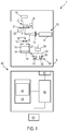
- Figure 1 is a schematic representation of a device 1 according to an embodiment.
- the device 1 is set up to examine biological objects 3, 4 of a sample 2 using Raman spectroscopy.
- the biological objects 3, 4 are at least temporarily locked by a locking device 5 during a measurement.
- a “locking” is generally understood here to mean that the biological object is localized locally.
- the biological object 3, 4 can, but does not have to be, immobilized.
- the localization takes place in a recess of a microslide or a microwell plate that is slightly larger than the biological object 3, 4.
- the device 1 can be set up to detect and automatically evaluate the reaction of one or more biological objects 3, 4, which are locked by the locking device 5, to one substance or several different substances.
- the device 1 can comprise a supply device 30 which is set up to supply one or more substances to one or more of the biological objects 3, 4.
- the device 1 comprises a Raman spectroscopy system 10 and a computing device 40.
- the Raman spectroscopy system 10 is set up to detect a Raman spectrum of a biological object or a plurality of biological objects 3, 4 that are locked by the locking device 5.
- the biological objects 3, 4 can each be selected from a cell, a cell clone, a bacterium and other biological objects.
- the device 1 can optionally comprise a microscopy system for locating and / or observing microscopic objects.
- the device 1 comprise a fluorescence unit, for example to stimulate intrinsic fluorescence of biological objects.
- the Raman spectroscopy system 10 comprises a light source 11.
- the light source 11 can be a laser.
- the laser can have a cell-friendly laser wavelength.
- the laser wavelength can be 785 nm.
- the light source 11 is set up to output an excitation beam 17.
- a Raman spectrometer 14 receives light 18 scattered by Stokes processes and / or anti-Stokes processes on one or more of the biological objects 3, 4.
- the Raman spectrometer 14 can comprise a diffractive element 15 and an image sensor 16 in order to measure the Raman spectrum biological object 3, 4 to be recorded.
- the Raman spectroscopy system 10 can comprise further elements in a manner known per se, for example focusing optical elements 12, 13, which can be designed as lenses, and / or diaphragms.
- the light source 11 can output the excitation beam with a wavelength in the near infrared range.
- the light source 11 can output the excitation beam with a wavelength that allows the examination of native cells with the aid of Raman spectroscopy.
- the excitation beam 17 can be focused by an objective in such a way that an electromagnetic gradient is created by means of which biological objects can be drawn into the laser focus and held there. This can be done simultaneously with the spectrum acquisition, i.e. the objects are locked in the laser focus during Raman scattering.
- the optical holding forces can also be used independently of the acquisition of Raman spectra, for example to transport the biological objects from one place to another.
- the device 1 comprises a computing device 40.
- the computing device 40 can be a computer or can comprise a computer.
- the computing device 40 is coupled to the Raman spectroscopy system 10.
- the computing device 40 can control the acquisition of the Raman spectrum by the Raman spectroscopy system 10.
- the computing device 40 can control the light source 11 so that it can be used once for capturing Raman spectra and that the biological objects are simultaneously kept in the laser focus.
- the light source 11 can, however, also be controlled in such a way that it can hold and / or transport biological objects independently of the detection of a Raman spectrum.
- the computing device 40 can control the Raman spectroscopy system 10 in such a way that Raman spectra take place in a spatially resolved manner on the biological objects 3, 4 locked by the locking device 5.
- Different biological objects 3, 4 can be subjected to a Raman spectroscopy sequentially in order to record their reaction to a substance, for example.
- the control with which the different objects are subjected to a Raman spectroscopy sequentially can be automated.
- the computing device 40 has an interface 41 in order to receive data from the image sensor 16 of the Raman spectroscopy system 10.
- the computing device 40 has an integrated semiconductor circuit 42 which can include a processor or controller and which is set up to evaluate the detected Raman spectrum.
- the integrated semiconductor circuit 42 is set up to evaluate the at least one Raman spectrum.
- the integrated semiconductor circuit 42 can, for example, subject a plurality of recorded Raman spectra to a statistical analysis each during or after the biological objects are exposed to a substance.
- the statistical analyzes can include a principal component analysis, a cluster analysis and / or a linear discriminant analysis (LDA analysis).
- LDA analysis linear discriminant analysis
- the semiconductor integrated circuit 42 may be configured to detect the presence or absence of certain Raman peaks or to determine the spectral weight of Raman peaks which are associated with certain cellular reactions.
- the integrated semiconductor circuit 42 can be set up, for example, to quantitatively determine by evaluating the at least one Raman spectrum Whether cells, cell clones, bacteria, germs or other biological objects show functional changes in response to a substance, for example in apoptosis, necrosis or another functional state.
- the integrated semiconductor circuit 42 can be set up to evaluate the reaction to the substance supplied to this biological object in each case as a function of time for one or more biological objects. In this way, the reaction of several biological objects can be monitored partially or fully automatically and time-dependently in parallel.
- the integrated semiconductor circuit 42 can recognize different cell types, for example different blood cells, on the basis of the position of Raman peaks, the peak height, the steepness of the flanks and the characteristic distribution of the peaks (peak pattern) for the corresponding cell type.
- Information about the position and / or the spectral weight of different Raman peaks for the different cell types can be stored in a non-volatile memory in the device 1.
- the information about the position and / or the spectral weight of different Raman peaks for the different cell types, different bacteria, different germs or other biological objects can be obtained from the device 1 by methods of supervised learning or others Machine learning techniques are identified.
- the semiconductor integrated circuit 42 can process acquired Raman spectra in different ways. For example statistical methods, e.g. principal component analysis, cluster analysis techniques, or LDA techniques can be used. Additionally or alternatively, Raman spectra can be compared with reference data in order to determine which cell types are present and to determine the reactions of the cell types to different substances.
- statistical methods e.g. principal component analysis, cluster analysis techniques, or LDA techniques can be used.
- Raman spectra can be compared with reference data in order to determine which cell types are present and to determine the reactions of the cell types to different substances.
- the computing device 40 can comprise a memory 43 in which the reference data 44 are stored, which the integrated semiconductor circuit 42 can also use when evaluating the Raman spectrum.
- the computing device 40 can comprise an optical and / or acoustic output unit 45, via which information is output depending on the analysis of the at least one Raman spectrum.
- the device 1 can be set up to output information via the optical and / or acoustic output unit 45, which indicates drug resistance to one or more active ingredients, compatibility of one or more chemicals and / or the effect of one or more toxic substances.
- the device 1 can have an image acquisition device 19.
- the image acquisition device 19 can be set up to acquire an image of the biological objects 3, 4 which are locked by the locking device 5.
- the image capture device 19 can be coupled to the integrated semiconductor circuit 42.
- the integrated semiconductor circuit 42 can recognize the biological objects 3, 4 in the captured image by automatic object recognition.
- the image acquisition device 19 can be configured such that its imaging optics are configured separately from an objective of the Raman spectroscopy system 10.
- the image capturing device 19 can be designed such that the optical beam path from the locking device 5 to an image sensor of the image capturing device 19 does not pass through any optical components of the objective of the Raman spectroscopy system 10.
- the image capturing device 19 can be designed such that the optical beam path from the locking device 5 to the image sensor of the image capturing device 19 passes through at least one lens of the objective of the Raman spectroscopy system 10.
- the integrated semiconductor circuit 42 can control an actuator 22 as a function of the image captured by the image capturing device 19 in order to sequentially position different biological objects 3, 4 held by the locking device 5 for measurement by the Raman spectroscopy system.
- the integrated semiconductor circuit 42 can control the actuator 22 as a function of the relative position between two biological objects in order to sequentially position different biological objects for Raman scattering.
- the actuator 22 can be set up to bring about a relative movement between the locking device 5 and the Raman spectroscopy system 10.
- the actuator 22 can comprise a motor or another drive, for example a piezoelectric drive, in order to bring about the relative movement.
- the actuator 22 can be set up to bring about the relative movement in two and preferably in three spatial directions orthogonal to one another.
- the actuator 22 can be set up to move a carrier 21 on which the locking device 5 is attached relative to the Raman spectroscopy system 10.
- the actuator 22 can alternatively or additionally be designed to move at least one optical component of the Raman spectroscopy system 10 relative to the carrier 21.
- the carrier 21 can be a microscope stage.
- the device 1 comprises a supply device 30 for supplying at least one substance.
- the feed device 30 can be set up to feed several different substances to different biological objects 3, 4.
- the feed device 30 can comprise a reservoir 34 for a substance 31.
- the substance 31 can comprise an active substance, a toxin, a chemical or another substance:
- the substance 31 can be in solution.
- a conveying device 36 can be set up to convey the substance 31 from the reservoir 34 to the locking device 5.
- the delivery device 36 can comprise a pump or a plurality of pumps in order to deliver different substances independently of one another.
- the conveying device 30 can convey the substance 31 via a line 37 to a supply element which supplies the substance 31 to a biological object 3.
- the conveying device 30 can be set up to selectively feed the substance 31 only to exactly one biological object or only to a group of biological objects, so that the other biological objects are not exposed to the substance 31.
- the feed device 30 can comprise a further reservoir 35 for a further substance 32.
- the further substance 32 can be different from the substance 31 or identical to the substance 31.
- the further substance 32 can comprise an active substance, a toxin, a chemical or another substance: the further substance 32 1 can be in solution.
- the delivery device 36 can be set up to deliver the further substance 32 from the further reservoir 35 to the locking device 5.
- the conveying device 36 can be set up to set a volume flow of the further substance 32 independently of a volume flow of the substance 31 to the locking device 5.
- the conveying device 30 can convey the further substance 32 via the line 37 or a line different therefrom to a feed member which feeds the further substance 32 1 to a biological object 4.
- the conveying device 30 can be set up to selectively feed the further substance 32 only to exactly one biological object or only to a group of biological objects, so that the other biological objects are not exposed to the further substance 32.
- the line 37 can comprise several different lumens.
- the line 37 can be a multi-lumen line in which different lumens are integrated in a tube in order to convey different substances 31, 34 via the same tube to the same or different biological objects 3, 4.
- a channel can be used in which the substances are transported.
- a laminar flow in the channel can transport the substances.
- the Raman spectroscopy system 10 and the feed device 30 are shown schematically as a structurally integral unit in FIG. 1, at least part of the feed device 30 can also be provided separately from a housing of the Raman spectroscopy system 10.
- the reservoir 34 and / or the further reservoir 35 which are formed in a storage container 33, can be provided separately from the housing of the Raman spectroscopy system 10.
- the device 1 can comprise a collecting area 6 in which the objects transported out of microwells of a microfluidic chip with the aid of optical tweezers or by other devices and, for example, brought into a fluid channel or fluid flow can be collected.
- the reservoir 34 and / or the further reservoir 35 can be reversibly and non-destructively releasably inserted into the storage container 33 and removed from the storage container 33.
- the functions of the computing device 40 can also be integrated in a housing of the Raman spectroscopy system 10.
- the Raman spectroscopy system 10 and the computing device 40 can be designed as mobile, in particular as portable, units.
- the device 1 can be used in a multitude of different ways and in particular with a multitude of different samples 2.
- the locking device 5 can be a microstructure for the arrangement of biological objects, for example cells and / or bacteria.
- the image recording device 19 can capture a large-area overview image, which is automatically evaluated in order to recognize whether biological objects, for example cells and / or bacteria, are locked on the locking device 5.
- the computing device 40 can, for example, evaluate contrast information, dark field information, fluorescence and / or autofluorescence in order to determine the positions of biological objects.
- microwells ie wells with cells or other biological objects, are saved. Raman spectra are recorded. Since the biological objects are held in the microwells, for example by gravity, adhesion or a meshwork, they can after the administration of the Active ingredient and automatically approached and measured at certain times.
- the device 1 can have a spectrum database.
- the computing device 40 can automatically sort the recorded spectra according to the locations, for example according to the microwells, in which biological objects are contained.
- a kinetic course of the reaction of biological objects to one or more different substances can be recorded.
- a statistical evaluation of the Raman spectra can be carried out to record the kinetic course of the reaction, for example by means of a principal component analysis, a cluster analysis and / or an LDA.
- the computing device 40 can be set up to determine a species of the biological object, for example a cell type. For this purpose, the computing device 40 can carry out a comparison with previously stored characteristic spectra. The comparison can also take place through a statistical evaluation of the Raman spectra, for example through a main component analysis, a cluster analysis and / or an LDA.
- the device 1 can be set up for parallel analysis of biological objects and / or their reaction to active substances, toxins, chemicals or other substances.
- the device 1 can, for example, use times at which an active ingredient is currently being supplied to a biological object in order to record and optionally also evaluate a Raman spectrum of a further biological object that is not covered by a supply element.
- a locking device 5 which is designed as a micromatrix, can be used for multiplexed analysis of cells, cell clusters or cell clones by means of Raman spectroscopy.
- the size of microwells determines whether only a cell or a cell clone or a cluster of cells that grows through the multiplication of a single cell is examined with Raman spectroscopy.
- the device 1 can be set up to automatically compensate for background signals from the locking device 5.
- the actuator 22 in addition to detecting a Raman spectrum that is assigned to a biological object, the actuator 22 can be actuated such that the Raman spectrum of the locking device 5 is detected at a position where no biological object is present.
- difference spectra formation in which, for example, a weighted difference between a Raman spectrum of a biological object and the Raman spectrum of the locking device 5 is determined, background-corrected Raman spectra can first be obtained, which are then used with statistical analysis techniques such as cluster analysis, principal component analysis and / or an LDA can be further analyzed in order to determine a kinetics of a reaction to a substance.
- the device 1 can optionally be set up to sort biological objects.
- a microfluidic system can be used for this purpose.
- the biological objects can be sorted depending on their reaction to one or more substances 31, 32.
- the device 1 can be used both to identify bacterial pathogens in the bloodstream (bacteremia) and to evaluate the effectiveness of antibiotics or other active substances. While the detection of pathogenic germs and the determination of the reaction to active substances is described by way of example, other types of cells can also be examined in order to determine the reaction of cells to active substances.
- the computing device 40 can compare the recorded Raman spectra with data from Raman spectra which were recorded for the following genera: Gram-positive staphylococci, streptococci and Enterococci and Gram-negative Escherichia, Klebsiella, Serratia and Pseudomonas.
- the device 1 enables the combination of rapid germ detection and resistance determination.
- the device 1 enables an optimally effective antibiotic to be found quickly on a patient-specific basis in an automatic or computer-aided procedure.
- the stay during treatment in the hospital could be significantly shortened and thus costs could be reduced / saved accordingly.
- the likelihood of developing resistance would decrease in the long term.
- Raman spectra of living pure cultures of relevant pathogens of bacterial sepsis can be measured, which are stored as Raman databases in the computing device 40 or in a separate memory. Both the bacteria themselves and their supernatants can be examined with Raman spectroscopy.
- blood samples from healthy people can be measured and compared with those from infected patients.
- Samples of the blood plasma and the colonies from the blood cultures can be measured with the Raman spectroscopy system 10 for the subsequent identification of bacterial pathogens.
- the data obtained can be compared with the spectra of the databases in order to find typical detection patterns for the individual pathogens.
- the locking device can be designed in such a way that it eliminates the amount of blood cells and concentrates the germs at a predefined location for the detection of the Raman spectra.
- the locking device can comprise a curved fluid channel and / or a membrane.
- the device 1 can also allow resistance testing. For the determination of resistance and for finding suitable active substances, the pathogens are examined alive by the device 1. It can be different Active ingredients 31, 32 are supplied, with Raman spectra of the biological objects being recorded during or after the supply of the active ingredients in order to determine to which active ingredient or which active ingredient combination they react and / or for which active ingredient or for which active ingredients 31, 32 active ingredient resistances exist.
- the samples 2 and the locking devices 5 used can have different configurations.
- the plasma can be separated from the serum, the cellular components, by lysing the cells and / or by centrifugation or by means of a membrane.
- a pellet with the bacteria which remains, for example, as sediment after centrifugation, or the corresponding layer after density gradient centrifugation, can be spread, for example pipetted, onto a slide.
- the locking device can also concentrate the bacteria via osmotic processes.
- the slide can be coated with a layer of a fine-meshed matrix, a so-called "scaffold".
- the matrix can comprise hydrogel, collagen or agar.
- the entire slide can be centrifuged so that the bacteria migrate into the layer.
- the bacteria can be mixed with the hydrogel, collagen or agar and plated out in the mixture so that the bacteria are locked in the meshwork during the crosslinking process.
- the mobile germs can be arrested in the pores of the matrix or the scaffold so that they cannot swim away.
- the matrix as a locking device can store liquid so that the bacteria can live and multiply in it.
- the device 1 can be set up to transport nutrients or active substances to the bacteria in a microincubator space.
- the locking device can have an engraving in order to be able to find the germs better microscopically or to be able to find them again after transfer to / from the incubator.
- the germs can optionally be further concentrated.
- the bacteria can be pressed through a fine-meshed matrix, for example hydrogel or collagen which the liquid lets through, but the germs do not.
- the matrix can be applied to a grid, for example an open-pored carrier with a grid structure.
- the grid also serves as a pattern for easier finding of the germs under a microscope or in an image captured with the image recording device 19.
- the carrier can be designed so that it can be transferred into a culture dish with a glass bottom and measured by the Raman spectroscopy system 10.
- a double-deck sterile filter unit can be used for concentration.
- Such a unit can have several sections in which filters with different pore sizes are used. Osmosis can be used to concentrate.
- the pellet or the relevant band of a density gradient centrifugation with the bacteria can be mixed with a hydrogel, agar or a similar matrix and injected into microchannels or microwells for a cell culture.
- the individual microstructures can have a height of 100 ⁇ m to 3 mm.
- the individual microstructures can have a height of 50 ⁇ m to 3 mm.
- the microchannel slide can be centrifuged so that the bacteria with the still liquid hydrogel or agar can settle on the bottom or in the microwells.
- the hydrogel or agar allows the germs to grow in the microwells. On the one hand, the germs can be measured and determined. At the same time, growth can be observed. Active substances such as antibiotics can then be injected into the various channels and the reaction of the germs to them can be measured using Raman spectroscopy.
- the germs can lie on or at least directly below the surface of the locking device 5.
- the structures of the locking device 5 restrict the motility of the germs.
- the germs can via self-fluorescence, for example under ultraviolet (UV) light, can be found automatically by evaluating the image captured by the image recording device 19.
- the germs can also be identified by a user and their positions drawn in via a user interface.
- the germs can be automatically recognized and marked using image analysis software.
- the meshwork of the matrix can be designed in such a way that the bacteria cannot simply escape from the interstices and they can thus be more easily held and measured with a laser, for example with an optical trap.
- the matrix can be designed such that nutrients can diffuse in the matrix in order to be able to follow the growth of the bacteria and to be able to test the effect of antibiotics or other active substances 31, 32.
- the microwells of the locking device can automatically be optically scanned and searched for biological objects.
- Raman spectra can be measured with the help of an optical trap effect, since even in close-meshed matrices there is still a certain residual freedom of movement of the germs, so that they are held by an optical trap during Raman spectroscopy.
- the Raman excitation during Raman spectroscopy can thus, in specific embodiments, generate an optical trap at the same time.
- coupling technique e.g. Free beam guidance and waiver of fiber guidance
- both a Raman excitation and an electromagnetic gradient field can be generated by a lens. This leads to a trapping effect, i. an optical trap is created.
- the present invention makes use of these possibilities to analyze and arrest biological objects.
- the device according to the invention can be designed in such a way that it comprises more than one laser, for example two lasers.
- the device then comprises at least one laser for Raman excitation and at least one second laser which generates an optical trap for the biological object.
- Raman spectra can be measured before the administration of active substances and after or during the administration of active substances. It is possible, but not absolutely necessary, to repeat the measurements on the identical biological objects 3, 4. The measurements can be repeated in a time series in order to determine the kinetics of the reaction to one or more active substances 31, 32 as a function of time. The acquired Raman spectra can be further analyzed in various ways to determine the kinetics of the reaction, such as with reference to FIG Figure 1 to Figure 23 will be further described. In particular, a fully automated and partially automated data evaluation can be carried out with which the computing device 40 determines which active substances 31, 32 are resistant to active substances and / or which active substances 31, 32 enable a promising therapy for the respective patient.
- the reaction of biological objects 3, 4 to the active substances 31, 32 can be determined immediately. Suitable antibiotics or other active substances can be determined automatically by the device 1. If there is a mixture of germs, the same germs or colonies can be measured after a certain time.
- the devices and methods according to exemplary embodiments allow, for example, the automatic determination of personalized therapies for pathological conditions such as sepsis, without being restricted to this.
- Starting from a living blood smear or directly from a blood drop it can be determined which germs are present and / or which active substances enable successful therapy.
- the blood drop can, for example, be introduced into a special fluidic chip that is set up to eliminate the blood cells and concentrate the germs, which can then be examined by Raman scattering.
- biological objects such as cells, cell clusters, cell clones, germs, for example bacteria, or other biological objects can be examined marker-free.
- the cells can be alive or be examined non-destructively.
- Devices and methods can be implemented in such a way that no pretreatment with marker molecules is required.
- the reaction to substances such as active substances, toxins, chemicals or other substances can be determined marker-free, without having to establish physical contact between a measuring device and the biological objects.
- the measurement throughput can be increased compared to other contact measurement techniques.
- FIG. 2 shows schematically a sample 50 which has a locking device 51.
- the locking device 51 is not within the scope of the claims.
- the locking device 51 can comprise a hydrogel, a collagen, or another material.
- the locking device 51 can have cavities for receiving biological objects 52.
- the cavities can be designed in such a way that they are permeable to nutrients for the biological objects 52.
- the device 1 can automatically detect the positions of the biological objects 52 in the locking device 51.
- the computing device 40 can automatically evaluate the image captured by the image capturing device 19.
- self-fluorescence of the biological objects 52 can be used for position detection.
- the device 1 can have a light source for stimulating its own fluorescence.
- the device 1 can control the excitation laser and the image sensor of the Raman spectroscopy system 10 as well as the actuator 22 depending on the detected positions of the biological objects 52 in order to selectively detect Raman spectra on different biological objects 52.
- Substances such as active ingredients, toxins, chemicals or other substances can be conveyed from the feed device 30 to the locking device 51 in order to observe the reaction of the biological objects 52 to the substance (s).
- hydrogel, collagen or another matrix, in the interstices of which biological objects 52 are held can additionally be introduced into a microwell plate or another microslide, as described with reference to FIG Figure 3 to Figure 10 is described in more detail.
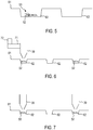
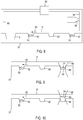
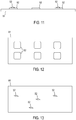
- FIG 3 shows schematically a sample which has a locking device 61.
- the locking device 61 can be used in the device 1.
- the locking device 61 can be designed as a microwell plate or some other device which has a plurality of receptacles 62 for receiving biological objects.
- the receptacles 62 are each designed as depressions, for example as microwells.
- the receptacles 62 can, however, also be areas with a coating of increased cell adhesion to which the cells can adhere.
- the coating can for example be a hydrophilic coating.
- the receptacles 62 can have a depth and / or lateral dimensions which are adapted to the dimensions of the biological objects to be measured.
- the receptacles 62 can be dimensioned such that only one cell of the desired cell type can be received in the receptacle 62.
- the receptacles 62 can also be dimensioned to receive cell clones or cell clusters which comprise a plurality of cells.
- the receptacles 62 are designed as microwells and adapted in such a way that when active ingredients, e.g. Toxins, biological objects such as cells or cell clones that are located inside the microwells cannot be flushed out of them.
- active ingredients e.g. Toxins
- biological objects such as cells or cell clones that are located inside the microwells cannot be flushed out of them.
- a preferred embodiment of the microwells provides that they have a depth that at least corresponds to their diameter.
- the device 1 can automatically detect the positions of the receptacles 62 when the locking device 61 is used.
- the computing device 40 can automatically evaluate the image captured by the image capturing device 19 in order to identify a position and type of the receptacles 62 of the locking device 61.
- the device 1 can furthermore be set up to automatically recognize in which of the receptacles 62 biological objects 52 are positioned. Transmitted light or bright field illumination can be used for this. However, it is also possible, for example, to use the inherent fluorescence of the biological objects 52. The objects can also be specifically loaded with fluorescent molecules so that cells marked with fluorescence can be identified in a targeted manner. For this purpose, the device 1 can have a light source for exciting its own fluorescence or fluorescence. The positions of the receptacles 62, in each of which a biological object is positioned, can be stored in a memory of the computing device 40. For optimal use of the measurement time, the Raman spectroscopy system 10 and the actuator 22 can be controlled in such a way that targeted measurements are made on those recordings 62 in which biological objects are contained.
- At least one Raman spectrum can be recorded on a recording 62 which does not contain a biological object 52 in order to at least partially compensate for the influence of the locking device 51, for example by forming difference spectra.
- the Raman spectrum recorded at the empty receptacle 62 can be subtracted from a Raman spectrum assigned to a biological object 52.
- a weighting can be undertaken when forming the difference in order to largely suppress the background signal of the locking device 62.
- the device 1 can control the excitation laser and the image sensor of the Raman spectroscopy system 10 as well as the actuator 22 depending on the detected positions of the biological objects 52 in order to selectively detect Raman spectra on different biological objects 52, which are held in recordings 62.
- Substances such as active ingredients, toxins, chemicals or other substances can be conveyed from the feed device 30 to the locking device 51 in order to observe the reaction of the biological objects 52 to the substance (s).
- the biological objects locked by the locking device can retain a residual mobility in the corresponding receptacles.
- the biological objects can be held in one position by the interaction of the locking device with an optical trap potential, which can be provided, for example, by the excitation beam of the Raman spectroscopy system 10 itself, in order to enable the Raman spectra to be recorded or / and improve the quality of the Raman data.
- Figure 4 shows a plan view of an embodiment of the locking device 62.
- the receptacles 62 which can be designed as depressions, can be provided in a regular arrangement. Channels can connect multiple recordings to facilitate the delivery of substances to multiple biological objects in order to record the reaction to these substances with Raman spectroscopy.
- Each receptacle 62 of the locking device 61 can be designed in such a way that it can only accommodate exactly one biological object of a certain type, for example only one cell of one cell type.
- the recordings can also be configured such that they can record several biological objects of a certain type, as in FIG Figure 5 is shown.
- FIG. 6 is a sectional view of a locking device 61 according to a further embodiment.
- the locking device 61 can be designed as a microwell plate or some other device which has a plurality of receptacles 63 for receiving biological objects.
- the receptacles 63 can each be designed as depressions, for example as microwells.
- the receptacles 63 can have a depth and / or lateral dimensions which are adapted to the dimensions of the biological objects to be measured.
- the receptacles 63 can be dimensioned such that only one cell of the desired cell type can be received in the receptacle 63.
- the receptacles 63 can be dimensioned to receive cell clusters or cell clones 53 which comprise a plurality of cells 52.
- the receptacles 62, 63 of the locking device 61 serve as holding areas which are set up to lock biological objects at least temporarily.
- Figure 6 shows a partial view of the device 1 which can be used in combination with any of the various locking devices.
- a feed member 38 of the feed device 30 is set up to feed one substance or a plurality of substances to a biological object or a plurality of biological objects that are locked by the locking device.
- the delivery member 38 may comprise a nozzle through which an active ingredient, toxin, chemical, or other substance is delivered.
- the feed member 38 can be connected to at least one reservoir 34, 35 via the delivery device 36.
- the feed device can comprise one or more microfluidic channels through which or through which a substance is fed to a multiplicity of cells or cell clusters.
- Several channels can exist next to one another, wherein the feed device can be set up to apply substances of the same or different types in the several channels.
- the device 1 can have a further actuator 72 for producing a relative movement between the locking device 61 and the feed member 38.
- the further actuator 72 can be actuated independently of the actuator 22.
- the further actuator 72 can be designed to move the feed element 38 relative to the locking device 61 and / or to move the locking device 61 relative to the feed element 38.
- the further actuator 72 can, for example, adjust a holder 71 for the feed member linearly in two or three orthogonal spatial directions.
- Channels can be present in the locking device 61 in order to connect some of the receptacles 62 with one another, so that the substance supplied via the feed member 38 is passed on to biological objects in a plurality of receptacles 62.
- the statistics of the measurement can thus be improved.
- FIG. 7 shows a partial view of the device 1 which can be used in combination with any of the various locking devices.
- a feed member 38 of the Feed device 30 is set up to feed one substance or a plurality of substances to a biological object or a plurality of biological objects that are locked by the locking device.
- Another supply member 39 is set up to supply a further substance.
- the supply members 38, 39 can supply different substances.
- the feed element 38 and the further feed element 39 can each comprise a nozzle through which an active substance, a toxin, a chemical or another substance is released.
- the feed member 38 can be connected to at least one reservoir 34 via the conveying device 36.
- the further supply element 39 can be connected to at least one further reservoir 35 via the conveying device 36.
- the supply device 30 can be set up to supply the same or different substances to several different biological objects in parallel via the supply organs 38, 39.
- the biological objects can be subdivided into a plurality of groups by the computing device 40 or in a user-defined manner, which include a first group and a second group, each with a plurality of biological objects.
- a first substance can be supplied to biological objects of the first group via the supply element 38.
- a second substance can be supplied to biological objects of the second group via the further supply element 39.
- the reaction of the biological objects of both groups to the different substances can be examined by Raman spectroscopy.
- the locking device 61 can have channels which connect some of the receptacles 62 to one another, so that the substance supplied via the feed member 38 is passed on to biological objects in a plurality of receptacles 62.
- the channels can define several groups of recordings 62 that are disjoint from one another, for example a first group of recordings connected to one another and a second group of recordings connected to one another, disjoint therefrom.
- the Raman spectra that are assigned to biological objects can be recorded by Raman spectroscopy on the biological objects themselves.
- Raman spectra assigned to biological objects can be can also be detected on a fluid, for example a liquid, which at least partially covers the biological objects. In this way, metabolites or other substances discharged from the biological objects can be detected by Raman spectroscopy in order to determine the reaction to a substance.
- Figure 8 shows a partial view of the device 1 which can be used in combination with any of the various locking devices.
- the receptacles 62 of the locking device 61 are at least partially covered by a fluid 81.
- the locking device 61 can comprise a collective receptacle 6 or a plurality of collective receptacles.
- the collecting receptacle (s) 6 can be formed in the microfluidic chip. Cells from the receptacles 62 can be brought into the collecting receptacle (s) 6 via the fluid flow.
- a transfer from a receptacle 62 into the collecting receptacle 6 can move the cell from the receptacle 62 into the flow of the fluid 81, transporting the cell in the flow of the fluid 81 and moving the cell from the flow of the fluid 81 into the collecting receptacle 6 include.
- Moving out of the receptacle 62 into the flow of fluid 81 and / or moving out of the flow of fluid 81 into the collecting receptacle 6 can each be implemented using optical means, in particular a movable optical trap.
- a decision as to which of several collective recordings is to be used to collect a cell can be made as a function of the Raman spectra previously recorded in the record 62.
- a decision as to whether a cell should be collected in a collective receptacle 6 at all can be made as a function of Raman spectra previously recorded in receptacle 62. The corresponding decision can be made automatically by the device 1 depending on the previously acquired Raman spectra.
- the collection receptacles 6 allow cells to be collected separately depending on their properties.
- the device 1 can be configured to move the fluid 81 in a fluid flow.
- the fluid 81 can be a liquid.
- the device 1 can, for example, have a pump 83 or some other device for generating a flow rate of the fluid 81.
- At least one channel 84, 85 can be provided for supplying the fluid from the locking device 61 and / or for discharging the fluid from the locking device 61.
- the device 1 can have a device for selectively moving biological objects between a fluid flow 82, which flows over at least some of the receptacles 62, and the receptacles 62.
- the device can comprise optical tweezers or other electrical and / or magnetic fields or waves with which biological objects 52 are moved between the fluid flow 82 and the receptacles 62.
- the fluid flow 82 does not necessarily have to be implemented as a closed fluid circuit.
- the fluid stream 82 can be used to sort biological objects 52 depending on the detected Raman spectra.
- Biological objects 52 can be transported into a plurality of different containers by a controllable device for controlling the fluid flow 82, depending on which reaction to a substance the biological objects show on the basis of the Raman spectra and / or depending on the reaction determined by means of Raman spectroscopy Type of biological object.
- the supply of one or more substances can be integrated into the fluid flow 82.
- a supply member 38 for supplying one or more substances can have an outlet opening which is in fluid connection with a supply channel 84 for the fluid 81.
- the concentration of the substance (s) 31, 32 in the fluid 81 can be controlled or regulated.
- Figure 9 and Figure 10 illustrate the mode of operation of a device for selectively moving biological objects between the fluid flow 82 and the receptacles 62.
- the device for selectively moving biological objects can comprise optical tweezers.
- a radiation field 88 can have a focal region 89 which can be moved perpendicular to a surface of the locking device 61.
- the radiation field 88 can be generated with the excitation beam of the Raman spectroscopy system 10 or with a different laser beam.
- a biological object 54 is moved between the fluid flow 82 and a receptacle 65, as in FIG Figure 10 is shown.
- the biological object 54 may have previously separated from the fluid flow 82 due to the force of gravity acting on it.
- the biological object 54 can be held in the receptacle 54 by the radiation field 88 and / or by the edges of the receptacle 65.
- the radiation field 88 does not have to remain activated in order to keep the biological object 54 in the receptacle 65.
- the biological object can, for example, also settle in the receptacle 65 under the action of gravity after it has been flushed in by means of fluid flow 82.
- the biological object 54 can be moved from the fluid stream 82 into the receptacle 65 using an optical or other radiation field.
- cells can be received in the receptacles 62, 65 in that the cells are flushed in through the fluidic channel and settle in the receptacles 62, 65 due to the force of gravity.
- a transfer from the receptacles 62, 65 into the fluid flow can take place with an optical trap, by other electromagnetic fields or waves, by selective application of fluid pressure, or in another way.
- the cells can then be transferred from the fluid flow into collecting receptacles of the microfluidic chip.
- the device 1 can be designed such that the biological objects can be reversibly transferred from the fluid flow 82 into a receptacle 65 and from the receptacle 65 back into the fluid flow 82 in a non-destructive manner.
- Figure 11 shows a sectional view of a locking device 91 not falling under the claims and Figure 12 shows a plan view of the locking device 91.
- the locking device 91 has areas 92 which are arranged on a surface of the locking device 91 in a structured manner.
- the areas 92 can be coatings or have another configuration.
- the areas 92 are designed to lock biological objects 52 at least temporarily thereon.
- the areas 92 may be provided in a regular or irregular arrangement.
- the device 1 can automatically detect the positions of the areas 92 when the locking device 91 is used.
- the computing device 40 can automatically evaluate the image captured by the image capturing device 19 in order to identify a position and type of the areas 92 of the locking device 91.
- the device 1 can furthermore be set up to automatically recognize in which of the areas 92 biological objects 52 are positioned.
- a contrast, autofluorescence or fluorescence marking of the biological objects 52 can be used.
- the device 1 can have a light source for exciting the self-fluorescence or the fluorescence.
- the positions of the areas 92, in which a biological object is respectively positioned, can be stored in a memory of the computing device 40.
- the Raman spectroscopy system 10 and the actuator 22 can thus be controlled so that targeted measurements are made in those areas 92 where biological objects are locked.
- At least one Raman spectrum can be recorded in a region of the locking device 92 which does not contain a biological object 52 in order to at least partially compensate for the influence of the locking device 91, for example by forming difference spectra.
- the device 1 can control the excitation laser and the image sensor of the Raman spectroscopy system 10 as well as the actuator 22 depending on the detected positions of the biological objects 52 in order to selectively detect Raman spectra on different biological objects 52 that are arrested at the areas 92.
- Substances such as active ingredients, toxins, chemicals or other substances can be conveyed from the feed device 30 to the locking device 91 in order to observe the reaction of the biological objects 52 to the substance (s).
- Figure 13 shows a locking device 95 which does not fall under the claims and which has a surface on which biological objects 52 can adhere to it.
- the locking device 95 can have a homogeneous or structured coating that can facilitate the growth of the biological objects.
- the locking device 95 can be a matrix mixed with cells, for example incubated, in which the cells are randomly distributed.
- the device 1 can automatically find the position of the cells via image recognition. For this purpose, either a contrast, an autofluorescence or a fluorescence of the cells can be evaluated.
- Figure 14 shows Raman spectra 101, 102 for a biological object.
- a first Raman spectrum 101 can be recorded before a substance is administered.
- At least one second Raman spectrum 102 can be recorded during or after administration of the substance.
- On the basis of the shift in wave numbers at which Raman peaks are present and / or on the basis of the spectral weight of different Raman peaks 104, 105 it can be determined whether the biological object shows a reaction to the substance or not. These differences can be used by the device 1 to automatically determine the reaction of the biological object to the substance, for example to detect drug resistances.
- Different wave numbers or wave number intervals 106, 107, 108 can be evaluated in order to determine the reaction of the biological object.
- the Raman spectra can be in one or more of the wavenumber intervals 813-832 cm -1 , 864-888 cm -1 , 911-920 cm -1 , 984-1070 cm -1 , 1038-1051 cm -1 , 1078-1091 cm -1 , 1100-1131 cm -1 and / or 1430-1443 cm -1 can be evaluated in order to detect a transition from living to apoptotic states of biological objects. This can be relevant both for determining the compatibility of chemical substances and for determining drug resistance.
- Patterns of the spectra can be detected by the device 1 and differences in the patterns can be used as discrimination variables and optionally determined. Examples of such patterns include one or more peak positions, peak heights, steepness of the flanks, shape and position of the valleys between the peaks and / or other variables that can be derived from the spectrum.
- the Raman spectrum or the Raman spectra can be processed further by the computing device 40.
- the computing device 20 can, for example, be a Perform cluster analysis, principal component analysis, or LDA of the acquired Raman spectra. Before such an analysis, signal components of the locking device can be at least partially suppressed by forming the difference spectrum.
- the result of the cluster analysis can be used to quantitatively analyze reactions and a speed of reactions of biological objects to one or more substances.
- FIG. 10 illustrates exemplary results 100 of a principal component analysis performed by computing device 40 to determine whether a biological object is responding to administration of a substance.
- the main component analysis is carried out for a Raman spectrum or several Raman spectra that were recorded on the same biological object 3, 4.
- the data points are represented according to a pair of the different major components PC-1 and PC-2.
- Figure 15 Figure 10 shows data points 101 associated with living cells and data points 102 associated with apoptotic cells. Comparable data points can also result from a changed functional state of the cells after the administration of the active substance. Similar structures result from a main component analysis of the Raman spectra of other biological objects such as germs, eg bacteria.
- the result of the main component analysis of the Raman spectra recorded on the biological objects can be evaluated to determine whether and how many data points lie in different regions 103, 104 of the coordinate system spanned by several main components. For example, it can be determined how many data points lie in a region 103 which is assigned to living cells of a specific cell type. It can be determined how many data points lie in a region 104 which is assigned to apoptotic cells of the same cell type. It can be determined how many data points are in further regions of the coordinate system spanned by several main components, which are assigned to other biological objects and / or other functional states of the biological objects.
- the data points obtained by the principal component analysis shift depending on whether and in what way a biological object reacts to a substance.
- the computing device 40 can automatically determine which cell types are present and / or whether the cells transition into an apoptotic state in response to different substances.
- Figure 16 illustrates the evaluation of the kinetics of a reaction of a biological object to a substance. The result of a principal component analysis is shown in each case.
- the data points 111 of a main component analysis of the Raman spectrum of a biological object lie in a region 114 of the space spanned by the main components.
- the area 114 corresponds to functionally intact biological objects, for example functionally intact living cells or bacteria.
- the data points are shifted.
- the data points 112 which are determined by principal component analysis of the Raman spectrum of a biological object, may have left the region 114. This indicates that a functional change, for example through transition to an apoptotic state, is taking place.
- the data points 113 which are determined by principal component analysis of the Raman spectrum of a biological object, may have moved even further away from the region 114 in the principal component space.
- a distance 115 between the data points 112, 113 and the boundary of the area 114 in the main component space can be determined as a function of time in order to determine functional changes in biological objects as a reaction to the administration of the corresponding substance.
- Such processing can take place not only for one but in parallel for the administration of a plurality of different substances.
- Different substances can be fed to different biological objects of the same type in order to obtain information about the kinetics of the reaction to the substance from the Raman spectra.
- the device 1 can also determine the type of molecules which are decisive for the change in the Raman spectrum.
- differential spectra for example so-called “loadings”, and / or a comparison with information about spectra stored in a database and / or a comparison with the Raman characteristics of different molecules documented in the literature can be used.
- FIG. 17 illustrates schematically the functioning of the computing device 40 of the device 1 in such a statistical evaluation, which includes a cluster analysis.
- a tree 120 of Raman spectra is built up either by the computing device 40 of the device 1 itself or also remotely from the device 1.
- the tree 120 includes a plurality of nodes 121-128.
- Raman spectra are assigned to nodes 121-128 based on a similarity measure, which can be based on a cosine distance, for example.
- the tree 120 can have a first subtree 131 which is assigned to living biological objects.
- the tree 120 can have a second subtree 132 have, which is assigned to apoptotic biological objects or other functionally modified biological objects.
- the computing device 40 of the device 1 can use the distance to calculate which leaf nodes 124-128 and / or inner nodes 122, 123 of tree 120 the corresponding Raman spectrum is to be assigned.
- Raman spectra can be assigned to different reactions to the administration of a substance even without a priori knowledge of individual relevant wave numbers.
- At least one of the different leaf nodes 124-128 can be assigned, for example, Raman spectra that were recorded on an apoptotic cell of a specific cell type.
- At least one further of the different leaf nodes 124-128 can, for example, be assigned to Raman spectra that were recorded on a living cell of the same cell type.
- the Raman spectrum of each biological object on which the measurement is carried out can generally comprise a number N of intensities at different wavelengths.
- the number N can be greater than one, in particular much greater than one.
- a hierarchical clustering for example in an N-dimensional space, can take advantage of the fact that in this space biological objects that show similar behavior are closer to one another than biochemically distant cells. The hierarchical clustering makes it possible to distinguish biological objects that behave close to one another and thus form a cluster from other objects that are further apart.
- the biological objects are sorted into natural groups or clusters based on their location in the data room.
- Figure 18 Figure 4 is a flow diagram of a method 140 according to an embodiment. According to one exemplary embodiment, the method can be carried out automatically by the device 1.
- At 141 at least a first Raman spectrum of a biological object is recorded before a substance is administered.
- the biological object can be locked by the locking device.
- a substance is supplied to the biological object.
- the substance can be selected from an active ingredient, a chemical, a toxin or another substance.
- step 143 at least a second Raman spectrum of the same biological object is recorded during or after administration of the substance.
- the actuator 22 of the device 1 can be controlled in such a way that the same biological object as in step 141 is approached again in order to detect the at least one second Raman spectrum during or after administration of the substance.
- the acquisition of the first Raman spectrum in step 141 and / or the acquisition of the at least one second Raman spectrum in step 143 can include that the biological object is placed between a fluid flow and a holding area by means of optical tweezers or another electrical or magnetic alternating field Locking device is moved to lock the biological object for the measurements.
- the acquisition of the first Raman spectrum in step 141 and / or the acquisition of the at least one second Raman spectrum in step 143 can include a Raman scattering at the corresponding biological object itself.
- the acquisition of the first Raman spectrum in step 141 and / or the acquisition of the at least one second Raman spectrum in step 143 can alternatively or additionally include Raman scattering on a supernatant, for example the fluid 82 covering the biological object, or another Include biological object at least partially surrounding material.
- the first Raman spectrum and / or at least a second Raman spectrum of the biological object can be evaluated.
- the evaluation can determine the reaction of the biological object to the substance.
- the evaluation can include a principal component analysis, a cluster analysis and / or an LDA, as with reference to FIG Figure 1 to Figure 17 has been described.
- the evaluation can optionally include the suppression of signal components that are caused by the locking device.
- at least one Raman spectrum of the locking device can be recorded in an area without a biological object, as with reference to FIG Figure 19 is described in more detail.
- the at least one Raman spectrum of the locking device can be subtracted from the first Raman spectrum captured in step 141 and / or from the at least one second Raman spectrum captured in step 142 in order to separate signal components of the locking device from the signal of the biological object.
- Figure 19 is a flow diagram of a method 150 according to an embodiment. According to one exemplary embodiment, the method can be carried out automatically by the device 1.
- step 151 at least a first Raman spectrum of a biological object is acquired while the biological object is locked by the locking device.
- the first Raman spectrum can be recorded before, during or after administration of a substance, for example an active ingredient or a chemical.
- a substance for example an active ingredient or a chemical
- the substance can be transported to the biological objects via a laminar or non-laminar flow. Further Raman spectra can then be recorded.
- a cell or another biological object can first be measured by Raman scattering, and then another cell can be approached. After the administration of an active ingredient or another substance and a waiting period, all cells that have already been examined with a Raman spectroscopy can be approached again individually and a further Raman spectroscopy after the substance has been able to act on the biological objects for at least a predefined waiting time.
- the actuator 22 can be controlled in order to bring about a relative movement between the locking device and the Raman spectroscopy system.
- the actuator 22 can be controlled in such a way that no biological object is excited by the Raman spectroscopy system during the subsequent detection on the locking device.
- the actuator 22 can be controlled in such a way that the locking device is positioned in the excitation beam.
- step 154 at least a second Raman spectrum can be acquired, with no biological object being positioned in the excitation beam of the Raman spectroscopy system 10.
- the at least one second Raman spectrum can represent the Raman scattering on the locking device itself.
- an evaluation can take place in which the electronic computing device 40, by forming a difference spectrum between the at least one first Raman spectrum, in which a biological object is positioned in the excitation beam, and the at least one second Raman spectrum, in which no biological object Object is positioned in the excitation beam that suppresses the signal components originating from the locking device in the at least one first Raman spectrum.
- a weighted difference formation can take place, in which the second Raman spectrum, which was only detected at the locking device, is multiplied by a weighting factor different from one before it is subtracted from the first Raman spectrum.
- the weighting factor can be determined from a comparison of the height of a peak characteristic of the locking device in the first Raman spectrum and in the second Raman spectrum.
- step 155 can be carried out as part of the determination of the reaction of biological objects to a substance in step 144.
- Figure 20 Figure 4 is a flow diagram of a method 160 according to an embodiment.
- the method can be carried out automatically by the device 1.
- the method can be used to determine drug resistances and / or to determine suitable active ingredients in some other way.
- Raman spectra of one or more biological objects are acquired before an active ingredient is added and during or after the active ingredient is added.
- the active ingredient can include an antibiotic.
- step 162 reactions of cells to the active substance are recognized by evaluating the recorded Raman spectra. For this purpose, it can be determined whether germs or cells change into a functionally changed and / or impaired state as a reaction to the active substance.
- the transition to such a state can be recognized by a principal component analysis, a cluster analysis, an LDA or other statistical evaluation methods.
- reaction of the cell or another biological object to an active substance can be that the method is used to detect an active substance resistance of the biological object.
- step 162 it can be recognized in step 162 whether, for example, after administration of differentiating substances, the cell changes to a functionally changed state.
- the transition from a total or multipotent state to a functionally changed state can be recognized.
- the transition to such a state can be recognized by a principal component analysis, a cluster analysis, an LDA or other statistical evaluation methods.
- Figure 21 Figure 5 is a flow diagram of a method 165 according to an embodiment.
- the method can be carried out automatically by the device 1.
- the method can be used to determine a response to a differentiation agent.
- Raman spectra of one or more biological objects are acquired before a differentiating agent is added and during or after the differentiating agent is added.
- step 166 by evaluating the recorded Raman spectra, it is recognized whether a cell changes to a functionally changed state after administration of differentiating substances. For example, the transition from a toti- or multipotent state to a functionally changed state, for example a differentiated state, can be recognized.
- the transition to such a state can be recognized by a principal component analysis, a cluster analysis, an LDA or other statistical evaluation methods.
- Figure 22 Figure 4 is a flow diagram of a method 170 according to an embodiment. According to one exemplary embodiment, the method can be carried out automatically by the device 1. The method can be used to determine the compatibility of chemicals or other substances.
- Raman spectra of one or more biological objects are acquired before a chemical is added and during or after the chemical is added.
- a compatibility of the chemical in question is determined by evaluating the recorded Raman spectra. To do this, it can be determined whether cells, cell clusters or cell clones are functional in response to the chemical impaired condition, for example into apoptosis. The transition to such a state can be recognized by a principal component analysis, a cluster analysis, an LDA or other statistical evaluation methods.
- FIG. 3 is a flow diagram of a method 180 according to an embodiment.
- the method 180 can be carried out by the device 1.
- the method 180 can be used to determine the response of biological objects to substances.
- Rules according to which the reaction of biological objects to substances is automatically assessed can be learned automatically by the device 1 using a method of machine learning, in particular through supervised learning.
- the rules can be stored non-volatile in the memory of the computing device 40.
- multiple Raman spectra are acquired.
- the multiple Raman spectra can be recorded in healthy and functionally impaired cells, germs or other biological objects.
- a machine learning procedure may be performed.
- the procedure can be supervised learning.
- the device 1 can receive a user input for different recorded Raman spectra.
- the user input can assign Raman spectra, Raman peaks and / or clusters of a cluster analysis to different types of biological objects, for example different cell types or different germs.
- the user input can assign Raman spectra, Raman peaks and / or clusters of a cluster analysis to different types of functional states, for example a living state and an apoptotic state.
- the device 1 can set one or more parameters of a rule set, on the basis of which the device 1 evaluates Raman spectra in order to evaluate the reaction of biological objects to substances.
- the computing device 40 can, for example, adapt one or more parameters of a support vector machine with which the Raman spectra are recorded evaluated in order to assess the reaction of biological objects to substances.
- the rules learned for example the parameters of the support vector machine, can be stored by the device 1 in the memory 43.
- step 183 Raman spectra can be acquired on a biological object to be tested, to which a substance is supplied.
- the stored rules can be applied to the Raman spectra acquired in step 183. This can for example as with reference to Figure 15 to Figure 17 described.
- the rules can be used to determine from the recorded Raman spectra which cell types or germs are present. Using the rules, it can be determined from the recorded Raman spectra whether biological objects are subject to functional changes compared to fully functional biological objects.
- each class can be assigned a cell type.
- the number of cells in each class can be used to quantify the proportions.
- the number of cells in each class divided by the total number of spectra measured can then quantitatively indicate the ratio of the respective cell type in the material, for example are in an apoptotic state.
- the device and the method according to exemplary embodiments can be designed in such a way that the Raman spectra of several biological objects can be recorded in parallel, in particular at the same time, in a multiplex technique.
- an excitation beam can be divided into a plurality of excitation beams, as shown in Figure 24 to Figure 27 is described in more detail.
- Figure 24 illustrates the creation of a multiple configuration for the simultaneous acquisition of several Raman spectra.
- An optical element 190 is set up to convert an excitation beam 17 of the Raman spectroscopy system 10 into a plurality of excitation beams 191-194.
- the optical element 190 may include a spatial light modulator, one or more diffractive elements, or other entities.
- the optical element 190 can be electronically controllable in order to adjust the number and / or arrangement of the plurality of excitation beams 191-194.
- the device 1 can be set up to control the optical element 190 depending on the configuration of the locking device 61.
- Each of the plurality of excitation beams 191-194 can be an optical trap, e.g. as described above, in which a biological object for Raman spectroscopy is held.
- the biological object can be a single cell.
- Each of the plurality of excitation beams 191-194 can thus serve both to generate an optical trap and to excite Raman scattering.
- the optical element 190 can be controlled in such a way that the multiple optical traps are positioned in different microwells of the locking device 61, which can be a microfluidic chip.
- the plurality of excitation beams 191-194 can be generated in such a way that their spacing is matched to a spacing 195 between the volume centers of the locking areas, which can be, for example, microwells of a microfluidic chip.
- a multiple configuration in which each of several biological objects is excited simultaneously with an excitation beam assigned to it, can also be used if several biological objects are held in a recess of the locking device 61, which can be a microfluidic chip.
- the multiple optical traps can then define a regular or irregular arrangement of biological objects during Raman spectroscopy.
- Figure 25 illustrates the creation of a multiple configuration for the simultaneous acquisition of several Raman spectra.
- the optical element 190 is set up to divide an excitation beam 17 of the Raman spectroscopy system 10 into a plurality of excitation rays 191-194.
- the optical element 190 may include a spatial light modulator, one or more diffractive elements, or other entities.
- the optical element 190 can be electronically controllable in order to adjust the number and / or arrangement of the plurality of excitation beams 191-194.
- Each of the plurality of excitation beams 191-194 creates an optical trap in which a biological object for Raman spectroscopy is held in a recess 196, as described above.
- Each of the plurality of excitation beams 191-194 holds a biological object assigned to it in an optical trap and is used to excite Raman scattering.
- the optical element 190 can be controlled such that the multiple optical traps are positioned at different distances in the recess 196 of the microfluidic chip 2.
- the plurality of excitation beams 191-194 can be generated in such a way that their spacing is matched to an average size of the biological objects which are held in the recess 196.
- FIG. 8 shows an implementation of the optical element 190 that can be used in devices according to exemplary embodiments.
- the optical element 190 which is positioned in the beam path of the excitation beam 17, can be a diffractive element or can comprise a diffractive element.
- the optical element 190 can comprise an arrangement 197 of a plurality of diffractive elements.
- the optical element 190 can be an array 197 of diffractive elements.
- the optical element 190 can comprise an electrically controllable device.
- the electrically controllable device can be a spatial light modulator or other device controllable to produce different patterns of optical traps.
- an excitation beam 17 is divided into a plurality of excitation beams 191-194 allows the simultaneous excitation of Raman scattering in a plurality of biological objects, which is in the optical traps of the plurality Excitation rays 191-194 are held.
- the scattered photons can be detected simultaneously by a detector chip in such a way that the individual spectra can still be distinguished.
- the Raman scattered light can be recorded in such a way that the signals from different biological objects are recorded on a camera chip in different image lines and / or image columns of the camera chip and then read out sequentially.
- Figure 27 shows a camera chip of the detector of the Raman spectroscopy system, which can be used to detect the Raman scattered light of several biological objects.
- the camera chip 16 can be an EMCCD ("Electron Multiplying Chargecoupled Device").
- the camera chip 16 can be set up to carry out a multiplication of image signals, which is also referred to as on-chip multiplication.
- the camera chip 16 can include one or more registers 181 for detecting Raman scattered light.
- the camera chip 16 can optionally include one or more registers 182 for temporarily storing acquired spectra.
- the camera chip 16 can include at least one readout register 183.
- the camera chip 16 can be set up to push the charges of different sensor lines on into adjacent sensor lines, at least for reading.
- the camera chip 16 may include a multiplication register 184.
- the detected charges in the readout register 183 can be amplified.
- an amplification process known in technology as "clock-induced charge” or “spurious charge” can be used.
- Figure 28 shows a plan view of an embodiment of a locking device 61 of a device according to an embodiment.
- the locking device 61 can be designed as a microfluidic chip.
- the locking device 61 can have a device 212 for concentrating constituents of the sample.
- the device 212 can be configured to selectively concentrate one or more cellular or other components of the sample.
- osmotic effects can be used.
- At least one membrane 213, 215 can be used which has different permeabilities for at least two different types of biological objects.
- the membrane 213, 215 can each have a different permeability for cellular blood components and for impurities, for example bacteria, fungi, yeast, viruses or other impurities.
- At least a partial volume of a sample can be fed to the device 212 for concentration via an inlet channel 210 and a connecting channel 211.
- the device 212 for concentrating comprises at least one element 213, the permeability of which for certain cells, for example blood cells, differs from a permeability for germs, bacteria or other impurities.
- the element 213 can be designed, for example, in such a way that it has a higher permeability to cellular blood components than for bacteria.
- the element 213 can be a membrane.
- the element 213 can be flowed through by the partial volume of the sample, so that due to the selective permeability, native cells or impurities are concentrated in an area 214 of the locking device 61.
- the locking device 61 can also comprise at least one further membrane 215 for concentration.
- the at least one further membrane 215 can be designed in such a way that its permeability for certain cells, for example blood cells, differs from a permeability for germs, bacteria or other contaminants.
- the concentrated biological objects can be supplied to one or more receiving areas 62 in a fluid flow via at least one connecting channel 216.
- the biological objects can settle in the one or more receiving areas 62 by the effect of gravity or can be drawn into the depressions using optical or other electromagnetic radiation fields.
- the biological objects can be subjected to a Raman spectroscopy. At least one Raman spectrum can be recorded before a substance is administered and at least one further Raman spectrum can be recorded during or after the substance is administered.
- the biological objects can be guided to a plurality 218 of collective receiving areas 6.
- biological objects can be selectively transferred, depending on a result of the Raman spectroscopy, into a fluid flow which flows over the receiving areas 62 and at least one of the collecting receiving areas 6.
- the transfer can be done using optical tweezers or other optical or electromagnetic radiation fields.
- the fluid flow between the receiving areas 62 and the collecting receiving areas 6 can vary as a function of time.
- the direction of the fluid flow can be controlled in such a way that the collection receiving areas 6 which are different in time are flowed over by the fluid flow.
- the point in time can be determined at which biological objects are transferred from the receiving areas 62 into the fluid stream that they are to desired collective receiving area 6 transported.
- Figure 29 shows a plan view of an embodiment of a locking device of a device according to an embodiment.
- the locking device can comprise receiving areas which are designed as microwells for receiving biological objects are.
- the receiving areas can be arranged along channels through which fluid flows flow.
- biological objects can be selectively transferred into a fluid flow depending on, for example, a result of Raman spectroscopy.
- the transfer can be done using optical tweezers or other optical or electromagnetic radiation fields.
- the arrangement of the channels can follow a hierarchical pattern with a main branch and one or more secondary branches, which can branch off from the main branch at different positions.
- the arrangement further includes a collection receiving area into which all branches open directly or indirectly via the main branch.
- the arrangement of the receiving areas in the locking device enables the automated examination of several biological objects.
- the number of objects that can be examined at the same time can be between 1 and 1000. For example, 10, 20, 30, 40, 50, 100 or more biological objects can be examined simultaneously or with a time delay.
- substances can be supplied to all areas.
- the substances can either be identical or different substances can be brought into the receiving areas.
- different sectors of the receiving areas can be provided with different substances.
- the ramified arrangement of the receiving areas in the locking device also allows certain biological objects according to. Transfer examination results or any other logic from the recording areas into the channels and sort them in this way.
- a group of biological objects which, for example, have shown similar reactions to substances as described above, can thus be transported to a collection receiving area in order to collect them there, possibly to separate them further, to carry out further investigations or to lead them to a cultivation or expansion.
- the arrangement can also be used to remove biological objects that are no longer required, e.g. B. because they did not meet the examination parameters. These biological objects can first be taken to a collection area and then disposed of.
- the locking device which has microwells for picking up biological objects in a branching design with inlet and outlet channels, thus allows biological objects to be moved into one of the channels as required, transported away there and sorted.
- a biological object can be transported from the collection receiving area by means of a fluid flow, which can be controlled, in the direction of specific receiving areas or receivers. There it can be flushed in by means of a fluid stream or into the receptacle using optical tweezers or other optical or electromagnetic radiation fields, i.e. a microwell. A biological object can then settle within the microwell, for example under the effect of gravity. A renewed transport out is gem. the above-mentioned embodiments are also possible.
- the devices and methods according to exemplary embodiments as described herein can be used to check a large number of different biological objects and / or a large number of different substances.
- the devices and methods according to exemplary embodiments can be used to identify suitable active ingredients automatically or with computer assistance, to develop personalized therapies automatically or with computer assistance, or to automatically assess the compatibility of substances, for example for use in cosmetics.
- Devices and methods according to exemplary embodiments can generally be used for the quantitative examination of biological objects which are at least temporarily locked by a locking device.
Landscapes
- Health & Medical Sciences (AREA)
- Life Sciences & Earth Sciences (AREA)
- Immunology (AREA)
- Engineering & Computer Science (AREA)
- Chemical & Material Sciences (AREA)
- Physics & Mathematics (AREA)
- Biomedical Technology (AREA)
- General Health & Medical Sciences (AREA)
- Biochemistry (AREA)
- Pathology (AREA)
- Analytical Chemistry (AREA)
- General Physics & Mathematics (AREA)
- Hematology (AREA)
- Urology & Nephrology (AREA)
- Molecular Biology (AREA)
- Cell Biology (AREA)
- Microbiology (AREA)
- Biotechnology (AREA)
- Tropical Medicine & Parasitology (AREA)
- Food Science & Technology (AREA)
- Medicinal Chemistry (AREA)
- Toxicology (AREA)
- Nuclear Medicine, Radiotherapy & Molecular Imaging (AREA)
- Ecology (AREA)
- Bioinformatics & Cheminformatics (AREA)
- Spectroscopy & Molecular Physics (AREA)
- General Engineering & Computer Science (AREA)
- High Energy & Nuclear Physics (AREA)
- Investigating, Analyzing Materials By Fluorescence Or Luminescence (AREA)
Claims (12)
- Dispositif d'analyse d'objets biologiques (3, 4 ; 52 ; 53), comprenant
un système de spectroscopie Raman (10) pour détecter au moins un spectre Raman (101, 102),
un dispositif de blocage (5 ; 51 ; 61 ; 91 ; 95), qui est adapté pour bloquer au moins temporairement les objets biologiques (3, 4 ; 52 ; 53), et
un dispositif de calcul électronique (40), qui est adapté pour déterminer une réaction d'un objet biologique (3, 4 ; 52 ; 53) bloqué par le dispositif de blocage (5 ; 51 ; 61 ; 91 ; 95) sur au moins une substance (31, 32), en fonction d'une évaluation du au moins un spectre Raman (101, 102),
dans lequel le dispositif est conçu de telle sorte que les objets biologiques sont agencés de manière à pouvoir être séparés dans le temps et détectés individuellement,
dans lequel le dispositif n'est pas un système de spectroscopie SERS-Raman,
caractérisé en ce que,
le dispositif de blocage (5 ; 51 ; 61 ; 91 ; 95) comprend des zones de retenue (62 ; 63 ; 92), au niveau desquelles au moins un objet biologique (3, 4 ; 52 ; 53) peut être bloqué, dans lequel le dispositif (1) est adapté pour générer un courant de fluide (82) s'écoulant via la pluralité de zones de retenue (62 ; 63 ; 92),
dans lequel le blocage a lieu dans une cavité ou un micropuits ;
comprenant en outre un dispositif d'alimentation (30) pour alimenter la au moins une substance (31, 32) vers les objets biologiques (3, 4 ; 52 ; 53). - Dispositif selon la revendication 1,
dans lequel le dispositif est adapté pour démarrer de façon répétée l'objet biologique (3, 4 ; 52 ; 53) bloqué par le dispositif de blocage (5 ; 51 ; 61 ; 91 ; 95) en vue de détecter au moins un spectre Raman (101, 102), comprenant de préférence un actionneur (22) pouvant être commandé par le dispositif de calcul électronique (40) en vue de provoquer un mouvement relatif entre le dispositif de blocage (5 ; 51 ; 61 ; 91 ; 95) et le système de spectroscopie Raman (10). - Dispositif selon la revendication 1 ou la revendication 2, comprenant
un dispositif de capture d'image (19) couplé au dispositif de calcul électronique (40), qui est conçu pour capturer une image des objets biologiques (3, 4 ; 52 ; 53) bloqués par le dispositif de blocage (5 ; 51 ; 61 ; 91 ; 95),
dans lequel le dispositif de calcul électronique (40) est adapté pour commander l'actionneur (22) en fonction de l'image capturée, pour démarrer automatiquement les micropuits après l'administration de la substance et à des moments définis et pour mesurer des spectres Raman. - Dispositif selon l'une quelconque des revendications 1 à 3,
dans lequel les zones de retenue (62) sont chacune dimensionnées de telle sorte qu'un seul objet biologique (3, 4 ; 52 ; 53) peut être bloqué au niveau de chaque zone de retenue (62),
dans lequel les zones de retenue (62) sont de préférence chacune dimensionnées de telle sorte qu'une seule cellule exactement peut être bloquée au niveau de chaque zone de retenue (62). - Dispositif selon l'une quelconque des revendications précédentes,
dans lequel le dispositif de calcul électronique (40) est adapté pour déterminer la réaction à une substance ou plusieurs substances (31, 32) en fonction de l'évaluation d'au moins un spectre Raman (101, 102) et/ou pour suivre temporellement, en fonction de l'évaluation de plusieurs Spectres Raman (101, 102), une évolution de la réaction. - Dispositif selon l'une quelconque des revendications précédentes,
dans lequel le dispositif de calcul électronique (40) est adapté pour identifier une résistance du principe actif en fonction de l'évaluation du au moins un spectre Raman (101, 102),
dans lequel le dispositif de calcul électronique (40) est de préférence conçu, à des fins d'identification de la résistance du principe actif, pour comparer un premier spectre Raman (101) détecté préalablement à l'apport de la au moins une substance (31, 32) avec un second spectre Raman (102) détecté après une administration de principe actif. - Dispositif selon l'une quelconque des revendications précédentes,
dans lequel la au moins une substance (31, 32) comprend un principe actif, une toxine et/ou un produit chimique. - Dispositif selon l'une quelconque des revendications précédentes,
dans lequel le au moins un spectre Raman (101, 102) analysé par le dispositif de calcul électronique (40) est détecté par diffusion Raman sur un objet biologique (3, 4 ; 52 ; 53) ou sur un matériau (81) différent de l'objet biologique (3, 4 ; 52 ; 53). - Dispositif selon l'une quelconque des revendications précédentes,
dans lequel le dispositif (1) est adapté pour déterminer en parallèle la réaction de plusieurs objets biologiques (3, 4 ; 52 ; 53) sur une substance (31, 32) ou sur plusieurs substances (31, 32),
dans lequel le dispositif (1) est adapté pour diviser un faisceau d'excitation du système de spectroscopie Raman afin de générer plusieurs faisceaux électromagnétiques en vue de retenir plusieurs objets biologiques (3, 4 ; 52 ; 53) et en vue d'une spectroscopie Raman. - Dispositif selon l'une quelconque des revendications précédentes,
dans lequel le dispositif (1) est adapté pour prélever et/ou trier sélectivement un objet biologique (3, 4 ; 52 ; 53) bloqué par le dispositif de blocage (5 ; 51 ; 61 ; 91 ; 95) en fonction d'une évaluation du au moins un spectre Raman (101, 102) de cet objet biologique. - Procédé d'analyse d'objets biologiques (3, 4 ; 52 ; 53), comprenant les étapes consistant à :bloquer un objet biologique (3, 4 ; 52 ; 53) au niveau de zones de retenue (62 ; 63 ; 93),détecter au moins un spectre Raman (101, 102) de l'objet biologique bloqué (3, 4 ; 52 ; 53), etanalyser le au moins un spectre Raman (101, 102) pour déterminer une réaction d'un objet biologique (3, 4 ; 52 ; 53) sur au moins une substance (31, 32), les objets biologiques étant agencés de manière à pouvoir être séparés dans le temps et détectés individuellement, etdans lequel le procédé n'est pas réalisé sur un système de spectroscopie SERS-Raman ;dans lequel les objets biologiques (3, 4 ; 52 ; 53) sont transportés via la pluralité de zones de retenue (62 ; 63 ; 92) dans un courant de fluide et le blocage survient dans une cavité ou un micropuits ;et dans lequel la au moins une substance (31, 32) est alimentée vers les objets biologiques (3, 4 ; 52 ; 53) au moyen d'un dispositif d'alimentation (30),dans lequel de préférence la au moins une substance (31, 32) comprend un principe actif, une toxine et/ou un produit chimique, dans lequel le procédé est exécuté automatiquement en option par le dispositif (1) selon l'une quelconque des revendications 1 à 10.
- Procédé selon la revendication 11,
dans lequel, après l'analyse du au moins un spectre Raman (101, 102) en vue de déterminer une réaction d'un objet biologique (3, 4 ; 52 ; 53) sur au moins une substance (31, 32), l'objet biologique est prélevé et/ou trié de manière sélective.
Applications Claiming Priority (2)
| Application Number | Priority Date | Filing Date | Title |
|---|---|---|---|
| DE102015223080 | 2015-11-23 | ||
| PCT/EP2016/078599 WO2017089427A1 (fr) | 2015-11-23 | 2016-11-23 | Dispositif et procédé pour analyser des objets biologiques par spectroscopie raman |
Publications (2)
| Publication Number | Publication Date |
|---|---|
| EP3380825A1 EP3380825A1 (fr) | 2018-10-03 |
| EP3380825B1 true EP3380825B1 (fr) | 2020-09-23 |
Family
ID=57629557
Family Applications (1)
| Application Number | Title | Priority Date | Filing Date |
|---|---|---|---|
| EP16819271.4A Active EP3380825B1 (fr) | 2015-11-23 | 2016-11-23 | Dispositif et procédé pour analyser des objets biologiques par spectroscopie raman |
Country Status (3)
| Country | Link |
|---|---|
| US (1) | US10545091B2 (fr) |
| EP (1) | EP3380825B1 (fr) |
| WO (1) | WO2017089427A1 (fr) |
Cited By (3)
| Publication number | Priority date | Publication date | Assignee | Title |
|---|---|---|---|---|
| US12195755B2 (en) | 2019-05-20 | 2025-01-14 | Brown University | Placental lipid bilayer for cell-free molecular interaction studies |
| US20250123212A1 (en) * | 2019-10-25 | 2025-04-17 | Amgen Inc. | Configurable handheld biological analyzers for identification of biological products based on raman spectroscopy |
| US12509559B2 (en) | 2019-10-28 | 2025-12-30 | Brown University | Bacterial beta-lactamase responsive hydrogels |
Families Citing this family (11)
| Publication number | Priority date | Publication date | Assignee | Title |
|---|---|---|---|---|
| FR3044415B1 (fr) * | 2015-11-27 | 2017-12-01 | Biomerieux Sa | Procede de determination de la reaction d'un microorganisme a son exposition a un antibiotique |
| EP3220130B1 (fr) * | 2016-03-16 | 2023-03-01 | Siemens Healthcare GmbH | Différentiel en 5 parties avec une précision élevée avec microscopie holographique numérique et leucocytes intacts du sang périphérique |
| CN112513561B (zh) * | 2018-04-06 | 2022-04-15 | 布拉斯科美国有限公司 | 用于质量控制的拉曼光谱法和机器学习 |
| FR3080211B1 (fr) * | 2018-04-16 | 2020-05-08 | Pinqkerton | Systeme et procede d'analyse de dispositifs de test |
| GB201810010D0 (en) | 2018-06-19 | 2018-08-01 | Imperial Innovations Ltd | Single particle automated raman trapping analysis |
| DE102018005024B4 (de) * | 2018-06-21 | 2020-06-25 | Insion Gmbh | Verfahren zur Erfassung von Indikatoren |
| CN119264211A (zh) | 2018-08-27 | 2025-01-07 | 瑞泽恩制药公司 | 拉曼光谱在下游纯化中的应用 |
| US20230015302A1 (en) * | 2019-12-06 | 2023-01-19 | Microphotonx Gmbh | Methods for identifying viral infections and for analyzing exosomes in liquid samples by raman spectroscopy |
| WO2022146103A1 (fr) * | 2020-12-31 | 2022-07-07 | 모던밸류 주식회사 | Construction et procédé de recherche pour base de données de spectre de diffusion raman par apprentissage automatique |
| MX2024001637A (es) * | 2021-08-06 | 2024-06-11 | Deepull Diagnostics S L | Sistemas y metodos para la deteccion y el manejo de la sepsis en pacientes. |
| EP4423233A1 (fr) * | 2021-10-26 | 2024-09-04 | Alakhmimi, Nuha | Système automatisé de test microbien |
Family Cites Families (10)
| Publication number | Priority date | Publication date | Assignee | Title |
|---|---|---|---|---|
| US6485413B1 (en) * | 1991-04-29 | 2002-11-26 | The General Hospital Corporation | Methods and apparatus for forward-directed optical scanning instruments |
| AT410718B (de) | 1998-10-28 | 2003-07-25 | Schindler Hansgeorg Dr | Vorrichtung zur visualisierung von molekülen |
| DE10155185A1 (de) | 2001-11-12 | 2003-05-22 | Synthon Kg | Verfahren zur Charakterisierung und/oder Identifizierung von Wirkmechanismen antimikrobieller Prüfsubstanzen |
| US7602496B2 (en) * | 2006-10-19 | 2009-10-13 | Sporian Microsystems, Inc. | Optical sensor with biologically reactive surface |
| US20090010388A1 (en) | 2007-06-06 | 2009-01-08 | Stahly Barbara C | Microplate and methods of using the same |
| US8891086B2 (en) * | 2009-06-15 | 2014-11-18 | Thermo Scientific Portable Analytical Instruments Inc. | Optical scanning systems and methods for measuring a sealed container with a layer for reducing diffusive scattering |
| DE102010023099B3 (de) | 2010-06-09 | 2011-11-17 | Celltool Gmbh | Verfahren und Vorrichtung zum Charakterisieren von biologischen Objekten |
| NL2006087C2 (en) * | 2010-09-09 | 2012-03-12 | Stichting Wetsus Ct Excellence Sustainable Water Technology | Optical trap, chip, sensor system and method for manufacturing an optical trap. |
| DE102011008788B3 (de) * | 2011-01-14 | 2012-05-03 | Institut Für Photonische Technologien E.V. | Anordnung zur Durchführung einer Einzelprobenanalyse und -manipulation für die Raman-Mikrospektroskopie |
| WO2013070948A1 (fr) | 2011-11-09 | 2013-05-16 | The Regents Of The University Of Michigan | Sers, détection de la fluorescence, de l'absorption, et de la luminescence utilisant des capillaires multi-orifices à écoulement continu |
-
2016
- 2016-11-23 EP EP16819271.4A patent/EP3380825B1/fr active Active
- 2016-11-23 WO PCT/EP2016/078599 patent/WO2017089427A1/fr not_active Ceased
- 2016-11-23 US US15/778,116 patent/US10545091B2/en active Active
Non-Patent Citations (1)
| Title |
|---|
| None * |
Cited By (3)
| Publication number | Priority date | Publication date | Assignee | Title |
|---|---|---|---|---|
| US12195755B2 (en) | 2019-05-20 | 2025-01-14 | Brown University | Placental lipid bilayer for cell-free molecular interaction studies |
| US20250123212A1 (en) * | 2019-10-25 | 2025-04-17 | Amgen Inc. | Configurable handheld biological analyzers for identification of biological products based on raman spectroscopy |
| US12509559B2 (en) | 2019-10-28 | 2025-12-30 | Brown University | Bacterial beta-lactamase responsive hydrogels |
Also Published As
| Publication number | Publication date |
|---|---|
| WO2017089427A1 (fr) | 2017-06-01 |
| US10545091B2 (en) | 2020-01-28 |
| EP3380825A1 (fr) | 2018-10-03 |
| US20180348137A1 (en) | 2018-12-06 |
Similar Documents
| Publication | Publication Date | Title |
|---|---|---|
| EP3380825B1 (fr) | Dispositif et procédé pour analyser des objets biologiques par spectroscopie raman | |
| DE102006053540B3 (de) | Vorrichtung und Verfahren zur Analyse biologischer Proben | |
| DE69812928T2 (de) | Bestimmung von partikeln in einer flüssigen probe | |
| EP3469338B1 (fr) | Systèmes et procédés de tri de cellules basés sur des images | |
| DE102010023099B3 (de) | Verfahren und Vorrichtung zum Charakterisieren von biologischen Objekten | |
| WO2004070362A1 (fr) | Procede de triage et d'identification de cellules a plusieurs parametres et dispositif correspondant | |
| DE102007021387A1 (de) | Detektionsvorrichtung zur Detektion von biologischen Mikropartikeln wie Bakterien, Viren, Sporen, Pollen oder biologische Toxine, sowie Detektionsverfahren | |
| DE112015007082B4 (de) | Zellanalyseeinrichtung, Vorrichtung und ein diese verwendendes Zellanalyseverfahren | |
| DE102017122718A1 (de) | Verfahren und Vorrichtung zur optischen Untersuchung einer Vielzahl mikroskopischer Proben | |
| WO2001031315A1 (fr) | Procede et dispositif de separation de particules | |
| WO2018020433A1 (fr) | Procédé combiné optique-spectroscopique pour l'identification d'agents microbiens | |
| DE3315194A1 (de) | Verfahren zum trennen von in einer fluidprobe stroemenden teilchen | |
| EP3347691B1 (fr) | Dispositif pour l'analyse de sang individualisée d'un patient et utilisation | |
| EP3161463B1 (fr) | Dispositif et procédé pour l'analyse stoechiométrique d'échantillons | |
| EP1910806B1 (fr) | Procede et dispositif d'analyse d'objets biologiques | |
| DE102011055426A1 (de) | Mikroskopieverfahren zur Erkennung biologischer Zielobjekte | |
| EP0765470A2 (fr) | Procede et dispositif permettant d'extraire de maniere selective des constituants contenus dans des melanges complexes | |
| DE102005007872B3 (de) | Verfahren zur Temperaturmessung in einem mikrofluidik Kanal einer Mikrofluidikvorrichtung | |
| DE102015115342B4 (de) | Anordnung für die individualisierte Patientenblutanalyse | |
| DE102007059166A1 (de) | Vorrichtung zur Messung von Transportsystemen | |
| DE10320956B4 (de) | Untersuchungsverfahren für biologische Zellen und zugehörige Untersuchungseinrichtung | |
| EP3338093B1 (fr) | Test rapide de bacteries | |
| WO2011012119A1 (fr) | Procédé et dispositif pour détecter le mouvement et l'agglutination de cellules et de particules sur des couches cellulaires, tissulaires et d'implant lors de la simulation de conditions de circulation physiologique | |
| EP3334531B1 (fr) | Dispositif de migration et procédé de fonctionnement d'un dispositif de migration | |
| DE102024208726A1 (de) | Verfahren und mikrofluidische Vorrichtung zum Kultivieren von biologischen Zellen |
Legal Events
| Date | Code | Title | Description |
|---|---|---|---|
| STAA | Information on the status of an ep patent application or granted ep patent |
Free format text: STATUS: UNKNOWN |
|
| STAA | Information on the status of an ep patent application or granted ep patent |
Free format text: STATUS: THE INTERNATIONAL PUBLICATION HAS BEEN MADE |
|
| PUAI | Public reference made under article 153(3) epc to a published international application that has entered the european phase |
Free format text: ORIGINAL CODE: 0009012 |
|
| STAA | Information on the status of an ep patent application or granted ep patent |
Free format text: STATUS: REQUEST FOR EXAMINATION WAS MADE |
|
| 17P | Request for examination filed |
Effective date: 20180612 |
|
| AK | Designated contracting states |
Kind code of ref document: A1 Designated state(s): AL AT BE BG CH CY CZ DE DK EE ES FI FR GB GR HR HU IE IS IT LI LT LU LV MC MK MT NL NO PL PT RO RS SE SI SK SM TR |
|
| AX | Request for extension of the european patent |
Extension state: BA ME |
|
| DAV | Request for validation of the european patent (deleted) | ||
| DAX | Request for extension of the european patent (deleted) | ||
| STAA | Information on the status of an ep patent application or granted ep patent |
Free format text: STATUS: EXAMINATION IS IN PROGRESS |
|
| 17Q | First examination report despatched |
Effective date: 20190515 |
|
| GRAP | Despatch of communication of intention to grant a patent |
Free format text: ORIGINAL CODE: EPIDOSNIGR1 |
|
| STAA | Information on the status of an ep patent application or granted ep patent |
Free format text: STATUS: GRANT OF PATENT IS INTENDED |
|
| INTG | Intention to grant announced |
Effective date: 20200428 |
|
| GRAS | Grant fee paid |
Free format text: ORIGINAL CODE: EPIDOSNIGR3 |
|
| GRAA | (expected) grant |
Free format text: ORIGINAL CODE: 0009210 |
|
| STAA | Information on the status of an ep patent application or granted ep patent |
Free format text: STATUS: THE PATENT HAS BEEN GRANTED |
|
| AK | Designated contracting states |
Kind code of ref document: B1 Designated state(s): AL AT BE BG CH CY CZ DE DK EE ES FI FR GB GR HR HU IE IS IT LI LT LU LV MC MK MT NL NO PL PT RO RS SE SI SK SM TR |
|
| REG | Reference to a national code |
Ref country code: GB Ref legal event code: FG4D Free format text: NOT ENGLISH |
|
| REG | Reference to a national code |
Ref country code: CH Ref legal event code: EP |
|
| REG | Reference to a national code |
Ref country code: DE Ref legal event code: R096 Ref document number: 502016011284 Country of ref document: DE |
|
| REG | Reference to a national code |
Ref country code: IE Ref legal event code: FG4D Free format text: LANGUAGE OF EP DOCUMENT: GERMAN |
|
| REG | Reference to a national code |
Ref country code: AT Ref legal event code: REF Ref document number: 1316894 Country of ref document: AT Kind code of ref document: T Effective date: 20201015 |
|
| PG25 | Lapsed in a contracting state [announced via postgrant information from national office to epo] |
Ref country code: HR Free format text: LAPSE BECAUSE OF FAILURE TO SUBMIT A TRANSLATION OF THE DESCRIPTION OR TO PAY THE FEE WITHIN THE PRESCRIBED TIME-LIMIT Effective date: 20200923 Ref country code: SE Free format text: LAPSE BECAUSE OF FAILURE TO SUBMIT A TRANSLATION OF THE DESCRIPTION OR TO PAY THE FEE WITHIN THE PRESCRIBED TIME-LIMIT Effective date: 20200923 Ref country code: GR Free format text: LAPSE BECAUSE OF FAILURE TO SUBMIT A TRANSLATION OF THE DESCRIPTION OR TO PAY THE FEE WITHIN THE PRESCRIBED TIME-LIMIT Effective date: 20201224 Ref country code: FI Free format text: LAPSE BECAUSE OF FAILURE TO SUBMIT A TRANSLATION OF THE DESCRIPTION OR TO PAY THE FEE WITHIN THE PRESCRIBED TIME-LIMIT Effective date: 20200923 Ref country code: NO Free format text: LAPSE BECAUSE OF FAILURE TO SUBMIT A TRANSLATION OF THE DESCRIPTION OR TO PAY THE FEE WITHIN THE PRESCRIBED TIME-LIMIT Effective date: 20201223 Ref country code: BG Free format text: LAPSE BECAUSE OF FAILURE TO SUBMIT A TRANSLATION OF THE DESCRIPTION OR TO PAY THE FEE WITHIN THE PRESCRIBED TIME-LIMIT Effective date: 20201223 |
|
| PG25 | Lapsed in a contracting state [announced via postgrant information from national office to epo] |
Ref country code: RS Free format text: LAPSE BECAUSE OF FAILURE TO SUBMIT A TRANSLATION OF THE DESCRIPTION OR TO PAY THE FEE WITHIN THE PRESCRIBED TIME-LIMIT Effective date: 20200923 Ref country code: LV Free format text: LAPSE BECAUSE OF FAILURE TO SUBMIT A TRANSLATION OF THE DESCRIPTION OR TO PAY THE FEE WITHIN THE PRESCRIBED TIME-LIMIT Effective date: 20200923 |
|
| REG | Reference to a national code |
Ref country code: NL Ref legal event code: MP Effective date: 20200923 |
|
| REG | Reference to a national code |
Ref country code: LT Ref legal event code: MG4D |
|
| PG25 | Lapsed in a contracting state [announced via postgrant information from national office to epo] |
Ref country code: EE Free format text: LAPSE BECAUSE OF FAILURE TO SUBMIT A TRANSLATION OF THE DESCRIPTION OR TO PAY THE FEE WITHIN THE PRESCRIBED TIME-LIMIT Effective date: 20200923 Ref country code: SM Free format text: LAPSE BECAUSE OF FAILURE TO SUBMIT A TRANSLATION OF THE DESCRIPTION OR TO PAY THE FEE WITHIN THE PRESCRIBED TIME-LIMIT Effective date: 20200923 Ref country code: CZ Free format text: LAPSE BECAUSE OF FAILURE TO SUBMIT A TRANSLATION OF THE DESCRIPTION OR TO PAY THE FEE WITHIN THE PRESCRIBED TIME-LIMIT Effective date: 20200923 Ref country code: PT Free format text: LAPSE BECAUSE OF FAILURE TO SUBMIT A TRANSLATION OF THE DESCRIPTION OR TO PAY THE FEE WITHIN THE PRESCRIBED TIME-LIMIT Effective date: 20210125 Ref country code: RO Free format text: LAPSE BECAUSE OF FAILURE TO SUBMIT A TRANSLATION OF THE DESCRIPTION OR TO PAY THE FEE WITHIN THE PRESCRIBED TIME-LIMIT Effective date: 20200923 Ref country code: LT Free format text: LAPSE BECAUSE OF FAILURE TO SUBMIT A TRANSLATION OF THE DESCRIPTION OR TO PAY THE FEE WITHIN THE PRESCRIBED TIME-LIMIT Effective date: 20200923 |
|
| PG25 | Lapsed in a contracting state [announced via postgrant information from national office to epo] |
Ref country code: IS Free format text: LAPSE BECAUSE OF FAILURE TO SUBMIT A TRANSLATION OF THE DESCRIPTION OR TO PAY THE FEE WITHIN THE PRESCRIBED TIME-LIMIT Effective date: 20210123 Ref country code: PL Free format text: LAPSE BECAUSE OF FAILURE TO SUBMIT A TRANSLATION OF THE DESCRIPTION OR TO PAY THE FEE WITHIN THE PRESCRIBED TIME-LIMIT Effective date: 20200923 Ref country code: AL Free format text: LAPSE BECAUSE OF FAILURE TO SUBMIT A TRANSLATION OF THE DESCRIPTION OR TO PAY THE FEE WITHIN THE PRESCRIBED TIME-LIMIT Effective date: 20200923 Ref country code: ES Free format text: LAPSE BECAUSE OF FAILURE TO SUBMIT A TRANSLATION OF THE DESCRIPTION OR TO PAY THE FEE WITHIN THE PRESCRIBED TIME-LIMIT Effective date: 20200923 |
|
| REG | Reference to a national code |
Ref country code: DE Ref legal event code: R097 Ref document number: 502016011284 Country of ref document: DE |
|
| PG25 | Lapsed in a contracting state [announced via postgrant information from national office to epo] |
Ref country code: SK Free format text: LAPSE BECAUSE OF FAILURE TO SUBMIT A TRANSLATION OF THE DESCRIPTION OR TO PAY THE FEE WITHIN THE PRESCRIBED TIME-LIMIT Effective date: 20200923 Ref country code: MC Free format text: LAPSE BECAUSE OF FAILURE TO SUBMIT A TRANSLATION OF THE DESCRIPTION OR TO PAY THE FEE WITHIN THE PRESCRIBED TIME-LIMIT Effective date: 20200923 |
|
| REG | Reference to a national code |
Ref country code: CH Ref legal event code: PL |
|
| PG25 | Lapsed in a contracting state [announced via postgrant information from national office to epo] |
Ref country code: LU Free format text: LAPSE BECAUSE OF NON-PAYMENT OF DUE FEES Effective date: 20201123 |
|
| PLBE | No opposition filed within time limit |
Free format text: ORIGINAL CODE: 0009261 |
|
| STAA | Information on the status of an ep patent application or granted ep patent |
Free format text: STATUS: NO OPPOSITION FILED WITHIN TIME LIMIT |
|
| REG | Reference to a national code |
Ref country code: BE Ref legal event code: MM Effective date: 20201130 |
|
| PG25 | Lapsed in a contracting state [announced via postgrant information from national office to epo] |
Ref country code: LI Free format text: LAPSE BECAUSE OF NON-PAYMENT OF DUE FEES Effective date: 20201130 Ref country code: SI Free format text: LAPSE BECAUSE OF FAILURE TO SUBMIT A TRANSLATION OF THE DESCRIPTION OR TO PAY THE FEE WITHIN THE PRESCRIBED TIME-LIMIT Effective date: 20200923 Ref country code: DK Free format text: LAPSE BECAUSE OF FAILURE TO SUBMIT A TRANSLATION OF THE DESCRIPTION OR TO PAY THE FEE WITHIN THE PRESCRIBED TIME-LIMIT Effective date: 20200923 Ref country code: CH Free format text: LAPSE BECAUSE OF NON-PAYMENT OF DUE FEES Effective date: 20201130 |
|
| 26N | No opposition filed |
Effective date: 20210624 |
|
| PG25 | Lapsed in a contracting state [announced via postgrant information from national office to epo] |
Ref country code: IT Free format text: LAPSE BECAUSE OF FAILURE TO SUBMIT A TRANSLATION OF THE DESCRIPTION OR TO PAY THE FEE WITHIN THE PRESCRIBED TIME-LIMIT Effective date: 20200923 Ref country code: IE Free format text: LAPSE BECAUSE OF NON-PAYMENT OF DUE FEES Effective date: 20201123 |
|
| PG25 | Lapsed in a contracting state [announced via postgrant information from national office to epo] |
Ref country code: TR Free format text: LAPSE BECAUSE OF FAILURE TO SUBMIT A TRANSLATION OF THE DESCRIPTION OR TO PAY THE FEE WITHIN THE PRESCRIBED TIME-LIMIT Effective date: 20200923 Ref country code: MT Free format text: LAPSE BECAUSE OF FAILURE TO SUBMIT A TRANSLATION OF THE DESCRIPTION OR TO PAY THE FEE WITHIN THE PRESCRIBED TIME-LIMIT Effective date: 20200923 Ref country code: CY Free format text: LAPSE BECAUSE OF FAILURE TO SUBMIT A TRANSLATION OF THE DESCRIPTION OR TO PAY THE FEE WITHIN THE PRESCRIBED TIME-LIMIT Effective date: 20200923 |
|
| PG25 | Lapsed in a contracting state [announced via postgrant information from national office to epo] |
Ref country code: MK Free format text: LAPSE BECAUSE OF FAILURE TO SUBMIT A TRANSLATION OF THE DESCRIPTION OR TO PAY THE FEE WITHIN THE PRESCRIBED TIME-LIMIT Effective date: 20200923 |
|
| PG25 | Lapsed in a contracting state [announced via postgrant information from national office to epo] |
Ref country code: BE Free format text: LAPSE BECAUSE OF NON-PAYMENT OF DUE FEES Effective date: 20201130 |
|
| REG | Reference to a national code |
Ref country code: AT Ref legal event code: MM01 Ref document number: 1316894 Country of ref document: AT Kind code of ref document: T Effective date: 20211123 |
|
| PG25 | Lapsed in a contracting state [announced via postgrant information from national office to epo] |
Ref country code: AT Free format text: LAPSE BECAUSE OF NON-PAYMENT OF DUE FEES Effective date: 20211123 |
|
| PG25 | Lapsed in a contracting state [announced via postgrant information from national office to epo] |
Ref country code: NL Free format text: LAPSE BECAUSE OF NON-PAYMENT OF DUE FEES Effective date: 20200923 |
|
| REG | Reference to a national code |
Ref country code: DE Ref legal event code: R082 Ref document number: 502016011284 Country of ref document: DE Representative=s name: KRAUS & LEDERER PARTGMBB, DE Ref country code: DE Ref legal event code: R082 Ref document number: 502016011284 Country of ref document: DE Representative=s name: KRAUS & WEISERT PATENTANWAELTE PARTGMBB, DE |
|
| REG | Reference to a national code |
Ref country code: GB Ref legal event code: 732E Free format text: REGISTERED BETWEEN 20230817 AND 20230823 |
|
| REG | Reference to a national code |
Ref country code: DE Ref legal event code: R082 Ref document number: 502016011284 Country of ref document: DE Representative=s name: KRAUS & LEDERER PARTGMBB, DE Ref country code: DE Ref legal event code: R082 Ref document number: 502016011284 Country of ref document: DE Representative=s name: KRAUS & WEISERT PATENTANWAELTE PARTGMBB, DE Ref country code: DE Ref legal event code: R081 Ref document number: 502016011284 Country of ref document: DE Owner name: MICROPHOTONX GMBH, DE Free format text: FORMER OWNER: CELLTOOL GMBH, 82347 BERNRIED, DE |
|
| P01 | Opt-out of the competence of the unified patent court (upc) registered |
Effective date: 20231208 |
|
| PGFP | Annual fee paid to national office [announced via postgrant information from national office to epo] |
Ref country code: DE Payment date: 20241202 Year of fee payment: 9 |
|
| PGFP | Annual fee paid to national office [announced via postgrant information from national office to epo] |
Ref country code: GB Payment date: 20241218 Year of fee payment: 9 |
|
| PGFP | Annual fee paid to national office [announced via postgrant information from national office to epo] |
Ref country code: FR Payment date: 20241212 Year of fee payment: 9 |