EP3381274B1 - Arceau de frappe pour animaux d'élevage doté de deux éléments arceau - Google Patents
Arceau de frappe pour animaux d'élevage doté de deux éléments arceau Download PDFInfo
- Publication number
- EP3381274B1 EP3381274B1 EP18164485.7A EP18164485A EP3381274B1 EP 3381274 B1 EP3381274 B1 EP 3381274B1 EP 18164485 A EP18164485 A EP 18164485A EP 3381274 B1 EP3381274 B1 EP 3381274B1
- Authority
- EP
- European Patent Office
- Prior art keywords
- cattle
- bracket
- shackle
- elements
- bracket elements
- Prior art date
- Legal status (The legal status is an assumption and is not a legal conclusion. Google has not performed a legal analysis and makes no representation as to the accuracy of the status listed.)
- Active
Links
Images

Classifications
-
- A—HUMAN NECESSITIES
- A01—AGRICULTURE; FORESTRY; ANIMAL HUSBANDRY; HUNTING; TRAPPING; FISHING
- A01K—ANIMAL HUSBANDRY; AVICULTURE; APICULTURE; PISCICULTURE; FISHING; REARING OR BREEDING ANIMALS, NOT OTHERWISE PROVIDED FOR; NEW BREEDS OF ANIMALS
- A01K15/00—Devices for taming animals, e.g. nose-rings or hobbles; Devices for overturning animals in general; Training or exercising equipment; Covering boxes
- A01K15/04—Devices for impeding movement; Devices for impeding passage through fencing, e.g. hobbles or the like; Anti-kicking devices
Definitions
- the invention relates to a cattle stirrup for preventing or making it difficult for a cattle to kick out, comprising two stirrup elements which are displaceable relative to one another and are adapted to hold the cattle stirrup on the cattle between a flank and a backbone of the cattle.
- Such a cattle whipping bracket is accordingly also referred to as a whipping shackle or hip restraint and conventionally has two bracket elements or holding elements for holding the cattle whipping bracket between the flank and the backbone up.
- the two bracket elements are designed to be displaceable relative to one another in order to be able to adapt the size of the cattle whipping bracket to the respective cattle and to be able to fasten it there.
- both bracket elements usually have an arcuate end, one end being used to grip the flank and the other end to be placed over the cattle's backbone. Before attaching the cattle whipping bar to the cattle, a spacing of the arcuate ends is to be individually adjusted to the size of the cattle.
- the two bracket elements are first moved away from one another by a user and fixed accordingly. Then the cattle batter is placed on the cattle by gripping the flank from the flank to over the backbone.
- the cattle's backbone is stable, while the flank is flexible to some extent. Attached in this way, the cattle whip is rigid and clamped to the cattle between the backbone and the flank.
- a device which prevents animals from kicking their hind legs.
- the device comprises two curved parts which are slidably arranged in a center piece.
- a lever construction in which a first lever is pivotally connected to a bent rod which is pivotally connected to a second lever.
- a strip designed of spring steel is attached between the first lever and the rod. The strip is adapted to allow the components involved to be pulled apart for attachment to a cow and at the same time constant tension can be applied to the first lever and the bar.
- Out of RU 2 613 492 C1 discloses a U-shaped clamping device with two curved parts which are pivotally arranged at their upper end in each case by means of two meshing gear wheels.
- the two gear wheels are to be automatically fixed in relation to each other with a special fixing mechanism in such a way that the two parts cannot move due to the movement of the cattle.
- the protective device comprises a guide element in which a spring is arranged. At its end, the spring is connected to an arcuate pull element which is used to grip and lift the flank of an animal.
- the pull element is connected to a pull cord arranged in the guide element. By pulling on the pull cord, the pull element can be lifted upwards and fixed in this position by locking a slider coupled to the pull cord. In the fixed position, the spring cannot be moved but is fixed by means of the pull cord tense. After the animal has been worked on, the slider is released by a user and the spring then pushes the pulling element down.
- the invention is based on the object of providing a cattle whipping bar which is better accepted by cattle, so that the striking bar is prevented from falling off or being knocked off.
- a cattle whipping bar according to claim 1 for preventing or making it more difficult for cattle to be kicked out, with two stirrup elements which are displaceable relative to one another and are adapted to attach the cattle whipping bar to the cattle between a flank and a backbone of the cattle to keep cattle.
- the two bracket elements are designed to be displaceable relative to one another as a result of movement of the cattle.
- the span of the cattle whipping bar can be adapted to the movements of the cattle.
- the mobility of the two bracket elements relative to one another also means that the bracket elements can be moved not only apart or away from one another, but also towards one another or towards one another.
- the holding or clamping surfaces of the two bracket elements can be mutually or move away from each other. It can thus be avoided that the cattle hitting bar is used to exert pressure or tension that the cattle perceive as disturbing.
- the cattle themselves cause the two bracket elements to be displaced.
- the cattle whipping bar between the flank and the backbone is held on the cattle sufficiently to restrict movement.
- At least one of the two bracket elements comprises an arcuate end part.
- the curved end part of the at least one bracket element is adapted to grip the flank of the cattle.
- the other strap member also has an arcuate end portion adapted to engage or clasp the backbone of the livestock.
- the other bracket element preferably has a kink with an angle of approximately 140° to 160° in its longitudinal extent.
- the two bracket elements are guided opposite one another by their arcuate end part, in particular by means of a guide rail or a guide tube or telescopic tube designed to be movable.
- the guide rail is particularly preferably designed in a component-saving and space-saving manner as part of a bracket element. Both bracket elements are thus designed to be telescopically displaceable. The telescopic displaceability enables a directed displacement of the two bracket elements relative to one another with a targeted and even distribution of force.
- the two bracket elements are displaced by means of an elastic tensioning device connecting the two bracket elements.
- an elastic tensioning device connecting the two bracket elements.
- the two bracket elements can be flexibly held in position relative to one another, starting from an initial position. After a change in such a position, the two bracket elements can resume their original position.
- a starting position advantageously has an elastic or spring-loaded pretension.
- the cattle whipping bar is clamped or held on the cattle and, in particular, the flank is lifted upwards.
- the position of the two bracket elements can change relative to one another and adapt to the cattle.
- the position of the two bar elements is repeatedly pushed back into their starting position, with which the cattle beating bar is held stably on the cattle.
- the clamping device is advantageously designed with a spring.
- a spring is particularly simple and inexpensive in terms of manufacturing technology and is particularly effective in terms of application technology.
- the spring is preferably designed as a helical spring to save space, which is particularly preferably a tension spring. With the tension spring, the displacement of the two bracket elements relative to one another can be made possible and limited in a particularly simple and effective manner.
- the coil spring is in the direction of its axis pulled apart, which purposefully a resilient bias of the two bracket elements of the cattle beating bar can be exercised.
- the spring is preferably arranged stationarily on one of the two bracket elements and is stationarily arranged on the other of the two bracket elements at at least two different points. This means that a different spring force or clamping force can be implemented with just one spring, depending on requirements.
- the tensioning device advantageously has a tensioning force dimensioned such that by manually moving the two bracket elements against the tensioning force, a displacement position of the two bracket elements can be reached, with which the cattle whipping bracket can be attached to the cattle.
- the two bracket elements can thus be moved by hand so far and so easily away from one another that the cattle whipping bracket is widened in its longitudinal extension so that it can comfortably encompass the flank and backbone of the cattle for attachment to the cattle.
- a holding force or holding tension required for holding on the cattle can be achieved and, moreover, an additional pretension for attachment to the cattle. After attachment, the additional pre-tension is to be released again, with which the cattle whipping bar can be held stably on the cattle with its required holding tension.
- the two bracket elements can also be selectively locked and released relative to one another in their displacement position by means of a locking device.
- the two bracket elements can then be locked or fixed in their displacement position. Attachment to the livestock can be facilitated if the displacement position is fixed by bow elements pushed so far apart that a comfortable grasping of the flank and the backbone is made possible.
- the locking device can be released and the cattle whipping bar adjusts automatically to an individual cattle size due to its springy pretension.
- the cattle whipping bar can be easily transported with the bar elements locked in their shifting position without disturbing shifting movements.
- the optional locking and unlocking of the two bracket elements by means of the locking device is designed in at least two stages. Designed in this way, a displacement position that is required to be locked and can be adjusted to the size of the cattle in at least two stages for attaching the cattle whipping bracket to the cattle.
- the selective locking and unlocking of the two bracket elements by means of the locking device is advantageously stepless according to the invention.
- a particularly variable size adjustment of the cattle hitting bar can thus be achieved in the locked displacement position of the two bar elements for attachment to the cattle.
- the locking device preferably comprises a locking screw.
- the locking screw has a screw head and a screw shank with a thread and is adapted so that after the screw shank has been screwed in, the two bracket elements are held in place together with the screw head.
- a through opening in particular in the form of a hole, oblong hole or slot, is preferably provided on a bracket element, the opening cross section of which is smaller than the diameter of the screw head.
- a counter-thread for the thread of the screw shank is provided on the other bracket element. Designed in this way, the screw shank can be guided through the through-opening of one bracket element and rotated into the mating thread of the other bracket element until the screw head rests against one bracket element. Fitted in this way, the locking screw pulls both bracket elements together.
- a steplessly adjustable locking device is preferably created by means of the locking screw and by means of an elongated hole or a slot as a through-opening.
- the locking device advantageously comprises a locking spring pin.
- the locking spring pin is a pin which is resiliently prestressed and is preferably arranged on a bracket element in a prestressed position. At least one hole is provided on the other bracket element, in which the locking spring pin can engage when the one bracket element is displaced when the hole is reached.
- the locking spring pin is preferably designed with a spring latch, by means of which the locking spring pin can be pulled out of the hole in one bracket element again.
- a locking device that can be adjusted in at least one step is preferably created by means of the locking spring pin and by means of at least one hole.
- the spring latch is preferably a rotary latch with a rotary handle connected to the locking spring pin or spring pin.
- the rotary handle is designed in such a way that the rotary handle can be rotated along an inclined plane and supported on the same.
- the inclined plane is located at the end of a hollow-cylindrical bolt housing which encloses the spring pin and is arranged in a stationary manner on one bracket element. By turning in this way, the spring pin can be pulled out of the hole in the other bracket element easily and without great effort.
- the spring latch is particularly preferably a toggle latch with a toggle lever connected to the spring pin.
- the rocker arm is also arranged pivotably at one end of a hollow-cylindrical latch housing which encloses the spring pin and is stationary on one bracket element. In the case of a lever movement pressing in the direction of one bracket element, the rocker arm is supported on the bolt housing, with the result that the spring pin can be pulled particularly quickly out of the hole in the other bracket element.
- the two bracket elements are tubular, in particular one bracket element is configured with an inner tube and the other bracket element is configured with an outer tube enclosing the inner tube.
- the inner tube preferably has a kink with an angle of approximately 140° to 160°.
- the cattle whipping bar is thus designed to match the shape of the cattle.
- the inner tube is designed at one end with an arcuate end part, in particular for embracing the spine. At its other end, after the kink, the inner tube has a straight inner tube section.
- the outer tube has a straight outer tube section, with which the straight inner tube section is encompassed.
- the outer pipe section has an arcuate end part at its end opposite the kink of the inner pipe, in particular for embracing the flank.
- a helical spring is preferably provided inside the straight inner tube section as a tensioning device, which is held stationary on the inside of the inner tube and on the opposite side on the inside of the outer tube.
- the inner tube and the outer tube are thus connected to one another in a stable and compact manner.
- the two bracket elements are advantageously designed in tubular form with a square tube, a round tube or with a combination of a square tube and a round tube.
- an undesired twisting of the outer tube surrounding the inner tube can be prevented by means of a design as a square tube.
- a cattle whipping bracket 10 such as is used to immobilize and prevent or discourage a cattle cow 12 from being kicked out.
- Other exemplary embodiments, not shown, are particularly suitable for the same purpose for a goat, a sheep or a horse as livestock.
- the cattle whipping bar 10 is essentially formed from correspondingly stable metallic components.
- the cattle whipping frame 10 has a first frame element 14 which is tubular with an inner tube 16 .
- the inner tube 16 is a square tube.
- the inner tube 16 has a straight inner tube section 18 at one end, which is encompassed by a second bracket element 20 .
- the inner pipe 16 has a kink 21 after the straight inner pipe section 18 , by means of which a subsequent straight inner pipe section 22 encloses an angle of approximately 145° with the straight inner pipe section 18 .
- the first bracket element 14 Adjoining the straight inner tube section 22 , the first bracket element 14 has an arcuate end part 24 which is used to grip a backbone 26 of the cow 12 .
- a rubber buffer 28 is provided on the end part 24 for a comfortable fit.
- the second bracket element 20 is designed with a straight outer tube 30 designed as a square tube so that it cannot rotate in relation to the square-shaped, straight inner tube section 18 .
- a straight outer tube 30 designed as a square tube so that it cannot rotate in relation to the square-shaped, straight inner tube section 18 .
- the outer tube 30 of the second bracket element 20 and the straight inner tube section 18 of the first bracket element 14 can be displaced relative to one another, with the result that the two bracket elements 14 and 20 can be displaced relative to one another.
- a clamping device 38 is provided, which is designed to be elastic.
- the clamping device 38 is fastened to the first bracket element 14 inside the inner tube 16 by means of a retaining screw 40 .
- the retaining screw 40 by a not shown bore of the inner tube 16 out.
- a bore (not shown) is provided on the outer tube 30 through which a retaining screw 42 is guided, with which the elastic tensioning device 38 is fastened to the second bracket element 20 .
- the elastic tensioning device 38 is designed with a helical spring 44 which acts as a tension spring or tension spring and extends with its longitudinal axis along the straight inner pipe section 18 and thus along the outer pipe 30 .
- bracket elements 14 and 20 are always resiliently connected to one another and at the same time can be displaced relative to one another and away from one another. Shifting can be done actively by a user or by movement of the cow 12 when the cattle whip 10 is held on the cow 12 .
- the elastic clamping device 38 is designed with a gas pressure cylinder.
- a gas pressure cylinder can be pulled apart by a user along its length and slowly contracts again after being released.
- the gas pressure cylinder thus fulfills the required functions of the elastic tensioning device 38 and is also very uniform in its movement sequence, which has an additional calming effect on the cow 12 .
- the gas pressure cylinder replaces the inner tube section 18 and the outer tube 30 in a compact and component-saving manner.
- a locking device 48 is provided for selectively fixing or locking and releasing the two bracket elements 14 and 20 in a displacement position 46 .
- the locking device 48 includes a locking screw 50 and an internal thread, not shown, on the inner pipe section 18.
- the locking screw 50 is screwed into the internal thread with its external thread, not shown, on its screw shank 52 as a mating thread and held there in a fixed and captive manner.
- the screw shank 52 is through a slot 54 in the inner tube section 18 surrounding the outer tube 30 out.
- the locking screw 50 with its screw head 56 is located on the outside of the outer tube 30.
- the screw head 56 serves as a locking handle and is therefore provided with bulges on the outer circumference, on which the screw head 56 can be easily gripped and turned in a non-slip manner.
- the inner pipe 16 is pulled against the outer pipe 30 until the locking screw 50 rests against the outer pipe 30 with its screw head 56 .
- a nut 58 is provided as a spacer and support element between the screw head 56 and the outer tube 30 for easier handling.
- the inner tube 16 and the outer tube 30 are pressed against one another with a tensile force generated in this way and form a fixed non-positive and positive connection of the two bracket elements 14 and 20 in their displacement position 46 ( 3 ).
- a displacement position 46 fixed or locked in this way can be continuously varied along the slot 54 ( 1 ).
- the locking device 48 is designed with a locking spring pin or spring pin, which is attached to the outer tube 30 in a stationary and resiliently prestressed manner. At least one hole is provided on the inner tube section 18 as an engaging element for the spring pin. When the outer tube 30 is displaced on the inner tube section 18, the spring pin automatically engages in the hole as soon as this hole is reached during the displacement.
- the displacement position 46 is fixed particularly quickly. By means of a rotary handle or rocker arm connected to the spring pin, the spring pin can be pulled out of the hole again by a user in order to release the fixed displacement position 46 .
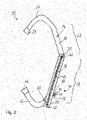
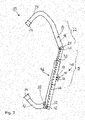
- FIGS. 2 and 3 show a cattle whipping bracket 10, which is shown partially cut open in the region of the straight inner tube section 18 and the outer tube 30.
- the inner pipe section 18 around which the outer pipe 30 is surrounded is indicated with dashed lines.
- bracket elements 14 and 20 are not fixed in their displacement position, but are freely displaceable relative to one another.
- FIG. 3 shows a cattle whipping frame 10 in a shifting position 46 fixed by means of a screwed-in locking screw 50, in which both frame elements 14 and 20 are pulled apart and thus shifted away from one another. Characterized the coil spring 44 is stretched and biased.
- a user pulls the stirrup members 14 and 20 apart far enough to comfortably place the cattle stirrup 10 from the flank 36 to over the spine 26 of the cow 12.
- the bracket elements 14 and 20 are fixed in place by the user by screwing in the locking screw 50 .
- the cattle whipping bracket 10 is placed over the backbone 26 , encompassing the flank 36 of the cow 12 from below.
- the fixed sliding position 46 is released by the user.
- the two bracket elements 14 and 20 are pulled together again by means of a restoring force of the coil spring 44 until the cow 12 restricts such a pulling together with its body.
- the helical spring 44 is correspondingly adapted in terms of its spring force, its extent and its length in connection with the two bracket elements 14 and 20 .
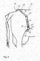
- FIG. 4 shows a state of the cattle whipping bracket 10 attached to and held on the cow 12.
- the two bracket elements 14 and 20 are relative to one another and away from one another by means of their elastic tensioning device 38 movable.
- the bracket elements 14 and 20 are pulled apart, so to speak, by the cow 12 itself or by its movement.
- no undesirably large compressive and tensile forces are exerted on the cow 12 by the cattle whipping bar 10, which has a strong calming effect on the cow 12.
- the cow 12 changes position. It may be that the cattle whipping bracket 10 has to be shorter in its longitudinal extent in order to be held stably on the cow 12 .
- the two bracket elements 14 and 20 are pulled together again by means of the helical spring 44 so that the cattle beating bracket 10 is always held stably on the cow 12 with every movement of the cow 12 .
- the cattle beating bar 10 automatically adapts to the movements of the cow 12 . This allows the cattle whip 10 to always exert its calming effect without being too restrictive for the cow 12 .
Landscapes
- Life Sciences & Earth Sciences (AREA)
- Environmental Sciences (AREA)
- Animal Behavior & Ethology (AREA)
- Zoology (AREA)
- Animal Husbandry (AREA)
- Biodiversity & Conservation Biology (AREA)
- Housing For Livestock And Birds (AREA)
Claims (9)
- Entrave (10) pour empêcher qu'un bétail (12) rue, avec deux éléments d'arceau (14, 20) qui sont déplaçables l'un opposé a l'autre et qui sont adaptés pour fixer l'entrave (10) au bétail (12) entre un flanc (36) et une colonne vertébrale (26) du bétail (12),
caractérisé en ce qe, si l'entrave (10) est attaché au bétail (12), les deux éléments d'arceau (14, 20) sont conçus à cause d'un mouvement du bétail (12) déplaçables l'un opposé à l'autre, et le déplacement des deux éléments d'arceau (14, 20) est conçu en moyen d'un dispositif de tendeur (38) élastique raccordant les deux éléments d'arceau (14, 20). - Entrave selon la revendication 1,
caractérisé en ce qe le dispositif de tendeur (38) est conçu avec un ressort hélicoïdal (44). - Entrave selon la revendication 1 ou 2,
caractérisé en ce que le dispositif de tendeur (38) a une force de tension dimensionnée de telle manière qu'en déplaçant manuellement les deux éléments d'arceau (14, 20) contre la force de tension, une position de déplacement (46) des deux éléments d'arceau (14, 20) peut être atteinte, avec laquelle l'entrave (10) peut être attaché au bétail (12). - Entrave selon une des revendications 1 à 3,
caractérisé en ce que les deux éléments d'arceau (14, 20) peuvent être optionnellement bloqués l'un opposé à l'autre par un dispositif de blocage (48). - Entrave selon la revendication 4,
caractérisé en ce que le dispositif de blocage (48) présente au moins deux niveaux. - Entrave selon la revendication 4,
caractérisé en ce que le dispositif de blocage (48) est conçu variable en continu. - Entrave selon une des revendications 4 à 6,
caractérisé en ce que le dispositif de blocage (48) présente une vis de blocage (50). - Entrave selon une des revendications 4 à 7,
caractérisé en ce que le dispositif de blocage (48) présente une goupille élastique de blocage. - Entrave selon une des revendications 1 à 8,
caractérisé en ce que les deux éléments d'arceau (14, 20) sont conçus tubulaires, en particulier un élément d'arceau (14) est conçu avec un tube intérieur (16) et l'autre élément d'arceau (20) est conçu avec un tube extérieur (30) englobant le tube intérieur (16).
Applications Claiming Priority (1)
| Application Number | Priority Date | Filing Date | Title |
|---|---|---|---|
| DE102017003125.8A DE102017003125A1 (de) | 2017-03-29 | 2017-03-29 | Vieh-Schlagbügel mit zwei Bügelelementen |
Publications (2)
| Publication Number | Publication Date |
|---|---|
| EP3381274A1 EP3381274A1 (fr) | 2018-10-03 |
| EP3381274B1 true EP3381274B1 (fr) | 2022-04-27 |
Family
ID=61832353
Family Applications (1)
| Application Number | Title | Priority Date | Filing Date |
|---|---|---|---|
| EP18164485.7A Active EP3381274B1 (fr) | 2017-03-29 | 2018-03-28 | Arceau de frappe pour animaux d'élevage doté de deux éléments arceau |
Country Status (2)
| Country | Link |
|---|---|
| EP (1) | EP3381274B1 (fr) |
| DE (1) | DE102017003125A1 (fr) |
Families Citing this family (2)
| Publication number | Priority date | Publication date | Assignee | Title |
|---|---|---|---|---|
| CN111407455A (zh) * | 2020-04-17 | 2020-07-14 | 青岛问峰实业有限公司 | 牲畜防踢器 |
| CN119422940B (zh) * | 2025-01-08 | 2025-04-29 | 呼和浩特市艾思网络技术有限公司 | 一种畜牧业用固定架 |
Family Cites Families (6)
| Publication number | Priority date | Publication date | Assignee | Title |
|---|---|---|---|---|
| US546999A (en) * | 1895-10-01 | Milking device | ||
| NL8104218A (nl) * | 1981-09-11 | 1983-04-05 | Albert Van Der Bent | Koespanbeugel of koeklem. |
| EP0868846A3 (fr) * | 1997-03-07 | 1998-11-11 | Stanley Edwards | Dispositif pour empêcher les vaches de ruer |
| NL1013527C2 (nl) * | 1999-11-09 | 2001-05-11 | Metal Inv S Holland B V | Inrichting om te beletten dat dieren met hun achterpoten slaan. |
| KR100701280B1 (ko) * | 2005-06-09 | 2007-04-02 | 대한민국 | 대가축 후지공격 예방기구 |
| RU2613492C1 (ru) * | 2016-04-05 | 2017-03-16 | Федеральное государственное бюджетное образовательное Учреждение высшего образования "Воронежский государственный аграрный университет имени императора Петра 1" (ФГБОУ ВО Воронежский ГАУ) | Устройство для защиты оператора от травм при проведении ветеринарно-санитарных мероприятий |
-
2017
- 2017-03-29 DE DE102017003125.8A patent/DE102017003125A1/de not_active Withdrawn
-
2018
- 2018-03-28 EP EP18164485.7A patent/EP3381274B1/fr active Active
Also Published As
| Publication number | Publication date |
|---|---|
| DE102017003125A1 (de) | 2018-10-04 |
| EP3381274A1 (fr) | 2018-10-03 |
Similar Documents
| Publication | Publication Date | Title |
|---|---|---|
| DE1482482A1 (de) | Einstellvorrichtung an einem Dreipunktgestaenge zum Anbau eines landwirtschaftlichen Geraetes an einen Schlepper | |
| DE1919472A1 (de) | Werkzeug zum Spannen eines einem Gegenstand umgelegten Bandes und zum Verbinden und Abschneiden der Bandenden | |
| DE602004008709T2 (de) | Bügelsäge mit Mechanismus zum Verstellen der Sägeblattspannung | |
| EP3381274B1 (fr) | Arceau de frappe pour animaux d'élevage doté de deux éléments arceau | |
| DE102012100385B4 (de) | Feststellbares Führungselement für längliche flexible Materialien | |
| DE4200771A1 (de) | Wiederoeffenbarer kabelbinder | |
| DE20205797U1 (de) | Halsband | |
| DE1940861C3 (de) | Abschließbarer Schiträger für Kraftfahrzeuge | |
| DE10259679B4 (de) | Hundeleine | |
| EP3395743A1 (fr) | Dispositif de raccourcissement pour une chaîne à maillons | |
| DE202018102324U1 (de) | Oberlippenbremse für Pferde im Klammerstil | |
| CH459876A (de) | Werkzeug zum Spannen und Abschneiden von Bindegurten | |
| DE4301857C1 (de) | Gerät zur Viehgeburtshilfe | |
| EP4165986B1 (fr) | Pince de montage pour transporter des cannes à pêche | |
| DE60303082T2 (de) | Vorrichtung zur Behandlung eines Hinterbeines eines vierbeinigen Tieres | |
| DE3907338C1 (en) | Matrix fixator for dental purposes | |
| DE2722730A1 (de) | Selbstfang-anbindevorrichtung | |
| EP3346936B1 (fr) | Instrument d'insertion de la barre à angle de la barre réglable | |
| AT405226B (de) | Hängevorrichtung für elektrische leitungen | |
| DE124303C (fr) | ||
| EP0392319A2 (fr) | Appareil pour aider à la parturition de bestiaux | |
| EP4066632A1 (fr) | Dispositif de retenue des animaux | |
| EP4670915A1 (fr) | Outil pour détacher une pièce fixe | |
| DE19547386A1 (de) | Vorrichtung zum Verzurren von Containern | |
| DE8412181U1 (de) | Geraet zur viehgeburtshilfe |
Legal Events
| Date | Code | Title | Description |
|---|---|---|---|
| PUAI | Public reference made under article 153(3) epc to a published international application that has entered the european phase |
Free format text: ORIGINAL CODE: 0009012 |
|
| STAA | Information on the status of an ep patent application or granted ep patent |
Free format text: STATUS: THE APPLICATION HAS BEEN PUBLISHED |
|
| AK | Designated contracting states |
Kind code of ref document: A1 Designated state(s): AL AT BE BG CH CY CZ DE DK EE ES FI FR GB GR HR HU IE IS IT LI LT LU LV MC MK MT NL NO PL PT RO RS SE SI SK SM TR |
|
| AX | Request for extension of the european patent |
Extension state: BA ME |
|
| STAA | Information on the status of an ep patent application or granted ep patent |
Free format text: STATUS: REQUEST FOR EXAMINATION WAS MADE |
|
| 17P | Request for examination filed |
Effective date: 20190402 |
|
| RBV | Designated contracting states (corrected) |
Designated state(s): AL AT BE BG CH CY CZ DE DK EE ES FI FR GB GR HR HU IE IS IT LI LT LU LV MC MK MT NL NO PL PT RO RS SE SI SK SM TR |
|
| GRAP | Despatch of communication of intention to grant a patent |
Free format text: ORIGINAL CODE: EPIDOSNIGR1 |
|
| STAA | Information on the status of an ep patent application or granted ep patent |
Free format text: STATUS: GRANT OF PATENT IS INTENDED |
|
| INTG | Intention to grant announced |
Effective date: 20211202 |
|
| GRAS | Grant fee paid |
Free format text: ORIGINAL CODE: EPIDOSNIGR3 |
|
| GRAA | (expected) grant |
Free format text: ORIGINAL CODE: 0009210 |
|
| STAA | Information on the status of an ep patent application or granted ep patent |
Free format text: STATUS: THE PATENT HAS BEEN GRANTED |
|
| AK | Designated contracting states |
Kind code of ref document: B1 Designated state(s): AL AT BE BG CH CY CZ DE DK EE ES FI FR GB GR HR HU IE IS IT LI LT LU LV MC MK MT NL NO PL PT RO RS SE SI SK SM TR |
|
| REG | Reference to a national code |
Ref country code: GB Ref legal event code: FG4D Free format text: NOT ENGLISH |
|
| REG | Reference to a national code |
Ref country code: CH Ref legal event code: EP |
|
| REG | Reference to a national code |
Ref country code: AT Ref legal event code: REF Ref document number: 1486219 Country of ref document: AT Kind code of ref document: T Effective date: 20220515 |
|
| REG | Reference to a national code |
Ref country code: DE Ref legal event code: R096 Ref document number: 502018009474 Country of ref document: DE |
|
| REG | Reference to a national code |
Ref country code: IE Ref legal event code: FG4D Free format text: LANGUAGE OF EP DOCUMENT: GERMAN |
|
| REG | Reference to a national code |
Ref country code: LT Ref legal event code: MG9D |
|
| REG | Reference to a national code |
Ref country code: NL Ref legal event code: MP Effective date: 20220427 |
|
| PG25 | Lapsed in a contracting state [announced via postgrant information from national office to epo] |
Ref country code: NL Free format text: LAPSE BECAUSE OF FAILURE TO SUBMIT A TRANSLATION OF THE DESCRIPTION OR TO PAY THE FEE WITHIN THE PRESCRIBED TIME-LIMIT Effective date: 20220427 |
|
| PG25 | Lapsed in a contracting state [announced via postgrant information from national office to epo] |
Ref country code: SE Free format text: LAPSE BECAUSE OF FAILURE TO SUBMIT A TRANSLATION OF THE DESCRIPTION OR TO PAY THE FEE WITHIN THE PRESCRIBED TIME-LIMIT Effective date: 20220427 Ref country code: PT Free format text: LAPSE BECAUSE OF FAILURE TO SUBMIT A TRANSLATION OF THE DESCRIPTION OR TO PAY THE FEE WITHIN THE PRESCRIBED TIME-LIMIT Effective date: 20220829 Ref country code: NO Free format text: LAPSE BECAUSE OF FAILURE TO SUBMIT A TRANSLATION OF THE DESCRIPTION OR TO PAY THE FEE WITHIN THE PRESCRIBED TIME-LIMIT Effective date: 20220727 Ref country code: LT Free format text: LAPSE BECAUSE OF FAILURE TO SUBMIT A TRANSLATION OF THE DESCRIPTION OR TO PAY THE FEE WITHIN THE PRESCRIBED TIME-LIMIT Effective date: 20220427 Ref country code: HR Free format text: LAPSE BECAUSE OF FAILURE TO SUBMIT A TRANSLATION OF THE DESCRIPTION OR TO PAY THE FEE WITHIN THE PRESCRIBED TIME-LIMIT Effective date: 20220427 Ref country code: GR Free format text: LAPSE BECAUSE OF FAILURE TO SUBMIT A TRANSLATION OF THE DESCRIPTION OR TO PAY THE FEE WITHIN THE PRESCRIBED TIME-LIMIT Effective date: 20220728 Ref country code: FI Free format text: LAPSE BECAUSE OF FAILURE TO SUBMIT A TRANSLATION OF THE DESCRIPTION OR TO PAY THE FEE WITHIN THE PRESCRIBED TIME-LIMIT Effective date: 20220427 Ref country code: ES Free format text: LAPSE BECAUSE OF FAILURE TO SUBMIT A TRANSLATION OF THE DESCRIPTION OR TO PAY THE FEE WITHIN THE PRESCRIBED TIME-LIMIT Effective date: 20220427 Ref country code: BG Free format text: LAPSE BECAUSE OF FAILURE TO SUBMIT A TRANSLATION OF THE DESCRIPTION OR TO PAY THE FEE WITHIN THE PRESCRIBED TIME-LIMIT Effective date: 20220727 |
|
| PG25 | Lapsed in a contracting state [announced via postgrant information from national office to epo] |
Ref country code: RS Free format text: LAPSE BECAUSE OF FAILURE TO SUBMIT A TRANSLATION OF THE DESCRIPTION OR TO PAY THE FEE WITHIN THE PRESCRIBED TIME-LIMIT Effective date: 20220427 Ref country code: PL Free format text: LAPSE BECAUSE OF FAILURE TO SUBMIT A TRANSLATION OF THE DESCRIPTION OR TO PAY THE FEE WITHIN THE PRESCRIBED TIME-LIMIT Effective date: 20220427 Ref country code: LV Free format text: LAPSE BECAUSE OF FAILURE TO SUBMIT A TRANSLATION OF THE DESCRIPTION OR TO PAY THE FEE WITHIN THE PRESCRIBED TIME-LIMIT Effective date: 20220427 Ref country code: IS Free format text: LAPSE BECAUSE OF FAILURE TO SUBMIT A TRANSLATION OF THE DESCRIPTION OR TO PAY THE FEE WITHIN THE PRESCRIBED TIME-LIMIT Effective date: 20220827 |
|
| REG | Reference to a national code |
Ref country code: DE Ref legal event code: R097 Ref document number: 502018009474 Country of ref document: DE |
|
| PG25 | Lapsed in a contracting state [announced via postgrant information from national office to epo] |
Ref country code: SM Free format text: LAPSE BECAUSE OF FAILURE TO SUBMIT A TRANSLATION OF THE DESCRIPTION OR TO PAY THE FEE WITHIN THE PRESCRIBED TIME-LIMIT Effective date: 20220427 Ref country code: SK Free format text: LAPSE BECAUSE OF FAILURE TO SUBMIT A TRANSLATION OF THE DESCRIPTION OR TO PAY THE FEE WITHIN THE PRESCRIBED TIME-LIMIT Effective date: 20220427 Ref country code: RO Free format text: LAPSE BECAUSE OF FAILURE TO SUBMIT A TRANSLATION OF THE DESCRIPTION OR TO PAY THE FEE WITHIN THE PRESCRIBED TIME-LIMIT Effective date: 20220427 Ref country code: EE Free format text: LAPSE BECAUSE OF FAILURE TO SUBMIT A TRANSLATION OF THE DESCRIPTION OR TO PAY THE FEE WITHIN THE PRESCRIBED TIME-LIMIT Effective date: 20220427 Ref country code: DK Free format text: LAPSE BECAUSE OF FAILURE TO SUBMIT A TRANSLATION OF THE DESCRIPTION OR TO PAY THE FEE WITHIN THE PRESCRIBED TIME-LIMIT Effective date: 20220427 Ref country code: CZ Free format text: LAPSE BECAUSE OF FAILURE TO SUBMIT A TRANSLATION OF THE DESCRIPTION OR TO PAY THE FEE WITHIN THE PRESCRIBED TIME-LIMIT Effective date: 20220427 |
|
| PLBE | No opposition filed within time limit |
Free format text: ORIGINAL CODE: 0009261 |
|
| STAA | Information on the status of an ep patent application or granted ep patent |
Free format text: STATUS: NO OPPOSITION FILED WITHIN TIME LIMIT |
|
| PG25 | Lapsed in a contracting state [announced via postgrant information from national office to epo] |
Ref country code: AL Free format text: LAPSE BECAUSE OF FAILURE TO SUBMIT A TRANSLATION OF THE DESCRIPTION OR TO PAY THE FEE WITHIN THE PRESCRIBED TIME-LIMIT Effective date: 20220427 |
|
| 26N | No opposition filed |
Effective date: 20230130 |
|
| PG25 | Lapsed in a contracting state [announced via postgrant information from national office to epo] |
Ref country code: SI Free format text: LAPSE BECAUSE OF FAILURE TO SUBMIT A TRANSLATION OF THE DESCRIPTION OR TO PAY THE FEE WITHIN THE PRESCRIBED TIME-LIMIT Effective date: 20220427 |
|
| PG25 | Lapsed in a contracting state [announced via postgrant information from national office to epo] |
Ref country code: MC Free format text: LAPSE BECAUSE OF FAILURE TO SUBMIT A TRANSLATION OF THE DESCRIPTION OR TO PAY THE FEE WITHIN THE PRESCRIBED TIME-LIMIT Effective date: 20220427 |
|
| REG | Reference to a national code |
Ref country code: CH Ref legal event code: PL |
|
| GBPC | Gb: european patent ceased through non-payment of renewal fee |
Effective date: 20230328 |
|
| REG | Reference to a national code |
Ref country code: BE Ref legal event code: MM Effective date: 20230331 |
|
| PG25 | Lapsed in a contracting state [announced via postgrant information from national office to epo] |
Ref country code: LU Free format text: LAPSE BECAUSE OF NON-PAYMENT OF DUE FEES Effective date: 20230328 |
|
| REG | Reference to a national code |
Ref country code: IE Ref legal event code: MM4A |
|
| PG25 | Lapsed in a contracting state [announced via postgrant information from national office to epo] |
Ref country code: GB Free format text: LAPSE BECAUSE OF NON-PAYMENT OF DUE FEES Effective date: 20230328 |
|
| PG25 | Lapsed in a contracting state [announced via postgrant information from national office to epo] |
Ref country code: LI Free format text: LAPSE BECAUSE OF NON-PAYMENT OF DUE FEES Effective date: 20230331 Ref country code: IT Free format text: LAPSE BECAUSE OF FAILURE TO SUBMIT A TRANSLATION OF THE DESCRIPTION OR TO PAY THE FEE WITHIN THE PRESCRIBED TIME-LIMIT Effective date: 20220427 Ref country code: IE Free format text: LAPSE BECAUSE OF NON-PAYMENT OF DUE FEES Effective date: 20230328 Ref country code: GB Free format text: LAPSE BECAUSE OF NON-PAYMENT OF DUE FEES Effective date: 20230328 Ref country code: FR Free format text: LAPSE BECAUSE OF NON-PAYMENT OF DUE FEES Effective date: 20230331 Ref country code: CH Free format text: LAPSE BECAUSE OF NON-PAYMENT OF DUE FEES Effective date: 20230331 |
|
| PG25 | Lapsed in a contracting state [announced via postgrant information from national office to epo] |
Ref country code: BE Free format text: LAPSE BECAUSE OF NON-PAYMENT OF DUE FEES Effective date: 20230331 |
|
| PG25 | Lapsed in a contracting state [announced via postgrant information from national office to epo] |
Ref country code: BG Free format text: LAPSE BECAUSE OF FAILURE TO SUBMIT A TRANSLATION OF THE DESCRIPTION OR TO PAY THE FEE WITHIN THE PRESCRIBED TIME-LIMIT Effective date: 20220427 |
|
| PG25 | Lapsed in a contracting state [announced via postgrant information from national office to epo] |
Ref country code: BG Free format text: LAPSE BECAUSE OF FAILURE TO SUBMIT A TRANSLATION OF THE DESCRIPTION OR TO PAY THE FEE WITHIN THE PRESCRIBED TIME-LIMIT Effective date: 20220427 |
|
| PGFP | Annual fee paid to national office [announced via postgrant information from national office to epo] |
Ref country code: AT Payment date: 20250311 Year of fee payment: 8 |
|
| PG25 | Lapsed in a contracting state [announced via postgrant information from national office to epo] |
Ref country code: CY Free format text: LAPSE BECAUSE OF FAILURE TO SUBMIT A TRANSLATION OF THE DESCRIPTION OR TO PAY THE FEE WITHIN THE PRESCRIBED TIME-LIMIT; INVALID AB INITIO Effective date: 20180328 |
|
| PG25 | Lapsed in a contracting state [announced via postgrant information from national office to epo] |
Ref country code: HU Free format text: LAPSE BECAUSE OF FAILURE TO SUBMIT A TRANSLATION OF THE DESCRIPTION OR TO PAY THE FEE WITHIN THE PRESCRIBED TIME-LIMIT; INVALID AB INITIO Effective date: 20180328 |
|
| PG25 | Lapsed in a contracting state [announced via postgrant information from national office to epo] |
Ref country code: TR Free format text: LAPSE BECAUSE OF FAILURE TO SUBMIT A TRANSLATION OF THE DESCRIPTION OR TO PAY THE FEE WITHIN THE PRESCRIBED TIME-LIMIT Effective date: 20220427 |
|
| PGFP | Annual fee paid to national office [announced via postgrant information from national office to epo] |
Ref country code: DE Payment date: 20260331 Year of fee payment: 9 |