EP3381376A2 - Système rétracteur chirurgical doté d'un rétracteur et d'un extracteur - Google Patents
Système rétracteur chirurgical doté d'un rétracteur et d'un extracteur Download PDFInfo
- Publication number
- EP3381376A2 EP3381376A2 EP18164843.7A EP18164843A EP3381376A2 EP 3381376 A2 EP3381376 A2 EP 3381376A2 EP 18164843 A EP18164843 A EP 18164843A EP 3381376 A2 EP3381376 A2 EP 3381376A2
- Authority
- EP
- European Patent Office
- Prior art keywords
- retractor
- extractor
- surgical
- section
- surgical instrument
- Prior art date
- Legal status (The legal status is an assumption and is not a legal conclusion. Google has not performed a legal analysis and makes no representation as to the accuracy of the status listed.)
- Granted
Links
Images
Classifications
-
- A—HUMAN NECESSITIES
- A61—MEDICAL OR VETERINARY SCIENCE; HYGIENE
- A61B—DIAGNOSIS; SURGERY; IDENTIFICATION
- A61B17/00—Surgical instruments, devices or methods
- A61B17/02—Surgical instruments, devices or methods for holding wounds open, e.g. retractors; Tractors
- A61B17/0218—Surgical instruments, devices or methods for holding wounds open, e.g. retractors; Tractors for minimally invasive surgery
-
- A—HUMAN NECESSITIES
- A61—MEDICAL OR VETERINARY SCIENCE; HYGIENE
- A61B—DIAGNOSIS; SURGERY; IDENTIFICATION
- A61B17/00—Surgical instruments, devices or methods
- A61B17/02—Surgical instruments, devices or methods for holding wounds open, e.g. retractors; Tractors
- A61B17/025—Joint distractors
-
- A—HUMAN NECESSITIES
- A61—MEDICAL OR VETERINARY SCIENCE; HYGIENE
- A61B—DIAGNOSIS; SURGERY; IDENTIFICATION
- A61B17/00—Surgical instruments, devices or methods
- A61B2017/0023—Surgical instruments, devices or methods disposable
-
- A—HUMAN NECESSITIES
- A61—MEDICAL OR VETERINARY SCIENCE; HYGIENE
- A61B—DIAGNOSIS; SURGERY; IDENTIFICATION
- A61B17/00—Surgical instruments, devices or methods
- A61B2017/00477—Coupling
-
- A—HUMAN NECESSITIES
- A61—MEDICAL OR VETERINARY SCIENCE; HYGIENE
- A61B—DIAGNOSIS; SURGERY; IDENTIFICATION
- A61B17/00—Surgical instruments, devices or methods
- A61B17/02—Surgical instruments, devices or methods for holding wounds open, e.g. retractors; Tractors
- A61B17/0218—Surgical instruments, devices or methods for holding wounds open, e.g. retractors; Tractors for minimally invasive surgery
- A61B2017/0225—Surgical instruments, devices or methods for holding wounds open, e.g. retractors; Tractors for minimally invasive surgery flexible, e.g. fabrics, meshes, or membranes
-
- A—HUMAN NECESSITIES
- A61—MEDICAL OR VETERINARY SCIENCE; HYGIENE
- A61B—DIAGNOSIS; SURGERY; IDENTIFICATION
- A61B90/00—Instruments, implements or accessories specially adapted for surgery or diagnosis and not covered by any of the groups A61B1/00 - A61B50/00, e.g. for luxation treatment or for protecting wound edges
- A61B90/03—Automatic limiting or abutting means, e.g. for safety
- A61B2090/037—Automatic limiting or abutting means, e.g. for safety with a frangible part, e.g. by reduced diameter
-
- A—HUMAN NECESSITIES
- A61—MEDICAL OR VETERINARY SCIENCE; HYGIENE
- A61F—FILTERS IMPLANTABLE INTO BLOOD VESSELS; PROSTHESES; DEVICES PROVIDING PATENCY TO, OR PREVENTING COLLAPSING OF, TUBULAR STRUCTURES OF THE BODY, e.g. STENTS; ORTHOPAEDIC, NURSING OR CONTRACEPTIVE DEVICES; FOMENTATION; TREATMENT OR PROTECTION OF EYES OR EARS; BANDAGES, DRESSINGS OR ABSORBENT PADS; FIRST-AID KITS
- A61F2230/00—Geometry of prostheses classified in groups A61F2/00 - A61F2/26 or A61F2/82 or A61F9/00 or A61F11/00 or subgroups thereof
- A61F2230/0063—Three-dimensional shapes
- A61F2230/0069—Three-dimensional shapes cylindrical
Definitions
- the present invention relates to a surgical retractor system according to the preamble of claim 1.
- This has a retractor and an extractor.
- the retractor is particularly stented and additionally prepared to perform a distractor function.
- the invention also relates to a surgical instrument for releasing a distractor and / or a retractor according to the preamble of claim 9.
- Such a surgical instrument may also be referred to as an extractor unit.
- a surgical retractor system with a retractor and an extractor is, firstly, capable of keeping an operative field / incision open.
- the retractor is used from outside a patient to be treated in the surgical field and spaced from the retractor spreading / expansion sections spaced from each other.
- connective and / or muscle tissue is forced apart and thus expanded the surgical field.
- the at least one extractor of the surgical retractor system or system is configured to re-compress the force-biased expanders at the end of an operation or surgical procedure to allow release of the retractor from the patient.
- a distractor is generally a surgical instrument for the controlled spreading / pulling apart of body structures by external mechanical action (distraction).
- Distractors are used, for example, in trauma surgery, orthopedics and maxillofacial surgery for the extension treatment of bones.
- Retractors are known from the prior art, which also fulfill a distractor function in addition to the retractor.
- Aesculap AG DE 10 2015 100932 A1
- a stent retractor / distractor so a retractor with a stent structure.
- This has a radially flexible expandable, tubular shell, which is divided in the circumferential direction in at least two sections, namely a stiffening portion and a widening portion with mutually different radial flexibility, which are integrally connected to each other fabric. This makes it possible to adapt the stent retractor / distractor to a patient-side opening.
- a compression forceps is disclosed in the aforementioned application. This compresses the stent retractor / distractor until it is releasable.
- a compression forceps is usually available in operating theaters and goes through a complex disinfection cycle after each use.
- a disadvantage of this prior art is, first, that the destructive effect of the compression forceps on the stent retractor / distractor varies from case to case, which often results in a time-consuming and unpredictable release operation of the retractor from the patient-side opening. Furthermore, the use of the compression forceps after each use entails a costly and time-consuming disinfection process, which affects the economics of the retractor system.
- Another object of the invention is to provide a retractor or a surgical instrument that is inexpensive to manufacture and easy to disinfect and that is robust in use and almost eliminates incorrect operation.
- the subject of the invention is firstly a surgical retractor system with a substantially tubular retractor which preferably has a plurality of segments in the axial direction. These are then irreversibly separable from each other to make a length adjustment of the retractor, whereby the retractor is flexible ausgestaltetbar in its longitudinal direction. At least one of the segments is further preferably divided in the circumferential direction into at least one expansion section / element and a plate section / extractor engagement section. These two sections then have a different radial flexibility relative to one another and are preferably connected to one another in a material-integral manner, so that a plastic radial expansion of the retractor is made possible.
- the radial widening of the retractor serves, as mentioned at the beginning, on the one hand to keep open the surgical field.
- the distraction which can be carried out by the retractor according to the invention can also be realized if necessary.
- the surgical retractor system exhibits Also, at least one extractor / compression instrument / compression tool / compression mechanism operable to cause a radial radial expansion of the retractor opposite the radial expansion of the retractor. This radial restriction causes destruction of the retractor and allows it to be removed from the opening.
- the at least one extractor is prepared to cooperate with the retractor, preferably with its at least one plate section, for a torsion moment entry in order to obtain the radial narrowing of the retractor.
- the retractor-side plate section There is thus a kind of matrix-male relationship between the retractor-side plate section and the extractor. If, therefore, the plate section is modified in terms of its geometry, the extractor must also be adapted to this change.
- the extractor is prepared to force the plastic radial narrowing of the retractor by means of a torsional moment acting on the retractor.
- the torsional moment causes for the first a kind of winding of the retractor on the extractor, which entails a reliable radial / diameter constriction.
- the torsional deformation according to the invention can be realized by means of a positive connection between the extractor and the retractor. Since sufficient care is taken with the respective components to ensure sufficient rigidity, unintentional release of the positive locking is not possible. Thus, the safety of the retractor system is increased because about a slippage of the tool, as occurs frequently in compression tongs of the prior art, is excluded.
- the extractor has a handle portion and an operative portion with a slot which is placed on the plate portion of the retractor such that it engages around its radially inwardly facing surface and on its radially outwardly facing surface, the reliability of the positive connection is increased ,
- a second extractor is prepared to cooperate with a second plate portion of the same retractor such that two extractors cause a radial narrowing of the one retractor.
- the use of a second extractor makes it possible to create a comfortable deformation with two hands.
- the second extractor is preferably designed identical to the first extractor. Thus, the production costs are lowered.
- the second extractor allows the extraction of the extractor with a simple geometry (since two extractors with a simple geometry produce the same effect as an extractor with a complex geometry).
- the production costs are further reduced, which makes it possible, in addition to the retractor and the extractor and thus form the entire retractor system as a disposable / disposable product according to the single-use concept.
- the surgical retractor system is characterized in that the two extractors are prepared to force a winding / rolling / twisting / bending of the retractor onto the extractors by means of an opposite rotational movement.
- the application of an opposite rotational movement to the retractor induces a torsional moment similar in function to that of a sardine can.
- a predetermined breaking point is arranged to cause buckling of the retractor at the predetermined breaking point upon application of the torsional moment. This guarantees that the retractor will follow a predetermined kink / break line.
- the inventive concept also includes the idea that the predetermined breaking point extends at an angle to the axial direction in order to produce a fan-shaped radial narrowing. Such a predetermined breaking point increases the first operational reliability, as is respected in the corresponding breaklines on a round shape, on the other hand, it allows the treating surgeon a comfortable radial narrowing. The tedious on the retractor often tedious in the art is thus avoided.
- a surgical instrument for releasing a distractor or also a retractor from an opening kept open by the distractor / retractor, preferably on the patient side.
- the surgical instrument which can also be referred to as extractor unit, has at least one handle section defining a handle longitudinal axis and at least one effective section defining an effective longitudinal axis, which are coupled to one another via a connecting section / link.
- the connecting section arranges the grip section and the active section in relation to one another in such a way that the handle longitudinal axis and the active longitudinal axis run at an angle to one another, preferably at an angle between 60 ° and 140 °, particularly preferably 90 °.
- the angle between the handle longitudinal axis and the active longitudinal axis is described here as wandering starting from the effective longitudinal axis in the direction of the handle longitudinal axis. At an angle of 60 °, the connecting section thus defines an acute angle.
- the handle portion of the surgical instrument over the entire length along the handle longitudinal axis has a substantially circular and substantially constant cross-section and the effective portion over the entire length along the effective longitudinal axis has a substantially circular and substantially constant cross-section
- the diameter of the grip section preferably corresponds to the diameter of the active section. Deviations of up to 10% of the diameters from each other are also covered by the inventive idea.
- the surgical instrument preferably has at its operative portion a longitudinal slot which extends along the longitudinal axis of action and divides the operative portion into two circumferentially separated legs which are preferably equal in size or at least as large in size, that is, their area occupied in cross-section.
- the legs are in this case both in their length, as well as in their cross-sectional area substantially the same size.
- the longitudinal slot extends in a plane in which the active longitudinal axis also extends.
- first leg of the knit section is prepared to contact the retractor radially outward / laterally and the other, second leg of the knit section is prepared to contact the retractor radially inward / medially, an efficient, error-free placement of the extractor unit is achieved guaranteed the retractor.
- the surgical instrument is composed of two identical angled extractors, whereby the comfort and operating accuracy is increased because the caused by the surgical instrument plastic deformation of the retractor can be initiated by both hands of a surgeon, after which less force is applied in the individual hand.
- the precision of the surgical instrument is also increased.
- a further advantageous embodiment is characterized in that the connecting portion with respect to the length of its angled course, so the amount of the length of the connecting portion, if one would "straighten” this, compared to the length of the effective portion along the longitudinal axis and the length of the effective length Handle portion along the handle longitudinal axis.
- the at least one extractor or the surgical instrument as a blank in cross-section preferably round solid or hollow profile rod basis whose connecting portion is formed by forming, in particular by bending, of the rod and its effective portion at least one by a machining production step, such as sawing or grinding, or even by a punching or laser step generated longitudinal slot which divides the distal end of the rod in the region of the active portion in at least two preferably equal legs, whereby the surgical instrument is suitable as a one-way component.
- a simple geometry is realized with economically producible components, which are associated in the purchase with such low costs that they can be used while avoiding a disinfection process as a disposable product / disposable product / single-use product.
- an advantageous embodiment aims at designing the at least one extractor as a disposable component in order to avoid a disinfection process.
- the invention can be described such that two slotted extractors from the outside / distal form-fitting manner to the plate sections, which give the radially flexible retractor a stiffness, can be placed. After placement, it is possible to rotate the two extractors against each other so that they deform the retractor, which rotates due to the positive connection with the rotation of the extractor, and so reduce in diameter that it is easily detachable from its position.
- the at least one extractor on the retractor such that a tensile force can also be transmitted to it.
- the tensile force with the torsional moment is to be connected in series in order first to produce a tubular shape by means of the tensile force from an approximate funnel shape of the retractor, before it is rolled up by means of the torsional moment.
- a retractor system with a retractor stent ie a retractor with a stent structure
- a retractor system with a retractor stent which is adapted for use as a retractor.
- the retractor stent firstly has the property of being freely deformable in the radial direction (eg round, oval, etc.), while at the same time retaining sufficient rigidity to provide tissue in keep pressed apart state.
- a minimally invasive approach for example in the form of a lumbar, thoracic, and / or cervical spinal access can be created. Cranial applications are also possible.
- the expansion sections serve to be able to change the diameter of the retractor stent, whereas the plate sections / stiffening sections increase the stent's resistance to external radial forces at least in certain radial directions and at the same time provide a defined contact surface for the extractor.
- the retractor stent as a distractor instrument, alternatively or in addition to its retraction function, since its resistance forces against radially acting compressing forces, which can be achieved in principle via the stiffening sections, are sufficient to keep bones apart as well.
- the preferably fabric integral design of the retractor stent a simple and fast production, for example by laser or water cutting of metal sheets, is possible.
- the wall structure (shell) of the retractor stent is circumferentially divided into four sections, two of which are designed with substantially equal flexibility as plate sections / stiffening sections and the two further are designed with substantially equal flexibility as flare sections, for which Both plate sections / stiffening sections at least in the circumferential direction and preferably also in the axial direction have a higher rigidity than the two expansion sections.
- the retractor stent can be expanded with simple aids, such as, for example, a dilatation balloon or a speculum or a Langenbeck hook, preferably evenly (symmetrically) or also ovally.
- the two sections can also be arranged diametrically opposite each with the same flexibility.
- the segments of the retractor stent are coupled to one another via axial connecting elements / webs with preferably higher rigidity, which further preferably form predetermined breaking points for segment-wise length reduction.
- This refinement ensures that the retractor stent essentially only expands radially under an internal pressure load.
- the stent is easily adaptable in length to its intended location on the patient's body.
- the functioning of the extractor according to the invention consequently follows that mode of operation of an opening device of a generally known can.
- a take-up rod having a longitudinal slot into which a tab may be inserted on a can lid to be withdrawn.
- the take-up rod is then rotated on a handle formed thereon about its longitudinal axis, the can lid wraps on the take-up rod and thus releases the can access.
- the present invention takes advantage of this principle by having the inventive extractor / extractor unit / surgical instrument at least one such Aufwickelstab as an extractor trained thereon handle (section) or lever with the tubular / sleeve-shaped retractor / stent or its wall so in (linear) form fit can be brought (for example via a longitudinal slot on the take-up rod or a radially projecting driving pin) to transmit a registered via the lever on the take-up rod torque about its longitudinal axis on the wall of the retractor / stent and so buckling and winding the wall in retractor longitudinal direction.
- the inventive extractor / extractor unit / surgical instrument at least one such Aufwickelstab as an extractor trained thereon handle (section) or lever with the tubular / sleeve-shaped retractor / stent or its wall so in (linear) form fit can be brought (for example via a longitudinal slot on the take-up rod or a radially projecting driving pin) to transmit a registered via the
- the Aufwickelstäbe can also be splayed at the handles / levers apart, so that the retractor / stent by means of the extractor unit according to the invention radially can be expanded.
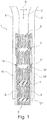
- Fig. 1 shows a surgical retractor system 1 with a retractor 2 and two extractors 6, 6 ', which may also be considered as an extractor unit 6, 6' or generally as a surgical instrument. Of the extractors 6, 6 ', only one active section 9, namely the take-up rod, is shown. With respect to a grip portion 10 of the extractors 6, 6 'be on Fig. 2 directed.
- the retractor 2 is in the longitudinal / axial direction, which is indicated by an arrow 7, divided into a plurality of segments 3, 3 ', 3 ", 3"'.
- the respective segments 3, 3 ', 3 ", 3'” are designed identically in their structure.
- the segment-like configuration in the axial direction allows a separation of individual segments 3, 3 ', 3 ", 3'” from each other, whereby a length adjustment of the retractor 2 can be realized.
- the in Fig. 1 is indicated by the arrow 8, the retractor 2 per segment 3, 3 ', 3 ", 3'" in each case two widening sections / spreading sections 4, of which in the view in Fig. 1 only one is visible, and two plate sections 5, 5 'subdivided.
- the widening portion 4 and the plate portion 5, 5 ' have a different radial flexibility.
- the expansion portion 4 is plastically deformable by means of a stent-like structure, which in the present example is formed over a waveform with a high amplitude compared to its frequency, which allows a radial expansion of the diameter of the tubular retractor 2.
- the expansion portions 4 and the plate portions 5, 5 ' are arranged diametrically opposite to each other, resulting in a mutual arrangement of mutually different sections.
- the retractor system 1 ensures sufficient robustness of the retractor 2. This is required, on the one hand, to realize the initially mentioned distractor function by the retractor 2 and, on the other hand, by a starting point / form a coupling point for the extractors 6, 6 '.
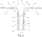
- Fig. 2 the extractors 6, 6 'are off Fig. 1 presented for yourself.
- the aforementioned active section / take-up rod 9 of the extractor 6, or the active section / take-up rod 9 'of the extractor 6' is angled by approximately 90 ° from the handle section 10, 10 ', which forms a lever in the present case.
- the 90 ° here refer to the angle between a longitudinal axis of action 20, 20 ', which represents the longitudinal axis of the active portion 9, 9', and a handle longitudinal axis 21, 21 ', which is analogous to the longitudinal axis of the handle portion 10, 10'.
- the illustrated 90 ° are not meant to be limiting.
- the intermediate section between the active section 9, 9 'and the grip section 10, 10' is realized by a connecting section 22, 22 '.
- the connecting portion 22, 22 ' is preferably realized by means of a forming process.
- the surgical instrument / extractor 6 in the raw state is a rod of uniform diameter, which is first deformed in the region of the connecting portion 22, 22 'by the desired angular span, before or Alternatively, after the longitudinal slot is about cutting in the active section 9, 9 'is introduced / was.
- the connecting section 22, 22 ' is small in its length along the longitudinal axis bent in it compared with the active section 9, 9' and with the handle portion 10, 10 '.
- the longitudinal slot 11, 11 ' preferably extends through the cross-sectional center of the active portion 9, 9'.
- the slot 11, 11 ' is dimensioned such that it can be put over / onto the plate section 5, 5' in the longitudinal direction of the retractor / stent. That is to say the slot width on the extractor 6, 6 'permits insertion of the retractor wall in the retractor longitudinal direction 7.
- the retractor wall is preferably composed in the circumferential direction of the at least one widening section 4 and the at least one plate section 5, 5'.
- the diameter 12, 12 'of the active section 9, 9' preferably corresponds essentially to that of the diameter 13, 13 'grip section 10, 10' and is significantly smaller than the diameter of the retractor / stent.
- the uniformity of the diameter is a consequence of the fact that the extractor 6 in the raw state, as described above, is preferably a rod.
- the handle portion 10, 10 ' also has no ergonomic features.
- the extractor 6, 6 ' is an economically producible, uncomplicated rod component, which enables the surgical retractor system 1 to realize a single-use concept.
- a slot length 14, 14 'of the slot 11, 11' is prepared to exceed the length in the axial direction 7 of at least three segments 3, 3 ', 3 ", thus allowing sufficient force and torque transmission capability of the extractor 6, 6
- a slot bottom 15, 15 'of the slot 11, 11' is designed such that it represents a stop for the one (proximal) front side of the retractor 2.
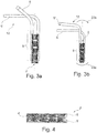
- the radial narrowing of the retractor 2 is represented by the extractors 6, 6 '.
- a relative rotation of the two extractors 6, 6 ' has taken place relative to one another about their respective longitudinal axes, resulting in a plastic deformation in the form of a radial narrowing of the retractor.
- the retractor 2 has been acted upon by the extractors 6, 6 'by means of a torsional moment, which leads to a winding / rolling up / twisting / "crumbling" of the retractor 2 or its wall.
- the torsional moment is indicated by the two arrows 23a and 23b, which realize an opposite rotation and thus a torsion about the longitudinal axis of the retractor 2, which for reasons of perspective not undoubtedly from the schematic illustration in FIG Fig. 3b evident.
- the distal portion of the retractor 2 is experiencing a moment in the first direction (such as via its anchorage in the patient-side opening)
- the proximal portion of the retractor is momentarily acted upon by the extractor 6, 6 'in the second, other direction (FIG. 23b ). This leads to the radial narrowing of the retractor 2 according to the invention.
- Fig. 4 the retractor 2 is shown in the radially narrowed state. So he is from the extractors in Fig. 3a, 3b so plastically deformed that the plate sections 5, 5 'abut each other. The expansion portions 4 have also deformed. The in Fig. 4 shown rolled / wound retractor is easily removed from a patient-side opening.
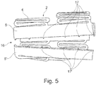
- Fig. 5 shows a retractor 2 in another embodiment.
- a predetermined breaking point 16 is provided between the plate sections 5, 5 '.
- the predetermined breaking point 16 is realized via individual projections 17, 17 ', which are formed by the respective plate section 5, 5'.
- the projections 17, 17 ' which are arranged at the same height, in each case cohesively in contact.
- the retractor off Fig. 5 is already deformed by here not shown extractors 6, 6 ', which is recognizable at the severed breaking point 16.
- the retractor 2 has a tubular or tubular shape, wherein the peripheral portions with mutually identical / similar rigidities are diametrically opposed to each other.
- the retractor 2 is also formed in one piece, i. the individual peripheral sections are materially interconnected.
- the retractor 2 has essentially a wall structure, which is taken over by a standard vascular stent (such as the Coroflex Aesculap AG) in outline.
- a standard vascular stent such as the Coroflex Aesculap AG
- the retractor 2 is formed at least in the region of its widening sections (widening elements) 4 from a number of axially spaced, preferably parallel bands which extend serpentine or accordion-shaped in the circumferential direction and thus form flexible expansion reserves in the radial direction in the area of their accordion form ,
- stiffer passage sections (stiffening sections / plate sections) 5, 5 ' viewed in the circumferential direction, are arranged alternately between the two expansion sections 4.
- the stiffening sections (stiffening elements) 5, 5 ' are formed by substantially closed, preferably rectangular plate sections, which are seen in their basic shape in the axial direction trough or trough-like arched and are intended to expand not or only slightly radially.
- the stiffening sections 5, 5 ' are also used to form a point of application for the extractor 6, 6'. The aim here is to place as many functionalities as possible in the geometry of the wall structure.
- the retractor 2 As a material for the retractor 2 according to the invention steel, titanium or plastic can be used, wherein a plastic part is preferably produced by injection molding. Furthermore, the retractor 2 can be deburred after cutting the wall profiles, for example by electropolishing. Furthermore, in order to improve the photometric reflection properties, for example under microscope applications, the surface of the remaining structures can also be matted or coated.
Landscapes
- Health & Medical Sciences (AREA)
- Life Sciences & Earth Sciences (AREA)
- Surgery (AREA)
- Biomedical Technology (AREA)
- Engineering & Computer Science (AREA)
- Veterinary Medicine (AREA)
- Heart & Thoracic Surgery (AREA)
- Animal Behavior & Ethology (AREA)
- General Health & Medical Sciences (AREA)
- Public Health (AREA)
- Medical Informatics (AREA)
- Molecular Biology (AREA)
- Nuclear Medicine, Radiotherapy & Molecular Imaging (AREA)
- Surgical Instruments (AREA)
- Cardiology (AREA)
- Oral & Maxillofacial Surgery (AREA)
- Transplantation (AREA)
- Vascular Medicine (AREA)
Applications Claiming Priority (1)
| Application Number | Priority Date | Filing Date | Title |
|---|---|---|---|
| DE102017106846.5A DE102017106846A1 (de) | 2017-03-30 | 2017-03-30 | Chirurgisches Retraktorsystem mit einem Retraktor und einem Extraktor sowie ein torsionsbeaufschlagendes chirurgisches Instrument |
Publications (3)
| Publication Number | Publication Date |
|---|---|
| EP3381376A2 true EP3381376A2 (fr) | 2018-10-03 |
| EP3381376A3 EP3381376A3 (fr) | 2019-01-23 |
| EP3381376B1 EP3381376B1 (fr) | 2024-05-01 |
Family
ID=61837629
Family Applications (1)
| Application Number | Title | Priority Date | Filing Date |
|---|---|---|---|
| EP18164843.7A Active EP3381376B1 (fr) | 2017-03-30 | 2018-03-29 | Système rétracteur chirurgical doté d'un rétracteur et d'un extracteur |
Country Status (3)
| Country | Link |
|---|---|
| US (1) | US10631841B2 (fr) |
| EP (1) | EP3381376B1 (fr) |
| DE (1) | DE102017106846A1 (fr) |
Families Citing this family (2)
| Publication number | Priority date | Publication date | Assignee | Title |
|---|---|---|---|---|
| DE102017106846A1 (de) * | 2017-03-30 | 2018-10-04 | Aesculap Ag | Chirurgisches Retraktorsystem mit einem Retraktor und einem Extraktor sowie ein torsionsbeaufschlagendes chirurgisches Instrument |
| US12569235B2 (en) * | 2023-03-21 | 2026-03-10 | Lsi Solutions, Inc. | Surgical retractor assembly |
Family Cites Families (23)
| Publication number | Priority date | Publication date | Assignee | Title |
|---|---|---|---|---|
| CA2199462C (fr) * | 1996-03-14 | 2006-01-03 | Charles J. Winslow | Methode et instruments pour proceder a l'insertion d'un implant |
| DE69840774D1 (de) | 1997-02-06 | 2009-06-04 | Howmedica Osteonics Corp | Erweiterbare, gewindelose vorrichtung zur wirbelsäulenfusion |
| US6102943A (en) | 1998-01-26 | 2000-08-15 | Ave Connaught | Endoluminal stents and their manufacture |
| US8940047B2 (en) | 2001-02-15 | 2015-01-27 | Spinecore, Inc. | Intervertebral spacer device having recessed notch pairs for manipulation using a surgical tool |
| US6821291B2 (en) * | 2001-06-01 | 2004-11-23 | Ams Research Corporation | Retrievable stent and method of use thereof |
| IL149828A (en) | 2002-05-23 | 2007-09-20 | Ronnie Levi | Medical device having a tubular portion |
| US8137284B2 (en) * | 2002-10-08 | 2012-03-20 | Nuvasive, Inc. | Surgical access system and related methods |
| US8080053B2 (en) | 2006-08-01 | 2011-12-20 | Merit Medical Systems, Inc. | Stent, stent removal and repositioning device, and associated methods |
| WO2008030488A2 (fr) * | 2006-09-06 | 2008-03-13 | Med Institute, Inc. | Stents avec raccords et éléments de stabilisation biodégradables |
| US7909761B2 (en) * | 2006-10-26 | 2011-03-22 | Endoscopic Technologies, Inc. | Atraumatic tissue retraction device |
| DE102007025921A1 (de) | 2007-06-02 | 2008-12-04 | Biotronik Vi Patent Ag | Medizinisches Implantat, insbesondere Stent |
| US20090088604A1 (en) * | 2007-09-28 | 2009-04-02 | David Lowry | Vertebrally-mounted tissue retractor and method for use in spinal surgery |
| US20090222044A1 (en) * | 2008-02-28 | 2009-09-03 | K2M, Inc. | Minimally Invasive Retractor Screw and Methods of Use |
| DE102008012113A1 (de) * | 2008-03-02 | 2009-09-03 | Transcatheter Technologies Gmbh | Stent, welcher vom expandierten Zustand erneut im Durchmesser kontrolliert verringerbar ist |
| US20110144687A1 (en) | 2009-12-10 | 2011-06-16 | Kleiner Jeffrey | Lateral Based Retractor System |
| US20100312189A1 (en) | 2009-06-05 | 2010-12-09 | Ethicon Endo-Surgery, Inc. | Flexible cannula devices and methods |
| ES2562264T5 (es) * | 2010-05-25 | 2019-06-24 | Arc Medical Design Ltd | Cubierta para dispositivo médico de exploración |
| WO2012048337A1 (fr) * | 2010-10-08 | 2012-04-12 | K2M, Inc. | Système d'accès latéral et procédé d'utilisation |
| DE102012019432A1 (de) * | 2012-10-04 | 2014-04-10 | Marius von Knoch | Endoskooischer Retraktor mit Einführanteil |
| US10045768B2 (en) | 2014-07-06 | 2018-08-14 | Javier Garcia-Bengochea | Methods and devices for surgical access |
| DE102015100932A1 (de) * | 2015-01-22 | 2016-07-28 | Aesculap Ag | Stent-Retraktor/Distraktor |
| EP3302366B1 (fr) | 2015-06-01 | 2020-05-27 | Edwards Lifesciences Corporation | Dispositifs de réparation de valvule cardiaque configurés pour administration percutanée |
| DE102017106846A1 (de) * | 2017-03-30 | 2018-10-04 | Aesculap Ag | Chirurgisches Retraktorsystem mit einem Retraktor und einem Extraktor sowie ein torsionsbeaufschlagendes chirurgisches Instrument |
-
2017
- 2017-03-30 DE DE102017106846.5A patent/DE102017106846A1/de not_active Withdrawn
-
2018
- 2018-03-29 US US15/939,998 patent/US10631841B2/en active Active
- 2018-03-29 EP EP18164843.7A patent/EP3381376B1/fr active Active
Also Published As
| Publication number | Publication date |
|---|---|
| EP3381376B1 (fr) | 2024-05-01 |
| EP3381376A3 (fr) | 2019-01-23 |
| US20180280014A1 (en) | 2018-10-04 |
| DE102017106846A1 (de) | 2018-10-04 |
| US10631841B2 (en) | 2020-04-28 |
Similar Documents
| Publication | Publication Date | Title |
|---|---|---|
| DE102010045367B4 (de) | Medizinische Vorrichtung zum Entfernen von Konkrementen | |
| DE60204034T2 (de) | Knochenfixationssystem | |
| EP2299920B1 (fr) | Dispositif d'ostéosynthèse, de fixation et de stabilisation d'os longs | |
| EP2214572B1 (fr) | Clou orthopédique pour le talon | |
| DE102015100932A1 (de) | Stent-Retraktor/Distraktor | |
| WO2019149483A1 (fr) | Vis polyaxiale | |
| EP2116204B1 (fr) | Dispositif de stabilisation de fractures d'os longs | |
| WO2019001990A1 (fr) | Dispositif de prolongement pour un ancrage osseux | |
| EP3025760B1 (fr) | Conception d'un éloignement simplifié d'un applicateur de ballon | |
| EP3518837B1 (fr) | Écarteur à assemblage de type puzzle | |
| EP3381376B1 (fr) | Système rétracteur chirurgical doté d'un rétracteur et d'un extracteur | |
| EP3484386B1 (fr) | Dispositif pour accéder à l'intérieur d'un corps | |
| DE202007007322U1 (de) | Instrumentensatz zur minimal invasiven Vorbereitung einer Knochennagelung | |
| EP1952770A1 (fr) | Applicateur annulaire pour ligature de tube | |
| EP2801326A1 (fr) | Aiguille pour plaie avec une pointe détachable et un fil intégré à l'interieur de l'aiguille | |
| WO2013120477A2 (fr) | Pince chirurgicale et dispositif permettant l'application de ladite pince | |
| DE10003051C2 (de) | Instrumentarium für die Lendenwirbelsäulenchirurgie | |
| DE102004027108B4 (de) | Implantierbare Gefäßstütze, die in zumindest zwei Schritten aufweitbar ist | |
| WO2012010184A1 (fr) | Clou médullaire | |
| EP1587434A1 (fr) | Instrument medical pour la dissection de tissus | |
| EP2910221B1 (fr) | Dispositif de dégagement pour libérer un implant médical d'un cathéter ainsi que cathéter avec dispositif de dégagement | |
| DE102015100933A1 (de) | Retraktorstent | |
| DE102017106845A1 (de) | Chirurgisches Retraktorsystem mit einem Retraktor und einem Extraktor sowie ein zugkraftbeaufschlagendes chirurgisches Instrument | |
| DE19937043A1 (de) | Medizinisches Instrument zur Schaffung eines Hohlraums für einen endoskopischen Eingriff sowie Verfahren zur Verwendung dieses medizinischen Instruments | |
| DE102005027866B4 (de) | Medizinisches Instrument für Operationen im Bereich einer Wirbelsäule |
Legal Events
| Date | Code | Title | Description |
|---|---|---|---|
| PUAI | Public reference made under article 153(3) epc to a published international application that has entered the european phase |
Free format text: ORIGINAL CODE: 0009012 |
|
| STAA | Information on the status of an ep patent application or granted ep patent |
Free format text: STATUS: THE APPLICATION HAS BEEN PUBLISHED |
|
| AK | Designated contracting states |
Kind code of ref document: A2 Designated state(s): AL AT BE BG CH CY CZ DE DK EE ES FI FR GB GR HR HU IE IS IT LI LT LU LV MC MK MT NL NO PL PT RO RS SE SI SK SM TR |
|
| AX | Request for extension of the european patent |
Extension state: BA ME |
|
| PUAL | Search report despatched |
Free format text: ORIGINAL CODE: 0009013 |
|
| AK | Designated contracting states |
Kind code of ref document: A3 Designated state(s): AL AT BE BG CH CY CZ DE DK EE ES FI FR GB GR HR HU IE IS IT LI LT LU LV MC MK MT NL NO PL PT RO RS SE SI SK SM TR |
|
| AX | Request for extension of the european patent |
Extension state: BA ME |
|
| RIC1 | Information provided on ipc code assigned before grant |
Ipc: A61B 90/00 20160101ALN20181220BHEP Ipc: A61F 2/90 20130101ALI20181220BHEP Ipc: A61B 17/00 20060101ALN20181220BHEP Ipc: A61B 17/02 20060101AFI20181220BHEP |
|
| STAA | Information on the status of an ep patent application or granted ep patent |
Free format text: STATUS: REQUEST FOR EXAMINATION WAS MADE |
|
| 17P | Request for examination filed |
Effective date: 20190723 |
|
| RBV | Designated contracting states (corrected) |
Designated state(s): AL AT BE BG CH CY CZ DE DK EE ES FI FR GB GR HR HU IE IS IT LI LT LU LV MC MK MT NL NO PL PT RO RS SE SI SK SM TR |
|
| STAA | Information on the status of an ep patent application or granted ep patent |
Free format text: STATUS: EXAMINATION IS IN PROGRESS |
|
| 17Q | First examination report despatched |
Effective date: 20220407 |
|
| GRAP | Despatch of communication of intention to grant a patent |
Free format text: ORIGINAL CODE: EPIDOSNIGR1 |
|
| STAA | Information on the status of an ep patent application or granted ep patent |
Free format text: STATUS: GRANT OF PATENT IS INTENDED |
|
| RIC1 | Information provided on ipc code assigned before grant |
Ipc: A61B 90/00 20160101ALN20231018BHEP Ipc: A61B 17/00 20060101ALN20231018BHEP Ipc: A61F 2/90 20130101ALI20231018BHEP Ipc: A61B 17/02 20060101AFI20231018BHEP |
|
| INTG | Intention to grant announced |
Effective date: 20231102 |
|
| RIC1 | Information provided on ipc code assigned before grant |
Ipc: A61B 90/00 20160101ALN20231024BHEP Ipc: A61B 17/00 20060101ALN20231024BHEP Ipc: A61F 2/90 20130101ALI20231024BHEP Ipc: A61B 17/02 20060101AFI20231024BHEP |
|
| GRAS | Grant fee paid |
Free format text: ORIGINAL CODE: EPIDOSNIGR3 |
|
| GRAA | (expected) grant |
Free format text: ORIGINAL CODE: 0009210 |
|
| STAA | Information on the status of an ep patent application or granted ep patent |
Free format text: STATUS: THE PATENT HAS BEEN GRANTED |
|
| AK | Designated contracting states |
Kind code of ref document: B1 Designated state(s): AL AT BE BG CH CY CZ DE DK EE ES FI FR GB GR HR HU IE IS IT LI LT LU LV MC MK MT NL NO PL PT RO RS SE SI SK SM TR |
|
| REG | Reference to a national code |
Ref country code: GB Ref legal event code: FG4D Free format text: NOT ENGLISH |
|
| REG | Reference to a national code |
Ref country code: CH Ref legal event code: EP |
|
| REG | Reference to a national code |
Ref country code: DE Ref legal event code: R096 Ref document number: 502018014514 Country of ref document: DE |
|
| REG | Reference to a national code |
Ref country code: IE Ref legal event code: FG4D Free format text: LANGUAGE OF EP DOCUMENT: GERMAN |
|
| P01 | Opt-out of the competence of the unified patent court (upc) registered |
Effective date: 20240510 |
|
| REG | Reference to a national code |
Ref country code: LT Ref legal event code: MG9D |
|
| REG | Reference to a national code |
Ref country code: NL Ref legal event code: MP Effective date: 20240501 |
|
| PG25 | Lapsed in a contracting state [announced via postgrant information from national office to epo] |
Ref country code: IS Free format text: LAPSE BECAUSE OF FAILURE TO SUBMIT A TRANSLATION OF THE DESCRIPTION OR TO PAY THE FEE WITHIN THE PRESCRIBED TIME-LIMIT Effective date: 20240901 |
|
| PG25 | Lapsed in a contracting state [announced via postgrant information from national office to epo] |
Ref country code: BG Free format text: LAPSE BECAUSE OF FAILURE TO SUBMIT A TRANSLATION OF THE DESCRIPTION OR TO PAY THE FEE WITHIN THE PRESCRIBED TIME-LIMIT Effective date: 20240501 |
|
| PG25 | Lapsed in a contracting state [announced via postgrant information from national office to epo] |
Ref country code: FI Free format text: LAPSE BECAUSE OF FAILURE TO SUBMIT A TRANSLATION OF THE DESCRIPTION OR TO PAY THE FEE WITHIN THE PRESCRIBED TIME-LIMIT Effective date: 20240501 Ref country code: HR Free format text: LAPSE BECAUSE OF FAILURE TO SUBMIT A TRANSLATION OF THE DESCRIPTION OR TO PAY THE FEE WITHIN THE PRESCRIBED TIME-LIMIT Effective date: 20240501 |
|
| PG25 | Lapsed in a contracting state [announced via postgrant information from national office to epo] |
Ref country code: GR Free format text: LAPSE BECAUSE OF FAILURE TO SUBMIT A TRANSLATION OF THE DESCRIPTION OR TO PAY THE FEE WITHIN THE PRESCRIBED TIME-LIMIT Effective date: 20240802 |
|
| PG25 | Lapsed in a contracting state [announced via postgrant information from national office to epo] |
Ref country code: PT Free format text: LAPSE BECAUSE OF FAILURE TO SUBMIT A TRANSLATION OF THE DESCRIPTION OR TO PAY THE FEE WITHIN THE PRESCRIBED TIME-LIMIT Effective date: 20240902 |
|
| PG25 | Lapsed in a contracting state [announced via postgrant information from national office to epo] |
Ref country code: NL Free format text: LAPSE BECAUSE OF FAILURE TO SUBMIT A TRANSLATION OF THE DESCRIPTION OR TO PAY THE FEE WITHIN THE PRESCRIBED TIME-LIMIT Effective date: 20240501 |
|
| PG25 | Lapsed in a contracting state [announced via postgrant information from national office to epo] |
Ref country code: ES Free format text: LAPSE BECAUSE OF FAILURE TO SUBMIT A TRANSLATION OF THE DESCRIPTION OR TO PAY THE FEE WITHIN THE PRESCRIBED TIME-LIMIT Effective date: 20240501 |
|
| PG25 | Lapsed in a contracting state [announced via postgrant information from national office to epo] |
Ref country code: PL Free format text: LAPSE BECAUSE OF FAILURE TO SUBMIT A TRANSLATION OF THE DESCRIPTION OR TO PAY THE FEE WITHIN THE PRESCRIBED TIME-LIMIT Effective date: 20240501 |
|
| PG25 | Lapsed in a contracting state [announced via postgrant information from national office to epo] |
Ref country code: LV Free format text: LAPSE BECAUSE OF FAILURE TO SUBMIT A TRANSLATION OF THE DESCRIPTION OR TO PAY THE FEE WITHIN THE PRESCRIBED TIME-LIMIT Effective date: 20240501 |
|
| PG25 | Lapsed in a contracting state [announced via postgrant information from national office to epo] |
Ref country code: PT Free format text: LAPSE BECAUSE OF FAILURE TO SUBMIT A TRANSLATION OF THE DESCRIPTION OR TO PAY THE FEE WITHIN THE PRESCRIBED TIME-LIMIT Effective date: 20240902 Ref country code: PL Free format text: LAPSE BECAUSE OF FAILURE TO SUBMIT A TRANSLATION OF THE DESCRIPTION OR TO PAY THE FEE WITHIN THE PRESCRIBED TIME-LIMIT Effective date: 20240501 Ref country code: NO Free format text: LAPSE BECAUSE OF FAILURE TO SUBMIT A TRANSLATION OF THE DESCRIPTION OR TO PAY THE FEE WITHIN THE PRESCRIBED TIME-LIMIT Effective date: 20240801 Ref country code: NL Free format text: LAPSE BECAUSE OF FAILURE TO SUBMIT A TRANSLATION OF THE DESCRIPTION OR TO PAY THE FEE WITHIN THE PRESCRIBED TIME-LIMIT Effective date: 20240501 Ref country code: LV Free format text: LAPSE BECAUSE OF FAILURE TO SUBMIT A TRANSLATION OF THE DESCRIPTION OR TO PAY THE FEE WITHIN THE PRESCRIBED TIME-LIMIT Effective date: 20240501 Ref country code: IS Free format text: LAPSE BECAUSE OF FAILURE TO SUBMIT A TRANSLATION OF THE DESCRIPTION OR TO PAY THE FEE WITHIN THE PRESCRIBED TIME-LIMIT Effective date: 20240901 Ref country code: HR Free format text: LAPSE BECAUSE OF FAILURE TO SUBMIT A TRANSLATION OF THE DESCRIPTION OR TO PAY THE FEE WITHIN THE PRESCRIBED TIME-LIMIT Effective date: 20240501 Ref country code: GR Free format text: LAPSE BECAUSE OF FAILURE TO SUBMIT A TRANSLATION OF THE DESCRIPTION OR TO PAY THE FEE WITHIN THE PRESCRIBED TIME-LIMIT Effective date: 20240802 Ref country code: FI Free format text: LAPSE BECAUSE OF FAILURE TO SUBMIT A TRANSLATION OF THE DESCRIPTION OR TO PAY THE FEE WITHIN THE PRESCRIBED TIME-LIMIT Effective date: 20240501 Ref country code: ES Free format text: LAPSE BECAUSE OF FAILURE TO SUBMIT A TRANSLATION OF THE DESCRIPTION OR TO PAY THE FEE WITHIN THE PRESCRIBED TIME-LIMIT Effective date: 20240501 Ref country code: BG Free format text: LAPSE BECAUSE OF FAILURE TO SUBMIT A TRANSLATION OF THE DESCRIPTION OR TO PAY THE FEE WITHIN THE PRESCRIBED TIME-LIMIT Effective date: 20240501 Ref country code: RS Free format text: LAPSE BECAUSE OF FAILURE TO SUBMIT A TRANSLATION OF THE DESCRIPTION OR TO PAY THE FEE WITHIN THE PRESCRIBED TIME-LIMIT Effective date: 20240801 |
|
| PG25 | Lapsed in a contracting state [announced via postgrant information from national office to epo] |
Ref country code: DK Free format text: LAPSE BECAUSE OF FAILURE TO SUBMIT A TRANSLATION OF THE DESCRIPTION OR TO PAY THE FEE WITHIN THE PRESCRIBED TIME-LIMIT Effective date: 20240501 |
|
| PG25 | Lapsed in a contracting state [announced via postgrant information from national office to epo] |
Ref country code: EE Free format text: LAPSE BECAUSE OF FAILURE TO SUBMIT A TRANSLATION OF THE DESCRIPTION OR TO PAY THE FEE WITHIN THE PRESCRIBED TIME-LIMIT Effective date: 20240501 |
|
| PG25 | Lapsed in a contracting state [announced via postgrant information from national office to epo] |
Ref country code: CZ Free format text: LAPSE BECAUSE OF FAILURE TO SUBMIT A TRANSLATION OF THE DESCRIPTION OR TO PAY THE FEE WITHIN THE PRESCRIBED TIME-LIMIT Effective date: 20240501 |
|
| PG25 | Lapsed in a contracting state [announced via postgrant information from national office to epo] |
Ref country code: SK Free format text: LAPSE BECAUSE OF FAILURE TO SUBMIT A TRANSLATION OF THE DESCRIPTION OR TO PAY THE FEE WITHIN THE PRESCRIBED TIME-LIMIT Effective date: 20240501 Ref country code: RO Free format text: LAPSE BECAUSE OF FAILURE TO SUBMIT A TRANSLATION OF THE DESCRIPTION OR TO PAY THE FEE WITHIN THE PRESCRIBED TIME-LIMIT Effective date: 20240501 |
|
| PG25 | Lapsed in a contracting state [announced via postgrant information from national office to epo] |
Ref country code: SM Free format text: LAPSE BECAUSE OF FAILURE TO SUBMIT A TRANSLATION OF THE DESCRIPTION OR TO PAY THE FEE WITHIN THE PRESCRIBED TIME-LIMIT Effective date: 20240501 |
|
| PG25 | Lapsed in a contracting state [announced via postgrant information from national office to epo] |
Ref country code: SM Free format text: LAPSE BECAUSE OF FAILURE TO SUBMIT A TRANSLATION OF THE DESCRIPTION OR TO PAY THE FEE WITHIN THE PRESCRIBED TIME-LIMIT Effective date: 20240501 Ref country code: SK Free format text: LAPSE BECAUSE OF FAILURE TO SUBMIT A TRANSLATION OF THE DESCRIPTION OR TO PAY THE FEE WITHIN THE PRESCRIBED TIME-LIMIT Effective date: 20240501 Ref country code: RO Free format text: LAPSE BECAUSE OF FAILURE TO SUBMIT A TRANSLATION OF THE DESCRIPTION OR TO PAY THE FEE WITHIN THE PRESCRIBED TIME-LIMIT Effective date: 20240501 Ref country code: EE Free format text: LAPSE BECAUSE OF FAILURE TO SUBMIT A TRANSLATION OF THE DESCRIPTION OR TO PAY THE FEE WITHIN THE PRESCRIBED TIME-LIMIT Effective date: 20240501 Ref country code: DK Free format text: LAPSE BECAUSE OF FAILURE TO SUBMIT A TRANSLATION OF THE DESCRIPTION OR TO PAY THE FEE WITHIN THE PRESCRIBED TIME-LIMIT Effective date: 20240501 Ref country code: CZ Free format text: LAPSE BECAUSE OF FAILURE TO SUBMIT A TRANSLATION OF THE DESCRIPTION OR TO PAY THE FEE WITHIN THE PRESCRIBED TIME-LIMIT Effective date: 20240501 |
|
| REG | Reference to a national code |
Ref country code: DE Ref legal event code: R097 Ref document number: 502018014514 Country of ref document: DE |
|
| PG25 | Lapsed in a contracting state [announced via postgrant information from national office to epo] |
Ref country code: IT Free format text: LAPSE BECAUSE OF FAILURE TO SUBMIT A TRANSLATION OF THE DESCRIPTION OR TO PAY THE FEE WITHIN THE PRESCRIBED TIME-LIMIT Effective date: 20240501 |
|
| PLBE | No opposition filed within time limit |
Free format text: ORIGINAL CODE: 0009261 |
|
| STAA | Information on the status of an ep patent application or granted ep patent |
Free format text: STATUS: NO OPPOSITION FILED WITHIN TIME LIMIT |
|
| 26N | No opposition filed |
Effective date: 20250204 |
|
| PG25 | Lapsed in a contracting state [announced via postgrant information from national office to epo] |
Ref country code: SI Free format text: LAPSE BECAUSE OF FAILURE TO SUBMIT A TRANSLATION OF THE DESCRIPTION OR TO PAY THE FEE WITHIN THE PRESCRIBED TIME-LIMIT Effective date: 20240501 |
|
| PG25 | Lapsed in a contracting state [announced via postgrant information from national office to epo] |
Ref country code: SE Free format text: LAPSE BECAUSE OF FAILURE TO SUBMIT A TRANSLATION OF THE DESCRIPTION OR TO PAY THE FEE WITHIN THE PRESCRIBED TIME-LIMIT Effective date: 20240501 |
|
| PG25 | Lapsed in a contracting state [announced via postgrant information from national office to epo] |
Ref country code: MC Free format text: LAPSE BECAUSE OF FAILURE TO SUBMIT A TRANSLATION OF THE DESCRIPTION OR TO PAY THE FEE WITHIN THE PRESCRIBED TIME-LIMIT Effective date: 20240501 |
|
| REG | Reference to a national code |
Ref country code: CH Ref legal event code: H13 Free format text: ST27 STATUS EVENT CODE: U-0-0-H10-H13 (AS PROVIDED BY THE NATIONAL OFFICE) Effective date: 20251023 |
|
| PG25 | Lapsed in a contracting state [announced via postgrant information from national office to epo] |
Ref country code: LU Free format text: LAPSE BECAUSE OF NON-PAYMENT OF DUE FEES Effective date: 20250329 |
|
| REG | Reference to a national code |
Ref country code: BE Ref legal event code: MM Effective date: 20250331 |
|
| PG25 | Lapsed in a contracting state [announced via postgrant information from national office to epo] |
Ref country code: BE Free format text: LAPSE BECAUSE OF NON-PAYMENT OF DUE FEES Effective date: 20250331 |
|
| PG25 | Lapsed in a contracting state [announced via postgrant information from national office to epo] |
Ref country code: CH Free format text: LAPSE BECAUSE OF NON-PAYMENT OF DUE FEES Effective date: 20250331 |
|
| PG25 | Lapsed in a contracting state [announced via postgrant information from national office to epo] |
Ref country code: IE Free format text: LAPSE BECAUSE OF NON-PAYMENT OF DUE FEES Effective date: 20250329 |
|
| PGFP | Annual fee paid to national office [announced via postgrant information from national office to epo] |
Ref country code: GB Payment date: 20260324 Year of fee payment: 9 |
|
| PGFP | Annual fee paid to national office [announced via postgrant information from national office to epo] |
Ref country code: DE Payment date: 20260320 Year of fee payment: 9 |
|
| PGFP | Annual fee paid to national office [announced via postgrant information from national office to epo] |
Ref country code: FR Payment date: 20260325 Year of fee payment: 9 |