EP3381776B1 - Véhicule de type scooter avec repose-pied - Google Patents
Véhicule de type scooter avec repose-pied Download PDFInfo
- Publication number
- EP3381776B1 EP3381776B1 EP18164971.6A EP18164971A EP3381776B1 EP 3381776 B1 EP3381776 B1 EP 3381776B1 EP 18164971 A EP18164971 A EP 18164971A EP 3381776 B1 EP3381776 B1 EP 3381776B1
- Authority
- EP
- European Patent Office
- Prior art keywords
- assembly
- louvre
- type vehicle
- scooter type
- panels
- Prior art date
- Legal status (The legal status is an assumption and is not a legal conclusion. Google has not performed a legal analysis and makes no representation as to the accuracy of the status listed.)
- Not-in-force
Links
Images




Classifications
-
- B—PERFORMING OPERATIONS; TRANSPORTING
- B62—LAND VEHICLES FOR TRAVELLING OTHERWISE THAN ON RAILS
- B62K—CYCLES; CYCLE FRAMES; CYCLE STEERING DEVICES; RIDER-OPERATED TERMINAL CONTROLS SPECIALLY ADAPTED FOR CYCLES; CYCLE AXLE SUSPENSIONS; CYCLE SIDECARS, FORECARS, OR THE LIKE
- B62K11/00—Motorcycles, engine-assisted cycles or motor scooters with one or two wheels
- B62K11/02—Frames
- B62K11/10—Frames characterised by the engine being over or beside driven rear wheel
-
- B—PERFORMING OPERATIONS; TRANSPORTING
- B62—LAND VEHICLES FOR TRAVELLING OTHERWISE THAN ON RAILS
- B62K—CYCLES; CYCLE FRAMES; CYCLE STEERING DEVICES; RIDER-OPERATED TERMINAL CONTROLS SPECIALLY ADAPTED FOR CYCLES; CYCLE AXLE SUSPENSIONS; CYCLE SIDECARS, FORECARS, OR THE LIKE
- B62K11/00—Motorcycles, engine-assisted cycles or motor scooters with one or two wheels
- B62K11/02—Frames
-
- B—PERFORMING OPERATIONS; TRANSPORTING
- B62—LAND VEHICLES FOR TRAVELLING OTHERWISE THAN ON RAILS
- B62J—CYCLE SADDLES OR SEATS; AUXILIARY DEVICES OR ACCESSORIES SPECIALLY ADAPTED TO CYCLES AND NOT OTHERWISE PROVIDED FOR, e.g. ARTICLE CARRIERS OR CYCLE PROTECTORS
- B62J17/00—Weather guards for riders; Fairings or stream-lining parts not otherwise provided for
- B62J17/02—Weather guards for riders; Fairings or stream-lining parts not otherwise provided for shielding only the rider's front
- B62J17/06—Leg guards
-
- B—PERFORMING OPERATIONS; TRANSPORTING
- B62—LAND VEHICLES FOR TRAVELLING OTHERWISE THAN ON RAILS
- B62J—CYCLE SADDLES OR SEATS; AUXILIARY DEVICES OR ACCESSORIES SPECIALLY ADAPTED TO CYCLES AND NOT OTHERWISE PROVIDED FOR, e.g. ARTICLE CARRIERS OR CYCLE PROTECTORS
- B62J17/00—Weather guards for riders; Fairings or stream-lining parts not otherwise provided for
- B62J17/10—Ventilation or air guiding devices forming part of fairings
-
- B—PERFORMING OPERATIONS; TRANSPORTING
- B62—LAND VEHICLES FOR TRAVELLING OTHERWISE THAN ON RAILS
- B62K—CYCLES; CYCLE FRAMES; CYCLE STEERING DEVICES; RIDER-OPERATED TERMINAL CONTROLS SPECIALLY ADAPTED FOR CYCLES; CYCLE AXLE SUSPENSIONS; CYCLE SIDECARS, FORECARS, OR THE LIKE
- B62K2202/00—Motorised scooters
Definitions
- the present invention relates to a step through type vehicle and particularly but not exclusively to a front structure assembly for the step through type vehicle.
- vehicle layout design for a step-through type scooter type motorcycle features a step-through frame and a flat surface called as a floorboard used for disposing legs of a rider when the rider puts his/her feet on the floorboard.
- the scooter features bodywork, including a front leg shield and body that conceals all or most of the mechanisms.
- frame structure is such that an internal combustion (IC) engine is positioned in the forward direction of the vehicle.
- the IC engine is positioned in a manner such that the cylinder head is either horizontal or inclined forwardly.
- an air intake system is disposed below a seat.
- the internal combustion (IC) engine comprises of the air intake system, which supplies air required for operation of the IC engine.
- the air is drawn in by the intake system due to vacuum created in the combustion chamber, during an intake stroke.
- the air drawn is mixed with fuel at a desired ratio and combusted in the IC engine during a compression stroke of the engine.
- the combustion of the air-fuel mixture will result in a power stroke.
- the air intake system plays a vital role.
- JP 2004-291700 deals with a vehicle body cover structure in motorcycle. Particularly, the document seeks to avoid the problem of water entry into the engine through an opening while also enabling heat dissipation/extraction from the engine.
- the patent document proposes a louvre structure disposed in an engine compartment cover/body side cover for extracting heat away from the engine.
- JP S63 77885U proposes a detachable louvre structure to be attached to a rear cover member of the vehicle.
- a motorcycle has been proposed in which a radiator thereof is cooled by an air duct member formed in a recess provided in an inner panel disposed behind the front fender and in front of the radiator in EP1958860A2 .
- a body cover for a motorcycle which not only serves to cover at least part of body frame for preventing projection of cables to the outside, but also serves to cool the neighborhood of the engine.
- the document discloses a motorcycle which constitutes a step-through scooter type vehicle according to the preamble of claim 1 and has a a headlamp assembly housed in a front structure including a top front panel, and one or more front bottom panels or leg shields extending vertically downwards from a lowermost surface of the top front panel. Further, the one or more front bottom panels extend rearwardly downwardly from the lowermost surface to a forward most edge of a floorboard assembly.
- the one or more front bottom panels includes a tapered portion disposed at a joining junction between at least a portion of the top front panel and at least a portion of said one or more front bottom panels.
- An opening is formed in a leg shield portion of the one or more front bottom panels for cooling the engine.
- a two-wheeled vehicle comprises a handlebar assembly that is easily accessible to the rider seated behind the handlebar assembly.
- the handlebar assembly also houses a headlamp assembly.
- a handlebar assembly that is easily operable by the rider is made compact and does not include any other parts packaged into it.
- an engine assembly is disposed rearwardly to a floorboard assembly, but at a different plane than that of the handlebar assembly.
- the engine assembly is disposed at a lower plane that is same as that of the floorboard board. This lower plane is lower to the plane comprising the handlebar assembly. Since, most of the parts in the scooter type vehicle are concealed by one or more body panels, such vehicular parts dissipate a lot of heat.
- a step-through scooter type vehicle also comprises a headlamp assembly disposed in a front portion of the vehicle and below the handlebar assembly.
- the headlamp assembly comprising one or more light emitting diodes (LEDs) as illuminating members are preferred for their efficient and effective lighting.
- the headlamp assembly usually comprises plurality of LEDs depending upon the requirement of the intensity of the light. The plurality of LEDs emits a huge amount of heat. The heat so emitted is transferred to the surrounding vehicular parts; this may affect the normal functionality of the surrounding vehicular parts.
- the headlamp assembly disposed in the front portion of the vehicle and below the handlebar assembly is closer to the plane comprising the engine assembly.
- the heat dissipated from the headlamp assembly also affects a portion of the engine assembly. The heat dissipated from the headlamp assembly is transferred towards the floorboard assembly and eventually to a cylinder head portion of the engine assembly disposed rearwardly to the floorboard assembly.
- the heated air that travels downwards is forced to quickly move towards the vehicle rear portion and thereby encounters the cylinder head portion of the engine assembly.
- the already heated engine assembly due to its operation is further heated up due to heated air transferred from the headlamp assembly. This may affect the normal functionality of the engine assembly.
- the front portion of the scooter-type vehicle also includes a battery assembly disposed rearwardly and at a close proximity to the headlamp assembly.
- the battery operation itself produces some amount of heat and further, the heat emitted by the LEDs also is transferred to the battery. Therefore, this might lead to reduced battery life and results in frequent replacement of the battery in the vehicle. For the purpose of which, the vehicle requires frequent servicing.
- the scooter type vehicle comprises a front structure assembly configured to partially support the headlamp assembly.
- the conventional type of scooter type vehicle includes the front structure assembly comprising a larger surface area. Upon damage to the front structure assembly either due to external factors or the internal factors, entire front structure assembly has to be replaced. Even if only a portion of the front structure assembly is damaged, the entire front structure assembly has to be replaced which results in additional cost to the rider.
- Another challenge with the front structure assembly of the scooter type vehicle is the difficulty of assembly of body panels and rigidity of the structure.
- the front structure includes a front panel configured to cover front portion of the body of the vehicle.
- the front panel made as a single piece will usually be huge and assembly of such a front panel on to the vehicle is difficult.
- the front panel manufactured as a single part tends to have high warpage, poor fitting with the adjoining body panels leading to increased cycle time during assembly, undesired gaps between the body panels leading to poor fit and finish that results in poor aesthetic appeal. Further, the poor fit and finish also gives scope to vibration and noise related adverse effects.
- the front panel is split into multiple parts, the cost of manufacture increases substantially due to number of parts and further adverse impact on assembly as well as manufacturing also occurs.
- the present invention provides a step-through scooter type vehicle, wherein said one or more front bottom panels, said top front panel and a rear cover form an inner chamber within which the rear portion of the headlamp assembly is concealed, and the tapered portion comprises at least one cut-out to receive at least one louvre disposed at a close proximity to said headlamp assembly and capable of directing air towards the inside of the inner chamber for cooling the headlamp assembly.
- one or more bottom panels are disposed rearwardly and on sideward to a front wheel of the vehicle.
- the one or more front bottom panels are adjoiningly disposed below the top front panel of the vehicle.
- the one or more front bottom panels, the top front panel and a rear cover form an inner chamber.
- the inner chamber conceals the rear portion of the headlamp assembly there within.
- the heat dissipated by the headlamp assembly is spread or released into the inner chamber.
- the one or more front bottom covers comprise at least one louvre capable of directing the atmospheric air inside the inner chamber.
- the one or more front bottom covers includes a tapered portion disposed at a joining junction between at least a portion of the top front panel and at least a portion of the one or more front bottom covers.
- the tapered portion includes one or more cut outs configured to allow travelling wind inside the inner chamber.
- the one or more cut outs receive at least one louvre.
- the at least one louvre is capable of directing the air towards the inside of the inner chamber.
- At least one louvre includes at least one opening to allow the atmospheric air to pass through.
- the inner chamber extends towards floorboard assembly.
- the inner chamber transfers the atmospheric air from rear portion of the headlamp assembly towards the floorboard assembly.
- the atmospheric air further travels towards the cylinder head portion of the engine assembly.
- the at least one louvre includes a tag like structure- an extension member configured to enable attachment with at least one boss disposed on an inner surface of the one or more front bottom covers.
- the at least one louvre is detachably attached to an inner surface of the one or more front bottom panels.
- the tapered portion of the one or more front bottom panels is of an arrow-head shape and the at least one opening is also the shape of an arrow head to be in conformation with the shape of the tapered portion of the one or more front bottom panels.
- the top front panel as well as the bottom front panel are provisioned with one or more locating lugs that are securely received by the one or more locating slots in the left front bottom panel respectively.
- Fig. 1 shows a side view of the scooter type vehicle.
- the vehicle has a body frame assembly made up of several tubes welded together which usually supports the body of the vehicle.
- the vehicle has a steerable front wheel 101 and a driven rear wheel 102.
- the body frame assembly of the vehicle is an elongated structure, which typically extends from a forward end to a rearward end of the vehicle. It is generally convex in shape, as viewed from a side elevation view.
- the said frame assembly includes a head tube 104, a main frame 111 and also may have a sub-frame.
- the sub-frame is attached to the main frame using appropriate joining mechanism.
- the frame assembly is covered by a plurality of vehicle body covers including a top front panel 103, a rear cover 113, a left bottom front panel 105, and a side panel 106.
- a handlebar assembly 109 and a seat assembly are supported at opposing ends of the frame assembly and a generally open area is defined there between known as floorboard 108 which functions as a step through space.
- the seat for a driver and a pillion is placed forward to a fuel tank and rear side of the floorboard 108.
- a front fender 107 is provided above the front wheel 101 to avoid the vehicle 100 and its occupants from being splashed with mud.
- a rear fender 112 is placed between a fuel tank (not shown) and the rear wheel 102, and to the outer side in the radial direction of the rear wheel 102.
- a rear fender 112 inhibits rain water or the like from being thrown up by the rear wheel 102.
- a front suspension assembly (not shown) is connected to a front fork (not shown).
- the rear suspension assembly comprises of at least one rear suspension (not shown) preferably on the left side of the vehicle.
- a vehicle with two rear suspensions namely on the left side and the right side is also possible.
- a headlamp assembly 110 in the front portion of the vehicle and a taillight 114 in the rear portion of the vehicle is also provided.
- Fig. 2 illustrates an air flow path through the front bottom panel towards the engine assembly.
- the left bottom front panel 105 includes at least one louvre 105a configured to receive atmospheric air towards inside chamber disposed rearwardly to the headlamp assembly 110.
- the air flow path 202 enters the rearward portion of the headlamp assembly 110, the air gets heated up due to heat dissipated by the headlamp assembly 110 and the heated air moves downwards towards the floorboard assembly 108. Further, the air travels towards a cylinder head portion 201a of the engine assembly 201.
- the heated air travelling through the floorboard portion 108 gets cooled while traversing and comparatively cooler air travels towards the cylinder head portion 201a.
- the at least one louvre 105a is disposed such that its at least one opening (not shown) at the inlet is substantially facing downward with an angular intake passage oriented at an angle ⁇ , in particular, about 45 degrees with respect to a horizontal plane.
- the intake passage as seen in the figure is disposed such that its contour follows the contour of the front fender 107 and overlaps with an upstream profile of the front fender 107. This enables smooth and maximum flow of the frontal air drag that is to be ducted through the at least one louvre 105a.
- the heat dissipated by the plurality of LEDs present in the rear portion of the headlamp assembly 110 is cooled by the atmospheric air entering from the at least one louvre 105a.
- the substantially up-down direction opening of the louvre enables channelizing the air towards the illumination light of the vehicle to enable effective cooling.
- Fig. 3 illustrates a portion of a perspective view of the scooter type vehicle.
- the left bottom panel 105 extends vertically downward from a lowermost surface 103Lw of the top front panel 103. Further, the left bottom panel 105 extends rearwardly and downwardly from the lowermost surface 103Lw to a forward most edge 108Fw of the floorboard assembly 108.
- the left bottom panel 105 extending rearwardly and downwardly substantially covers most portion of the rider's legs disposed on the floorboard assembly 108 during vehicle riding condition.
- the left bottom panel and likewise, the right bottom panel 301 together add to the aesthetic appeal of the vehicle.
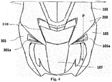
- Fig. 4 illustrates a front view of a front portion of the vehicle.
- the vehicle 100 comprises one or more front bottom panels.
- the one or more bottom front panels 105, 301 include the right front bottom panel 301 and the left bottom panel 105.
- the one or more bottom front panels 105, 301 include at least one louvre 105a and 301a respectively.
- the at least one louvre 105a and 301a are disposed at a close proximity to the headlamp assembly 110.
- the atmospheric air received by the at least one louvre 105a and 301a is circulated in the inner chamber comprising the rear portion of the headlamp assembly 110.
- the air circulation facilitates cooling of the heated LEDs of the headlamp assembly 110.
- the one or more bottom front panels 105, 301 are disposed rearwardly to and on either sides of the front wheel 101.
- the one or more bottom front panels 105, 301 protect the legs of the rider disposed on the floorboard assembly (not shown) during riding conditions.
- the one or more bottom front panels 105, 301 encounter the mud, dust, water particles, and any other foreign materials picked up by the front wheel 101 and splashed rearwardly during vehicle running condition. Thereby, preventing the same from reaching the rider.
- Fig. 5 illustrates a sectional view of the at least one louvre assembled with the one or more front bottom panels taken along pq axis as shown in the Fig. 4 .
- the at least one louvre 105a is detachably attached to the one or more front bottom panels 105.
- the at least one louvre 105a is snap fitted to one or more portions of the left bottom front panel 105.
- the snap fit leads to overlap 302 between the at least one louvre 105a and the one or more portions of the left bottom front panel 105 ensures effective fit and finish and prevents any see through gaps.
- the at least one louvre 105a includes at least one opening 105aa configured to receive atmospheric air.
- the at least one louvre 105a includes an extension member 105ab enabling detachable attachment of the at least one louvre 105a to the rear surface of the left bottom front panel 105.
- the rear surface of the left bottom front panel 105 includes one or more bosses 304 configured to receive the extension member 105ab.
- the at least one louvre 105a is also screwed to the one or more bosses 304 to ensure effective fitment and achieve efficient fit and finish.
- the top front panel 103 and at least a portion of the left bottom front panel 105 overlap over each other.
- the overlapped portion 303 prevents gaps there between and also prevents entry of dust, mud, water particles, and any other foreign particles from entering.
- the overlapped portion 303 also achieves better fit and finish and accounts to aesthetic appeal of the vehicle.
- Fig. 6a illustrates a front view of a left front bottom panel according to an embodiment of the present invention.
- the left front bottom panel is configured to receive the at least one louvre 105a.
- the at least one louvre 105a is received by at least one cutout 105b provided in at least a portion of the left bottom front panel 105 as shown in Fig 6b .
- the at least one louvre 105a is further detachably attached to the one or more boss 304 disposed on the rear surface 105d of the left bottom front panel 105 as shown in the Fig. 5c .
- the at least one louvre 105a is attached to a tapered portion 105c of the left bottom front panel 105.
- the at least one cutout 105b includes one or more projections 105ba enabling snap fit with the associated part, in particular, with the at least one louvre.
- Fig. 7a illustrates a front perspective view of the at least one louvre according to an embodiment of the present invention.
- the at least one louvre 105a is in the shape of an arrow head.
- the at least one louvre 105a is configured to being accommodated in the cutout of the tapered portion of the left front bottom panel (not shown).
- the at least one louvre 105a includes at least one opening 105aa capable of receiving the atmospheric air.
- the at least one opening 105aa at the inlet is substantially facing downward with an angular intake passage oriented at an angle ⁇ , in particular, about 45 degrees with respect to a horizontal plane.
- the at least one louvre 105a includes the extension member 105ab projecting outwardly from a rear-louvre surface 105ac as shown in Fig. 7b .
- the extension member 105ab includes at least one hole 305 enabling detachable attachment of the at least one louvre 105a.
- Fig. 8 illustrates a detailed view of a portion of the top front panel and the left front bottom panel.
- the top front panel 103 includes one or more locating lugs 402 configured to be accommodated by one or more locating slots 401 disposed on a peripheral surface 401ps of the left front bottom panel 301.
- the one or more locating lugs 402 are securely received by the one or more locating slots 401, which keeps the left front bottom panel 301 secured to the top front panel 103.
- the one or more locating lugs 402 and the one or more locating slots 401 provides better fit and finish between the body panels.
- Fig. 9 illustrates a detailed view of an assembly of a portion of the top front panel and the left front bottom panel.
- the one or more locating lugs 402 on the top front panel 103 are securely received by the one or more locating slots 401 in the left front bottom panel 301.
- the one or more locating lugs 401 are of a predetermined height, which can easily protrude inside the one or more locating slots 401 during assembly. This saves the time during assembly of the body panels and in addition, also provides stable assembly and better fit and finish between the top front panel 103 and the left front bottom panel 301.
Landscapes
- Engineering & Computer Science (AREA)
- Mechanical Engineering (AREA)
- Automatic Cycles, And Cycles In General (AREA)
Claims (9)
- Véhicule de type scooter avec repose-pied (100) comprenant:un ensemble de guidon (109);un ensemble de phare (110) disposé sous ledit ensemble de guidon (109);un ensemble de structure avant (200) comprenant un panneau avant supérieur (103) configuré pour supporter au moins une partie dudit ensemble de phare (110); et un ensemble moteur (201) disposé vers l'arrière par rapport à un ensemble de plancher (108) s'étendant vers l'arrière depuis ledit ensemble de structure avant (200), dans lequel ledit ensemble de structure avant (200) comprend un ou plusieurs panneaux inférieurs avant (105, 301) s'étendant verticalement vers le bas à partir d'une surface la plus basse (103Lw) du panneau avant supérieur (103) et vers l'arrière vers le bas depuis la surface la plus basse (103Lw) jusqu'à un bord le plus en avant (108Fw) de l'ensemble de plancher (108), etdans lequel lesdits un ou plusieurs panneaux inférieurs avant (105, 301) incluent une partie conique (105c) disposée au niveau d'une jonction de jointure entre au moins une partie du panneau avant supérieur (103) et au moins une partie desdits un ou plusieurs panneaux inférieurs avant (105, 301), caractérisé en ce quelesdits un ou plusieurs panneaux inférieurs avant (105, 301), ledit panneau avant supérieur (103) et un couvercle arrière (113) forment une chambre intérieure à l'intérieur de laquelle la partie arrière de l'ensemble de phare (110) est dissimulée, et la partie conique (105c) comprend au moins une découpe (105b) pour recevoir au moins une grille (105a, 301a) disposée à proximité immédiate dudit ensemble de phare (110) et capable de diriger l'air vers l'intérieur de la chambre intérieure pour refroidir l'ensemble projecteur (110).
- Véhicule de type scooter avec repose-pied (100) selon la revendication 1, dans lequel ladite au moins une grille (105a) comprend un élément d'extension (105ab) faisant saillie vers l'extérieur depuis une surface de grille arrière (105ac).
- Véhicule avec repose-pied (100) selon la revendication 1, dans lequel au moins une partie de ladite au moins une grille (105a, 301a) est configurée pour chevaucher (302) une ou plusieurs parties desdits un ou plusieurs panneaux avant inférieurs (105, 301).
- Véhicule de type scooter avec repose-pied (100) selon la revendication 1, dans lequel ledit panneau avant supérieur (103) comprend une ou plusieurs pattes de positionnement (402), lesdites une ou plusieurs pattes de positionnement (402) ayant une hauteur prédéterminée.
- Véhicule de type scooter avec repose-pied (100) selon la revendication 1, dans lequel lesdits un ou plusieurs panneaux avant inférieurs (105, 301) comprennent une ou plusieurs fentes de positionnement (401) disposées sur une surface périphérique (401ps) en une proximité étroite avec ledit panneau avant supérieur (103) dans un état assemblé.
- Véhicule de type scooter avec repose-pied (100) selon la revendication 1, dans lequel lesdits un ou plusieurs panneaux avant inférieurs (105, 301) sont fixés de manière fixe audit panneau avant supérieur (103) .
- Véhicule de type scooter avec repose-pied (100) selon la revendication 1, dans lequel ladite au moins une grille (105a, 301a) comprend au moins une ouverture (105aa), ladite au moins une ouverture (105aa) étant substantiellement tournée vers le bas à un angle α étant d'environ 45 degrés par rapport à un plan horizontal.
- Véhicule de type scooter avec repose-pied (100) selon la revendication 1 ou la revendication 2, dans lequel lesdits un ou plusieurs panneaux avant inférieurs (105 301) comprennent une surface arrière (105d) comprenant un ou plusieurs bossages (304) configurés pour recevoir une structure en forme d'étiquette (105ab) permettant une fixation détachable de ladite au moins une grille (105a) à la surface arrière (105d).
- Véhicule de type scooter avec repose-pied (100) selon la revendication 4 et la revendication 5, dans lequel lesdites une ou plusieurs pattes de positionnement (402) sont configurées pour être reçues par lesdites une ou plusieurs fentes de positionnement (401).
Applications Claiming Priority (1)
| Application Number | Priority Date | Filing Date | Title |
|---|---|---|---|
| IN201741011633 | 2017-03-31 |
Publications (2)
| Publication Number | Publication Date |
|---|---|
| EP3381776A1 EP3381776A1 (fr) | 2018-10-03 |
| EP3381776B1 true EP3381776B1 (fr) | 2020-11-11 |
Family
ID=61873312
Family Applications (1)
| Application Number | Title | Priority Date | Filing Date |
|---|---|---|---|
| EP18164971.6A Not-in-force EP3381776B1 (fr) | 2017-03-31 | 2018-03-29 | Véhicule de type scooter avec repose-pied |
Country Status (2)
| Country | Link |
|---|---|
| EP (1) | EP3381776B1 (fr) |
| CN (1) | CN108688755A (fr) |
Families Citing this family (2)
| Publication number | Priority date | Publication date | Assignee | Title |
|---|---|---|---|---|
| JP6927941B2 (ja) * | 2018-09-27 | 2021-09-01 | 本田技研工業株式会社 | 鞍乗型車両 |
| JP7212799B2 (ja) * | 2019-03-16 | 2023-01-25 | ティーヴィーエス モーター カンパニー リミテッド | 2輪車両用のフットレストアセンブリ |
Family Cites Families (4)
| Publication number | Priority date | Publication date | Assignee | Title |
|---|---|---|---|---|
| JPS6377885U (fr) * | 1986-11-11 | 1988-05-23 | ||
| JP4363875B2 (ja) * | 2003-03-25 | 2009-11-11 | 本田技研工業株式会社 | 自動二輪車における車体カバー構造 |
| JP5032142B2 (ja) * | 2007-02-13 | 2012-09-26 | ヤマハ発動機株式会社 | 自動二輪車 |
| US7607712B2 (en) * | 2007-02-28 | 2009-10-27 | Yamaha Hatsudoki Kabushiki Kaisha | Structure of side cover for motorcycle |
-
2018
- 2018-03-29 EP EP18164971.6A patent/EP3381776B1/fr not_active Not-in-force
- 2018-03-30 CN CN201810293411.2A patent/CN108688755A/zh active Pending
Non-Patent Citations (1)
| Title |
|---|
| None * |
Also Published As
| Publication number | Publication date |
|---|---|
| EP3381776A1 (fr) | 2018-10-03 |
| CN108688755A (zh) | 2018-10-23 |
Similar Documents
| Publication | Publication Date | Title |
|---|---|---|
| US7387180B2 (en) | Air guide structure in motor vehicle leg shield | |
| US9080737B2 (en) | Lighting device for vehicle, and mounting structure for the device | |
| JP5551979B2 (ja) | 乗物のランプ配置構造 | |
| US10391925B2 (en) | Vehicle headlight with a plurality of inner non spherical lenses transmitting light from a high beam and a low beam light source | |
| EP2075179B1 (fr) | Motocyclette | |
| US10935201B2 (en) | Lighting apparatus disposition structure for saddle riding vehicle | |
| EP2500638B1 (fr) | Dispositif de phare | |
| CN102700658A (zh) | 骑乘式车辆 | |
| US9371104B2 (en) | Headlight device for motorcycle | |
| US20120285762A1 (en) | Motorcycle | |
| US20180093729A1 (en) | Lighting device structure including auxiliary illumination | |
| EP3381776B1 (fr) | Véhicule de type scooter avec repose-pied | |
| JP2016005942A (ja) | 鞍乗型車両 | |
| US20220315154A1 (en) | Saddle-ride vehicle | |
| EP3560805B1 (fr) | Véhicule à enfourcher | |
| US7513559B2 (en) | Vehicle | |
| US20170015378A1 (en) | Direction indicator and rearview mirror structure of vehicle | |
| JP5947536B2 (ja) | 鞍乗型車両 | |
| JP6752741B2 (ja) | 鞍乗り型車両の灯火装置配置構造 | |
| JP5851230B2 (ja) | 鞍乗型車両 | |
| JP6814193B2 (ja) | 車両用灯火器 | |
| JP7732826B2 (ja) | 鞍乗型車両及び探知構造 | |
| JP7470723B2 (ja) | 鞍乗り型車両 | |
| EP4247697A1 (fr) | Véhicule | |
| CN117184285A (zh) | 鞍乘型车辆 |
Legal Events
| Date | Code | Title | Description |
|---|---|---|---|
| PUAI | Public reference made under article 153(3) epc to a published international application that has entered the european phase |
Free format text: ORIGINAL CODE: 0009012 |
|
| STAA | Information on the status of an ep patent application or granted ep patent |
Free format text: STATUS: THE APPLICATION HAS BEEN PUBLISHED |
|
| AK | Designated contracting states |
Kind code of ref document: A1 Designated state(s): AL AT BE BG CH CY CZ DE DK EE ES FI FR GB GR HR HU IE IS IT LI LT LU LV MC MK MT NL NO PL PT RO RS SE SI SK SM TR |
|
| AX | Request for extension of the european patent |
Extension state: BA ME |
|
| STAA | Information on the status of an ep patent application or granted ep patent |
Free format text: STATUS: REQUEST FOR EXAMINATION WAS MADE |
|
| 17P | Request for examination filed |
Effective date: 20190326 |
|
| RBV | Designated contracting states (corrected) |
Designated state(s): AL AT BE BG CH CY CZ DE DK EE ES FI FR GB GR HR HU IE IS IT LI LT LU LV MC MK MT NL NO PL PT RO RS SE SI SK SM TR |
|
| STAA | Information on the status of an ep patent application or granted ep patent |
Free format text: STATUS: EXAMINATION IS IN PROGRESS |
|
| 17Q | First examination report despatched |
Effective date: 20190909 |
|
| REG | Reference to a national code |
Ref country code: DE Ref legal event code: R079 Ref document number: 602018009535 Country of ref document: DE Free format text: PREVIOUS MAIN CLASS: B62J0017020000 Ipc: B62J0017100000 |
|
| RIC1 | Information provided on ipc code assigned before grant |
Ipc: B62K 11/10 20060101ALI20200605BHEP Ipc: B62J 17/06 20060101ALI20200605BHEP Ipc: B62J 17/10 20200101AFI20200605BHEP |
|
| GRAP | Despatch of communication of intention to grant a patent |
Free format text: ORIGINAL CODE: EPIDOSNIGR1 |
|
| STAA | Information on the status of an ep patent application or granted ep patent |
Free format text: STATUS: GRANT OF PATENT IS INTENDED |
|
| INTG | Intention to grant announced |
Effective date: 20200827 |
|
| GRAS | Grant fee paid |
Free format text: ORIGINAL CODE: EPIDOSNIGR3 |
|
| GRAA | (expected) grant |
Free format text: ORIGINAL CODE: 0009210 |
|
| STAA | Information on the status of an ep patent application or granted ep patent |
Free format text: STATUS: THE PATENT HAS BEEN GRANTED |
|
| AK | Designated contracting states |
Kind code of ref document: B1 Designated state(s): AL AT BE BG CH CY CZ DE DK EE ES FI FR GB GR HR HU IE IS IT LI LT LU LV MC MK MT NL NO PL PT RO RS SE SI SK SM TR |
|
| REG | Reference to a national code |
Ref country code: GB Ref legal event code: FG4D |
|
| REG | Reference to a national code |
Ref country code: CH Ref legal event code: EP |
|
| REG | Reference to a national code |
Ref country code: AT Ref legal event code: REF Ref document number: 1333208 Country of ref document: AT Kind code of ref document: T Effective date: 20201115 |
|
| REG | Reference to a national code |
Ref country code: DE Ref legal event code: R096 Ref document number: 602018009535 Country of ref document: DE |
|
| REG | Reference to a national code |
Ref country code: IE Ref legal event code: FG4D |
|
| REG | Reference to a national code |
Ref country code: NL Ref legal event code: MP Effective date: 20201111 |
|
| REG | Reference to a national code |
Ref country code: AT Ref legal event code: MK05 Ref document number: 1333208 Country of ref document: AT Kind code of ref document: T Effective date: 20201111 |
|
| PG25 | Lapsed in a contracting state [announced via postgrant information from national office to epo] |
Ref country code: RS Free format text: LAPSE BECAUSE OF FAILURE TO SUBMIT A TRANSLATION OF THE DESCRIPTION OR TO PAY THE FEE WITHIN THE PRESCRIBED TIME-LIMIT Effective date: 20201111 Ref country code: PT Free format text: LAPSE BECAUSE OF FAILURE TO SUBMIT A TRANSLATION OF THE DESCRIPTION OR TO PAY THE FEE WITHIN THE PRESCRIBED TIME-LIMIT Effective date: 20210311 Ref country code: FI Free format text: LAPSE BECAUSE OF FAILURE TO SUBMIT A TRANSLATION OF THE DESCRIPTION OR TO PAY THE FEE WITHIN THE PRESCRIBED TIME-LIMIT Effective date: 20201111 Ref country code: GR Free format text: LAPSE BECAUSE OF FAILURE TO SUBMIT A TRANSLATION OF THE DESCRIPTION OR TO PAY THE FEE WITHIN THE PRESCRIBED TIME-LIMIT Effective date: 20210212 Ref country code: NO Free format text: LAPSE BECAUSE OF FAILURE TO SUBMIT A TRANSLATION OF THE DESCRIPTION OR TO PAY THE FEE WITHIN THE PRESCRIBED TIME-LIMIT Effective date: 20210211 |
|
| PG25 | Lapsed in a contracting state [announced via postgrant information from national office to epo] |
Ref country code: AT Free format text: LAPSE BECAUSE OF FAILURE TO SUBMIT A TRANSLATION OF THE DESCRIPTION OR TO PAY THE FEE WITHIN THE PRESCRIBED TIME-LIMIT Effective date: 20201111 Ref country code: PL Free format text: LAPSE BECAUSE OF FAILURE TO SUBMIT A TRANSLATION OF THE DESCRIPTION OR TO PAY THE FEE WITHIN THE PRESCRIBED TIME-LIMIT Effective date: 20201111 Ref country code: LV Free format text: LAPSE BECAUSE OF FAILURE TO SUBMIT A TRANSLATION OF THE DESCRIPTION OR TO PAY THE FEE WITHIN THE PRESCRIBED TIME-LIMIT Effective date: 20201111 Ref country code: IS Free format text: LAPSE BECAUSE OF FAILURE TO SUBMIT A TRANSLATION OF THE DESCRIPTION OR TO PAY THE FEE WITHIN THE PRESCRIBED TIME-LIMIT Effective date: 20210311 Ref country code: SE Free format text: LAPSE BECAUSE OF FAILURE TO SUBMIT A TRANSLATION OF THE DESCRIPTION OR TO PAY THE FEE WITHIN THE PRESCRIBED TIME-LIMIT Effective date: 20201111 Ref country code: BG Free format text: LAPSE BECAUSE OF FAILURE TO SUBMIT A TRANSLATION OF THE DESCRIPTION OR TO PAY THE FEE WITHIN THE PRESCRIBED TIME-LIMIT Effective date: 20210211 |
|
| REG | Reference to a national code |
Ref country code: LT Ref legal event code: MG9D |
|
| PG25 | Lapsed in a contracting state [announced via postgrant information from national office to epo] |
Ref country code: HR Free format text: LAPSE BECAUSE OF FAILURE TO SUBMIT A TRANSLATION OF THE DESCRIPTION OR TO PAY THE FEE WITHIN THE PRESCRIBED TIME-LIMIT Effective date: 20201111 |
|
| PG25 | Lapsed in a contracting state [announced via postgrant information from national office to epo] |
Ref country code: LT Free format text: LAPSE BECAUSE OF FAILURE TO SUBMIT A TRANSLATION OF THE DESCRIPTION OR TO PAY THE FEE WITHIN THE PRESCRIBED TIME-LIMIT Effective date: 20201111 Ref country code: SK Free format text: LAPSE BECAUSE OF FAILURE TO SUBMIT A TRANSLATION OF THE DESCRIPTION OR TO PAY THE FEE WITHIN THE PRESCRIBED TIME-LIMIT Effective date: 20201111 Ref country code: RO Free format text: LAPSE BECAUSE OF FAILURE TO SUBMIT A TRANSLATION OF THE DESCRIPTION OR TO PAY THE FEE WITHIN THE PRESCRIBED TIME-LIMIT Effective date: 20201111 Ref country code: EE Free format text: LAPSE BECAUSE OF FAILURE TO SUBMIT A TRANSLATION OF THE DESCRIPTION OR TO PAY THE FEE WITHIN THE PRESCRIBED TIME-LIMIT Effective date: 20201111 Ref country code: CZ Free format text: LAPSE BECAUSE OF FAILURE TO SUBMIT A TRANSLATION OF THE DESCRIPTION OR TO PAY THE FEE WITHIN THE PRESCRIBED TIME-LIMIT Effective date: 20201111 Ref country code: SM Free format text: LAPSE BECAUSE OF FAILURE TO SUBMIT A TRANSLATION OF THE DESCRIPTION OR TO PAY THE FEE WITHIN THE PRESCRIBED TIME-LIMIT Effective date: 20201111 |
|
| REG | Reference to a national code |
Ref country code: DE Ref legal event code: R097 Ref document number: 602018009535 Country of ref document: DE |
|
| PG25 | Lapsed in a contracting state [announced via postgrant information from national office to epo] |
Ref country code: DK Free format text: LAPSE BECAUSE OF FAILURE TO SUBMIT A TRANSLATION OF THE DESCRIPTION OR TO PAY THE FEE WITHIN THE PRESCRIBED TIME-LIMIT Effective date: 20201111 |
|
| PLBE | No opposition filed within time limit |
Free format text: ORIGINAL CODE: 0009261 |
|
| STAA | Information on the status of an ep patent application or granted ep patent |
Free format text: STATUS: NO OPPOSITION FILED WITHIN TIME LIMIT |
|
| 26N | No opposition filed |
Effective date: 20210812 |
|
| PG25 | Lapsed in a contracting state [announced via postgrant information from national office to epo] |
Ref country code: MC Free format text: LAPSE BECAUSE OF FAILURE TO SUBMIT A TRANSLATION OF THE DESCRIPTION OR TO PAY THE FEE WITHIN THE PRESCRIBED TIME-LIMIT Effective date: 20201111 Ref country code: NL Free format text: LAPSE BECAUSE OF FAILURE TO SUBMIT A TRANSLATION OF THE DESCRIPTION OR TO PAY THE FEE WITHIN THE PRESCRIBED TIME-LIMIT Effective date: 20201111 Ref country code: AL Free format text: LAPSE BECAUSE OF FAILURE TO SUBMIT A TRANSLATION OF THE DESCRIPTION OR TO PAY THE FEE WITHIN THE PRESCRIBED TIME-LIMIT Effective date: 20201111 |
|
| REG | Reference to a national code |
Ref country code: CH Ref legal event code: PL |
|
| PG25 | Lapsed in a contracting state [announced via postgrant information from national office to epo] |
Ref country code: SI Free format text: LAPSE BECAUSE OF FAILURE TO SUBMIT A TRANSLATION OF THE DESCRIPTION OR TO PAY THE FEE WITHIN THE PRESCRIBED TIME-LIMIT Effective date: 20201111 |
|
| REG | Reference to a national code |
Ref country code: BE Ref legal event code: MM Effective date: 20210331 |
|
| PG25 | Lapsed in a contracting state [announced via postgrant information from national office to epo] |
Ref country code: CH Free format text: LAPSE BECAUSE OF NON-PAYMENT OF DUE FEES Effective date: 20210331 Ref country code: IE Free format text: LAPSE BECAUSE OF NON-PAYMENT OF DUE FEES Effective date: 20210329 Ref country code: LU Free format text: LAPSE BECAUSE OF NON-PAYMENT OF DUE FEES Effective date: 20210329 Ref country code: LI Free format text: LAPSE BECAUSE OF NON-PAYMENT OF DUE FEES Effective date: 20210331 Ref country code: ES Free format text: LAPSE BECAUSE OF FAILURE TO SUBMIT A TRANSLATION OF THE DESCRIPTION OR TO PAY THE FEE WITHIN THE PRESCRIBED TIME-LIMIT Effective date: 20201111 |
|
| PGFP | Annual fee paid to national office [announced via postgrant information from national office to epo] |
Ref country code: DE Payment date: 20220322 Year of fee payment: 5 |
|
| PG25 | Lapsed in a contracting state [announced via postgrant information from national office to epo] |
Ref country code: IS Free format text: LAPSE BECAUSE OF FAILURE TO SUBMIT A TRANSLATION OF THE DESCRIPTION OR TO PAY THE FEE WITHIN THE PRESCRIBED TIME-LIMIT Effective date: 20210311 |
|
| PGFP | Annual fee paid to national office [announced via postgrant information from national office to epo] |
Ref country code: IT Payment date: 20220322 Year of fee payment: 5 |
|
| PG25 | Lapsed in a contracting state [announced via postgrant information from national office to epo] |
Ref country code: BE Free format text: LAPSE BECAUSE OF NON-PAYMENT OF DUE FEES Effective date: 20210331 |
|
| GBPC | Gb: european patent ceased through non-payment of renewal fee |
Effective date: 20220329 |
|
| PG25 | Lapsed in a contracting state [announced via postgrant information from national office to epo] |
Ref country code: GB Free format text: LAPSE BECAUSE OF NON-PAYMENT OF DUE FEES Effective date: 20220329 |
|
| PGFP | Annual fee paid to national office [announced via postgrant information from national office to epo] |
Ref country code: FR Payment date: 20230330 Year of fee payment: 6 |
|
| PG25 | Lapsed in a contracting state [announced via postgrant information from national office to epo] |
Ref country code: CY Free format text: LAPSE BECAUSE OF FAILURE TO SUBMIT A TRANSLATION OF THE DESCRIPTION OR TO PAY THE FEE WITHIN THE PRESCRIBED TIME-LIMIT Effective date: 20201111 |
|
| PG25 | Lapsed in a contracting state [announced via postgrant information from national office to epo] |
Ref country code: HU Free format text: LAPSE BECAUSE OF FAILURE TO SUBMIT A TRANSLATION OF THE DESCRIPTION OR TO PAY THE FEE WITHIN THE PRESCRIBED TIME-LIMIT; INVALID AB INITIO Effective date: 20180329 |
|
| REG | Reference to a national code |
Ref country code: DE Ref legal event code: R119 Ref document number: 602018009535 Country of ref document: DE |
|
| PG25 | Lapsed in a contracting state [announced via postgrant information from national office to epo] |
Ref country code: DE Free format text: LAPSE BECAUSE OF NON-PAYMENT OF DUE FEES Effective date: 20231003 |
|
| PG25 | Lapsed in a contracting state [announced via postgrant information from national office to epo] |
Ref country code: MK Free format text: LAPSE BECAUSE OF FAILURE TO SUBMIT A TRANSLATION OF THE DESCRIPTION OR TO PAY THE FEE WITHIN THE PRESCRIBED TIME-LIMIT Effective date: 20201111 Ref country code: IT Free format text: LAPSE BECAUSE OF NON-PAYMENT OF DUE FEES Effective date: 20230329 |
|
| PG25 | Lapsed in a contracting state [announced via postgrant information from national office to epo] |
Ref country code: TR Free format text: LAPSE BECAUSE OF FAILURE TO SUBMIT A TRANSLATION OF THE DESCRIPTION OR TO PAY THE FEE WITHIN THE PRESCRIBED TIME-LIMIT Effective date: 20201111 |
|
| PG25 | Lapsed in a contracting state [announced via postgrant information from national office to epo] |
Ref country code: MT Free format text: LAPSE BECAUSE OF FAILURE TO SUBMIT A TRANSLATION OF THE DESCRIPTION OR TO PAY THE FEE WITHIN THE PRESCRIBED TIME-LIMIT Effective date: 20201111 |
|
| PG25 | Lapsed in a contracting state [announced via postgrant information from national office to epo] |
Ref country code: FR Free format text: LAPSE BECAUSE OF NON-PAYMENT OF DUE FEES Effective date: 20240331 |
|
| PG25 | Lapsed in a contracting state [announced via postgrant information from national office to epo] |
Ref country code: FR Free format text: LAPSE BECAUSE OF NON-PAYMENT OF DUE FEES Effective date: 20240331 |