EP3381785A1 - Dispositif d'entraînement et moyen de transport - Google Patents
Dispositif d'entraînement et moyen de transport Download PDFInfo
- Publication number
- EP3381785A1 EP3381785A1 EP17163704.4A EP17163704A EP3381785A1 EP 3381785 A1 EP3381785 A1 EP 3381785A1 EP 17163704 A EP17163704 A EP 17163704A EP 3381785 A1 EP3381785 A1 EP 3381785A1
- Authority
- EP
- European Patent Office
- Prior art keywords
- drive
- shaft
- lever
- drive device
- primary
- Prior art date
- Legal status (The legal status is an assumption and is not a legal conclusion. Google has not performed a legal analysis and makes no representation as to the accuracy of the status listed.)
- Withdrawn
Links
- 230000005540 biological transmission Effects 0.000 claims description 115
- 230000008878 coupling Effects 0.000 claims description 77
- 238000010168 coupling process Methods 0.000 claims description 77
- 238000005859 coupling reaction Methods 0.000 claims description 77
- 230000006978 adaptation Effects 0.000 claims description 14
- 230000033001 locomotion Effects 0.000 description 40
- 210000003205 muscle Anatomy 0.000 description 7
- 239000000463 material Substances 0.000 description 5
- 230000001360 synchronised effect Effects 0.000 description 4
- 238000012423 maintenance Methods 0.000 description 3
- 229910000831 Steel Inorganic materials 0.000 description 2
- 208000027418 Wounds and injury Diseases 0.000 description 2
- 230000002411 adverse Effects 0.000 description 2
- 230000006378 damage Effects 0.000 description 2
- 206010016256 fatigue Diseases 0.000 description 2
- 208000014674 injury Diseases 0.000 description 2
- 210000002414 leg Anatomy 0.000 description 2
- 238000004519 manufacturing process Methods 0.000 description 2
- 238000005096 rolling process Methods 0.000 description 2
- 239000010959 steel Substances 0.000 description 2
- 229920000049 Carbon (fiber) Polymers 0.000 description 1
- 229920002430 Fibre-reinforced plastic Polymers 0.000 description 1
- 230000001174 ascending effect Effects 0.000 description 1
- 210000001217 buttock Anatomy 0.000 description 1
- 239000004917 carbon fiber Substances 0.000 description 1
- 230000003111 delayed effect Effects 0.000 description 1
- 238000006073 displacement reaction Methods 0.000 description 1
- 238000005516 engineering process Methods 0.000 description 1
- 210000003414 extremity Anatomy 0.000 description 1
- 239000011151 fibre-reinforced plastic Substances 0.000 description 1
- 230000005484 gravity Effects 0.000 description 1
- 239000002184 metal Substances 0.000 description 1
- VNWKTOKETHGBQD-UHFFFAOYSA-N methane Chemical compound C VNWKTOKETHGBQD-UHFFFAOYSA-N 0.000 description 1
- 230000003387 muscular Effects 0.000 description 1
- 230000010363 phase shift Effects 0.000 description 1
- 239000004033 plastic Substances 0.000 description 1
- 229920003023 plastic Polymers 0.000 description 1
- 230000035939 shock Effects 0.000 description 1
- 208000024891 symptom Diseases 0.000 description 1
Images





Classifications
-
- B—PERFORMING OPERATIONS; TRANSPORTING
- B62—LAND VEHICLES FOR TRAVELLING OTHERWISE THAN ON RAILS
- B62M—RIDER PROPULSION OF WHEELED VEHICLES OR SLEDGES; POWERED PROPULSION OF SLEDGES OR SINGLE-TRACK CYCLES; TRANSMISSIONS SPECIALLY ADAPTED FOR SUCH VEHICLES
- B62M1/00—Rider propulsion of wheeled vehicles
- B62M1/24—Rider propulsion of wheeled vehicles with reciprocating levers, e.g. foot levers
-
- B—PERFORMING OPERATIONS; TRANSPORTING
- B62—LAND VEHICLES FOR TRAVELLING OTHERWISE THAN ON RAILS
- B62M—RIDER PROPULSION OF WHEELED VEHICLES OR SLEDGES; POWERED PROPULSION OF SLEDGES OR SINGLE-TRACK CYCLES; TRANSMISSIONS SPECIALLY ADAPTED FOR SUCH VEHICLES
- B62M1/00—Rider propulsion of wheeled vehicles
- B62M1/24—Rider propulsion of wheeled vehicles with reciprocating levers, e.g. foot levers
- B62M1/26—Rider propulsion of wheeled vehicles with reciprocating levers, e.g. foot levers characterised by rotary cranks combined with reciprocating levers
-
- B—PERFORMING OPERATIONS; TRANSPORTING
- B62—LAND VEHICLES FOR TRAVELLING OTHERWISE THAN ON RAILS
- B62M—RIDER PROPULSION OF WHEELED VEHICLES OR SLEDGES; POWERED PROPULSION OF SLEDGES OR SINGLE-TRACK CYCLES; TRANSMISSIONS SPECIALLY ADAPTED FOR SUCH VEHICLES
- B62M1/00—Rider propulsion of wheeled vehicles
- B62M1/24—Rider propulsion of wheeled vehicles with reciprocating levers, e.g. foot levers
- B62M1/30—Rider propulsion of wheeled vehicles with reciprocating levers, e.g. foot levers characterised by the use of intermediate gears
-
- B—PERFORMING OPERATIONS; TRANSPORTING
- B62—LAND VEHICLES FOR TRAVELLING OTHERWISE THAN ON RAILS
- B62M—RIDER PROPULSION OF WHEELED VEHICLES OR SLEDGES; POWERED PROPULSION OF SLEDGES OR SINGLE-TRACK CYCLES; TRANSMISSIONS SPECIALLY ADAPTED FOR SUCH VEHICLES
- B62M15/00—Transmissions characterised by use of crank shafts and coupling rods
Definitions
- the invention relates to a drive device and a means of transport, in particular a recumbent, with such a drive device.
- Recumbents which the user uses almost lying, with a pedal drive are for example from the DE102005058245A1 known.
- a disadvantage of a pedal drive in recumbents is the high space requirement for the crank movement, in which the foot pedals are guided in a circular motion about a drive shaft. As a result, the drive device must be located further away from the ground, whereby the center of gravity comes to rest, which adversely affects the stability.
- the legs of the user for the crank movement must be strongly deflected from the lying position up and down, which also affects the stability adversely.
- the lying crank movement leads to a high muscular load of the user.
- a bicycle with a drive device which has drive levers, which in the rest position can be oriented at least approximately horizontally and are deflected upwards and downwards when the bicycle is operated.
- One end of the drive lever is coupled to the rear axle during a portion of the lever movement and decoupled therefrom during the remainder of the lever movement.
- the ongoing coupling and decoupling is prone to failure and requires high wear.
- the power transmission to the axle also takes place essentially via sliding friction, which is inefficient. It should be noted that the seated user can not optimally transfer the muscle power to the pedals, which is why rapid fatigue is to be expected.
- the present invention is therefore based on the object to provide an improved drive device, which advantageously in a means of transport, such as a recumbent can be used. Furthermore, a means of transport is to provide with such a drive device.
- the drive device should be ergonomically advantageous operable by a user manually or by foot.
- the drive device should be actuated by means of a uniform and muscle-gentle movement.
- the muscle power should be able to be efficiently transferred to the drive device.
- the drive device should be simple and stable and hardly require maintenance.
- a transmission device is to be created, by means of the driving forces and drive moments space-saving over long distances practically without losses are transferable.
- the drive means should take up little space, so that between the drive device and driven elements only a small cross section for the transmission of driving forces is required.
- the transmission device By means of the transmission device, very high drive torques should be practically transferable without loss, so that the transmission device can also be used universally in machines, which are not operated with muscle power, independently of the drive device according to the invention.
- the power transmission should be done safely and safely via a transmission channel, which has a minimum cross-section. Even when touching the drive means during operation injuries should be largely avoided.
- the transmission device should not require any maintenance even after a long period of operation.
- the transmission device should be coupled in a simple manner with any drive devices and particularly advantageous with the inventive drive device.
- the drive device and / or the transmission device should be particularly advantageous in the inventive transport used, which can be operated comfortably and efficiently by a user.
- the drive device and / or the transmission device should be advantageously used in particular in a recumbent bike and take up little space, so that the user has a high freedom of movement and is available for the further structural design of the recumbent much space. From the lying position, the user should be able to optimally transfer his physical strength to the drive device without getting tired.
- the in a means of transport, such as a recumbent with two or three wheels, advantageously usable drive device comprises a first and a second drive lever having first Hebelend nowadayse, where preferably each an actuating element, such as a foot pedal is provided, the second Hebelend thoroughlye having coupled to each other, which are rotatably supported in preferably mutually parallel and spaced-apart planes, and which are coupled to a drive shaft which is rotatably mounted in a bearing device.
- each drive lever is rotatably connected via an arranged between the first and the second lever end primary shaft with an associated primary lever which is rotatably connected to the drive shaft.
- the second Hebelend are each directly or via a secondary shaft and connected via a secondary lever with an auxiliary shaft which is held by the bearing device.
- the primary waves and the secondary waves of each drive lever are held by adapter devices against each other.
- the first and second drive levers which are oriented upwards, are moved back and forth manually or through the feet of the user.
- the drive levers are deflected symmetrically to a central axis, which is aligned perpendicular to the longitudinal axis of the transport and typically parallel to the vertical.
- the drive levers are rotated with a mutual phase shift of 180 ° with a rotation angle back and forth, which is preferably in a range between 60 ° and 120 °. Particularly preferred angles of rotation are in the range between 80 ° and 100 °.
- the first drive lever is rotated forward or backward, the second drive lever is rotated back or forth by the same amount.
- the drive lever are alternately raised and lowered during the forward and backward movement.
- the primary lever with the drive shaft are each rotated by 360 °, whereby the transport means is driven by a transmission device.
- the shorter primary levers are rotated about the drive shaft. Due to the resulting alternating vertical movements of the drive lever with a movement of the primary shafts and secondary shafts relative to one another according to the invention a freewheeling of the primary shafts or secondary shafts provided so that they can move as needed relative to each other, preferably axially the drive levers.
- the adaptation devices have a provided in or on the associated drive lever and preferably aligned parallel thereto guide channel, within which the associated primary shaft or the associated secondary shaft is mounted displaceably and rotatably.
- the primary lever or the secondary lever can therefore be rotated against each other, while the mutually shifting primary waves and secondary waves receive the required freewheel by the primary shafts or secondary waves in the associated guide channel preferably along the longitudinal axis of the associated drive lever can move as needed.
- the adapter devices on the drive levers are each arranged on the end piece, which lies opposite the end piece with the actuating elements or the foot pedals.
- the adaptation device is therefore moved into the area in which lower forces and thus lower friction losses occur.
- high-quality pivot bearings are used for the primary waves and secondary waves, working lossless.
- high-quality slide bearings are preferably used for the primary shafts or secondary shafts which are displaced within an associated adaptation device.
- the adaptation devices may comprise articulated drive levers having a first and a second lever portion between the primary shafts and the secondary shafts which are interconnected by a lever joint.
- the primary lever or the secondary lever can therefore be rotated against each other, while the mutually shifting primary shafts and secondary shafts receive the required freewheel by tracking a mutual rotation of the two lever portions of the drive lever.
- friction losses are virtually completely avoided.
- the primary waves and secondary waves represent articulated joints, which can also be realized by other means.
- the guided in the guide channel primary shaft or secondary shaft can also be designed as a guide pin and optionally anchored in the guide channel.
- By engaging in the guide channel guide pin of the drive lever is precisely guided. Due to the precise guidance and the associated uniform movement, the drive axle is driven uniformly and optimally via the first coupling wheel.
- To avoid sliding friction of the guide pin or the secondary shaft in the region of the engagement in the guide channel is preferably provided with plain bearing elements or roller bearings.
- holding elements are provided which hold the guide pin or the primary shaft or secondary shaft within the guide channel displaceable
- the inventive drive device with the drive levers, the primary levers and, if present, the secondary levers, which are hinged together and to the drive shaft and the auxiliary shaft, is basically a lever drive.
- the drive lever, primary lever and secondary lever may be in the form of one-piece or multi-part longitudinal profiles, rods, bars with rounded or rectangular profile, in particular threaded rods, which are preferably adjustable in length.
- telescopically adjustable primary lever and / or secondary lever are provided.
- the drive shaft and the auxiliary shaft are coupled together so that they perform synchronous movements.
- This coupling can be done by drive chains or gears.
- the primary lever and / or the secondary lever can be advantageously integrated into these coupling wheels.
- the proportion of material between an eccentric connecting point of the primary waves or secondary waves and the axis of the disc or the wheel or the local drive shaft or auxiliary shaft thereby forms the primary lever or the secondary lever.
- the drive device can be advantageously synchronized and stabilized by means of the coupled coupling wheels.
- the drive shaft rotatably holds at least one first coupling wheel, which is optionally eccentrically connected to the associated primary shaft, so that the associated primary lever is an integral part of the first coupling wheel
- the auxiliary shaft preferably rotatably holds a second coupling wheel, which optionally eccentrically connected to the associated secondary shaft, so that the associated secondary lever is an integral part of the second coupling wheel.
- the first and the second coupling wheel and thus the drive shaft and the auxiliary shaft can be advantageously coupled together.
- the coupling wheels are preferably designed as gears which engage with each other. The operated with the first or second drive lever primary and secondary levers can therefore be advantageously integrated into the two coupling wheels.
- each drive lever is associated with a pair of coupling wheels into which the primary elevation and secondary levers are preferably integrated.
- the distance of the primary waves from the drive shaft and / or the distance of the secondary waves from the auxiliary shaft is preferably determined by appropriate positioning of the primary waves or secondary waves on the first or second coupling wheel or by adjusting the length of the primary lever or the secondary lever.
- the primary waves and / or the secondary waves can be optionally anchored on the associated coupling wheel in a plurality of defined positions.
- the coupling wheels and / or the primary lever or secondary lever preferably have a plurality of receiving openings, such as holes, in which the imported primary shafts and / or secondary shafts can be anchored.
- the receiving openings are for example radially offset from each other.
- a user-operable switching mechanism is provided, by means of which the lever lengths are preferably automatically adjustable.
- primary lever or secondary lever in the embodiment of intermeshing threaded elements, such as threaded sleeves and threaded rods are particularly advantageous.
- a corresponding threaded member such as the threaded rod can be rotated by a drive motor, whereby the Translation is infinitely changeable.
- the power supply of these drive motors can be done for example by means of batteries.
- the drive shaft of the drive device according to the invention can be coupled with any transmission means such as drive chains or cardan shafts.
- the drive device according to the invention can be coupled with a transmission device according to the invention.
- the drive shaft of the drive device and a first transmission shaft of the transmission device can be identical; that is, the drive device and the transmission device have a common shaft, which will be referred to below as the drive shaft when viewing the drive device and as the first transmission shaft when viewing the transmission device.
- this first transmission shaft is connected to a second transmission shaft by tension elements, which are preferably designed as cables or tension rods. At the opposite ends of the tension elements coupling elements are provided which can be coupled to the transmission waves.
- the first and second transmission shafts are preferably designed as crankshafts which have a plurality of cranks, which are each connected to one of the coupling elements of the tension elements.
- On the first transmission shaft along its longitudinal axis are thus laterally offset first cranks arranged, which are each connected by one of the tension elements with one of a plurality of second cranks, which are arranged laterally offset on the second transmission shaft along its longitudinal axis.
- the first and second cranks constituting segments of the first and second transmission shafts each have two crank plates connected to adjacent parts of the first and second transmission shafts, respectively which are interconnected by a bearing shaft, which serves to hold each of a coupling element of the tension elements.
- the coupling elements preferably comprise bearing sleeves or roller bearings, which are held by the bearing shafts of the cranks and which cause hardly any frictional losses during rotations relative to the bearing shafts.
- the tension elements are in contrast to drive chains virtually any load and maintenance.
- the tension elements can run in a very narrow transmission channel, which can be advantageously integrated into the frame structure of a vehicle, in particular a bicycle.
- the flexible but not extensible tension elements can be advantageously introduced via deflection wheels in the transmission channel and out of the transmission channel out.
- the cross section of the transmission channel can therefore be reduced to a few square centimeters, practically the cross section of the tension elements, so that maximum drive torques can be transmitted over a minimum cross section.
- first and second cranks are provided on the first and second transmission shaft, which are preferably configured and aligned identically, which are arranged incrementally rotated by 120 ° about the first and second transmission shaft and aligned such that the first corresponding to each other and second cranks are at least approximately aligned parallel to each other.
- the first and second transmission waves are synchronized.
- at least one of the tension elements is always loaded, so that the first and the second transmission shaft are firmly coupled and a uniform force transmission takes place.
- the elements of the drive device and the transmission device can be made of different materials, in particular metal and plastic.
- the first drive lever and / or the second drive lever and / or the first coupling wheel and / or the second coupling wheel made of steel and / or a fiber-reinforced plastic and / or made of a carbon fiber reinforced material. This achieves optimum stability and longevity with a reduced total weight.
- the individual device parts can therefore be made optionally of different materials.
- the drive device according to the invention and the transmission device according to the invention can be advantageously used in combination with one another, but also independently of one another.
- the drive device and / or the transmission device can be installed in combination or independently in any machine.
- the transmission device according to the invention which allows large forces and torques to be transmitted safely and safely over long distances from a first to a second transmission shaft and / or from the second to the first transmission shaft, can advantageously be used, for example, in production plants, production plants, or robotic plants ,
- the transmission device can be used for the drive or output.
- a contacting of the tension elements, for example, with one hand hardly causes injury, since the tension elements are moved axially and, in contrast to drive chains, have a smooth surface.
- the transmission device can be made arbitrarily or arbitrarily small, so that advantageous applications in all technical fields, in particular in Robotics but also in medical technology are possible, for example, to replace injured, degenerate or malformed limbs or support.
- a two- or three-wheeled recumbent with a reclining seat which is mounted on a frame structure, be equipped with a drive device according to the invention and / or with a transmission device according to the invention.
- the transport means comprises an electric motor, as a backup drive and / or as an additional drive, which is advantageously integrated into the frame structure and coupled to the drive shaft of the drive device or a transmission shaft of the transmission device.
- the drive device 2 according to the invention can be optimized by making all articulated connections with low-friction bearing elements, such as rolling bearings, e.g. Ball bearings, be provided.
- low-friction bearing elements such as rolling bearings, e.g. Ball bearings
- the primary shafts 221, 222 and secondary shafts 321, 322 are held in the driving levers 211, 212 by means of rolling bearings.
- Fig. 1a shows a transport means 1 according to the invention with three wheels 121, 122, 123, which are fastened to a frame structure 11.
- a reclining seat 13 is further attached, on which the user in a at least approximately lying position the transport means 1 can operate comfortably.
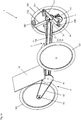
- the driving device 2 fastened to a bearing device 111 of the frame structure 11 comprises two upwardly directed and vertically inclined drive levers 211, 212 with operating elements 291, 292 and foot pedals which can be actuated by the user and displaced along a schematically shown movement curve 9, around one To drive drive shaft 34.
- the drive shaft 34 of the drive device 2 is coupled via an inventive transmission device 3 and further power transmission means 4 with the rear wheel 123 of the transport means 1.
- the further power transmission means 4 comprise a first power transmission ratio 41 coupled to the transmission device 3, which via a belt or a chain 42 drives a second power transmission level 43 which is connected to and coaxially aligned with the rear wheel 123 (see FIG Fig. 1b ).
- the transmission device 3 comprises tension elements 31, 32, 33, which are connected to the drive shaft 34 and by a transmission channel 110 integrated in the frame structure 11 to the rear to a second transmission shaft 35 (see Fig. 2a ) are guided, of which the power transmission ratio 41 is driven.
- Fig. 1b shows the transport 1 of Fig. 1a Within the cutaway transmission channel 110, the tension elements 31, 32, 33 are guided to the drive shaft 34, which is designed as a crankshaft and forms a common part of the drive device 2 and the transmission device 3 , If the drive device 2 and the Transmission device 3 are realized independently, so each of these devices 2, 3 is provided with such a shaft, ie, the drive device has a drive shaft and the transmission device has a first transmission shaft, which is driven directly or indirectly by a drive device.
- the drive shaft 34 can be configured as desired and adapted to any transmission devices.
- the drive shaft 34 may be cylindrical and connected at one end to the power transmission gear 41. In this case, however, the drive chain 42 would have to be led backwards, which is associated with the disadvantages described above.
- Fig. 2a shows the from the means of transport of Fig. 1 Removed drive device 2 and the coupled therewith transfer device 3, which is the rear side coupled to the other power transmission means 4.
- the drive device 2 will be described below with reference to FIG Fig. 3a explained in more detail.
- Fig. 2b shows the drive device 2 of Fig. 2a , extended with two coupled coupling wheels 261, 262 and the schematically shown movement curve 9, along which the actuators 291, 292 are guided during operation of the drive device 2.
- Fig. 3a shows the inventive drive device 2 of Fig. 2a isolated and in an enlarged view.
- Each drive lever 211; 212 is a primary shaft 241 disposed between a first and a second lever end 201, 202; 242 rotatable with an associated primary lever 221; 222 connected, which is non-rotatably connected to the drive shaft 34.
- the second end pieces of the drive lever 211; 212 are each connected via a secondary shaft 251, 252 and a secondary lever 231, 232 preferably non-rotatably connected to an auxiliary shaft 28 which is held in the bearing device 111.
- the primary waves 241; 242 and the secondary waves 251; 252 of each drive lever 211; 212 are held by adapter devices 2111, 2121 against each other.
- the adaptation devices 2111, 2121 which are provided in this embodiment of the drive device 2 at the second end pieces 202 of the drive lever 211, 212, each comprise a guide channel 2110, 2120, in which the associated secondary shaft 251, 252 is slidably and rotatably mounted.
- the primary levers 221, 222 are rotated about the longitudinal axis of the drive shaft 34, which is why the drive lever 211, 212 perform a vertical movement in addition to the horizontal movement.
- the guide channel 2110, 2120 is provided, which allows the second secondary shafts 251, 252 to be displaced relative to the associated drive lever 211, 212.
- the drive shaft 34 is configured as a crankshaft and has in this preferred embodiment, three cranks, which are each connected to one of the tension elements 31, 32, 33 of the inventive transmission device 3, which will be described below with reference to the FIGS. 5a and 5b will be described in more detail.
- the drive shaft 34 and the auxiliary shaft 28 are aligned parallel to each other by a bearing device 111, for example of two parallel to each other Bearing plates of the frame structure 11 (see Fig. 1b ), held rotatably at a fixed distance from each other.
- the drive shaft 34 and the auxiliary shaft 28 are coupled together by coupling means, such as gears or chains, such that they always rotate synchronously.
- Fig. 3b shows the inventive drive device 2 of Fig. 2b with the movement curve 9 as well as a first coupling wheel 261 arranged on the drive shaft 34 and a second coupling wheel 262 arranged on the auxiliary shaft 28, which are formed as toothed wheels and coupled to one another via the toothing.
- the drive shaft 34 and the auxiliary shaft 28 are thus coupled together and have, like the primary lever 221, 222 and the secondary lever 231, 232 opposite directions of rotation. Consequently, the primary waves 241, 242 and the secondary waves 251, 252 are cyclically opposed to each other and apart. The relative movement of the secondary shafts 251, 252 is thereby permitted by the associated adaptation device 2110, 2120.
- the drive shaft 34 and the auxiliary shaft 28 are preferably arranged coaxially with the drive axes of the coupling wheels 261, 262 and fixedly connected thereto.
- the primary lever 222 and the secondary lever 232 which are moved by the second drive lever 212, are directly adjacent to the coupling wheels 261, 262 and thus can be advantageously integrated into them. That is, the corresponding primary shaft 242 and secondary shaft 252 can, as in Fig. 6a shown to be an integral part of the coupling wheels 261, 262, if their radius is large enough.
- Coupling wheels 261, 262 may also be provided on the other end of the drive shaft 34 and the auxiliary shaft 28 and coupled in an analogous manner to the first drive lever 211.
- the primary lever 221, 222 and secondary lever 231, 232 can thus be integrated on both sides of the drive device 2 in the associated coupling wheels 261, 262.
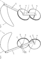
- FIGS. 4a to 4f illustrate the sequence of movement of the drive device 2 of Fig. 6a while the pedal 291 connected to the first drive lever 211 passes through half of the movement cam 9.
- the two coupling wheels 261, 262 perform in this movement a rotation by 180 ° in opposite directions of rotation, which is why the distance between the directly connected to the first coupling wheel 261 primary shaft 241 and directly connected to the second coupling wheel 262 secondary shaft 251 changes.
- This change in distance is compensated by the adapter device 2111 by the secondary shaft 251 within the guide channel 2110 of the adapter device 2111 moves down and back up.
- Fig. 4a shows the first drive lever 211 vertically aligned with the operating element 291 at the top in the middle of the movement curve 9.
- the operating element 291 is guided along the movement curve 9 to the left and down.
- the control element 291 is returned to the right at the bottom of the movement curve 9 in the middle. The further course along the second half of the movement curve 9 takes place in mirror image.
- Fig. 5a shows the inventive transmission device 3 of Fig. 1b in a preferred embodiment with three tension elements 31, 32, 33, by means of which a first transmission shaft 34, identical to the drive shaft 34 of Drive device 2 is, and a second transmission shaft 35, which is identical to the first transmission shaft 34 configured and identically aligned, are coupled together.
- the tension elements 31, 32, 33 which are provided on both sides with coupling elements 311, 312, 321; 322; 331, 332 are shown interrupted and can basically have any length.
- the first and the second transmission shaft 34, 35 are designed as crankshafts with three cranks each 341, 342, 343 and 351, 352, 353, each one of the coupling elements 311, 312; 321, 322; 331, 332 hold like in Fig. 5b for the coupling element 331 shown with a bearing opening 3310 are provided.
- Fig. 5b shows the first transmission wave 34 of Fig. 5a with the three laterally offset from each other and rotated by 120 ° from each other cranks 341, 342, 343, each having two crank plates 302 which are interconnected by a bearing shaft 301.
- the bearing shafts 301 are defined by the bearing openings 3310 in the coupling elements 311, 312, 321, 322; 331, 332 passed through and can rotate relative to these or with these.
- the coupling elements 311, 312; 321, 322; 331, 332 be provided with bearing elements, such as plain bearings or bearings.
- the drive shaft or first transmission shaft 34 is coupled to the second transmission shaft 35 such that they rotate synchronously with each other.
- the crank pairs 341, 351; 342, 352; 343, 353 also rotate synchronously and stay parallel to each other.
- the inventive transmission device 3 can therefore space-saving practically universally used for the transmission of high forces and high drive torque become.
- the tension elements 31, 32, 33 can be subjected to high tensile forces and are virtually maintenance-free.
- the tension members 31, 32, 33 it can be provided that the distance between the bearing devices, by means of which the first and the second transmission shaft are rotatably supported, is adjustable.
- the tension members themselves may be provided with a tensioning mechanism which allows their length to be adjusted.
- the tension elements 31, 32, 33 can be guided in a space-saving manner in a transmission channel 110, which has a very small cross-section.
- the number of cranks and tension elements can be increased to eg four, five or six.
- the tension elements can be designed as cables, wires, rods or tubes.
- Fig. 6a shows a part of a drive device 2 according to the invention in a first embodiment only with the first drive lever 211, the primary shaft 241 directly to the first coupling wheel 261 and by the second shaft 251 held in the adapter 2111 or in the corresponding guide channel 2110 with the second coupling wheel 262 connected is.
- the coupling wheels 261, 262 each have a series of receiving openings 27, which are provided radially along a line and which are preferably cylindrical.
- the primary waves 241, 242 and the secondary shafts 251, 252 can be used optionally.
- the first coupling wheel 261 is material / positive or non-positive with the drive shaft 34, so that the rotation of the first coupling wheel 261 is transmitted to the drive shaft 34.
- Fig. 6b shows the part of the drive device 2 of Fig. 6a from the other side.
- the drive shaft 34 and the auxiliary shaft 28 are connected to each other via a bearing plate 111, which is preferably formed on the frame structure 11. By this connection, the relative position of the first coupling wheel 261 and the second coupling wheel 262 is fixed.
- Fig. 7a shows a part of a drive device 2 according to the invention in a second embodiment only with the first drive lever 211, by the primary shaft 241 held in the adaptation device 2111 or in the corresponding guide channel 2110 with the first coupling wheel 261 and by the secondary shaft 251 directly with the second coupling wheel 262 connected is.
- Fig. 7b shows the part of the drive device 2 of Fig. 7a from the other side with a bearing plate 111 shown symbolically, by means of which the drive shaft 34 and the auxiliary shaft 28 of the drive device 2 are held.
- Fig. 8a shows a part of an inventive drive device 2 in a third embodiment only with the first drive lever 211, by the primary shaft 241 directly to the first coupling wheel 261 and further via a first lever portion 211A, a lever joint 211C and a second lever portion 211B and the secondary shaft 251 with the second coupling wheel 262 is connected.
- the adaptation device 2111 is advantageously realized in this embodiment by the first and second lever sections 211A, 211B and the lever joint 211C connecting the first and second lever sections 211A, 211B. In a mutual displacement of the primary waves 241, 242 and the Secondary waves 251, 252 change the angle between the two lever portions 211A, 211B, at which friction is almost completely avoided.
- Fig. 8b shows the part of the drive device 2 of Fig. 8a from the other side with a bearing plate 111 shown symbolically, by means of which the drive shaft 34 and the auxiliary shaft 28 of the drive device 2 are held.
- Fig. 9a shows a part of a drive device 2 according to the invention in a fourth embodiment only with the first drive lever 211, which is connected by the primary shaft 241 directly to the first coupling wheel 261 and the adapter 2111 or the guide channel 2110 directly to the auxiliary shaft 28, which simultaneously Secondary shaft 251 which engages in the guide channel 2110 forms.
- Fig. 9b shows the part of the drive device 2 of Fig. 9a from the other side with a bearing plate 111 shown symbolically, by means of which the drive shaft 34 and the auxiliary shaft 28 of the drive device 2 are held.
Landscapes
- Engineering & Computer Science (AREA)
- Chemical & Material Sciences (AREA)
- Combustion & Propulsion (AREA)
- Transportation (AREA)
- Mechanical Engineering (AREA)
- Devices For Conveying Motion By Means Of Endless Flexible Members (AREA)
Priority Applications (1)
| Application Number | Priority Date | Filing Date | Title |
|---|---|---|---|
| EP17163704.4A EP3381785A1 (fr) | 2017-03-29 | 2017-03-29 | Dispositif d'entraînement et moyen de transport |
Applications Claiming Priority (1)
| Application Number | Priority Date | Filing Date | Title |
|---|---|---|---|
| EP17163704.4A EP3381785A1 (fr) | 2017-03-29 | 2017-03-29 | Dispositif d'entraînement et moyen de transport |
Publications (1)
| Publication Number | Publication Date |
|---|---|
| EP3381785A1 true EP3381785A1 (fr) | 2018-10-03 |
Family
ID=58461125
Family Applications (1)
| Application Number | Title | Priority Date | Filing Date |
|---|---|---|---|
| EP17163704.4A Withdrawn EP3381785A1 (fr) | 2017-03-29 | 2017-03-29 | Dispositif d'entraînement et moyen de transport |
Country Status (1)
| Country | Link |
|---|---|
| EP (1) | EP3381785A1 (fr) |
Citations (13)
| Publication number | Priority date | Publication date | Assignee | Title |
|---|---|---|---|---|
| BE515495A (fr) * | ||||
| FR597069A (fr) * | 1925-04-14 | 1925-11-12 | Pédalier à quatre manivelles pour bicyclette | |
| US1577585A (en) * | 1925-09-22 | 1926-03-23 | Montiglio Franck | Propelling mechanism for bicycles |
| FR811578A (fr) * | 1935-10-04 | 1937-04-17 | Mécanisme de commande de bicyclette | |
| US2184049A (en) * | 1938-08-23 | 1939-12-19 | Ernst Gimmi | Pedal drive, particularly for cycles |
| GB553510A (en) * | 1941-11-28 | 1943-05-25 | Aero Engines Ltd | Improvements in or relating to motor bicycles |
| DE2516677A1 (de) | 1974-04-23 | 1975-11-13 | Franz Willem Ruys | Fahrrad mit antriebshebeln |
| CN1251412A (zh) * | 1999-11-26 | 2000-04-26 | 黄昌友 | 一种杠杆传动省力机构 |
| US20030042059A1 (en) | 2001-08-14 | 2003-03-06 | Shu-Hsing Tsai | Transmission and drive-train systems of 2 wheel, 3 wheel and 4 weel exercise scooters incorporating (1) seesaw foot pedal and (2) left & right step foot pedals |
| DE10342428A1 (de) * | 2003-09-13 | 2005-04-14 | Siegfried Pihaule | Effektive Kraftnützung durch neuartige Anwendung der Hebelgesetze |
| DE102005058245A1 (de) | 2004-12-09 | 2006-06-14 | Biketech Innovation Co., Ltd. | Fahrrad mit Frontantrieb |
| DE102005009125A1 (de) | 2005-03-01 | 2006-09-14 | Eichstädt, Edwin | Vollwertfahrrad |
| WO2013022378A1 (fr) * | 2011-08-10 | 2013-02-14 | Borovskikh Valeriy Mikhajlovich | Entraînement à câble pour véhicule de transport |
-
2017
- 2017-03-29 EP EP17163704.4A patent/EP3381785A1/fr not_active Withdrawn
Patent Citations (13)
| Publication number | Priority date | Publication date | Assignee | Title |
|---|---|---|---|---|
| BE515495A (fr) * | ||||
| FR597069A (fr) * | 1925-04-14 | 1925-11-12 | Pédalier à quatre manivelles pour bicyclette | |
| US1577585A (en) * | 1925-09-22 | 1926-03-23 | Montiglio Franck | Propelling mechanism for bicycles |
| FR811578A (fr) * | 1935-10-04 | 1937-04-17 | Mécanisme de commande de bicyclette | |
| US2184049A (en) * | 1938-08-23 | 1939-12-19 | Ernst Gimmi | Pedal drive, particularly for cycles |
| GB553510A (en) * | 1941-11-28 | 1943-05-25 | Aero Engines Ltd | Improvements in or relating to motor bicycles |
| DE2516677A1 (de) | 1974-04-23 | 1975-11-13 | Franz Willem Ruys | Fahrrad mit antriebshebeln |
| CN1251412A (zh) * | 1999-11-26 | 2000-04-26 | 黄昌友 | 一种杠杆传动省力机构 |
| US20030042059A1 (en) | 2001-08-14 | 2003-03-06 | Shu-Hsing Tsai | Transmission and drive-train systems of 2 wheel, 3 wheel and 4 weel exercise scooters incorporating (1) seesaw foot pedal and (2) left & right step foot pedals |
| DE10342428A1 (de) * | 2003-09-13 | 2005-04-14 | Siegfried Pihaule | Effektive Kraftnützung durch neuartige Anwendung der Hebelgesetze |
| DE102005058245A1 (de) | 2004-12-09 | 2006-06-14 | Biketech Innovation Co., Ltd. | Fahrrad mit Frontantrieb |
| DE102005009125A1 (de) | 2005-03-01 | 2006-09-14 | Eichstädt, Edwin | Vollwertfahrrad |
| WO2013022378A1 (fr) * | 2011-08-10 | 2013-02-14 | Borovskikh Valeriy Mikhajlovich | Entraînement à câble pour véhicule de transport |
Similar Documents
| Publication | Publication Date | Title |
|---|---|---|
| DE60300089T2 (de) | Getriebe mit stufenlos einstellbarem Übersetzungsverhältnis für Fahrräder | |
| DE60215101T2 (de) | Elektrisches Hebekissen | |
| DE2423026A1 (de) | Kraftuebertragungseinrichtung | |
| EP2514659A1 (fr) | Dispositif de réglage pour une selle de vélo | |
| DE102006003026A1 (de) | Wandelgetriebe, zur Umwandlung einer oszillierenden Bewegung in eine rotierende | |
| EP3381785A1 (fr) | Dispositif d'entraînement et moyen de transport | |
| EP3823576B1 (fr) | Entraînement mécanique de fauteuil roulant et fauteuil roulant comprenant un tel entraînement mécanique de fauteuil roulant | |
| DE102012002449A1 (de) | Fahrradantrieb mit Bein- und Armantrieb | |
| WO2016198057A1 (fr) | Dispositif à pédales pourvu d'un module de transmission pour l'entrainement d'un véhicule et véhicule équipé de ce dispositif à pédales | |
| EP4304815B1 (fr) | Dispositif de support d'extrémités et procédé pour lever, maintenir et/ou porter une charge et/ou pour exécuter des activités au-dessus de la tête | |
| DE102011056471B4 (de) | Roller mit Handantrieb | |
| DE102017000144B3 (de) | Fahrrad mit Armantrieb | |
| DE1174227B (de) | Gymnastikgeraet zur Ausfuehrung aktiver und passiver Bewegungen des Koerpers | |
| DE102018006134B4 (de) | Mechanische Antriebsvorrichtung für einen Stuhl | |
| EP1228954A2 (fr) | Véhicule-jouet | |
| DE3720364C2 (de) | Kurbelgetriebe fuer fahrraeder, dreiraeder oder dergl. | |
| DE3346139A1 (de) | Tretantrieb, insbesondere fuer ein fahrrad od. dgl. | |
| DE3629851A1 (de) | Fahrrad mit einem zusaetzlichen armantrieb | |
| AT507781B1 (de) | Stufenlosgetriebe mit verstellung durch seilzüge und montageadaption zum tretlagerrohr | |
| WO2013087769A1 (fr) | Mécanisme d'entraînement, moyen de déplacement à entraînement par la force musculaire et par le poids et procédé de déplacement à entraînement par la force musculaire et par le poids | |
| DE930974C (de) | Tretantrieb fuer Fahrzeuge | |
| DE19502739A1 (de) | Zusatzantrieb für Therapiegeräte und Fahrräder | |
| WO2014049114A1 (fr) | Moyen de locomotion actionné par la force musculaire | |
| EP4601754A1 (fr) | Unité d'entraînement pour un dispositif d'entraînement et dispositif d'entraînement la comprenant | |
| DE165760C (fr) |
Legal Events
| Date | Code | Title | Description |
|---|---|---|---|
| PUAI | Public reference made under article 153(3) epc to a published international application that has entered the european phase |
Free format text: ORIGINAL CODE: 0009012 |
|
| STAA | Information on the status of an ep patent application or granted ep patent |
Free format text: STATUS: THE APPLICATION HAS BEEN PUBLISHED |
|
| AK | Designated contracting states |
Kind code of ref document: A1 Designated state(s): AL AT BE BG CH CY CZ DE DK EE ES FI FR GB GR HR HU IE IS IT LI LT LU LV MC MK MT NL NO PL PT RO RS SE SI SK SM TR |
|
| AX | Request for extension of the european patent |
Extension state: BA ME |
|
| STAA | Information on the status of an ep patent application or granted ep patent |
Free format text: STATUS: THE APPLICATION IS DEEMED TO BE WITHDRAWN |
|
| 18D | Application deemed to be withdrawn |
Effective date: 20190404 |