EP3381797B1 - Système de propulsion électrique pour un aéronef - Google Patents
Système de propulsion électrique pour un aéronef Download PDFInfo
- Publication number
- EP3381797B1 EP3381797B1 EP18163637.4A EP18163637A EP3381797B1 EP 3381797 B1 EP3381797 B1 EP 3381797B1 EP 18163637 A EP18163637 A EP 18163637A EP 3381797 B1 EP3381797 B1 EP 3381797B1
- Authority
- EP
- European Patent Office
- Prior art keywords
- fan
- electric motor
- propulsion system
- electric
- poles
- Prior art date
- Legal status (The legal status is an assumption and is not a legal conclusion. Google has not performed a legal analysis and makes no representation as to the accuracy of the status listed.)
- Active
Links
Images



Classifications
-
- B—PERFORMING OPERATIONS; TRANSPORTING
- B64—AIRCRAFT; AVIATION; COSMONAUTICS
- B64D—EQUIPMENT FOR FITTING IN OR TO AIRCRAFT; FLIGHT SUITS; PARACHUTES; ARRANGEMENT OR MOUNTING OF POWER PLANTS OR PROPULSION TRANSMISSIONS IN AIRCRAFT
- B64D27/00—Arrangement or mounting of power plants in aircraft; Aircraft characterised by the type or position of power plants
- B64D27/02—Aircraft characterised by the type or position of power plants
-
- B—PERFORMING OPERATIONS; TRANSPORTING
- B64—AIRCRAFT; AVIATION; COSMONAUTICS
- B64C—AEROPLANES; HELICOPTERS
- B64C21/00—Influencing air flow over aircraft surfaces by affecting boundary layer flow
- B64C21/01—Boundary layer ingestion [BLI] propulsion
-
- B—PERFORMING OPERATIONS; TRANSPORTING
- B64—AIRCRAFT; AVIATION; COSMONAUTICS
- B64D—EQUIPMENT FOR FITTING IN OR TO AIRCRAFT; FLIGHT SUITS; PARACHUTES; ARRANGEMENT OR MOUNTING OF POWER PLANTS OR PROPULSION TRANSMISSIONS IN AIRCRAFT
- B64D27/00—Arrangement or mounting of power plants in aircraft; Aircraft characterised by the type or position of power plants
- B64D27/02—Aircraft characterised by the type or position of power plants
- B64D27/026—Aircraft characterised by the type or position of power plants comprising different types of power plants, e.g. combination of a piston engine and a gas-turbine
-
- B—PERFORMING OPERATIONS; TRANSPORTING
- B64—AIRCRAFT; AVIATION; COSMONAUTICS
- B64D—EQUIPMENT FOR FITTING IN OR TO AIRCRAFT; FLIGHT SUITS; PARACHUTES; ARRANGEMENT OR MOUNTING OF POWER PLANTS OR PROPULSION TRANSMISSIONS IN AIRCRAFT
- B64D27/00—Arrangement or mounting of power plants in aircraft; Aircraft characterised by the type or position of power plants
- B64D27/02—Aircraft characterised by the type or position of power plants
- B64D27/16—Aircraft characterised by the type or position of power plants of jet type
- B64D27/18—Aircraft characterised by the type or position of power plants of jet type within, or attached to, wings
-
- B—PERFORMING OPERATIONS; TRANSPORTING
- B64—AIRCRAFT; AVIATION; COSMONAUTICS
- B64D—EQUIPMENT FOR FITTING IN OR TO AIRCRAFT; FLIGHT SUITS; PARACHUTES; ARRANGEMENT OR MOUNTING OF POWER PLANTS OR PROPULSION TRANSMISSIONS IN AIRCRAFT
- B64D27/00—Arrangement or mounting of power plants in aircraft; Aircraft characterised by the type or position of power plants
- B64D27/02—Aircraft characterised by the type or position of power plants
- B64D27/30—Aircraft characterised by electric power plants
- B64D27/31—Aircraft characterised by electric power plants within, or attached to, wings
-
- B—PERFORMING OPERATIONS; TRANSPORTING
- B64—AIRCRAFT; AVIATION; COSMONAUTICS
- B64D—EQUIPMENT FOR FITTING IN OR TO AIRCRAFT; FLIGHT SUITS; PARACHUTES; ARRANGEMENT OR MOUNTING OF POWER PLANTS OR PROPULSION TRANSMISSIONS IN AIRCRAFT
- B64D27/00—Arrangement or mounting of power plants in aircraft; Aircraft characterised by the type or position of power plants
- B64D27/02—Aircraft characterised by the type or position of power plants
- B64D27/30—Aircraft characterised by electric power plants
- B64D27/32—Aircraft characterised by electric power plants within, or attached to, fuselages
-
- B—PERFORMING OPERATIONS; TRANSPORTING
- B64—AIRCRAFT; AVIATION; COSMONAUTICS
- B64D—EQUIPMENT FOR FITTING IN OR TO AIRCRAFT; FLIGHT SUITS; PARACHUTES; ARRANGEMENT OR MOUNTING OF POWER PLANTS OR PROPULSION TRANSMISSIONS IN AIRCRAFT
- B64D27/00—Arrangement or mounting of power plants in aircraft; Aircraft characterised by the type or position of power plants
- B64D27/02—Aircraft characterised by the type or position of power plants
- B64D27/30—Aircraft characterised by electric power plants
- B64D27/33—Hybrid electric aircraft
-
- B—PERFORMING OPERATIONS; TRANSPORTING
- B64—AIRCRAFT; AVIATION; COSMONAUTICS
- B64D—EQUIPMENT FOR FITTING IN OR TO AIRCRAFT; FLIGHT SUITS; PARACHUTES; ARRANGEMENT OR MOUNTING OF POWER PLANTS OR PROPULSION TRANSMISSIONS IN AIRCRAFT
- B64D35/00—Transmitting power from power plants to propellers or rotors; Arrangements of transmissions
- B64D35/02—Transmitting power from power plants to propellers or rotors; Arrangements of transmissions specially adapted for specific power plants
- B64D35/021—Transmitting power from power plants to propellers or rotors; Arrangements of transmissions specially adapted for specific power plants for electric power plants
- B64D35/022—Transmitting power from power plants to propellers or rotors; Arrangements of transmissions specially adapted for specific power plants for electric power plants of hybrid-electric type
- B64D35/023—Transmitting power from power plants to propellers or rotors; Arrangements of transmissions specially adapted for specific power plants for electric power plants of hybrid-electric type of series-parallel type
-
- F—MECHANICAL ENGINEERING; LIGHTING; HEATING; WEAPONS; BLASTING
- F01—MACHINES OR ENGINES IN GENERAL; ENGINE PLANTS IN GENERAL; STEAM ENGINES
- F01D—NON-POSITIVE DISPLACEMENT MACHINES OR ENGINES, e.g. STEAM TURBINES
- F01D15/00—Adaptations of machines or engines for special use; Combinations of engines with devices driven thereby
- F01D15/10—Adaptations for driving, or combinations with, electric generators
-
- F—MECHANICAL ENGINEERING; LIGHTING; HEATING; WEAPONS; BLASTING
- F02—COMBUSTION ENGINES; HOT-GAS OR COMBUSTION-PRODUCT ENGINE PLANTS
- F02K—JET-PROPULSION PLANTS
- F02K5/00—Plants including an engine, other than a gas turbine, driving a compressor or a ducted fan
-
- B—PERFORMING OPERATIONS; TRANSPORTING
- B64—AIRCRAFT; AVIATION; COSMONAUTICS
- B64C—AEROPLANES; HELICOPTERS
- B64C2230/00—Boundary layer controls
- B64C2230/04—Boundary layer controls by actively generating fluid flow
-
- B—PERFORMING OPERATIONS; TRANSPORTING
- B64—AIRCRAFT; AVIATION; COSMONAUTICS
- B64D—EQUIPMENT FOR FITTING IN OR TO AIRCRAFT; FLIGHT SUITS; PARACHUTES; ARRANGEMENT OR MOUNTING OF POWER PLANTS OR PROPULSION TRANSMISSIONS IN AIRCRAFT
- B64D2221/00—Electric power distribution systems onboard aircraft
-
- F—MECHANICAL ENGINEERING; LIGHTING; HEATING; WEAPONS; BLASTING
- F05—INDEXING SCHEMES RELATING TO ENGINES OR PUMPS IN VARIOUS SUBCLASSES OF CLASSES F01-F04
- F05D—INDEXING SCHEME FOR ASPECTS RELATING TO NON-POSITIVE-DISPLACEMENT MACHINES OR ENGINES, GAS-TURBINES OR JET-PROPULSION PLANTS
- F05D2220/00—Application
- F05D2220/30—Application in turbines
- F05D2220/36—Application in turbines specially adapted for the fan of turbofan engines
-
- Y—GENERAL TAGGING OF NEW TECHNOLOGICAL DEVELOPMENTS; GENERAL TAGGING OF CROSS-SECTIONAL TECHNOLOGIES SPANNING OVER SEVERAL SECTIONS OF THE IPC; TECHNICAL SUBJECTS COVERED BY FORMER USPC CROSS-REFERENCE ART COLLECTIONS [XRACs] AND DIGESTS
- Y02—TECHNOLOGIES OR APPLICATIONS FOR MITIGATION OR ADAPTATION AGAINST CLIMATE CHANGE
- Y02T—CLIMATE CHANGE MITIGATION TECHNOLOGIES RELATED TO TRANSPORTATION
- Y02T50/00—Aeronautics or air transport
- Y02T50/10—Drag reduction
-
- Y—GENERAL TAGGING OF NEW TECHNOLOGICAL DEVELOPMENTS; GENERAL TAGGING OF CROSS-SECTIONAL TECHNOLOGIES SPANNING OVER SEVERAL SECTIONS OF THE IPC; TECHNICAL SUBJECTS COVERED BY FORMER USPC CROSS-REFERENCE ART COLLECTIONS [XRACs] AND DIGESTS
- Y02—TECHNOLOGIES OR APPLICATIONS FOR MITIGATION OR ADAPTATION AGAINST CLIMATE CHANGE
- Y02T—CLIMATE CHANGE MITIGATION TECHNOLOGIES RELATED TO TRANSPORTATION
- Y02T50/00—Aeronautics or air transport
- Y02T50/60—Efficient propulsion technologies, e.g. for aircraft
Definitions
- the present subject matter relates generally to an aircraft propulsion system and more particularly to an aircraft propulsion system including an electric fan assembly.
- Hybrid-electric propulsion systems may provide certain efficiency benefits for aircraft, such as commercial passenger aircraft.
- Certain hybrid electric propulsion systems include an electric power source providing electricity to an electric propulsor.
- the electric propulsor may generally include an electric motor and a propulsor, with the electric motor driving the propulsor.
- One issue with utilizing an electric propulsor is ensuring a maximum efficiency and/or power density of the electric motor. Accordingly, a hybrid-electric propulsion system including an electric motor designed to have a desired power density, and further to operate efficiently with an aircraft within which it is installed would be useful.
- EP 3 144 217 A1 discloses an aeronautical propulsion system comprising a fan and an electric motor coupled to the fan for driving the fan.
- an aeronautical propulsion system defining a central axis.
- the propulsion system includes a fan having a plurality of fan blades rotatable about the central axis and defining a fan pressure ratio, FPR.
- the propulsion system also includes an electric motor mechanically coupled to the fan for driving the fan, the electric motor including a number of poles, n poles , and defining a maximum power, P.
- n pole P C 1 ⁇ e ⁇ 9.062 ⁇ FPR + C 2 ⁇ e ⁇ 1.2604 ⁇ FPR ; wherein C 1 is a constant having a value between 22,000 and 52,000, wherein C 2 is a constant having a value between 4.0 and 9.8, and wherein e is Euler's number.
- the number of poles, n poles is between 4 and 180, wherein the maximum power, P, is between 650 horsepower and 6,000 horsepower, and wherein the fan pressure ratio, FPR, is between 1 and 2.
- the electric motor operates at a maximum pole passing frequency between about 1,500 Hertz ("Hz") and about 3,500 Hz.
- the electric motor is connected directly to the fan without use of a gearbox.
- the fan and the electric motor are together configured as a boundary layer ingestion fan.
- the fan and the electric motor are together configured as an aft fan configured to be mounted at the aft end of the aircraft.
- the fan defines a hub radius, wherein the plurality of fan blades define a fan radius, wherein a ratio of the hub radius to the fan radius is between about 0.2 and about 0.4.
- the ratio of the hub radius to the fan radius is between about 0.25 and about 0.3.
- the propulsion system further includes a combustion engine, an electric generator mechanically coupled to the combustion engine for producing electrical power, and a power bus electrically connecting the electric generator to the electric motor, wherein the power bus includes power electronics.
- the power electronics utilize one or more Silicon Carbide components.
- the power electronics are configured to operate at a switching frequency between about 5 kilohertz (kHz) and about 30 kHz.
- the fan defines a maximum fan tip speed, wherein the maximum fan tip speed is between about 60,96 meter (200 feet) per second and about 411,48 meter (1350 feet) per second.
- an electric fan assembly of an aeronautical propulsion system includes a fan defining a fan pressure ratio, FPR, a hub radius, and a fan radius.
- a ratio of the hub radius to the fan radius is between about 0.2 and about 0.4.
- the electric fan assembly additionally includes an electric motor directly mechanically coupled to the fan for driving the fan, the electric motor including a number of poles, n poles , defining a maximum power, P, and operating at a maximum pole passing frequency between about 1,500 Hertz ("Hz") and about 2,500 Hz.
- n pole P C 1 ⁇ e ⁇ 9.062 ⁇ FPR + C 2 ⁇ e -1.2604 ⁇ FPR ; wherein C 1 is a constant having a value between 22,000 and 37,000, wherein C 2 is a constant having a value between 4.0 and 7.0, and wherein e is Euler's number.
- the fan further defines a maximum fan tip speed, wherein the maximum fan tip speed is between about 60,96 meter (200 feet) per second and about 411,48 meter (1350 feet) per second.
- the ratio of the hub radius to the fan radius is between about 0.25 and about 0.3.
- a method for operating a propulsion system for an aircraft includes a fan having a plurality of fan blades and an electric motor mechanically coupled to the fan.
- driving the fan using the electric motor includes operating the electric motor at a maximum pole passing frequency between about 1,500 Hertz ("Hz") and about 3,500 Hz.
- driving the fan using the electric motor includes rotating the fan at a rotational speed equal to a rotational speed of a rotor of the electric motor.
- the propulsion system further includes a combustion engine, an electric generator mechanically coupled to the combustion engine, and a power bus electrically connecting the electric generator to the electric motor with such an exemplary aspect, the method may further include generating electrical power with the electric generator, and providing the electrical power generated to the electric motor through the power bus.
- providing the electrical power generated to the electric motor through the power bus includes passing the electrical power through power electronics operating at a switching frequency between about 5 kilohertz (kHz) and about 30 kHz.
- first, second, and third may be used interchangeably to distinguish one component from another and are not intended to signify location or importance of the individual components.
- forward and aft refer to relative positions within an engine or vehicle, and refer to the normal operational attitude of the engine vehicle. For example, with regard to an engine, forward refers to a position closer to an engine inlet and aft refers to a position closer to an engine nozzle or exhaust.
- upstream and downstream refer to the relative direction with respect to fluid flow in a fluid pathway.
- upstream refers to the direction from which the fluid flows
- downstream refers to the direction to which the fluid flows.
- Approximating language is applied to modify any quantitative representation that could permissibly vary without resulting in a change in the basic function to which it is related. Accordingly, a value modified by a term or terms, such as “about”, “approximately”, and “substantially”, are not to be limited to the precise value specified. In at least some instances, the approximating language may correspond to the precision of an instrument for measuring the value, or the precision of the methods or machines for constructing or manufacturing the components and/or systems. For example, the approximating language may refer to being within a ten percent margin.
- FIG. 1 provides a top view of an exemplary aircraft 10 as may incorporate various embodiments of the present invention.
- FIG. 2 provides a port side view of the aircraft 10 as illustrated in FIG. 1 .
- the aircraft 10 defines a longitudinal centerline 14 that extends therethrough, a vertical direction V, a lateral direction L, a forward end 16, and an aft end 18.
- the aircraft 10 defines a mean line 15 extending between the forward end 16 and aft end 18 of the aircraft 10.
- the "mean line” refers to a midpoint line extending along a length of the aircraft 10, not taking into account the appendages of the aircraft 10 (such as the wings 20 and stabilizers discussed below).
- the aircraft 10 includes a fuselage 12, extending longitudinally from the forward end 16 of the aircraft 10 towards the aft end 18 of the aircraft 10, and a pair of wings 20.
- fuselage generally includes all of the body of the aircraft 10, such as an empennage of the aircraft 10.
- the first of such wings 20 extends laterally outwardly with respect to the longitudinal centerline 14 from a port side 22 of the fuselage 12 and the second of such wings 20 extends laterally outwardly with respect to the longitudinal centerline 14 from a starboard side 24 of the fuselage 12.
- Each of the wings 20 for the exemplary embodiment depicted includes one or more leading edge flaps 26 and one or more trailing edge flaps 28.
- the aircraft 10 further includes a vertical stabilizer 30 having a rudder flap 32 for yaw control, and a pair of horizontal stabilizers 34, each having an elevator flap 36 for pitch control.
- the fuselage 12 additionally includes an outer surface or skin 38. It should be appreciated however, that in other exemplary embodiments of the present disclosure, the aircraft 10 may additionally or alternatively include any other suitable configuration of stabilizer that may or may not extend directly along the vertical direction V or horizontal/ lateral direction L.
- the exemplary aircraft 10 of FIGS. 1 and 2 includes a propulsion system 50, herein referred to as "system 50".
- the exemplary system 50 includes one or more aircraft engines and one or more electric propulsion engines.
- the embodiment depicted includes a plurality of aircraft engines, each configured to be mounted to the aircraft 10, such as to one of the pair of wings 20, and an electric propulsion engine.
- the aircraft engines are configured as gas turbine engines, or rather as turbofan jet engines 52, 54 attached to and suspended beneath the wings 20 in an under-wing configuration.
- the electric propulsion engine is configured as an electric fan assembly 56 configured to be mounted at the aft end of the aircraft 10, and hence the electric propulsion engine depicted may be referred to as an "aft engine.” Further, the electric fan assembly 56 depicted is configured to ingest and consume air forming a boundary layer over the fuselage 12 of the aircraft 10. Accordingly, the exemplary electric fan assembly 56 depicted in FIGS. 1 and 2 may also be referred to as a boundary layer ingestion (BLI) fan.
- the electric fan assembly 56 is mounted to the aircraft 10 at a location aft of the wings 20 and/or the jet engines 52, 54.
- the electric fan assembly 56 is fixedly connected to the fuselage 12 at the aft end 18, such that the electric fan assembly 56 is incorporated into or blended with a tail section at the aft end 18, and such that the mean line 15 extends therethrough.
- the electric fan assembly 56 may instead be configured in any other suitable manner, and may not necessarily be configured as an aft fan or as a BLI fan.
- the electric fan assembly 56 may be mounted to one or more of the wings 20 in an under-wing configuration.
- the propulsion system 50 further includes one or more electric generators operable with the jet engines 52, 54. More specifically, for the embodiment depicted, the propulsion system 50 further includes a first electric generator 58 operable with the first jet engine 52 and a second electric generator 60 operable with the second jet engine 54.
- the jet engines 52, 54 may be configured to provide mechanical power from a rotating shaft (such as an LP shaft or HP shaft) to the respective electric generators 58, 60.
- the electric generators 58, 60 may be positioned within a respective jet engine 52, 54.
- the electric generators 58, 60 are configured to convert the mechanical power to electrical power.
- the propulsion system 50 includes an electric generator 58, 60 for each jet engine 52, 54, and an electric power bus 62 electrically connecting the electric generators 58, 60 with the electric fan assembly 56. Additional details of the electric power bus 62 will be described below with reference to FIG. 6 . Accordingly, in such an embodiment, the propulsion system 50 may be referred to as a gas-electric propulsion system 50.
- the aircraft 10 and propulsion system 50 depicted in FIGS. 1 and 2 are provided by way of example only and that in other exemplary embodiments of the present disclosure, any other suitable aircraft 10 may be provided having a propulsion system 50 configured in any other suitable manner.
- the electric fan assembly 56 may be incorporated into the fuselage of the aircraft 10, and thus configured as a "podded engine,” or pod-installation engine.
- the electric fan assembly 56 may be incorporated into a wing of the aircraft 10, and thus may be configured as a "blended wing engine.” Moreover, in other embodiments, the electric fan assembly 56 may not be a boundary layer ingestion fan, and instead may be mounted at any suitable location on the aircraft 10 as a freestream ingestion fan.
- the first and second jet engines 52, 54 of the propulsion system 50 may be configured as turbofan engines, such as high bypass turbofan engines.
- the propulsion system 50 may have any other suitable jet engines, such as turboprop engines, turbojet engines, etc.
- the propulsion system 50 includes two jet engines, in other embodiments, the propulsion system 50 may have any other suitable number of jet engines, with one or more of which driving an electric generator.
- the propulsion system 50 may not include any jet engines, and may instead have any other suitable engine(s) rotating generator(s) for producing electrical power.
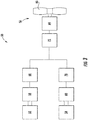
- the exemplary propulsion system 50 includes a first engine 52, a second engine 54, an electric fan assembly 56 and a power bus 62. More specifically, the first engine 52 is coupled to a first generator 58, for driving the first generator 58, and the second engine 54 is coupled to a second generator 60 for driving the second generator 60.
- the first and second engines 52, 54 may be configured as, e.g., turbofan jet engines, turboprop engines, turbojet engines, or any other suitable engine capable of rotating a respective generator.
- the electric fan assembly 56 is electrically coupled to the first and second generators 58, 60 through an electric power bus 62. Additionally, the electric fan assembly 56 generally includes an electric motor 64 and a fan 66, the fan 66 coupled to and being driven by the electric motor 64. The electric motor 64 of the electric fan assembly 56 is electrically coupled to the first and second electric generators 58, 60 through the electric power bus 62.
- the propulsion system 50 may have any other suitable configuration.
- the propulsion system 50 may include any other suitable number of engines and respective generators, and further the electric fan assembly 56 of the propulsion system 50 may have any other suitable number of electric motors and respective fans (e.g., one motor, one generator, and one electric fan; one motor, one generator, and two electric fans; two motors, two generators, and one electric fan; etc.).
- the electric power bus 62 may electrically connect the various components in series, in parallel, or a combination of series in parallel.
- the first and second electric generators 58, 60 may be configured to generate alternating current ("AC") electrical power.
- the electric motor 64 of the electric fan assembly 56 may be configured to operate on AC electrical power.
- the electric power bus 62 may be designed to transmit electrical power in a direct current (“DC") form. Accordingly, the power bus 62 includes power electronics to convert or condition the electrical power transmitted.
- the power bus 62 includes a first AC/DC converter power electronics 68 for receiving AC electrical power from the first generator 58 and converting such AC electrical power to DC electrical power; a second AC/DC converter power electronics 70 for receiving AC electrical power from the second generator 60 and converting such AC electrical power to DC electrical power; and a DC/AC converter power electronics 72 for receiving DC electrical power transmitted through the power bus 62 from the first and second electric generators 58, 60 (converted through the first and second AC/DC converter power electronics 68, 70) and converting such DC electrical power to AC electrical power.
- the power bus 62 further provides such AC electrical power to the electric motor 64 for operating the electric motor 64.
- the power electronics of the power bus 62 may be configured to operate at a relatively high switching frequency, f switch .
- switching frequency refers to the rate at which an inverter or converter of the power electronics is switched on and off when converting DC power to AC power or vice versa.
- the power electronics may be configured to operate at a switching frequency, f switch , between about five (5) kilohertz ("kHz") and about thirty (30) kHz.
- the power electronics may utilize one or more Silicon Carbide (SiC) components.
- SiC Silicon Carbide
- one or more of the inverters, converters, etc. may be formed of Silicon Carbide.
- the propulsion system 50 may include any other suitable configuration.
- the electric motor 64 may operate on the DC electrical power, in which case the propulsion system may not include the DC/AC converter power electronics 72.
- one or both of the generators 58, 60 may be configured to generate DC electrical power, in which case the propulsion system may not include one or both of the first and second AC/DC converter power electronics 68, 70.
- Other configurations are contemplated as well.
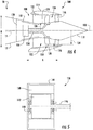
- FIG. 4 a schematic, cross-sectional side view of an electric fan assembly 100 in accordance with various embodiments of the present disclosure is provided.
- the electric fan assembly 100 depicted is configured to be mounted to an aircraft 10 at an aft end 18 of the aircraft 10 and is further configured to ingest a boundary layer air.
- the electric fan assembly 100 is configured as a boundary layer ingestion (BLI), aft fan.
- BLI boundary layer ingestion
- the electric fan assembly 100 may be configured in substantially the same manner as one or more of the electric fan assemblies 56 described above with reference to FIGS. 1 through 3
- the aircraft 10 depicted in FIG. 4 may be configured in substantially the same manner as the exemplary aircraft 10 described above with reference to FIGS. 1 and 2 .
- the electric fan assembly 100 defines an axial direction A extending along a longitudinal centerline axis 102 (or center axis) that extends therethrough for reference, as well as a radial direction R and a circumferential direction C (a direction extending about the axial direction A; not shown). Additionally, the aircraft 10 defines a mean line 15 extending therethrough (see FIG. 4 ).
- the electric fan assembly 100 includes a fan 104 rotatable about the centerline axis 102 and a structural support system 108.
- the structural support system 108 is configured for mounting the electric fan assembly 100 to the aircraft 10, and for the embodiment depicted generally includes an inner frame support 110, a plurality of forward support members 112, an outer nacelle 114, a plurality of aft support members 116, and a tail cone 118.
- the inner frame support 110 is attached to a bulkhead 120 of the fuselage 12.
- the plurality of forward support members 112 are attached to the inner frame support 110 and extend outward generally along the radial direction R to the nacelle 114.
- the nacelle 114 defines an airflow passage 122 with an inner casing 124 of the electric fan assembly 100, and at least partially surrounds the fan 104. Further, for the embodiment depicted, the nacelle 114 extends substantially three hundred and sixty degrees (360°) around the mean line 15 of the aircraft 10.
- the plurality of aft support members 116 also extend, for the embodiment depicted, generally along the radial direction R from, and structurally connect, the nacelle 114 to the tail cone 118.
- the forward support members 112 and the aft support members 116 may each be generally spaced along the circumferential direction C of the electric fan assembly 100. Additionally, in certain embodiments the forward support members 112 may be generally configured as inlet guide vanes and the aft support members 116 may generally be configured as outlet guide vanes. If configured in such a manner, the forward and aft support members 112, 116 may direct and/or condition an airflow through the airflow passage 122 of the electric fan assembly 100. Notably, one or both of the forward support members 112 or aft support members 116 may additionally be configured as variable guide vanes.
- the support member may include a flap (not shown) positioned at an aft end of the support member for directing a flow of air across the support member.
- the structural support system 108 may instead include any other suitable configuration and, e.g., may not include each of the components depicted and described above.
- the electric fan assembly 100 may not include the forward and aft support members 112, 116 or the nacelle 114.
- the structural support system 108 may include any other suitable components not depicted or described above.
- the electric fan assembly 100 additionally defines a nozzle 126 between the nacelle 114 and the tail cone 118.
- the nozzle 126 may be configured to generate an amount of thrust from the air flowing therethrough, and the tail cone 118 may be shaped to minimize an amount of drag on the electric fan assembly 100.
- the tail cone 118 may have any other shape and may, e.g., end forward of an aft end of the nacelle 114 such that the tail cone 118 is enclosed by the nacelle 114 at an aft end.
- the fan 104 includes a plurality of fan blades 128 and a fan shaft 130, with each of the plurality of fan blades 128 defining a tip 132 at an outer end of the respective fan blade 128 along the radial direction R. Additionally, the fan 104 defines a radius 134 equal to a radius of each of the fan blades 128 along the radial direction R from the centerline axis 102 to the tips 132 of the fan blades 128.
- the plurality of fan blades 128 are attached to the fan shaft 130 and spaced generally along the circumferential direction C of the electric fan assembly 100. Moreover, as is depicted the plurality fan blades 128 are, for the embodiment of FIG. 4 , at least partially enclosed by the nacelle 114.
- the plurality of fan blades 128 may be attached in a fixed manner to the fan shaft 130, or alternatively, the plurality of fan blades 128 may be rotatably attached to the fan shaft 130.
- the plurality of fan blades 128 may be attached to the fan shaft 130 such that a pitch of each of the plurality of fan blades 128 may be changed, e.g., in unison, by a pitch change mechanism (not shown). Changing the pitch of the plurality of fan blades 128 may increase an efficiency of the electric fan assembly 100 and/or may allow the electric fan assembly 100 to achieve a desired thrust profile.
- the electric fan assembly 100 may be referred to as a variable pitch fan.
- the fan 104 of the electric fan assembly 100 defines a fan pressure ratio, FPR, during operation, and more particularly during operation at a rated speed.
- FPR fan pressure ratio
- the term "fan pressure ratio” refers to a ratio of a discharge pressure of a fan to an inlet pressure of the fan.
- rated speed refers to a maximum operating speed of the fan during normal operations.
- the electric fan assembly 100 may operate at the rated speed during maximum thrust operations, such as during takeoff operations.
- the fan shaft 130 defines a maximum rotational speed of the fan shaft 130 (i.e., a maximum rotational fan shaft speed, N) and the plurality of fan blades 128 of the fan 104 define a maximum speed at the fan blade tips 132 (i.e., a fan tip speed, U).
- the fan tip speed, U may generally be determined by multiplying the maximum fan shaft speed, N, of the fan shaft 130 by the radius 134 of the fan 104.
- the maximum fan tip speed, U may be a function of the material forming the plurality of fan blades 128 and/or other components of the fan 104.
- the maximum fan tip speed, U may be between about 60,96 meter (200 feet) per second and about 411,48 meter (1350 feet) per second, such as between about 152,4 meter (500 feet) per second and about 304,8 meter (1000 feet) per second.
- the fan 104 is rotatable about the centerline axis 102 of the electric fan assembly 100 by an electric machine. More particularly, the fan 104 is rotatable about the centerline axis 102 by an electric motor 136, the electric motor 136 capable of providing a maximum amount of power (i.e., a maximum amount of power, P, of the electric motor 136) during operation of the electric fan assembly 100 at the rated speed.
- the electric motor 136 is directly connected to the fan 104 through the fan shaft 130. Accordingly, for the embodiment depicted, the electric motor 136 is connected directly to the fan 104 without use of a gearbox or other reduction mechanism. It will therefore be appreciated that the rotational fan shaft speed, N, of the fan shaft 130 will be the same as the rotational speed of the fan 104 and a rotor 142 of the electric motor 136 (described in more detail below).
- the fan 104 of the electric fan assembly 100 further defines a hub radius 138. More specifically, the inner casing 124 of the electric fan assembly 100 defines the hub radius 138.
- the hub radius 138 refers to a distance along the radial direction R from the centerline axis 102 to an outer surface of the inner casing 124 at a forward edge of the plurality of fan blades 128 of the fan 104.
- the electric fan assembly 100 defines a ratio of the hub radius 138 to the fan radius (i.e., fan blade radius 134) between about 0.2 and about 0.4, or more particularly between about 0.25 and about 0.3.
- Such a configuration may allow for, e.g., mounting the electric motor 136 in a desired manner within the inner casing 124.
- FIGS. 5 and 6 cross-sectional views of the electric motor 136 are provided. More particularly, FIG. 5 provides a schematic, side cross-sectional view of the electric motor 136; and FIG. 6 provides a schematic, cross-sectional view of the electric motor 136 along the centerline axis 102.
- the electric motor 136 is generally configured as a synchronous, inrunner electric motor. More particularly, the exemplary electric motor 136 depicted includes a stator 140, a rotor 142 positioned within the stator 140, and an outer casing 144 enclosing the stator 140 and rotor 142.
- the electric motor 136 may instead be configured as an outrunner (or out-running) electric motor, such that a position of the stator 140 and rotor 142 are reversed, and the rotor 142 is instead located radially outside of the stator 140.
- the rotor 142 is mounted to an axle or output shaft 146, which for the embodiment depicted is configured as, or coupled to, the fan shaft 130.
- the electric motor 136 additionally includes a plurality of bearings 148 within the outer casing 144 facilitating rotation of the rotor 142. It should be appreciated, however, that in other exemplary embodiments, the electric motor 136 may instead have any other suitable configuration.
- the stator 140 includes a plurality of electromagnetic coils 150, and the rotor 142 includes a plurality of segmented magnets 152 having alternating magnetic poles 154 (as indicated using the positive sign "+” and negative sign "-" in FIG. 6 ), with each alternating pair of poles 154 together configured as a pole pair.
- the magnets 152 may be permanent magnets, such that the electric motor 136 is a synchronous, permanent magnet electric. Accordingly, it will be appreciated that the electric motor 136 defines a pole count, or number of poles, n poles , equal to the number of poles 154.
- the electric motor 136 defines a number of poles, n poles , equal to thirty six (36). However, in other exemplary embodiments, the electric motor 136 may instead define a number of poles, n poles , between four (4) and about two hundred (200). For example, in other exemplary embodiments, the electric motor 136 may define a number of poles, n poles , between twelve (12) and one hundred and eighty (180).
- the electric motor 136 defines a pole passing frequency, f pass , which is sometimes also referred to as a "fundamental frequency".
- the pole passing frequency, f pass , of the electric motor 136 may be between about 1,500 hertz ("Hz") and about 3,500 Hz.
- the pole passing frequency, f pass , of the electric motor 136 may be between about 1,500 Hz and about 3,500 Hz, such as between about 1,500 Hz and about 2,500 Hz, such as between about 1,800 Hz and about 2,200 Hz, such as about 2,000 Hz.
- An upper limit on the pole passing frequency, f pass , of the electric motor 136 may be a factor of the material forming the electric motor 136, including the rotor 142 and stator 140 of the electric motor 136.
- the electric motor 136 may be formed of an iron-based material, such as an iron-cobalt material.
- the pole passing frequency, f pass , of the electric motor 136 may be between about 1,500 Hz and about 2,500 Hz, such as about 2,000 Hz.
- the electric motor 136 may be formed of an electric steel material.
- the pole passing frequency, f pass , of the electric motor 136 may be between about 2,000 Hz and about 2,700 Hz, such as about 2,250 Hz. Additionally, or alternatively, still, in other embodiments the electric motor 136 may be configured as an air core machine, formed of a resin material or of, e.g., air gaps. With such an embodiment, the pole passing frequency, f pass , of the electric motor 136 may be between about 2,500 Hz and about 3,500 Hz, such as about 3,000 Hz.
- Operating the electric motor 136 within the above identified pole passing frequencies, f pass may ensure the electric motor 136 is operated with a desired power density. For example, operating in excess of the above identified pole passing frequencies, f pass , for a given electric motor 136 may result in diminishing returns in power density and losses in efficiency as a result of increased temperatures and eddy currents. Notably, however, other materials may also be possible for the electric motor 136 and similarly other pole passing frequencies, f pass , may also be possible for the materials described above.
- the electric fan assembly 100 may include a fan 104 being driven by an electric motor 136 via a fan shaft 130.
- the fan 104 may define a fan pressure ratio, FPR, and a fan radius 134.
- the fan 104 may include a plurality of fan blades 128 defining a fan tip speed, U.
- the fan shaft 130 may define a rotational speed, N, and the fan assembly 100, or fan 104, may further define a hub radius 138.
- the graph 200 depicts at line 202 (described in more detail below) a relationship between the fan pressure ratio, FPR, of the fan 104 of the electric fan assembly 100 and an electric motor parameter of the electric fan assembly 100. More specifically, the electric motor parameter is equal to the number of poles, n poles , of the electric motor 136 divided by the square root of the maximum power, P, of the electric motor 136 (in horsepower).
- an electric fan assembly 100 in a propulsion system 50, wherein the fan pressure ratio, FPR, of the electric fan 104 relates to the electric motor parameter (i.e., pole count, n poles , of the electric motor 136 divided by the square root of the maximum power, P, of the electric motor 136) in the manner shown in the graph 200 of FIG. 7 , results in an electric fan assembly having a desired overall efficiency and power density.
- FPR fan pressure ratio
- Equation 1 a maximum power, P, of the electric motor 136.
- P the maximum power of the electric motor 136
- ⁇ the mass flow rate of an airflow through the fan 104
- c p the specific heat of the airflow through the fan 104
- ⁇ T the temperature change of the airflow across the fan 104.
- the inventors of the present disclosure recognized that for a given fan pressure ratio, FPR, the temperature change across the fan 104, ⁇ T, will be constant (assuming operation at constant ambient conditions). Accordingly, from this the inventors determined that the maximum power, P, the electric motor 136 is directly related to the mass flow rate, ⁇ , of the airflow through the fan 104 for a given fan pressure ratio, FPR.
- the mass flow rate, ⁇ , of the airflow through the fan 104 is directly related to a cross-sectional area, A, of the fan 104, which is in turn directly related to a fan radius 134 of the fan 104 squared, r 2 (the fan radius, r, is the same measure as the radius 134 of the fan 104 along the radial direction R, described above with reference to FIG. 4 ).
- the relations of the above parameters are based on a given fan pressure ratio, FPR, meaning that each of these parameters is a function of the fan pressure ratio, FPR.
- Equation 2 may be simplified to Equation 3, below.
- P ⁇ r f FPR
- a fan shaft speed, N is directly related to a fan tip speed, U, divided by the radius, r, of the fan 104.
- a constant fan tip speed, U and substituting the radius, r, of the fan 104 for the square root of the power, P, based on the relationships recognized in Equation 3, allows for the relationship recognized in Equation 4.
- the fan tip speed, U would essentially be a maximum fan tip speed, U, for the desired design, limited by the material properties of the material forming certain components of the fan 104 (see, e.g., discussion above with reference to FIG. 4 ).
- n poles of the electric motor 136 is a function of the pole passing frequency, f pass , over the shaft speed, N. Substituting the shaft speed, N, for one over the square root of power, P, (see Equation 4) allows for the following relationship to be determined in Equation 5. n pole ⁇ f N ⁇ f ⁇ P
- the inventors then assumed a desired pole passing frequency, f pass .
- the electric motor 136 would have a pole passing frequency, f pass , between about 1,500 Hz and about 3,500 Hz, such as between about 1,500 Hz and about 2,500 Hz, such as about 2,000 Hz.
- the power electronics e.g., power electronics 68, 70, 72 utilized with the propulsion system may have a maximum switching frequency, f switch .
- Equation 6 may be written as Equation 7, below, to state that the number of poles, n poles , of the electric motor 136 over the square root of the power, P, of the electric motor 136 is a function of fan pressure ratio, FPR, for an efficient/power dense electric fan assembly.
- n pole P f FPR
- Equation 7 After having distilled that the above parameters are related in the manner shown in Equation 7, the inventors of the present disclosure performed extensive experimentation to confirm the relationship outlined in Equation 7 in fact existed, and further to define what the equation/function was that related fan pressure ratio, FPR, to the number of poles, n poles , divided by the square root of power, P.
- FPR fan pressure ratio
- the inventors of the present disclosure went through numerous examples of potential electric fan assemblies, each example having a set, unique fan pressure ratio, FPR, (e.g., between 1 and 2) and electric motor power, P, (e.g., between 650 hp and 4,500 hp) that would be desirable for the electric fan assembly.
- FPR fan pressure ratio
- P electric motor power
- the inventors of the present disclosure were then able to determine for each example: (a) a resulting RPM for the electric motor 136 (e.g., a rotational shaft speed, N) of the electric fan assembly 100; (b) a resulting hub radius 138 for the electric fan 104; and (c) a resulting pole count, n poles , for the electric motor 136.
- an electric motor parameter equal to the number of poles, n poles , over the square root of power, P, for the electric motor 136.
- FIG. 8 a table is provided showing six of the above-mentioned examples.
- the inventors set the fan pressure ratio, FPR, and electric motor power, P (Columns 1 and 2). Using these values, the assumptions made above, and one or more models, the inventors of the present disclosure were then able to determine for each example, (a) the resulting RPM for the electric motor 136 (e.g., a rotational shaft speed, N) of the electric fan assembly 100 (Column 3); (b) the resulting hub radius 138 for the electric fan 104 (Column 4); and (c) the resulting pole count, n poles , for the electric motor 136 (Column 5).
- the resulting RPM for the electric motor 136 e.g., a rotational shaft speed, N
- the values determined for each of the examples in Column 5, along with the values for each of the examples in Column 2, allowed the inventors to determine the electric motor parameter for each example in Column 6, the electric motor parameter being equal to the number of poles, n poles , over the square root of power, P, for the electric motor 136.
- the fan pressure ratio, FPR values for each example (e.g., the values in Column 1 for the examples depicted in FIG. 8 ) were plotted with the electric motor parameter values for the respective examples (e.g., the values in Column 6 for the examples depicted in FIG. 8 ). Using these plotted values, a line of best fit was then determined. This line of best fit is depicted as the line 202 in the graph 200 of FIG. 7 .
- the electric fan assembly 100 may include an electric motor 136 having a pole passing frequency, f pass , between about 1,500 Hz and about 3,500 Hz.
- the constant C 1 may have a value between 22,000 and 52,000
- the constant, C 2 may have a value between 4.0 and 9.8.
- a lower limit line 204 is provided (with constant, C 1 , being set equal to 22,000 and constant, C 2 , being equal to 4.0) for when the pole passing frequency, f pass , is equal to about 1,500 Hz
- an upper limit line 206 is provided (with the constant, C 1 , being equal to 52,000 and the constant, C 2 , being equal to 9.8) for when the pole passing frequency, f pass , is equal to about 3,500 Hz.
- e is Euler's number (approximately 2.718).
- Equation 8 may rely on certain assumptions for the electric fan assembly 100.
- the formula determined in Equation 8 may rely on a hub radius 138 for the electric fan assembly 100; a fan tip speed, U, of a fan 104 of the electric fan assembly 100; a shaft speed, N, of the electric fan assembly 100; and a pole passing frequency, f pass , of an electric motor 136 of the electric fan assembly 100, as stated.
- a propulsion system including an electric fan assembly in accordance with one or more embodiments of the present disclosure may provide for an electric fan assembly having a maximum efficiency and power density (e.g., an amount of thrust per unit volume of air flowing through the electric fan assembly) for an electric fan assembly having certain design parameters.
- a maximum efficiency and power density e.g., an amount of thrust per unit volume of air flowing through the electric fan assembly
- the propulsion system may be configured in substantially the same manner as one or more of the exemplary propulsion systems described above.
- the propulsion system may include a fan having a plurality of fan blades, as well as an electric motor mechanically coupled to the fan.
- C 1 is a constant having a value between 22,000 and 37,000
- C 2 is a constant having a value between 4.0 and 7.0
- e is Euler's number.
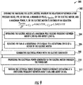
- driving the fan using the electric motor at (302) includes at (304) operating the electric motor at a maximum pole passing frequency between about 1,500 Hz and about 2,500 Hz.
- driving the fan using the electric motor at (302) may include operating the electric motor at a maximum pole passing frequency of about 2,000 Hz.
- the electric fan may be directly mechanically coupled to the electric motor through, e.g., one or more driveshafts or couplings.
- driving the fan using the electric motor at (302) may include at (306) rotating the fan at a rotational speed equal to a rotational speed of a rotor of the electric motor.
- the exemplary propulsion system may additionally include a combustion engine, an electric generator mechanically coupled to the combustion engine, and a power bus electrically connecting the electric generator to the electric motor.
- the method 300 may further include at (308) generating electrical power with the electric generator, and at (310) providing the electrical power generated to the electric motor through the power bus.
- generating electrical power with the electric generator at (308) may include driving the electric generator with the combustion engine, with the combustion engine being, e.g., a turbofan engine, a turboprop engine, turbojet engine, a turboshaft engine, etc.
- providing electrical power generated to the electric motor to the power bus at (310) further includes at (312) passing the electrical power through power electronics operating at a switching frequency between about 5 kilohertz (kHz) and about 30 kHz.
Landscapes
- Engineering & Computer Science (AREA)
- Aviation & Aerospace Engineering (AREA)
- Mechanical Engineering (AREA)
- Chemical & Material Sciences (AREA)
- Combustion & Propulsion (AREA)
- General Engineering & Computer Science (AREA)
- Structures Of Non-Positive Displacement Pumps (AREA)
- Connection Of Motors, Electrical Generators, Mechanical Devices, And The Like (AREA)
Claims (15)
- Système de propulsion aéronautique (50) définissant un axe central et comprenant :un ventilateur (104) ayant une pluralité de pales de ventilateur (128) pouvant tourner autour de l'axe central et définissant un rapport de pression de ventilateur (FPR) ; etun moteur électrique (136) couplé mécaniquement au ventilateur (104) pour entraîner le ventilateur (104), le moteur électrique (136) comprenant un certain nombre de pôles (154) (npôles ) et définissant une puissance maximale (P) ;caractérisé en ce que la relation entre le rapport de pression de ventilateur (FPR) du ventilateur (104), le nombre de pôles (154) (npôles ) du moteur électrique (136) et la puissance maximale (P) du moteur électrique (136) est définie par une équation :
 dans laquelle C 1 est une constante ayant une valeur comprise entre 22 000 et 52 000, dans laquelle C 2 est une constante ayant une valeur comprise entre 4,0 et 9,8, et dans laquelle e est le nombre d'Euler.
 - Système de propulsion aéronautique (50) selon la revendication 1, dans lequel le nombre de pôles (154) (npôles ) est compris entre 4 et 180, dans lequel la puissance maximale (P) est comprise entre 650 et 6 000 chevaux, et dans lequel le rapport de pression du ventilateur (FPR) est compris entre 1 et 2.
- Système de propulsion aéronautique (50) selon l'une quelconque des revendications précédentes, dans lequel le moteur électrique (136) fonctionne à une fréquence maximale de passage de pôles comprise entre environ 1 500 Hertz (« Hz ») et environ 3 500 Hz.
- Système de propulsion aéronautique (50) selon l'une quelconque des revendications précédentes, dans lequel le moteur électrique (136) est connecté directement au ventilateur (104) sans utilisation d'une boîte de vitesses.
- Système de propulsion aéronautique (50) selon l'une quelconque des revendications précédentes, dans lequel le ventilateur (104) et le moteur électrique (136) sont configurés ensemble comme ventilateur d'ingestion de couche limite (104).
- Système de propulsion aéronautique (50) selon l'une quelconque des revendications précédentes, dans lequel le ventilateur (104) et le moteur électrique (136) sont configurés ensemble comme ventilateur arrière (104) conçu pour être monté à l'extrémité arrière d'un aéronef.
- Système de propulsion aéronautique (50) selon l'une quelconque des revendications précédentes, dans lequel le ventilateur (104) définit un rayon de moyeu (138), dans lequel la pluralité de pales de ventilateur (128) définissent un rayon de ventilateur (134), dans lequel un rapport du rayon du moyeu (138) au rayon du ventilateur (134) est compris entre environ 0,2 et environ 0,4.
- Système de propulsion aéronautique (50) selon la revendication 7, dans lequel le rapport du rayon du moyeu (138) au rayon du ventilateur (134) est compris entre environ 0,25 et environ 0,3.
- Système de propulsion aéronautique (50) selon l'une quelconque des revendications précédentes, comprenant en outre :un moteur à combustion ;un générateur électrique couplé mécaniquement au moteur à combustion pour produire de l'énergie électrique ; etun bus de puissance (62) connectant électriquement le générateur électrique au moteur électrique (136), le bus de puissance (62) comprenant une électronique de puissance.
- Système de propulsion aéronautique (50) selon la revendication 9, dans lequel l'électronique de puissance utilise un ou plusieurs composants en carbure de silicium.
- Système de propulsion aéronautique (50) selon la revendication 9 ou 10, dans lequel l'électronique de puissance est configurée pour fonctionner à une fréquence de commutation comprise entre environ 5 kilohertz (kHz) et environ 30 kHz.
- Système de propulsion aéronautique (50) selon l'une quelconque des revendications précédentes, dans lequel le ventilateur (104) définit une vitesse maximale d'extrémité de ventilateur et dans lequel la vitesse maximale d'extrémité de ventilateur est comprise entre environ 60,96 mètres par seconde et environ 411,48 mètres par seconde.
- Procédé (300) permettant de faire fonctionner un système de propulsion d'un aéronef, le système de propulsion comprenant un ventilateur ayant une pluralité de pales de ventilateur et un moteur électrique couplé mécaniquement au ventilateur, le procédé (300) consistant à :
entraîner le ventilateur à l'aide du moteur électrique (302), la relation entre un rapport de pression de ventilateur (FPR) du ventilateur, un certain nombre de pôles (npôles ) du moteur électrique, et une puissance maximale (P) du moteur électrique étant définie par une équation :
- Procédé (300) selon la revendication 13, dans lequel l'entraînement du ventilateur à l'aide du moteur électrique (302) consiste à faire fonctionner le moteur électrique à une fréquence maximale de passage de pôles comprise entre environ 1 500 Hertz (« Hz ») et environ 3 500 Hz (304).
- Procédé (300) selon l'une des revendications 13 ou 14, dans lequel l'entraînement du ventilateur à l'aide du moteur électrique (302) consiste à faire tourner le ventilateur à une vitesse de rotation égale à une vitesse de rotation d'un rotor du moteur électrique (306).
Applications Claiming Priority (1)
| Application Number | Priority Date | Filing Date | Title |
|---|---|---|---|
| US15/475,401 US10137981B2 (en) | 2017-03-31 | 2017-03-31 | Electric propulsion system for an aircraft |
Publications (2)
| Publication Number | Publication Date |
|---|---|
| EP3381797A1 EP3381797A1 (fr) | 2018-10-03 |
| EP3381797B1 true EP3381797B1 (fr) | 2020-01-08 |
Family
ID=61800333
Family Applications (1)
| Application Number | Title | Priority Date | Filing Date |
|---|---|---|---|
| EP18163637.4A Active EP3381797B1 (fr) | 2017-03-31 | 2018-03-23 | Système de propulsion électrique pour un aéronef |
Country Status (6)
| Country | Link |
|---|---|
| US (1) | US10137981B2 (fr) |
| EP (1) | EP3381797B1 (fr) |
| JP (1) | JP6560391B2 (fr) |
| CN (1) | CN108688822B (fr) |
| BR (1) | BR102018004832A2 (fr) |
| CA (1) | CA2998931C (fr) |
Families Citing this family (27)
| Publication number | Priority date | Publication date | Assignee | Title |
|---|---|---|---|---|
| US9303589B2 (en) | 2012-11-28 | 2016-04-05 | Pratt & Whitney Canada Corp. | Low hub-to-tip ratio fan for a turbofan gas turbine engine |
| CN109229361A (zh) * | 2017-07-11 | 2019-01-18 | 深圳市道通智能航空技术有限公司 | 电机控制系统及无人机 |
| GB201818687D0 (en) | 2018-11-16 | 2019-01-02 | Rolls Royce Plc | Boundary layer ingestion fan system |
| GB201818683D0 (en) | 2018-11-16 | 2019-01-02 | Rolls Royce Plc | Boundary layer ingestion fan system |
| GB201818681D0 (en) | 2018-11-16 | 2019-01-02 | Rolls Royce Plc | Boundary layer ingestion fan system |
| GB201818686D0 (en) | 2018-11-16 | 2019-01-02 | Rolls Royce Plc | Boundary layer ingestion fan system |
| GB201818684D0 (en) | 2018-11-16 | 2019-01-02 | Rolls Royce Plc | Boundary layer ingestion fan system |
| GB201818682D0 (en) | 2018-11-16 | 2019-01-02 | Rolls Royce Plc | Boundary layer ingestion fan system |
| GB201818680D0 (en) | 2018-11-16 | 2019-01-02 | Rolls Royce Plc | Boundary layer ingestion fan system |
| US10968765B2 (en) * | 2018-12-04 | 2021-04-06 | General Electric Company | Power system with a coordinated power draw |
| EP3931102A4 (fr) | 2019-03-01 | 2022-11-16 | Pratt & Whitney Canada Corp. | Indicateurs pour groupes motopropulseurs électriques hybrides |
| WO2020180368A2 (fr) * | 2019-03-01 | 2020-09-10 | United Technologies Advanced Projects, Inc. | Aéronef pourvu d'un système de propulsion hybride-électrique comprenant un dispositif d'accumulation électrique situé dans le fuselage |
| CA3132288A1 (fr) | 2019-03-01 | 2020-09-17 | Pratt & Whitney Canada Corp. | Fonctionnement en mode normal de systemes de propulsion electrique hybrides |
| WO2020180372A2 (fr) | 2019-03-01 | 2020-09-10 | United Technologies Advanced Projects, Inc. | Fonctionnement en mode dégradé de systèmes de propulsion électrique hybrides |
| CA3134499A1 (fr) | 2019-04-25 | 2020-10-29 | Pratt & Whitney Canada Corp. | Systemes de commande pour centrales electriques hybrides |
| US11655043B2 (en) | 2019-05-16 | 2023-05-23 | Duxion Motors, Inc. | Electric aircraft propulsion system |
| SG11202112597XA (en) * | 2019-05-16 | 2021-12-30 | Duxion Motors Inc | Electric aircraft propulsion system |
| US12421892B2 (en) | 2019-12-04 | 2025-09-23 | Rolls-Royce North American Technologies Inc. | Hybrid turbine engine with selective electrical module engagement |
| CN113054802A (zh) * | 2019-12-26 | 2021-06-29 | 通用电气公司 | 具有适形热管组件的电动马达 |
| US11958622B2 (en) | 2020-05-15 | 2024-04-16 | Pratt & Whitney Canada Corp. | Protection functions |
| US11794917B2 (en) | 2020-05-15 | 2023-10-24 | Pratt & Whitney Canada Corp. | Parallel control loops for hybrid electric aircraft |
| US12404030B2 (en) * | 2020-08-31 | 2025-09-02 | General Electric Company | Propulsion system for an aircraft |
| CA3212127A1 (fr) * | 2021-03-03 | 2022-09-09 | Whisper Aero Inc. | Ventilateur de propulseur et systeme d'entrainement |
| US11649060B2 (en) * | 2021-09-14 | 2023-05-16 | Beta Air, Llc | Method and system for propulsion in an electric aircraft |
| US11572827B1 (en) * | 2021-10-15 | 2023-02-07 | General Electric Company | Unducted propulsion system |
| US11692513B2 (en) * | 2021-11-01 | 2023-07-04 | Yuriy Radzikh | Electric jet engine |
| EP4420986A3 (fr) * | 2022-02-10 | 2024-10-30 | Lilium eAircraft GmbH | Moteur d'avion électrique |
Family Cites Families (91)
| Publication number | Priority date | Publication date | Assignee | Title |
|---|---|---|---|---|
| US2812912A (en) | 1953-08-06 | 1957-11-12 | Northrop Aircraft Inc | Inclined engine installation for jet aircraft |
| US3286470A (en) | 1963-11-14 | 1966-11-22 | Gen Electric | Tip-turbine fan with thrust reverser |
| US3312448A (en) | 1965-03-01 | 1967-04-04 | Gen Electric | Seal arrangement for preventing leakage of lubricant in gas turbine engines |
| US3844110A (en) | 1973-02-26 | 1974-10-29 | Gen Electric | Gas turbine engine internal lubricant sump venting and pressurization system |
| US4089493A (en) | 1976-09-29 | 1978-05-16 | Paulson Allen E | Aircraft with combination power plant |
| US4605185A (en) | 1983-10-17 | 1986-08-12 | Daniel Reyes | Airplane powered by vehicular motor |
| US4913380A (en) | 1988-10-13 | 1990-04-03 | Omac, Inc. | Fuel system for Canard aircraft |
| DE19633209A1 (de) | 1995-08-28 | 1997-03-06 | Papst Motoren Gmbh & Co Kg | Verfahren und Vorrichtung zur Reduzierung des sogenannten Nutruckens bei einem Elektromotor |
| US5927644A (en) | 1997-10-08 | 1999-07-27 | General Electric Company | Double failsafe engine mount |
| US6619030B1 (en) * | 2002-03-01 | 2003-09-16 | General Electric Company | Aircraft engine with inter-turbine engine frame supported counter rotating low pressure turbine rotors |
| GB2394991B (en) | 2002-11-06 | 2006-02-15 | Rolls Royce Plc | Mounting arrangement |
| US7387189B2 (en) | 2003-08-14 | 2008-06-17 | United Technologies Corp. | Emergency lubrication system |
| US6982533B2 (en) | 2003-09-17 | 2006-01-03 | Rockwell Automation Technologies, Inc. | Method and apparatus to regulate loads |
| FR2873096B1 (fr) | 2004-07-15 | 2007-11-23 | Airbus France Sas | Avion multimoteur |
| GB0418454D0 (en) | 2004-08-19 | 2004-09-22 | Rolls Royce Plc | An engine mounting assembly |
| US7976273B2 (en) | 2004-12-01 | 2011-07-12 | United Technologies Corporation | Tip turbine engine support structure |
| WO2006059978A1 (fr) | 2004-12-01 | 2006-06-08 | United Technologies Corporation | Moteur a turbine de bout en porte-a-faux |
| US7267300B2 (en) | 2005-02-25 | 2007-09-11 | The Boeing Company | Aircraft capable of vertical and short take-off and landing |
| US7493754B2 (en) | 2005-10-19 | 2009-02-24 | General Electric Company | Gas turbine engine assembly and methods of assembling same |
| US7423394B2 (en) | 2006-01-12 | 2008-09-09 | Intelasense, Llc | Single-sensor based commutation of multi-phase motor |
| FR2899200B1 (fr) | 2006-03-28 | 2008-11-07 | Airbus France Sas | Aeronef a impact environnemental reduit |
| FR2903666B1 (fr) | 2006-07-11 | 2008-10-10 | Airbus France Sas | Ensemble moteur pour aeronef comprenant un capotage aerodynamique de jonction monte sur deux elements distincts |
| US7752834B2 (en) | 2006-10-25 | 2010-07-13 | United Technologies Corporation | Aircraft propulsion systems |
| US7665689B2 (en) | 2006-11-24 | 2010-02-23 | The Boeing Company | Unconventional integrated propulsion systems and methods for blended wing body aircraft |
| DE102006056354B4 (de) | 2006-11-29 | 2013-04-11 | Airbus Operations Gmbh | Hybridantrieb für ein Flugzeug |
| US7622817B2 (en) | 2006-12-13 | 2009-11-24 | General Electric Company | High-speed high-pole count generators |
| US7770381B2 (en) * | 2006-12-18 | 2010-08-10 | General Electric Company | Duct burning mixed flow turbofan and method of operation |
| US7877980B2 (en) * | 2006-12-28 | 2011-02-01 | General Electric Company | Convertible gas turbine engine |
| DE102007055336A1 (de) | 2007-01-15 | 2008-08-21 | GIF Gesellschaft für Industrieforschung mbH | Flugzeugpropellerantrieb, Verfahren zum Antreiben eines Flugzeugpropellers und Verwendung eines Lagers eines Flugzeugpropellerantriebs sowie Verwendung einer Elektromaschine |
| US8727271B2 (en) | 2008-01-11 | 2014-05-20 | Ival O. Salyer | Aircraft using turbo-electric hybrid propulsion system |
| FR2928137B1 (fr) | 2008-02-29 | 2010-08-20 | Airbus France | Systeme de propulsion arriere d'avion fixe par poutres et avion comportant un tel systeme. |
| CZ300681B6 (cs) | 2008-08-20 | 2009-07-15 | Vycítal@Jirí | Hybridní pohon letadla |
| US8226040B2 (en) | 2008-08-25 | 2012-07-24 | Embraer S.A. | Continuous fuel management system for automatic control of aircraft center of gravity |
| DE102008048915B4 (de) | 2008-09-26 | 2017-05-18 | Airbus Operations Gmbh | Leistungsverteilungssystem |
| US8099944B2 (en) | 2008-10-08 | 2012-01-24 | The Invention Science Fund I, Llc | Hybrid propulsive engine including at least one independently rotatable propeller/fan |
| US20100108806A1 (en) | 2008-10-08 | 2010-05-06 | Searete Llc, A Limited Liability Corporation Of The State Of Delaware | Hybrid propulsive engine including at least one independently rotatable propeller/fan |
| US8128019B2 (en) | 2008-12-12 | 2012-03-06 | Honeywell International Inc. | Hybrid power for ducted fan unmanned aerial systems |
| US8469306B2 (en) | 2009-01-27 | 2013-06-25 | Ira F. Kuhn, Jr. | Purebred and hybrid electric VTOL tilt rotor aircraft |
| US20100207478A1 (en) * | 2009-02-06 | 2010-08-19 | D-Star Engineering Corporation | Tip-located axial-gap (tag) motor/generator |
| FR2945268B1 (fr) | 2009-05-05 | 2013-05-17 | Airbus France | Generateur electrique sur une partie tournante de turbopropulseur |
| GB0909158D0 (en) | 2009-05-29 | 2009-07-08 | Rolls Royce Plc | An aircraft having a lift/propulsion unit |
| US8622687B2 (en) * | 2009-09-25 | 2014-01-07 | General Electric Company | Method of operating adaptive core engines |
| DE102010014637B4 (de) | 2010-04-12 | 2016-05-04 | MTU Aero Engines AG | Verfahren zum Konservieren eines Kraftstoffsystems und eines Ölsystems |
| DE102010021022A1 (de) | 2010-05-19 | 2011-11-24 | Eads Deutschland Gmbh | Kippflügel-Flugzeug |
| US8294409B2 (en) | 2010-08-18 | 2012-10-23 | Hamilton Sundstrand Corporation | Control of pole-change induction motors |
| US9702254B2 (en) | 2010-09-14 | 2017-07-11 | Manuel M. Saiz | Lift propulsion and stabilizing system and procedure for vertical take-off and landing aircraft |
| US8684304B2 (en) | 2010-11-16 | 2014-04-01 | Rolls-Royce Corporation | Aircraft, propulsion system, and system for taxiing an aircraft |
| US8727270B2 (en) | 2010-11-16 | 2014-05-20 | Rolls-Royce Corporation | Aircraft, propulsion system, and system for taxiing an aircraft |
| US9212625B2 (en) | 2010-11-19 | 2015-12-15 | Rudolph Allen SHELLEY | Hybrid gas turbine propulsion system |
| US20120209456A1 (en) | 2011-02-15 | 2012-08-16 | Government Of The United States, As Represented By The Secretary Of The Air Force | Parallel Hybrid-Electric Propulsion Systems for Unmanned Aircraft |
| GB201104733D0 (en) | 2011-03-21 | 2011-05-04 | Lee Christopher J | Charging unit for hybrid electrically powered aircraft |
| US8552575B2 (en) | 2011-04-03 | 2013-10-08 | Tma Power, Llc | Hybrid electric power for vehicular propulsion |
| US9540998B2 (en) | 2011-05-27 | 2017-01-10 | Daniel K. Schlak | Integral gas turbine, flywheel, generator, and method for hybrid operation thereof |
| FR2977030B1 (fr) | 2011-06-22 | 2013-07-12 | Airbus Operations Sas | Procede d'equilibrage pour systeme propulsif a helices contrarotatives coaxiales non carenees |
| FR2978124B1 (fr) | 2011-07-18 | 2013-08-02 | Eurocopter France | Procede de controle d'un groupe de moteurs et aeronef |
| FR2978728B1 (fr) | 2011-08-03 | 2014-07-04 | Eads Europ Aeronautic Defence | Architecture de propulsion d'aeronef integrant un systeme de recuperation d'energie |
| US8500064B2 (en) | 2011-08-10 | 2013-08-06 | Hamilton Sundstrand Corporation | Hybrid power system architecture for an aircraft |
| US9828105B2 (en) | 2011-08-24 | 2017-11-28 | United Technologies Corporation | Nacelle assembly having integrated afterbody mount case |
| US20130062885A1 (en) | 2011-09-08 | 2013-03-14 | General Electric Company | Method and apparatus for extracting electrical power from a gas turbine engine |
| GB201117104D0 (en) | 2011-10-05 | 2011-11-16 | Rolls Royce Plc | A duct |
| US8723349B2 (en) | 2011-10-07 | 2014-05-13 | General Electric Company | Apparatus for generating power from a turbine engine |
| US8723385B2 (en) | 2011-10-07 | 2014-05-13 | General Electric Company | Generator |
| US9038398B2 (en) | 2012-02-27 | 2015-05-26 | United Technologies Corporation | Gas turbine engine buffer cooling system |
| US9102326B2 (en) | 2012-03-05 | 2015-08-11 | Embry-Riddle Aeronautical University, Inc. | Hybrid assembly for an aircraft |
| US9340299B2 (en) | 2012-03-30 | 2016-05-17 | W. Morrison Consulting Group, Inc. | Long range electric aircraft and method of operating same |
| US9296288B2 (en) | 2012-05-07 | 2016-03-29 | Separation Design Group Llc | Hybrid radiant energy aircraft engine |
| DE102012209807A1 (de) | 2012-06-12 | 2013-12-12 | Siemens Aktiengesellschaft | Flugzeug und Verfahren zum Herstellen eines Flugzeugs |
| CA2820254C (fr) | 2012-07-09 | 2020-02-18 | Mcmaster University | Systeme de groupe propulseur hybride |
| FR2993727B1 (fr) | 2012-07-19 | 2017-07-21 | Eurocopter France | Machine electrique reversible pour aeronef |
| US8939399B2 (en) | 2012-07-31 | 2015-01-27 | Textron Innovations Inc. | System and method of augmenting power in a rotorcraft |
| FR2997681B1 (fr) | 2012-11-08 | 2015-05-15 | Snecma | Avion propulse par un turboreacteur a soufflantes contrarotatives |
| EP2964530B1 (fr) | 2013-03-09 | 2019-10-30 | Rolls-Royce Corporation | Groupe motopropulseur d'avion |
| FR3003514B1 (fr) | 2013-03-25 | 2016-11-18 | Eurocopter France | Aeronef a voilure tournante a motorisation hybride. |
| US9193451B2 (en) | 2013-04-22 | 2015-11-24 | Ival O. Salyer | Aircraft using turbo-electric hybrid propulsion system for multi-mode operation |
| US10144524B2 (en) | 2013-06-14 | 2018-12-04 | Rohr, Inc. | Assembly for mounting a turbine engine to a pylon |
| FR3006997B1 (fr) | 2013-06-14 | 2016-12-23 | Airbus | Aeronef a moyens de propulsion electriques |
| CN105765816A (zh) * | 2013-10-04 | 2016-07-13 | 通用电气航空系统有限责任公司 | 用于飞行器的配电系统 |
| US9162669B2 (en) | 2014-02-25 | 2015-10-20 | Cummins Inc. | Systems and methods for control of powertrains with regenerative start/stop alternator functionality |
| CA2891864A1 (fr) * | 2014-05-30 | 2015-11-30 | Daniel Alan NIERGARTH | Rotor a pas variable dote de contrepoids eloignes |
| BR102015015377B1 (pt) * | 2014-06-27 | 2022-04-26 | United Technologies Corporation | Conjunto de motor de turbina a gás, e, sistema de controle ambiental de uma aeronave |
| US10381889B2 (en) | 2014-06-27 | 2019-08-13 | General Electric Company | Permanent magnet machine with segmented sleeve for magnets |
| US10000293B2 (en) * | 2015-01-23 | 2018-06-19 | General Electric Company | Gas-electric propulsion system for an aircraft |
| US9951719B2 (en) * | 2015-04-13 | 2018-04-24 | United Technologies Corporation | Combined inlet laminar and thrust reverser cascade efflux flow control system |
| JP6730842B2 (ja) * | 2015-05-05 | 2020-07-29 | ロールス−ロイス コーポレイション | 航空機の推進およびリフトのための電気直結駆動装置 |
| GB201508139D0 (en) * | 2015-05-13 | 2015-06-24 | Rolls Royce Plc | Aircraft propulsion system |
| GB201511033D0 (en) | 2015-05-19 | 2015-08-05 | Rolls Royce Plc | Aircraft electrical network |
| EP3124379B1 (fr) * | 2015-07-29 | 2019-05-01 | Airbus Defence and Space GmbH | Chaine cinematique hybride-electrique pour drones vtol |
| US9637217B2 (en) * | 2015-09-21 | 2017-05-02 | General Electric Company | Aircraft having an aft engine |
| US10252810B2 (en) * | 2016-04-19 | 2019-04-09 | General Electric Company | Propulsion engine for an aircraft |
| US20180080411A1 (en) * | 2016-09-16 | 2018-03-22 | General Electric Company | Gas turbine engine |
| US10677264B2 (en) * | 2016-10-14 | 2020-06-09 | General Electric Company | Supersonic single-stage turbofan engine |
-
2017
- 2017-03-31 US US15/475,401 patent/US10137981B2/en active Active
-
2018
- 2018-03-12 BR BR102018004832-5A patent/BR102018004832A2/pt not_active IP Right Cessation
- 2018-03-22 CA CA2998931A patent/CA2998931C/fr active Active
- 2018-03-23 EP EP18163637.4A patent/EP3381797B1/fr active Active
- 2018-03-29 JP JP2018063948A patent/JP6560391B2/ja active Active
- 2018-03-30 CN CN201810289689.2A patent/CN108688822B/zh active Active
Non-Patent Citations (1)
| Title |
|---|
| None * |
Also Published As
| Publication number | Publication date |
|---|---|
| CA2998931A1 (fr) | 2018-09-30 |
| EP3381797A1 (fr) | 2018-10-03 |
| US20180281931A1 (en) | 2018-10-04 |
| BR102018004832A2 (pt) | 2018-12-04 |
| CA2998931C (fr) | 2019-09-17 |
| JP2018188135A (ja) | 2018-11-29 |
| CN108688822B (zh) | 2021-11-16 |
| JP6560391B2 (ja) | 2019-08-14 |
| CN108688822A (zh) | 2018-10-23 |
| US10137981B2 (en) | 2018-11-27 |
Similar Documents
| Publication | Publication Date | Title |
|---|---|---|
| EP3381797B1 (fr) | Système de propulsion électrique pour un aéronef | |
| US20240092494A1 (en) | Propulsion System for an Aircraft | |
| EP3236058B1 (fr) | Procédé d'opération d'un moteur de propulsion pour aéronef | |
| CN108928493B (zh) | 用于飞行器的推进系统及其操作方法 | |
| CN109071030B (zh) | 用于飞行器的推进发动机 | |
| EP3048042B1 (fr) | Système de propulsion gaz-électrique pour un avion | |
| EP3392149B1 (fr) | Système de propulsion pour aéronef | |
| EP3403932B1 (fr) | Système de propulsion pour un aéronef | |
| EP3659908A1 (fr) | Système de gestion thermique de moteur à propulsion | |
| EP3216698A1 (fr) | Système de propulsion pour aéronef | |
| CN119696440A (zh) | 电机组件及其操作方法 |
Legal Events
| Date | Code | Title | Description |
|---|---|---|---|
| PUAI | Public reference made under article 153(3) epc to a published international application that has entered the european phase |
Free format text: ORIGINAL CODE: 0009012 |
|
| STAA | Information on the status of an ep patent application or granted ep patent |
Free format text: STATUS: THE APPLICATION HAS BEEN PUBLISHED |
|
| AK | Designated contracting states |
Kind code of ref document: A1 Designated state(s): AL AT BE BG CH CY CZ DE DK EE ES FI FR GB GR HR HU IE IS IT LI LT LU LV MC MK MT NL NO PL PT RO RS SE SI SK SM TR |
|
| AX | Request for extension of the european patent |
Extension state: BA ME |
|
| STAA | Information on the status of an ep patent application or granted ep patent |
Free format text: STATUS: REQUEST FOR EXAMINATION WAS MADE |
|
| 17P | Request for examination filed |
Effective date: 20190403 |
|
| RBV | Designated contracting states (corrected) |
Designated state(s): AL AT BE BG CH CY CZ DE DK EE ES FI FR GB GR HR HU IE IS IT LI LT LU LV MC MK MT NL NO PL PT RO RS SE SI SK SM TR |
|
| RIC1 | Information provided on ipc code assigned before grant |
Ipc: F02K 5/00 20060101ALI20190516BHEP Ipc: F01D 15/10 20060101ALI20190516BHEP Ipc: B64D 27/18 20060101ALI20190516BHEP Ipc: B64D 27/02 20060101ALI20190516BHEP Ipc: B64D 27/24 20060101ALI20190516BHEP Ipc: B64C 21/06 20060101AFI20190516BHEP |
|
| GRAP | Despatch of communication of intention to grant a patent |
Free format text: ORIGINAL CODE: EPIDOSNIGR1 |
|
| STAA | Information on the status of an ep patent application or granted ep patent |
Free format text: STATUS: GRANT OF PATENT IS INTENDED |
|
| INTG | Intention to grant announced |
Effective date: 20190724 |
|
| GRAS | Grant fee paid |
Free format text: ORIGINAL CODE: EPIDOSNIGR3 |
|
| GRAA | (expected) grant |
Free format text: ORIGINAL CODE: 0009210 |
|
| STAA | Information on the status of an ep patent application or granted ep patent |
Free format text: STATUS: THE PATENT HAS BEEN GRANTED |
|
| AK | Designated contracting states |
Kind code of ref document: B1 Designated state(s): AL AT BE BG CH CY CZ DE DK EE ES FI FR GB GR HR HU IE IS IT LI LT LU LV MC MK MT NL NO PL PT RO RS SE SI SK SM TR |
|
| REG | Reference to a national code |
Ref country code: GB Ref legal event code: FG4D |
|
| REG | Reference to a national code |
Ref country code: CH Ref legal event code: EP |
|
| REG | Reference to a national code |
Ref country code: DE Ref legal event code: R096 Ref document number: 602018001951 Country of ref document: DE |
|
| REG | Reference to a national code |
Ref country code: IE Ref legal event code: FG4D |
|
| REG | Reference to a national code |
Ref country code: AT Ref legal event code: REF Ref document number: 1222383 Country of ref document: AT Kind code of ref document: T Effective date: 20200215 |
|
| REG | Reference to a national code |
Ref country code: NL Ref legal event code: MP Effective date: 20200108 |
|
| REG | Reference to a national code |
Ref country code: LT Ref legal event code: MG4D |
|
| PG25 | Lapsed in a contracting state [announced via postgrant information from national office to epo] |
Ref country code: PT Free format text: LAPSE BECAUSE OF FAILURE TO SUBMIT A TRANSLATION OF THE DESCRIPTION OR TO PAY THE FEE WITHIN THE PRESCRIBED TIME-LIMIT Effective date: 20200531 Ref country code: LT Free format text: LAPSE BECAUSE OF FAILURE TO SUBMIT A TRANSLATION OF THE DESCRIPTION OR TO PAY THE FEE WITHIN THE PRESCRIBED TIME-LIMIT Effective date: 20200108 Ref country code: NL Free format text: LAPSE BECAUSE OF FAILURE TO SUBMIT A TRANSLATION OF THE DESCRIPTION OR TO PAY THE FEE WITHIN THE PRESCRIBED TIME-LIMIT Effective date: 20200108 Ref country code: FI Free format text: LAPSE BECAUSE OF FAILURE TO SUBMIT A TRANSLATION OF THE DESCRIPTION OR TO PAY THE FEE WITHIN THE PRESCRIBED TIME-LIMIT Effective date: 20200108 Ref country code: RS Free format text: LAPSE BECAUSE OF FAILURE TO SUBMIT A TRANSLATION OF THE DESCRIPTION OR TO PAY THE FEE WITHIN THE PRESCRIBED TIME-LIMIT Effective date: 20200108 Ref country code: NO Free format text: LAPSE BECAUSE OF FAILURE TO SUBMIT A TRANSLATION OF THE DESCRIPTION OR TO PAY THE FEE WITHIN THE PRESCRIBED TIME-LIMIT Effective date: 20200408 |
|
| PG25 | Lapsed in a contracting state [announced via postgrant information from national office to epo] |
Ref country code: GR Free format text: LAPSE BECAUSE OF FAILURE TO SUBMIT A TRANSLATION OF THE DESCRIPTION OR TO PAY THE FEE WITHIN THE PRESCRIBED TIME-LIMIT Effective date: 20200409 Ref country code: BG Free format text: LAPSE BECAUSE OF FAILURE TO SUBMIT A TRANSLATION OF THE DESCRIPTION OR TO PAY THE FEE WITHIN THE PRESCRIBED TIME-LIMIT Effective date: 20200408 Ref country code: HR Free format text: LAPSE BECAUSE OF FAILURE TO SUBMIT A TRANSLATION OF THE DESCRIPTION OR TO PAY THE FEE WITHIN THE PRESCRIBED TIME-LIMIT Effective date: 20200108 Ref country code: IS Free format text: LAPSE BECAUSE OF FAILURE TO SUBMIT A TRANSLATION OF THE DESCRIPTION OR TO PAY THE FEE WITHIN THE PRESCRIBED TIME-LIMIT Effective date: 20200508 Ref country code: LV Free format text: LAPSE BECAUSE OF FAILURE TO SUBMIT A TRANSLATION OF THE DESCRIPTION OR TO PAY THE FEE WITHIN THE PRESCRIBED TIME-LIMIT Effective date: 20200108 Ref country code: SE Free format text: LAPSE BECAUSE OF FAILURE TO SUBMIT A TRANSLATION OF THE DESCRIPTION OR TO PAY THE FEE WITHIN THE PRESCRIBED TIME-LIMIT Effective date: 20200108 |
|
| REG | Reference to a national code |
Ref country code: DE Ref legal event code: R097 Ref document number: 602018001951 Country of ref document: DE |
|
| PG25 | Lapsed in a contracting state [announced via postgrant information from national office to epo] |
Ref country code: RO Free format text: LAPSE BECAUSE OF FAILURE TO SUBMIT A TRANSLATION OF THE DESCRIPTION OR TO PAY THE FEE WITHIN THE PRESCRIBED TIME-LIMIT Effective date: 20200108 Ref country code: DK Free format text: LAPSE BECAUSE OF FAILURE TO SUBMIT A TRANSLATION OF THE DESCRIPTION OR TO PAY THE FEE WITHIN THE PRESCRIBED TIME-LIMIT Effective date: 20200108 Ref country code: EE Free format text: LAPSE BECAUSE OF FAILURE TO SUBMIT A TRANSLATION OF THE DESCRIPTION OR TO PAY THE FEE WITHIN THE PRESCRIBED TIME-LIMIT Effective date: 20200108 Ref country code: SM Free format text: LAPSE BECAUSE OF FAILURE TO SUBMIT A TRANSLATION OF THE DESCRIPTION OR TO PAY THE FEE WITHIN THE PRESCRIBED TIME-LIMIT Effective date: 20200108 Ref country code: MC Free format text: LAPSE BECAUSE OF FAILURE TO SUBMIT A TRANSLATION OF THE DESCRIPTION OR TO PAY THE FEE WITHIN THE PRESCRIBED TIME-LIMIT Effective date: 20200108 Ref country code: ES Free format text: LAPSE BECAUSE OF FAILURE TO SUBMIT A TRANSLATION OF THE DESCRIPTION OR TO PAY THE FEE WITHIN THE PRESCRIBED TIME-LIMIT Effective date: 20200108 Ref country code: CZ Free format text: LAPSE BECAUSE OF FAILURE TO SUBMIT A TRANSLATION OF THE DESCRIPTION OR TO PAY THE FEE WITHIN THE PRESCRIBED TIME-LIMIT Effective date: 20200108 Ref country code: SK Free format text: LAPSE BECAUSE OF FAILURE TO SUBMIT A TRANSLATION OF THE DESCRIPTION OR TO PAY THE FEE WITHIN THE PRESCRIBED TIME-LIMIT Effective date: 20200108 |
|
| PLBE | No opposition filed within time limit |
Free format text: ORIGINAL CODE: 0009261 |
|
| STAA | Information on the status of an ep patent application or granted ep patent |
Free format text: STATUS: NO OPPOSITION FILED WITHIN TIME LIMIT |
|
| REG | Reference to a national code |
Ref country code: AT Ref legal event code: MK05 Ref document number: 1222383 Country of ref document: AT Kind code of ref document: T Effective date: 20200108 |
|
| 26N | No opposition filed |
Effective date: 20201009 |
|
| REG | Reference to a national code |
Ref country code: BE Ref legal event code: MM Effective date: 20200331 |
|
| PG25 | Lapsed in a contracting state [announced via postgrant information from national office to epo] |
Ref country code: LU Free format text: LAPSE BECAUSE OF NON-PAYMENT OF DUE FEES Effective date: 20200323 |
|
| PG25 | Lapsed in a contracting state [announced via postgrant information from national office to epo] |
Ref country code: IT Free format text: LAPSE BECAUSE OF FAILURE TO SUBMIT A TRANSLATION OF THE DESCRIPTION OR TO PAY THE FEE WITHIN THE PRESCRIBED TIME-LIMIT Effective date: 20200108 Ref country code: AT Free format text: LAPSE BECAUSE OF FAILURE TO SUBMIT A TRANSLATION OF THE DESCRIPTION OR TO PAY THE FEE WITHIN THE PRESCRIBED TIME-LIMIT Effective date: 20200108 Ref country code: IE Free format text: LAPSE BECAUSE OF NON-PAYMENT OF DUE FEES Effective date: 20200323 |
|
| PG25 | Lapsed in a contracting state [announced via postgrant information from national office to epo] |
Ref country code: SI Free format text: LAPSE BECAUSE OF FAILURE TO SUBMIT A TRANSLATION OF THE DESCRIPTION OR TO PAY THE FEE WITHIN THE PRESCRIBED TIME-LIMIT Effective date: 20200108 Ref country code: PL Free format text: LAPSE BECAUSE OF FAILURE TO SUBMIT A TRANSLATION OF THE DESCRIPTION OR TO PAY THE FEE WITHIN THE PRESCRIBED TIME-LIMIT Effective date: 20200108 Ref country code: BE Free format text: LAPSE BECAUSE OF NON-PAYMENT OF DUE FEES Effective date: 20200331 |
|
| REG | Reference to a national code |
Ref country code: CH Ref legal event code: PL |
|
| PG25 | Lapsed in a contracting state [announced via postgrant information from national office to epo] |
Ref country code: CH Free format text: LAPSE BECAUSE OF NON-PAYMENT OF DUE FEES Effective date: 20210331 Ref country code: LI Free format text: LAPSE BECAUSE OF NON-PAYMENT OF DUE FEES Effective date: 20210331 |
|
| PG25 | Lapsed in a contracting state [announced via postgrant information from national office to epo] |
Ref country code: TR Free format text: LAPSE BECAUSE OF FAILURE TO SUBMIT A TRANSLATION OF THE DESCRIPTION OR TO PAY THE FEE WITHIN THE PRESCRIBED TIME-LIMIT Effective date: 20200108 Ref country code: MT Free format text: LAPSE BECAUSE OF FAILURE TO SUBMIT A TRANSLATION OF THE DESCRIPTION OR TO PAY THE FEE WITHIN THE PRESCRIBED TIME-LIMIT Effective date: 20200108 Ref country code: CY Free format text: LAPSE BECAUSE OF FAILURE TO SUBMIT A TRANSLATION OF THE DESCRIPTION OR TO PAY THE FEE WITHIN THE PRESCRIBED TIME-LIMIT Effective date: 20200108 |
|
| PG25 | Lapsed in a contracting state [announced via postgrant information from national office to epo] |
Ref country code: MK Free format text: LAPSE BECAUSE OF FAILURE TO SUBMIT A TRANSLATION OF THE DESCRIPTION OR TO PAY THE FEE WITHIN THE PRESCRIBED TIME-LIMIT Effective date: 20200108 Ref country code: AL Free format text: LAPSE BECAUSE OF FAILURE TO SUBMIT A TRANSLATION OF THE DESCRIPTION OR TO PAY THE FEE WITHIN THE PRESCRIBED TIME-LIMIT Effective date: 20200108 |
|
| P01 | Opt-out of the competence of the unified patent court (upc) registered |
Effective date: 20230414 |
|
| PGFP | Annual fee paid to national office [announced via postgrant information from national office to epo] |
Ref country code: GB Payment date: 20260219 Year of fee payment: 9 |
|
| PGFP | Annual fee paid to national office [announced via postgrant information from national office to epo] |
Ref country code: DE Payment date: 20260219 Year of fee payment: 9 |
|
| PGFP | Annual fee paid to national office [announced via postgrant information from national office to epo] |
Ref country code: FR Payment date: 20260219 Year of fee payment: 9 |