EP3382121B1 - Élément de couverture métallique, structure de couverture, procédé de production d'un tel élément de couverture métallique et procédé de couverture - Google Patents
Élément de couverture métallique, structure de couverture, procédé de production d'un tel élément de couverture métallique et procédé de couverture Download PDFInfo
- Publication number
- EP3382121B1 EP3382121B1 EP16868208.6A EP16868208A EP3382121B1 EP 3382121 B1 EP3382121 B1 EP 3382121B1 EP 16868208 A EP16868208 A EP 16868208A EP 3382121 B1 EP3382121 B1 EP 3382121B1
- Authority
- EP
- European Patent Office
- Prior art keywords
- metal roofing
- metal
- roofing member
- ridge
- eave
- Prior art date
- Legal status (The legal status is an assumption and is not a legal conclusion. Google has not performed a legal analysis and makes no representation as to the accuracy of the status listed.)
- Not-in-force
Links
Images


Classifications
-
- E—FIXED CONSTRUCTIONS
- E04—BUILDING
- E04D—ROOF COVERINGS; SKY-LIGHTS; GUTTERS; ROOF-WORKING TOOLS
- E04D1/00—Roof covering by making use of tiles, slates, shingles, or other small roofing elements
- E04D1/12—Roofing elements shaped as plain tiles or shingles, i.e. with flat outer surface
- E04D1/18—Roofing elements shaped as plain tiles or shingles, i.e. with flat outer surface of metal
-
- E—FIXED CONSTRUCTIONS
- E04—BUILDING
- E04D—ROOF COVERINGS; SKY-LIGHTS; GUTTERS; ROOF-WORKING TOOLS
- E04D1/00—Roof covering by making use of tiles, slates, shingles, or other small roofing elements
- E04D1/28—Roofing elements comprising two or more layers, e.g. for insulation
-
- E—FIXED CONSTRUCTIONS
- E04—BUILDING
- E04D—ROOF COVERINGS; SKY-LIGHTS; GUTTERS; ROOF-WORKING TOOLS
- E04D1/00—Roof covering by making use of tiles, slates, shingles, or other small roofing elements
- E04D1/12—Roofing elements shaped as plain tiles or shingles, i.e. with flat outer surface
- E04D1/20—Roofing elements shaped as plain tiles or shingles, i.e. with flat outer surface of plastics; of asphalt; of fibrous materials
-
- E—FIXED CONSTRUCTIONS
- E04—BUILDING
- E04D—ROOF COVERINGS; SKY-LIGHTS; GUTTERS; ROOF-WORKING TOOLS
- E04D1/00—Roof covering by making use of tiles, slates, shingles, or other small roofing elements
- E04D1/24—Roofing elements with cavities, e.g. hollow tiles
-
- E—FIXED CONSTRUCTIONS
- E04—BUILDING
- E04D—ROOF COVERINGS; SKY-LIGHTS; GUTTERS; ROOF-WORKING TOOLS
- E04D1/00—Roof covering by making use of tiles, slates, shingles, or other small roofing elements
- E04D1/34—Fastenings for attaching roof-covering elements to the supporting elements
-
- E—FIXED CONSTRUCTIONS
- E04—BUILDING
- E04D—ROOF COVERINGS; SKY-LIGHTS; GUTTERS; ROOF-WORKING TOOLS
- E04D3/00—Roof covering by making use of flat or curved slabs or stiff sheets
- E04D3/35—Roofing slabs or stiff sheets comprising two or more layers, e.g. for insulation
-
- E—FIXED CONSTRUCTIONS
- E04—BUILDING
- E04D—ROOF COVERINGS; SKY-LIGHTS; GUTTERS; ROOF-WORKING TOOLS
- E04D1/00—Roof covering by making use of tiles, slates, shingles, or other small roofing elements
- E04D1/34—Fastenings for attaching roof-covering elements to the supporting elements
- E04D2001/3408—Fastenings for attaching roof-covering elements to the supporting elements characterised by the fastener type or material
- E04D2001/3423—Nails, rivets, staples or straps piercing or perforating the roof covering material
-
- E—FIXED CONSTRUCTIONS
- E04—BUILDING
- E04D—ROOF COVERINGS; SKY-LIGHTS; GUTTERS; ROOF-WORKING TOOLS
- E04D1/00—Roof covering by making use of tiles, slates, shingles, or other small roofing elements
- E04D1/34—Fastenings for attaching roof-covering elements to the supporting elements
- E04D2001/3452—Fastenings for attaching roof-covering elements to the supporting elements characterised by the location of the fastening means
- E04D2001/3467—Fastenings for attaching roof-covering elements to the supporting elements characterised by the location of the fastening means through apertures, holes or slots
-
- E—FIXED CONSTRUCTIONS
- E04—BUILDING
- E04D—ROOF COVERINGS; SKY-LIGHTS; GUTTERS; ROOF-WORKING TOOLS
- E04D1/00—Roof covering by making use of tiles, slates, shingles, or other small roofing elements
- E04D1/34—Fastenings for attaching roof-covering elements to the supporting elements
- E04D2001/347—Fastenings for attaching roof-covering elements to the supporting elements characterised by the fastening pattern
-
- E—FIXED CONSTRUCTIONS
- E04—BUILDING
- E04D—ROOF COVERINGS; SKY-LIGHTS; GUTTERS; ROOF-WORKING TOOLS
- E04D1/00—Roof covering by making use of tiles, slates, shingles, or other small roofing elements
- E04D1/34—Fastenings for attaching roof-covering elements to the supporting elements
- E04D2001/347—Fastenings for attaching roof-covering elements to the supporting elements characterised by the fastening pattern
- E04D2001/3473—Fastenings for attaching roof-covering elements to the supporting elements characterised by the fastening pattern fastening single roof elements to the roof structure with or without indirect clamping of neighbouring roof covering elements
-
- E—FIXED CONSTRUCTIONS
- E04—BUILDING
- E04D—ROOF COVERINGS; SKY-LIGHTS; GUTTERS; ROOF-WORKING TOOLS
- E04D1/00—Roof covering by making use of tiles, slates, shingles, or other small roofing elements
- E04D1/34—Fastenings for attaching roof-covering elements to the supporting elements
- E04D2001/347—Fastenings for attaching roof-covering elements to the supporting elements characterised by the fastening pattern
- E04D2001/3482—Fastenings for attaching roof-covering elements to the supporting elements characterised by the fastening pattern the fastening means taking hold directly on elements of succeeding rows and fastening them simultaneously to the structure
-
- E—FIXED CONSTRUCTIONS
- E04—BUILDING
- E04D—ROOF COVERINGS; SKY-LIGHTS; GUTTERS; ROOF-WORKING TOOLS
- E04D1/00—Roof covering by making use of tiles, slates, shingles, or other small roofing elements
- E04D1/34—Fastenings for attaching roof-covering elements to the supporting elements
- E04D2001/3488—Fastenings for attaching roof-covering elements to the supporting elements characterised by the type of roof covering elements being fastened
- E04D2001/3494—Fastenings for attaching roof-covering elements to the supporting elements characterised by the type of roof covering elements being fastened made of rigid material having a flat external surface
Definitions
- the present disclosure relates to a metal roofing member that is disposed together with other metal roofing members on a roof base, to a roofing structure, to a method of producing the metal roofing member, and to a roofing method that utilizes the metal roofing member.
- the conventional metal roofing member includes a front substrate in which a metal sheet is formed into a box shape.
- roofing of a house is carried out by arranging side by side, on a roof base, a plurality of metal roofing members, while abutting respective side surfaces of the front substrates against each other.
- WO 2013/054571 relates to "a building panel, the portions of which, which are connected to other adjacent building panels.”
- JP 2006 257783 relates to "a lightweight roofing tile superior in the thermal insulation function.”
- JP 2003 074163 relates to "a external facing member which is high in waterproofing effect or heat insulating efficiency.”
- Patent Document 1 Japanese Patent Application Publication No. 2003-74147 A
- the front substrate in such a conventional metal roofing member is box-shaped, and thus causes the following problems for practical use. That is, the box-shaped front substrate has a constant thickness in order to ensure functionality as a roofing member. Abutting of the entire side surfaces of the front substrates having such a constant thickness against each other will result in a pool of a significant amount of water such as rainwater between the metal roofing members, which will cause corrosion of the metal roofing members and the roof base.
- flanges are projected from side portions of the front substrate and the flanges are abutted against each other over the entire side portion of each metal roofing member.
- the flanges also contribute to improvement of strength of the metal roofing member.
- a space is formed in the upper portion of the flange, so that water may enter the ridge side through this space as a passage.
- An object of the present disclosure is to provide a metal roofing member, and a roofing structure and roofing method that utilize the metal roofing member, which can reduce water pooled between the metal roofing members and can also reduce water entering the ridge side of the metal roofing member, thereby improving the strength of the metal roofing members.
- the present disclosure relates to a roofing structure comprising a plurality of metal roofing members, each comprising: a front substrate made of a metal sheet, the front substrate comprising a body portion formed in a box shape; a back substrate arranged on the back side of the front substrate, the back substrate being configured to cover an opening of the body portion; and a core material filled between the front substrate and the back substrate; wherein the body portion comprises: first side surfaces; and second side surface, each of the second side surfaces being adapted so as to be located on the ridge side of each of the first side surfaces when the metal roofing member is placed on a roof base, each of the second side surfaces being arranged at a position protruding toward the outer side along the width direction of the body portion than the first side surface; wherein each of the first side surfaces comprises a side flange, the side flange being formed by folding back the metal sheet toward the back side of the front substrate such that the metal sheet extending from the lower end of the first side surface toward the outer side along the width direction wraps around the back substrate;
- the present disclosure relates to a roofing method using a plurality of metal roofing members, each of the metal roofing members comprising: a front substrate made of a metal sheet, the front substrate comprising a body portion formed in a box shape; a back substrate arranged on the back side of the front substrate, the back substrate being configured to cover an opening of the body portion; and a core material filled between the front substrate and the back substrate; the body portion comprising: first side surfaces and second side surfaces, each of the second side surfaces being adapted so as to be located on the ridge side of each of the first side surfaces when placed on a roof base, each of the second side surfaces being arranged at a position protruding to the outer side along the width direction of the body portion than the first side surface; each of the first side surface comprising a side flange, the side flange being formed by folding back the metal sheet toward the back side of the front substrate such that the metal sheet wraps around the back substrate the metal sheet extending from the lower end of the first side surface toward the outer side along the width direction; the
- the metal roofing members are configured to be arranged on the roof base while abutting the second side surface against a second side surface of other metal roofing member, thereby allowing reduction of water pooled between the metal roofing members, and also allowing reduction of water entering the ridge side of the metal roofing member. Further, each of the first side surfaces is provided with the side flange, so that the strength of the metal roofing members can be improved.
- FIG. 1 is a front view showing a metal roofing member 1 according to one instance of the present disclosure
- FIG. 2 is a rear view showing the metal roofing member 1 of FIG. 1
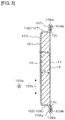
- FIG. 3 is a cross-sectional view of the metal roofing member 1 taken along the line III-III in FIG. 1
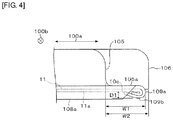
- FIG. 4 is a side view of the metal roofing member 1 when viewing the region IV of FIG. 1 along a depth direction 100b.
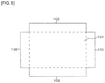
- FIG. 5 is an explanatory view showing another instance of a body portion 100 of FIG. 1
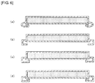
- FIG. 6 is an explanatory view showing another instance of a flange of FIG. 1 .
- the metal roofing member 1 as shown in FIGS. 1 to 4 is arranged together with other metal roofing members on a roof base of a building such as a house.
- the metal roofing member 1 is tightened to the roof base by driving tightening members such as, for example screws or nails into the roof base.
- the metal roofing member 1 is adapted such that its longitudinal direction (a width direction 100a of a body portion 100 described below) extends in a direction parallel to an eave of the roof and its short direction (a depth direction 100b of the body portion 100 described below) extends along an eave-ridge direction.
- the metal roofing member 1 includes a front substrate 10, a back substrate 11, and a core material 12.
- the front substrate 10 is made of a metal sheet and appears on the outer surface of the roof as the metal roofing material 1 is placed on the roof base.
- the metal sheet making up the front substrate 10 includes a hot-dip Zn-based plated steel sheet, a hot-dip Al plated steel sheet, a hot-dip Zn-based plated stainless steel sheet, a hot-dip Al plated stainless steel sheet, a stainless steel sheet, an Al sheet, a Ti sheet, a coated hot-dip Zn-based plated steel sheet, a coated hot-dip Al plated steel sheet, a coated hot-dip Zn-based plated stainless steel sheet, a coated hot-dip Al plated stainless steel sheet, a coated hot-dip Al plated stainless steel sheet, a coated hot-dip Al plated stainless steel sheet, a coated stainless steel sheet, a coated Al sheet or a coated Ti sheet.
- the thickness of the metal sheet is 0.27 mm or more and 0.5 mm or less.
- An increasing thickness of the metal sheet will result in increased strength, but increased weight.
- the thickness of the metal sheet of 0.27 mm or more can ensure strength required for the roofing member, and sufficiently provide wind pressure resistance performance and tread-down properties.
- the wind pressure resistance performance refers to performance for which the metal roofing member 1 can withstand strong wind without buckling of the metal roofing member 1.
- the thickness of the metal sheet of 0.5 mm or less can prevent the weight of the metal roofing member 1 from becoming excessive, thereby keeping down the total weight of the roof when equipment such as a solar cell module, a solar water heater, an outdoor unit of an air conditioner and snow melting equipment is provided on the roof.
- the front substrate 10 includes a box-shaped body portion 100 having a top plate 101 and peripheral wall portion 102.
- the body portion 100 is preferably formed by performing drawing or bulging processing on a metal sheet.
- each of the side wall portion 102 can have a wall surface that is continuous in the circumferential direction of the front substrate 10, and any likelihood that water enters the inside of the body portion 100 can be reduced.
- the steel sheet (the hot-dip Zn-based plated steel sheet, the hot-dip Al plated steel sheet, the hot-dip Zn-based plated stainless steel sheet, the hot-dip Al plated stainless steel sheet, the stainless steel sheet, the Al sheet, the Ti sheet, the coated hot-dip Zn-based plated steel sheet, the coated hot-dip Al plated steel sheet, the coated hot-dip Zn-based plated stainless steel sheet, the coated hot-dip Al plated stainless steel sheet or the coated stainless steel sheet) is used as the metal sheet of the front substrate 10 and when the body portion 100 is formed by the drawing or bulging processing, the hardness of the peripheral wall portion 102 are increased by work hardening.
- the Vickers hardness of the peripheral wall portion 102 can be increased to about 1.4 to 1.6 times the hardness before the working.
- the wind pressure resistance performance of the metal roofing member 1 is significantly improved by virtue of the fact that the peripheral wall portion 102 has the wall surface that is continuous in the circumferential direction of the front substrate 10, as described above, and by virtue of the fact that the hardness of the peripheral wall portion 102 is increased by work hardening.
- the core material 12 is made of, for example a foamed resin or the like, and is filled between the body portion 100 of the front substrate 10 and the back substrate 11.
- the filling of the core material 12 between the body portion 100 of the front substrate 10 and the back substrate 3 can lead to a stronger adhesion of the core material 12 to the inside of the body portion 100 as compared with an instance where a backing material such as a resin sheet or the like is attached onto the back side of the front substrate 11, so that the performance required for the roofing materials, such as rainfall noise reduction, heat insulation and tread-down properties, can be improved.
- the material of the core material 12 includes, but not limited to, for example, urethane, phenol and cyanurate resins.
- certified noncombustible materials must be used.
- the test for certification of noncombustible material is conducted by a heat release test according to the cone calorimeter test method defined in ISO 5660-1. If the foamed resin for forming the core material 12 is urethane having a higher calorific value or the like, the thickness of the core material 12 may be decreased, or inorganic expandable particles may be incorporated into the foamed resin.
- a height h of the body portion 100 filled with the core material 12 is preferably 4 mm or more and 8 mm or less.
- the height h of the body portion 100 of 4 mm or more enables sufficiently higher strength of the body portion 100, and improved wind pressure resistance.
- the height h of 4 mm or more can also provide improved heat insulation properties.
- the height h of the body portion 100 of 8 mm or less can prevent the organic mass of the core material 12 from becoming excessive, and can allow certification of noncombustible material to be more reliably obtained.
- the top plate 101 of the body portion 100 includes a plurality of tightening indicators 103 spaced apart from each other along the width direction 100a of the body portion 100.
- the tightening indicators 103 indicate positions for driving tightening members into the metal roofing member 1.
- Each of the tightening indicators 103 of this instance is composed of a concave portion having a circular shape in plane view.
- each of the tightening indicators 103 may adopt any other form in which the operator can visually or tactually recognize the tightening position of the tightening member, such as a convex portion, an opening, or a printed or engraved symbol.
- the peripheral wall portion 102 of the body portion 100 is provided with first side surfaces 105, second side surfaces 106, a ridge-side end surface 107, and an eave-side end surface 108.
- the first and second side surfaces 105, 106 are provided on both sides of the body portion 100 along the width direction 100a, respectively.
- the second side surface 106 is adapted to be positioned on the ridge side relative to the first side surface 105 when the metal roofing member 1 is placed on the roof base.
- the second side surface 106 is disposed so as to protrude to the outer side of the first side surface 105 along the width direction 100a of the body portion 100.
- a connection wall that extends along the width direction 100a is provided between the first and second side surfaces 105, 106.
- the connecting wall of this instance is formed by a slope that is inclined outward along the width direction 100a as the connecting wall approaches the second side surface 106 along the depth direction 100b.
- the connecting wall may be formed by a wall surface that is parallel to the width direction 100a or a curved surface that is directed outward along the width direction 100a as the connecting wall approaches the second side surface 106 along the depth direction 100b.
- the first side surface 105 is provided with a side flange 105a.
- the side flange 105a is comprised of a metal sheet extending from the lower end of the first side surface 105 toward the outer side along the width direction 100a, and is formed by folding back the metal sheet toward the back side of the front substrate 10 such that the metal sheet wraps around the back substrate 11.
- the providing of the side flange 105a integrally with the body portion 100 leads to improved durability (wind pressure resistance performance) of the metal roofing member 1 against an external force that will act to warp the metal roofing member 1 to the front side or the back side along a straight line along the width direction 100a.
- a protruding width W1 of the side flange 105a from the first side surface 105 is less than or equal to a protruding width W2 of the second side surface 106 from the first side surface 105 (W1 ⁇ W2). Further, the protruding width W1 of the side flange 105a from the first side surface 105 is preferably 2 mm or more and 5 mm or less. The protruding width W1 of 2 mm or more can provide the side flange 105a with sufficient strength and reliably prevent warping of the front substrate 10. The protruding width W1 of 5 mm or less can avoid decreased strength of the side flange 105a due to an increase in the protruding width W1 and maintain good design properties of the metal roofing member 1. In this instance, the total width of the metal roofing member 1 is about 908 mm, the protruding width W1 is about 4.5 mm, and the protruding width W2 is about 5.0 mm.
- the second side surface 106 is not provided with the flange, because a flange extending from the second side surface 106 is cut off after forming the box-shaped body portion 100.
- the ridge-side end surface 107 is positioned at one end along the depth direction 100b and is adapted to be located on the ridge side when the metal roofing member 1 is placed on the roof base.
- the ridge-side end surface 107 is provided with a straight portion 107a and inclined portions 107b.
- the straight portion 107a extends linearly along the width direction 100a.
- the inclined portions 107b are disposed on both sides of the straight portion 107a so as to connect the straight portion 107a and the second side surface 106.
- each of the inclined portions 107b extends obliquely with respect to the straight portion 107a so as to be directed toward the eave side (the other end side along the depth direction 100 b) as the inclined portion 107b approaches the second side surface 106.
- the straight portion 107a of the ridge-side end surface 107 is provided with a ride-side flange 107c.
- the ridge-side flange 107c is comprised of a metal sheet extending outward along the depth direction 100b from the lower end of the ridge-side end surface 107, and is formed by folding back the metal sheet toward the back side of the front substrate 10 such that the metal sheet wraps around the back substrate 11.
- a protruding width of the ridge-side flange 107c from the ridge-side end surface 107 is preferably 2 mm or more and 5 mm or less.
- each of the inclined portions 107b of the ridge-side end surface 170 is not provided with the flange, because the flange extending from each inclined portion 107 is cut off after forming the box-shaped body portion 100, as in the second side surface 106 as described above.
- each of the inclined portions 107b may be provided with a flange similar to the ridge-side flange 107c.
- the eave-side end surface 108 is located at the other end along the depth direction 100b and is adapted to be located on the eave side when the metal roofing member 1 is placed on the roof base.
- the eave-side end surface 108 is structured only by a straight portion extending along the width direction 100a.
- the eave-side end surface 108 may have any other shape.
- the eave-side flange 108 is comprised of a metal sheet extending outward along the depth direction 100b from the lower end of the eave-side end surface 108 and is formed by folding back the metal sheet toward the back side of the front substrate 10 such that the metal sheet wraps around the back substrate 11.
- a protruding width of the eave-side flange 108a from the eave-side end surface 108 is preferably 2 mm or more and 5 mm or less.
- the ridge-side flange 107c and the eave-side flange 108a extend along the width direction 100a and prevent warping of the metal roofing member 1 along the direction crossing the width direction 100a.
- each outer edge 10c of the metal sheet that makes up the front substrate 10 forms a tip of the flange.
- Each outer edge 10c is positioned on the inner side than a side end 109a of the flange.
- the outer edge 10c is often not coated or plated, the outer edge 10c can be prevented from being directly exposed to external corrosion factors, such as rainwater and sea salt particles, by virtue of the fact that the outer edge 10c is positioned on the inner side than the side end 109a.
- the folded-back portion of the flange is provided with a back end 109b that will be in contact with the roof base.
- a distance D1 (see FIG. 4 ) between the back end 109b and the back surface 11a of the back substrate 11 is 1 mm or more and 4 mm or less.
- the distance D1 between the back end 109b and the back surface 11a of 1 mm or more can prevent infiltration of water between the back end 109b and the back surface 11a due to the capillary phenomenon.
- the distance D1 between the back end 109b and the back surface 11a of 4 mm or less can avoid a decrease in the strength of the flange.
- the shape of the folded-back portion of the flange may be just one single folding through bending at 180° with constant curvature, as illustrated in FIGS. 3 and 4 , or may involve repeated folding after being folded-back, as illustrated in FIG. 6(a) .
- the folding-back of the flange 110 may be accomplished by bending at 90°, as illustrated in FIGS. 6(b)-(d) .
- the curvature radius at the bent portion of the metal sheet in the flange is preferably 0.5 mm or more.
- the curvature radius of 0.5 mm or more can prevent generation of cracks in the coated film and the plated layer of the metal sheet due to bending, and thus prevent peeling of the coated film and the plated layer and corrosion of the metal sheet.
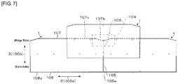
- FIG. 7 is an explanatory view showing a roofing structure and a roofing method using the metal roofing members 1 in FIGS. 1 to 4 .
- the roofing structure and the roofing method are described using the three metal roofing members 1, but it should be noted that actually more metal roofing members 1 are used for the roofing structure and the roofing method.
- a plurality of metal roofing members 1 are arranged on the roof base while abutting their sides against each other in a direction 2 parallel to the eave.
- each metal roofing member 1 is arranged on the roof base while abutting the second side surface 106 against the second side surface 106 of the other metal roofing member 1.
- the first side surfaces 105 of the respective metal roofing members 1 are spaced apart from each other, so that water permeated between the first side surfaces 105 will smoothly flow down to the eave side. Therefore, water pooled between the metal roofing members 1 can be reduced, thereby reducing any possibility of corrosion of the metal roofing members 1, as compared with an instance where a plurality of metal roofing members 1 are arranged while abutting the entire side surfaces against each other.
- the first side surface 105 is provided with the side flange 105a.
- the strength of the metal roofing member 1 is improved.
- the protruding width W1 of the side flange 105a is less than or equal to the protruding width W2 of the second side surface 106, in order to reliably abut the second side surfaces 106 of the respective metal roofing members 1 against each other.
- the protruding width W1 of the side flange 105a is equal to the protruding width W2 of the second side surface 106, the second side surfaces 106 as well as the side flanges 105a are abutted.
- Water may enter the ridge side of the metal roofing member 1 due to strong wind or the like.
- the ridge-side end surface 107 is provided with the inclined portions 107b, water entering the ridge side is guided by the inclined portion 107b to the abutted portion of the second side surfaces 106, and the water can be gradually discharged to the eave side through the butted portion.
- a plurality of metal roofing members 1 are arranged on the roof base while the metal roofing member 1 on the ridge side is superposed on the metal roofing member 1 on the eave side, in the eave-ridge direction 3.
- the metal roofing member 1 on the ridge side is overlapped with the metal roofing member 1 on the eave side such that the eave-side end portion (the side end 109a of the eave-side flange 108a) of the metal roofing member 1 on the ridge side is positioned above the first side surface 105 and the side flange 105a of the eave-side metal roofing member 1.
- an external force such as strong wind will act to warp the metal roofing member 1 on the eave side, starting at the eave-side end portion of the metal roofing material 1 on the ridge side.
- the external force can be withstood by the side flange 105a having relatively higher strength, so that the warping of the metal roofing member 1 on the eave side can be suppressed. That is, the wind pressure resistance performance is improved by the arrangement of the metal roofing members 1 as described above.
- the metal roofing member 1 on the ridge side is overlapped with the metal roofing member 1 on the eave side such that the second side surface 106 of the metal roofing member on the ridge side is placed above the ridge-side end portion (the side edge 109a of the ridge-side flange 107c) of the metal roofing substrate 1 on the eave side.
- the overlap of the metal roofing members 1 in such a way reduces any risk of water entering the ridge side of the metal roofing member 1 on the eave side through the gap between the metal roofing members 1 on the ridge side.
- Glass fiber paper having a size of 0.2 mm, Al metallized paper having a size of 0.2 mm, a PE resin film having a size of 0.2 mm, an Al foil having a size of 0.1 mm or a coated hot-dip Zn-based plated steel sheet having a size of 0.27 mm was used as the back substrate 11.
- a two-liquid mixture type foam resin was used as the core material 12.
- the mixing ratio of a polyol component and isocyanate, phenol or cyanurate component was 1:1, in ratio by weight.
- the front substrate 10 was processed to have a predetermined thickness and shape of the roofing member.
- the back substrate 11 was then disposed on the back side of the front substrate 10 so as to cover the opening of the body portion 100, and the foam resin was injected into the gap between the body portion 100 of the front substrate 10 and the back substrate 11, using a commercially available high-pressure injection machine. Foaming of the resin was accomplished by maintaining the resin for 2 minutes in a mold at which the temperature was adjusted to 70°C by circulating hot water; subsequently, the roofing member was removed from the mold, and was allowed to stand for 5 minutes at room temperature of 20°C, to complete foaming of the resin.
- the metal sheet extending from a lower edge of the body portion 100 toward the outer direction of the body portion 100 was cut such that the protruding width of the flange (the side flange 105a, the ridge-side flange 107c and the eave-side flange 108a) was 5 mm, and the cut metal sheet was subjected to a bending process by means of a bender to have a predetermined shape.
- the dimensions of the final metal roofing member 1 were 414 mm ⁇ 910 mm.
- the thickness of the final roofing member was in the range of from 3 mm to 8 mm.
- a specimen of a metal roofing member (conventional structure) was produced by subjecting a 0.3 mm coated hot-dip Zn-55% Al alloy plated steel sheet as the front substrate to inward 90°-bending of the four sides of the steel sheet to have a box shape using a bender, and injecting the foam resin in accordance with the method as described above.
- Glass fiber paper having a size of 0.2 mm was used as the back substrate of this metal roofing member.
- the thickness of the roofing member was 6 mm, while other conditions were the same as those described above.
- metal roofing members were also tested: a metal roofing member with no foam resin injected; a roofing member obtained by bonding a commercially available 0.3 mm thermally-insulating polyethylene sheet to a processed front substrate using an adhesive; a concrete roofing tile having a thickness of 6 mm; a clay roof tile having a thickness of 16 mm; and a metal roofing member of mating type that utilized a coated hot-dip Zn-55% Al alloy plated steel sheet (without backing material) having a thickness of 0.35 mm.
- the unit weight of each roofing member was measured and evaluated in accordance with the following criteria. It should be noted that the evaluation was made based on an assumption that a standard 130 N/m 2 solar cell module was placed on the roof, using the following evaluation criteria based on the total weight of the entire roof including the roofing member.
- O unit weight of roofing member of less than 250 N/m 2
- ⁇ unit weight of roofing member of 250 N/m 2 or more.
- the roofing member was placed on a pair of rod-like members disposed spaced apart from each other by 450 mm, such that the extension direction of the rod-like members was the short direction of the roofing member, and a maximum load was measured using an Autograph, in which case the positions of the rod-like members acted as supporting points and the intermediate position between the rod-like members acted as a force point.
- the bending strength of the roofing member was evaluated in accordance with the following criteria. O: maximum load of 160 N or more; ⁇ : maximum load of less than 160 Nmm and 50 N or more; and ⁇ : maximum load of less than 50 N.
- a commercially available waterproof sheet was affixed to a surface of a roofing board (a thickness of 12 mm), and four tiers of roofing members were roofed at an inclination angle of 30° by the overlap roofing illustrated in FIG. 7 to produce a simulated roof.
- the entire simulated roof was sprayed with tap water for 10 minutes to sufficiently wet the entire roof.
- the simulated roof was then dried by placing the simulated roof for 5 hours in a constant-temperature room at room temperature of 20°C.
- the gap between the roofing members (vertical connecting portion) in the ridge-eave direction was visually observed to evaluate the dry state.
- the roofing members were then stripped, and the dry state of the back substrate side of the roofing member and the waterproof sheet surface was visually observed and evaluated.
- the dry state was evaluated in accordance with the following criteria:
- Corrosion resistance was evaluated in accordance with the following criteria:
- Thermocouples were attached to the surface of the front substrate and the back surface of the roofing board of the simulated roof in which rainwater pooling had been evaluated. Twelve lamps (100/110 V, 150 W) were equidistantly arranged at positions of 180 mm from the surface of the simulated roof. The temperature of the back side of the roofing board after 1 hour of irradiation at a lamp output of 60% was measured by the thermocouples, to evaluate heat insulation properties.
- a simulated roof was produced in the same method as that of the above item (3).
- water responsive paper 104 available from Syngenta (Switzerland) was inserted between the roofing material on the eave side and the waterproof sheet, as shown in FIG. 7 .
- the water responsive paper 104 presents yellow color in an initial dry state, and as the water responsive paper 104 is contacted with water, the color of the contacted part is instantly changed to navy blue color.
- the entering of rainwater was evaluated according to the following criteria. For the degree of rainwater entering, water was sprayed for 7 minutes under an environment of a wind speed of 30 m/s on the simulated roof to simulate the situation where the roof was exposed to storm.
- the amount of rainwater at this time was 4,000 mL/min per 1 m 2 .
- O substantially no color change of the water responsive paper observed and substantially no entering of rainwater observed
- ⁇ slight color change of the water responsive paper observed and slight entering of rainwater observed
- ⁇ remarkable color change of the water responsive paper observed and remarkable entering of rainwater observed.
- the protruding width W1 of the flange was less than 2 mm, so that the bending strength was insufficient. In No. 11 the protruding width W1 was more than 5 mm, so that the bending strength was decreased.
- the protruding width W1 of the side flange 105a was more than or equal to the protruding width W2 of the second side surface 106, so that the second side surfaces were not abutted against each other and the gap was thus formed, and as result, rainwater entered the ridge direction from the opening of the abutted portion of the first side surfaces.
- the thickness of the front substrate was less than 0.27 mm, so that the bending strength was insufficient.
- the thickness of the front substrate was more than 0.5 mm, so that the evaluation of the roofing member weight was poor ( ⁇ ).
- the front substrate 10 was made of the coated hot-dip Al plated steel sheet, so that cracks were generated in the coated film and the plated layer, and as a result, corrosion was generated at the abutted portion between the roofing members and the evaluation rating of corrosion resistance was poor.
- the thickness of the body portion 100 was less than 4 mm, so that the evaluation of the bending strength was poor ( ⁇ ).
- the heat insulating performance was slightly lowered and evaluated as ( ⁇ ).
- the back substrate 11 was the coated hot-dip Zn-based plated steel sheet which was not lightweight, so that the evaluation of roofing member weight was poor.
- a lightweight material such as aluminum foil, aluminum metallized paper, aluminum hydroxide paper, calcium carbonate paper, a resin film or glass fiber paper as the back substrate 11.
- the authors carried out a wind pressure resistance test on the roofing members in accordance with Japanese Industrial Standard A 1515. That is, the presence or absence of breakage in a test member when pressed in a pressing process was evaluated using a dynamic wind pressure tester.
- a coated hot-dip Zn-55% Al plated steel sheet having a thickness of 0.27 mm and an aluminum sheet having a thickness of 0.5 mm were used as the material of the front substrate 10. These materials were subjected to bulging processing to produce the body portion 100. Glass fiber paper as the back substrate 11 was disposed on the back side of the front substrate 10 so as to cover the opening of the body portion 100, and a cyanurate resin was injected into the gap between the front substrate 10 and the back substrate 11, using a commercially available injection machine.
- Wind pressure resistance was evaluated on the basis of a breaking pressure at the time of induced breakage.
- the breaking pressure was a negative pressure of 6,000 N/m 2 or more
- the breaking pressure was a negative pressure of 5,000 N/m 2 or more and less than 6,000 N/m 2 . That is, it was found that improved wind pressure resistance can be achieved even if an aluminum sheet is used, and that further improved wind pressure resistance can also be achieved when a steel sheet is used.
- Work hardening of the peripheral wall portion 102 derived from bulging is more notably presented in the steel sheet than in the aluminum sheet; it is believed that this difference in hardness of the peripheral wall portion 102 brings about the difference in evaluation results in the wind pressure resistance test.
- the metal roofing member 1 is configured to be arranged on the roof base while abutting the second side surface 106 of the metal roofing member 1 against a second side surface 106 of other metal roofing member 1. Therefore, this can allow reduction of water pooled between the metal roofing members, and also allow reduction of water entering the ridge side of the metal roofing member 1. Further, since the first side surface 105 is provided with the side flange 105a, the strength of the metal roofing member 1 can be improved.
- the straight portion 107a of the ridge-side end surface 107 is provided with the ridge-side flange 107c, warping of the metal roofing member 1 along the direction crossing the width direction 100a can be reduced.
- the surface rigidity can be increased by providing the flanges 107a, 108b and 105a which surround the four sides of the roofing member.
- a force applied to the lower roof pressed by the tightened upper roofing member is increased, neither the upper roof nor the lower roof is easily deformed.
- the durability is improved.
- the flanges 107a, 108b and 105a which surround the four sides of the roof member have effects of improving the flatness of the roofing member itself and of suppressing initial warping and twist, and the gaps between the upper and lower roofing members generated due to the warping and twist.
- the body portion 100 includes the peripheral wall portion 102 comprised of a wall surface that is continuous in the circumferential direction of the front substrate 10, any the possibility of water entering the body portion 100 can be reduced.
- the protruding width W1 of the flange (the side flange 105a, the ridge-side flange 107c and the eave-side flange 108a) is 2 mm or more and 5 mm or less, and hence the flange can be imparted with sufficient strength, and the design properties of the metal roofing member 1 can be maintained satisfactorily.
- the metal sheet making up the front substrate 10 has a thickness of 0.27 mm or more and 0.5 mm or less, the strength required for the roofing member can be sufficiently ensured, and the weight of the metal roofing member 1 can be prevented from becoming excessively large.
- equipment such as a solar cell module, a solar water heater, an air conditioner outdoor unit or snow melting equipment is provided on the roof.
- the bent portion of the metal sheet included in the flange has a curvature radius of 0.5 mm or more. Therefore, it is possible to avoid the generation of cracks in the coated film and the plated layer of the metal sheet due to bending, so that corrosion of the metal sheet can be more reliably avoided.
- the body portion 100 has a height h of 4 mm or more and 8 mm or less, the certification of noncombustible material can be more surely obtained while maintaining the heat insulating properties and strength.
- the second side surface 106 of the metal roofing member 1 on the ridge side is positioned above the ridge-side end portion of the metal roofing member 1 on the eave side. Therefore, it is possible to reduce any risk that water enters the ridge side of the metal roofing member 1 on the eave side through the gap between the metal roofing members 1 on the ridge side.
Landscapes
- Engineering & Computer Science (AREA)
- Architecture (AREA)
- Civil Engineering (AREA)
- Structural Engineering (AREA)
- Mechanical Engineering (AREA)
- Roof Covering Using Slabs Or Stiff Sheets (AREA)
Claims (18)
- Élément de couverture métallique (1) destiné à être placé sur une base de toit avec d'autres éléments de couverture métallique, l'élément de couverture métallique (1) comprenant :un substrat avant (10) composé d'une tôle métallique, le substrat avant (10) comprenant une partie de corps (100) formée comme une boîte ;un substrat arrière (11) disposé sur un côté arrière du substrat avant (10), le substrat arrière (11) étant configuré pour recouvrir une cavité de la partie de corps (100) ; etun matériau central (12) qui remplit la cavité entre la partie de corps (100) et le substrat arrière (11) ;dans lequel la partie de corps (100) comprend : des premières surfaces latérales (105) ; et des secondes surfaces latérales (106), chacune des secondes surfaces latérales (106) étant adaptée pour être située côté faîtage de chacune des premières surfaces latérales (105) lorsque l'élément de couverture métallique (1) est placé sur la base de toit, chacune des secondes surfaces latérales (106) étant placée à un emplacement décalé vers le côté externe dans une direction de largeur (100a) de la partie de corps (100) par rapport à la première surface latérale (105) ;dans lequel chacune des premières surfaces latérales (105) comprend une bride latérale (105a) qui s'étend de l'extrémité inférieure de la première surface latérale correspondante (105) vers le côté externe dans la direction de largeur (100a), la bride latérale (105a) comprenant un pli de la tôle métallique orienté vers le côté arrière du substrat avant (10) de sorte que ledit pli s'enroule autour du substrat arrière (11), ledit pli s'étendant de l'extrémité inférieure de la première surface latérale (105) vers le côté externe dans la direction de largeur (100a) ;dans lequel la bride latérale (105a) comprend une extrémité arrière (109b) adaptée pour être en contact avec la base de toit ;dans lequel une distance (D1) entre l'extrémité arrière (109b) de la bride latérale (105a) et la surface arrière (11a) du substrat arrière (11) est de 1 mm ou plus et de 4 mm ou moins ;dans lequel une largeur de saillie (W1) de la bride latérale (105a) depuis la première surface latérale (105) est égale ou inférieure à une largeur de saillie (W2) de la seconde surface latérale (106) depuis la première surface latérale (105) du même côté de la partie de corps (100) dans la direction de largeur (100a) ; etdans lequel l'élément de couverture métallique (1) est configuré pour être placé sur la base de toit tout en faisant buter au moins la seconde surface latérale (106) contre une seconde surface latérale (106) d'un élément de couverture métallique adjacent.
- Élément de couverture métallique (1) selon la revendication 1,
dans lequel la partie de corps (100) comprend une surface d'extrémité côté faîtage (107) située sur le côté faîtage lorsque l'élément de couverture métallique (1) est placé sur la base de toit ;
et
dans lequel la surface d'extrémité côté faîtage (107) comprend une partie droite (107a) qui s'étend dans la direction de largeur (100a) ; et des parties inclinées (107b) prévues des deux côtés de la partie droite (107a), chacune des parties inclinées (107b) reliant la partie droite (107a) et la seconde surface latérale (106), et s'étendant de façon à être inclinée par rapport à la partie droite (107a) de sorte que chaque partie inclinée (107b) soit orientée vers le côté corniche lorsqu'elle s'approche de la seconde surface latérale (106). - Élément de couverture métallique (1) selon la revendication 2,
dans lequel la partie droite (107a) de la surface d'extrémité côté faîtage (107) comprend une bride côté faîtage (107c) qui s'étend vers l'extérieur dans une direction de profondeur (100b) de la partie de corps (100) depuis l'extrémité inférieure de la surface d'extrémité côté faîtage (107), la bride côté faîtage (107c) comprenant un pli de la tôle métallique orienté vers le côté arrière du substrat avant (10) de sorte que ledit pli s'enroule autour du substrat arrière (11), la tôle métallique s'étendant de l'extrémité inférieure de la surface d'extrémité côté faîtage (107) vers le côté externe dans la direction de largeur (100a) de la partie de corps (100) ;
dans lequel la bride côté faîtage (107c) comprend une extrémité arrière (109b) qui sera en contact avec la base de toit ; et
dans lequel une distance (D1) entre l'extrémité arrière (109b) de la bride côté faîtage (107c) et la surface arrière (11a) du substrat arrière (11) est de 1 mm ou plus et de 4 mm ou moins. - Élément de couverture métallique (1) selon l'une quelconque des revendications 1 à 3,
dans lequel la partie de corps (100) comprend une surface d'extrémité côté corniche (108) située sur le côté corniche lorsque l'élément de couverture métallique (1) est placé sur la base de toit ;
et
dans lequel la surface d'extrémité côté corniche (108) comprend une bride côté corniche (108a) qui s'étend vers l'extérieur dans une direction de profondeur (100b) de la partie de corps (100) depuis l'extrémité inférieure de la surface d'extrémité côté corniche (108), la bride côté corniche (108a) comprenant un pli de la tôle métallique orienté vers le côté arrière du substrat avant (10) de sorte que ledit pli s'enroule autour du substrat arrière (11), la tôle métallique s'étendant de l'extrémité inférieure de la surface d'extrémité côté corniche (108) vers le côté externe dans la direction de largeur (100a) de la partie de corps (100) ;
dans lequel la bride côté corniche (108) comprend une extrémité arrière (109a) qui sera en contact avec la base de toit ; et
dans lequel une distance (D1) entre l'extrémité arrière (109a) de la bride côté corniche (108a) et la surface arrière (11a) du substrat arrière (11) est de 1 mm ou plus et de 4 mm ou moins. - Élément de couverture métallique (1) selon l'une quelconque des revendications 1 à 4, dans lequel la partie de corps (100) comprend une partie de paroi périphérique (102) composée d'une surface de paroi qui est continue dans la direction circonférentielle du substrat avant (10).
- Élément de couverture métallique (1) selon l'une quelconque des revendications 1 à 5, dans lequel la largeur de saillie (W1) de la bride latérale (105a) depuis la première surface latérale (105) est de 2 mm ou plus et de 5 mm ou moins.
- Élément de couverture métallique (1) selon l'une quelconque des revendications 1 à 6, dans lequel la tôle métallique, qui est un matériau du substrat avant, comprend une tôle d'acier zingué à base de zinc galvanisée à chaud, une tôle d'acier zingué à base d'aluminium galvanisée à chaud, une tôle d'acier inoxydable zingué à base de zinc galvanisée à chaud, une tôle d'acier inoxydable zingué à base d'aluminium galvanisée à chaud, une tôle d'acier inoxydable, une tôle d'aluminium, une tôle de titane, une tôle d'acier zingué à base de zinc galvanisée à chaud et enrobée, une tôle d'acier zingué à base d'aluminium galvanisée à chaud et enrobée, une tôle d'acier inoxydable zingué à base de zinc galvanisée à chaud et enrobée, une tôle d'acier inoxydable zingué à base d'aluminium galvanisée à chaud et enrobée, une tôle d'acier inoxydable enrobée, une tôle d'aluminium enrobée, ou une tôle de titane enrobée.
- Élément de couverture métallique (1) selon la revendication 7, dans lequel la tôle métallique qui constitue le substrat avant (10) possède une épaisseur de 0,27 mm ou plus et de 0,5 mm ou moins.
- Élément de couverture métallique (1) selon la revendication 7 ou 8, dans lequel une partie cintrée de la tôle métallique incluse dans la bride latérale présente un rayon de courbure de 0,5 mm ou plus.
- Élément de couverture métallique (1) selon l'une quelconque des revendications 1 à 9, dans lequel la partie de corps (100) possède une hauteur (h) de 4 mm ou plus et de 8 mm ou moins.
- Élément de couverture métallique (1) selon l'une quelconque des revendications 1 à 10, dans lequel le substrat arrière (11) comprend une feuille d'aluminium, du papier d'aluminium métallisé, du papier d'hydroxyde d'aluminium, du papier de carbonate de calcium, un film de résine ou du papier en fibre de verre.
- Procédé de fabrication de l'élément de couverture métallique (1) selon la revendication 5,
dans lequel la tôle métallique, qui est un matériau du substrat avant (10), comprend une tôle d'acier zingué à base de zinc galvanisée à chaud, une tôle d'acier zingué à base d'aluminium galvanisée à chaud, une tôle d'acier inoxydable zingué à base de zinc galvanisée à chaud, une tôle d'acier inoxydable zingué à base d'aluminium galvanisée à chaud, une tôle d'acier inoxydable, une tôle d'aluminium, une tôle de titane, une tôle d'acier zingué à base de zinc galvanisée à chaud et enrobée, une tôle d'acier zingué à base d'aluminium galvanisée à chaud et enrobée, une tôle d'acier inoxydable zingué à base de zinc galvanisée à chaud et enrobée, une tôle d'acier inoxydable zingué à base d'aluminium galvanisée à chaud et enrobée, ou une tôle d'acier inoxydable enrobée ; et
dans lequel le procédé comprend le fait de soumettre la tôle métallique à un étirage ou un gonflement afin de former la partie de corps (100). - Structure de couverture comprenant une pluralité d'éléments de couverture métalliques (1) selon la revendication 1,
dans lequel les éléments de couverture métalliques (1) sont placés sur la base de toit tout en faisant buter au moins les secondes surfaces latérales (106) d'un élément de couverture métallique adjacent. - Structure de couverture selon la revendication 13, dans laquelle l'élément de couverture métallique (1) côté faîtage est placé par chevauchement avec l'élément de couverture métallique (1) côté corniche de sorte qu'une partie d'extrémité côté corniche de l'élément de couverture métallique (1) côté faîtage soit positionnée au-dessus de la première surface latérale (105) et de la bride latérale (105a) de l'élément de couverture métallique (1) côté corniche.
- Structure de couverture selon la revendication 14, dans laquelle la seconde surface latérale (106) de l'élément de couverture métallique (1) côté faîtage est positionnée au-dessus d'une partie d'extrémité côté faîtage de l'élément de couverture métallique (1) côté corniche.
- Procédé de couverture qui utilise une pluralité d'éléments de couverture métalliques (1) selon la revendication 1,
dans lequel le procédé comprend le placement de la pluralité d'éléments de couverture métalliques (1) sur la base du toit tout en faisant buter au moins les secondes surfaces latérales (106) les unes contre les autres. - Procédé de couverture selon la revendication 16, dans lequel le procédé comprend en outre le placement de l'élément de couverture métallique (1) côté faîtage par chevauchement avec l'élément de couverture métallique (1) côté corniche de sorte qu'une partie d'extrémité côté corniche de l'élément de couverture métallique (1) côté faîtage soit positionnée au-dessus de la première surface latérale (105) et de la bride latérale (105a) de l'élément de couverture métallique (1) côté corniche.
- Procédé de couverture selon la revendication 17, dans lequel, lors du placement de l'élément de couverture métallique (1) côté faîtage par chevauchement avec l'élément de couverture métallique (1) côté corniche, la seconde surface latérale (106) de l'élément de couverture métallique (1) côté faîtage est positionnée au-dessus d'une partie d'extrémité côté faîtage de l'élément de couverture métallique (1) côté corniche.
Applications Claiming Priority (2)
| Application Number | Priority Date | Filing Date | Title |
|---|---|---|---|
| JP2015231569A JP5999824B1 (ja) | 2015-11-27 | 2015-11-27 | 金属屋根材並びにそれを用いた屋根葺き構造及び屋根葺き方法 |
| PCT/JP2016/059384 WO2017090257A1 (fr) | 2015-11-27 | 2016-03-24 | Matériau de couverture métallique, et structure de couverture et procédé de couverture les mettant en œuvre |
Publications (3)
| Publication Number | Publication Date |
|---|---|
| EP3382121A1 EP3382121A1 (fr) | 2018-10-03 |
| EP3382121A4 EP3382121A4 (fr) | 2018-12-05 |
| EP3382121B1 true EP3382121B1 (fr) | 2020-04-22 |
Family
ID=56997672
Family Applications (1)
| Application Number | Title | Priority Date | Filing Date |
|---|---|---|---|
| EP16868208.6A Not-in-force EP3382121B1 (fr) | 2015-11-27 | 2016-03-24 | Élément de couverture métallique, structure de couverture, procédé de production d'un tel élément de couverture métallique et procédé de couverture |
Country Status (10)
| Country | Link |
|---|---|
| US (1) | US10597874B2 (fr) |
| EP (1) | EP3382121B1 (fr) |
| JP (1) | JP5999824B1 (fr) |
| KR (1) | KR101980061B1 (fr) |
| CN (1) | CN108474209B (fr) |
| AU (1) | AU2016360048B2 (fr) |
| EA (1) | EA036580B1 (fr) |
| MY (1) | MY172376A (fr) |
| TW (1) | TWI720069B (fr) |
| WO (1) | WO2017090257A1 (fr) |
Families Citing this family (5)
| Publication number | Priority date | Publication date | Assignee | Title |
|---|---|---|---|---|
| EA201992465A1 (ru) | 2017-05-23 | 2020-05-08 | Ниппон Стил Ниссин Ко., Лтд. | Металлический кровельный материал и способ выполнения кровли с применением упомянутого материала |
| JP6981147B2 (ja) * | 2017-09-28 | 2021-12-15 | 日本製鉄株式会社 | 金属壁材及びそれを用いた壁施工方法 |
| JP2019065622A (ja) * | 2017-10-03 | 2019-04-25 | 日新製鋼株式会社 | 金属屋根材の製造方法 |
| CA3083230A1 (fr) * | 2017-11-24 | 2019-05-31 | Bluescope Steel Limited | Panneau |
| CN111321849B (zh) * | 2018-12-14 | 2025-11-11 | 东君新能源有限公司 | 一种用于瓦片安装的固定装置及具有其的可拆卸瓦片 |
Family Cites Families (63)
| Publication number | Priority date | Publication date | Assignee | Title |
|---|---|---|---|---|
| US157392A (en) * | 1874-12-01 | Improvement in roofing-tiles | ||
| US460283A (en) * | 1891-09-29 | Metallic ceiling | ||
| US1519350A (en) * | 1922-05-27 | 1924-12-16 | George A Belding | Metal shingle |
| US2065478A (en) * | 1935-11-18 | 1936-12-22 | Schulman Joseph | Roof construction |
| US2882840A (en) * | 1956-02-01 | 1959-04-21 | George F Waske | Shingle construction |
| US2961804A (en) * | 1957-12-16 | 1960-11-29 | Globe Roofing Products Co Inc | Metallic surfaced siding and roofing material |
| US3312031A (en) * | 1966-04-04 | 1967-04-04 | Kaiser Aluminium Chem Corp | Shingle structure with reentrant joint configurations and a nailing tab |
| US3394515A (en) * | 1968-01-02 | 1968-07-30 | Elwin G Smith & Company Inc | Roofing and siding panel construction |
| US3667184A (en) * | 1970-02-24 | 1972-06-06 | Clifford C Merrill | Interlocking metal shingle construction |
| US3760546A (en) * | 1971-08-24 | 1973-09-25 | Holiday Recreation Prod Inc | Modular roof construction |
| CA1042177A (fr) * | 1976-05-06 | 1978-11-14 | Louis L. Vallee | Bardeau metallique de toiture |
| US4244353A (en) * | 1977-04-07 | 1981-01-13 | Straza George T | Solar heating shingle roof structure |
| CA1071826A (fr) * | 1977-12-14 | 1980-02-19 | Louis L. Vallee | Conception moderne de toits a bardeaux metalliques |
| US4445305A (en) * | 1982-09-27 | 1984-05-01 | Orie Sr Thomas A | Insulating secondary roof system |
| CN1005870B (zh) * | 1986-06-17 | 1989-11-22 | 松下电器产业株式会社 | 潜热蓄热装置 |
| FR2608964B1 (fr) * | 1986-12-24 | 1989-10-20 | Saint Gobain Isover | Panneaux composites moules |
| SE459761B (sv) * | 1987-12-07 | 1989-07-31 | Nordisk Plaatformning Ab | Beklaednadselement |
| JPH01158165A (ja) | 1987-12-15 | 1989-06-21 | Ig Tech Res Inc | 金属パネル |
| US5442888A (en) * | 1992-12-08 | 1995-08-22 | Ilnyckyj; Peter | Shingles |
| CN2152761Y (zh) * | 1993-03-10 | 1994-01-12 | 赖忠喜 | 金属浪板 |
| US5349801A (en) * | 1993-08-25 | 1994-09-27 | Aluminum Company Of America | Sheet metal shingle |
| US5469680A (en) * | 1994-03-18 | 1995-11-28 | Revere Copper Products, Inc. | Metal roofing system |
| WO1995026451A1 (fr) * | 1994-03-25 | 1995-10-05 | Plath Construction, Inc. | Bardeau metallique |
| US5495654A (en) * | 1994-04-08 | 1996-03-05 | Weirton Steel Corporation | Preparing sheet metal and fabricating roofing shingles |
| US5625999A (en) * | 1994-08-23 | 1997-05-06 | International Paper Company | Fiberglass sandwich panel |
| US5685117A (en) * | 1995-04-13 | 1997-11-11 | Nicholson; Joseph R. | Shingle system and fastening strip |
| US5784848A (en) * | 1996-11-05 | 1998-07-28 | Toscano; Philip | Roofing system and shingle |
| US5799460A (en) * | 1997-02-27 | 1998-09-01 | Brian Dary | Method of shingling a roof and interlocking roofing system |
| US5711127A (en) * | 1997-03-05 | 1998-01-27 | Sabourin; Brunelle P. | Roof shingle |
| US5842315A (en) * | 1997-03-24 | 1998-12-01 | Tung Yik Trading Co., Ltd. | Corrugated board structure |
| JPH10306548A (ja) * | 1997-05-09 | 1998-11-17 | Takehiko Kimura | 金属屋根板とその金属屋根板の係合方法 |
| US6173546B1 (en) * | 1998-08-28 | 2001-01-16 | James P Schafer | Interlocking metal shingle |
| JP3388208B2 (ja) * | 1999-09-21 | 2003-03-17 | 宗勉 城田 | 屋根葺材 |
| CA2331166A1 (fr) * | 2001-01-16 | 2002-07-16 | Pierre Tremblay | Bardeau de toiture metallique |
| JP2002309752A (ja) | 2001-04-18 | 2002-10-23 | Sekisui Chem Co Ltd | 壁パネルおよびその製造方法 |
| JP2003074147A (ja) | 2001-09-03 | 2003-03-12 | Sekisui Chem Co Ltd | 金属製屋根材 |
| JP2003074163A (ja) * | 2001-09-04 | 2003-03-12 | Munemasu Shirota | 外装材 |
| US6883290B2 (en) * | 2002-02-20 | 2005-04-26 | Powerlight Corporation | Shingle system and method |
| US6708463B2 (en) * | 2002-02-25 | 2004-03-23 | King T. Chai | Method and apparatus for repairing roof covering |
| US7178301B2 (en) * | 2002-10-25 | 2007-02-20 | Albright Gary T | Simulated wood roofing shake |
| KR200327057Y1 (ko) * | 2003-06-26 | 2003-09-19 | (주)로자 | 건축물 내외장용 거멀접기형 패널 |
| JP3709485B1 (ja) * | 2004-10-08 | 2005-10-26 | 株式会社昭和 | ライニング構造 |
| JP2006257783A (ja) * | 2005-03-18 | 2006-09-28 | Tiger Vacuum Bottle Co Ltd | 屋根瓦 |
| CA2610464A1 (fr) * | 2005-06-13 | 2006-12-21 | Kingspan Research And Developments Limited | Panneau de toit |
| US8191326B2 (en) * | 2005-06-24 | 2012-06-05 | American Metal Ceiling Panel Manufacturing, Inc. | Decorative room panel |
| ITMI20051199A1 (it) * | 2005-06-24 | 2006-12-25 | Intersider Acciai S P A | Piastrella per rivestimenti in metallo metodo per la produzione e rivestimenti relativi |
| CN200958265Y (zh) * | 2006-03-31 | 2007-10-10 | 桑永明 | 一种房屋用复合板 |
| US20100186334A1 (en) * | 2009-01-27 | 2010-07-29 | Seem Charles T | Metal roofing shingle, metal roofing shingle system, and method of installing |
| WO2011149706A1 (fr) * | 2010-05-27 | 2011-12-01 | Dow Global Technologies Llc | Procédé de fabrication d'un article en mousse façonné |
| NZ592562A (en) * | 2011-04-29 | 2013-11-29 | Edward Lawrence Noton | An Improved Roof Tile |
| CA2876992A1 (fr) * | 2011-08-16 | 2013-02-16 | Joseph Robert Nicholson | Element de toit |
| WO2013054571A1 (fr) * | 2011-10-13 | 2013-04-18 | 日鉄住金鋼板株式会社 | Panneau de construction, et structure pour monter un panneau de construction sur un matériau de base |
| JP5898461B2 (ja) * | 2011-11-02 | 2016-04-06 | 日鉄住金鋼板株式会社 | 屋根材 |
| US8898963B1 (en) * | 2011-11-03 | 2014-12-02 | Certainteed Corporation | Roofing shingles with reduced usage of conventional shingle material and having a combination vertical and lateral lap extension |
| EP2749707B1 (fr) * | 2012-12-27 | 2017-06-14 | VKR Holding A/S | Élément de jupe utilisé dans un solin pour structure pénétrant dans le toit et utilisation d'un tel élément dans un solin sur une fenêtre de toit montée sur un toit incliné |
| US9598857B2 (en) * | 2013-01-14 | 2017-03-21 | Nanopore, Inc. | Thermal insulation products for insulating buildings and other enclosed environments |
| JP5785242B2 (ja) * | 2013-09-30 | 2015-09-24 | 日鉄住金鋼板株式会社 | 屋根材及び屋根構造 |
| CN204112610U (zh) * | 2014-01-26 | 2015-01-21 | 广东华途仕建材实业有限公司 | 一种新型的金属屋面板 |
| US9322173B2 (en) * | 2014-02-05 | 2016-04-26 | Michael Pisani | Lightweight shingle assembly |
| JP6362563B2 (ja) * | 2015-03-27 | 2018-07-25 | 日新製鋼株式会社 | 金属屋根材及びその製造方法並びに屋根葺き構造及び屋根葺き方法 |
| JP5864015B1 (ja) * | 2015-03-27 | 2016-02-17 | 日新製鋼株式会社 | 金属屋根材、それを用いた屋根葺き構造及び屋根葺き方法並びに金属屋根材製造方法 |
| JP6110973B1 (ja) * | 2015-10-02 | 2017-04-05 | 日新製鋼株式会社 | 金属屋根材及び屋根葺き方法 |
| MY188170A (en) * | 2015-10-02 | 2021-11-24 | Nisshin Steel Co Ltd | Metal roofing material and roofing method |
-
2015
- 2015-11-27 JP JP2015231569A patent/JP5999824B1/ja not_active Expired - Fee Related
-
2016
- 2016-03-24 CN CN201680069135.0A patent/CN108474209B/zh not_active Expired - Fee Related
- 2016-03-24 EP EP16868208.6A patent/EP3382121B1/fr not_active Not-in-force
- 2016-03-24 EA EA201890871A patent/EA036580B1/ru not_active IP Right Cessation
- 2016-03-24 WO PCT/JP2016/059384 patent/WO2017090257A1/fr not_active Ceased
- 2016-03-24 KR KR1020187018242A patent/KR101980061B1/ko not_active Expired - Fee Related
- 2016-03-24 MY MYPI2018701625A patent/MY172376A/en unknown
- 2016-03-24 AU AU2016360048A patent/AU2016360048B2/en not_active Ceased
- 2016-03-24 US US15/778,100 patent/US10597874B2/en active Active
- 2016-11-25 TW TW105138852A patent/TWI720069B/zh not_active IP Right Cessation
Non-Patent Citations (1)
| Title |
|---|
| None * |
Also Published As
| Publication number | Publication date |
|---|---|
| JP5999824B1 (ja) | 2016-09-28 |
| CN108474209A (zh) | 2018-08-31 |
| EP3382121A1 (fr) | 2018-10-03 |
| AU2016360048A1 (en) | 2018-05-17 |
| KR101980061B1 (ko) | 2019-05-17 |
| EA201890871A1 (ru) | 2018-09-28 |
| CN108474209B (zh) | 2019-10-29 |
| US20190264448A1 (en) | 2019-08-29 |
| WO2017090257A1 (fr) | 2017-06-01 |
| EA036580B1 (ru) | 2020-11-25 |
| AU2016360048B2 (en) | 2019-06-27 |
| TWI720069B (zh) | 2021-03-01 |
| TW201723284A (zh) | 2017-07-01 |
| US10597874B2 (en) | 2020-03-24 |
| MY172376A (en) | 2019-11-21 |
| KR20180079456A (ko) | 2018-07-10 |
| EP3382121A4 (fr) | 2018-12-05 |
| JP2017096048A (ja) | 2017-06-01 |
Similar Documents
| Publication | Publication Date | Title |
|---|---|---|
| US10233645B2 (en) | Metal roofing member, and roofing structure and roofing method using same | |
| EP3382121B1 (fr) | Élément de couverture métallique, structure de couverture, procédé de production d'un tel élément de couverture métallique et procédé de couverture | |
| JP6479922B1 (ja) | 屋根の補修方法及びその屋根構造 | |
| CN102182280B (zh) | 一种山墙边滑动屋面板刚性防水系统 | |
| KR102107952B1 (ko) | 금속 지붕재 | |
| US10400455B2 (en) | Metal roofing member, production method thereof, roofing structure and roofing method | |
| CN202031258U (zh) | 一种屋面滑动支架 | |
| JP6545328B2 (ja) | 金属屋根材及びその製造方法並びに屋根葺き構造及び屋根葺き方法 | |
| JP2017179862A (ja) | 金属屋根材及びそれを用いた屋根葺き方法 | |
| CN206279553U (zh) | 新型地下建筑 | |
| EP2360324A1 (fr) | Panneau isolé pour toiture et procédé de couvrage | |
| WO2019069679A1 (fr) | Procédé de fabrication de matériau de toiture métallique | |
| JP2018127854A (ja) | 横葺き屋根の施工方法、及び横葺き屋根 | |
| TW201900995A (zh) | 金屬屋頂構材及使用該金屬屋頂構材之屋頂敷設方法 |
Legal Events
| Date | Code | Title | Description |
|---|---|---|---|
| STAA | Information on the status of an ep patent application or granted ep patent |
Free format text: STATUS: THE INTERNATIONAL PUBLICATION HAS BEEN MADE |
|
| PUAI | Public reference made under article 153(3) epc to a published international application that has entered the european phase |
Free format text: ORIGINAL CODE: 0009012 |
|
| STAA | Information on the status of an ep patent application or granted ep patent |
Free format text: STATUS: REQUEST FOR EXAMINATION WAS MADE |
|
| 17P | Request for examination filed |
Effective date: 20180518 |
|
| AK | Designated contracting states |
Kind code of ref document: A1 Designated state(s): AL AT BE BG CH CY CZ DE DK EE ES FI FR GB GR HR HU IE IS IT LI LT LU LV MC MK MT NL NO PL PT RO RS SE SI SK SM TR |
|
| AX | Request for extension of the european patent |
Extension state: BA ME |
|
| A4 | Supplementary search report drawn up and despatched |
Effective date: 20181106 |
|
| RIC1 | Information provided on ipc code assigned before grant |
Ipc: E04D 1/24 20060101ALI20181030BHEP Ipc: E04D 1/28 20060101ALI20181030BHEP Ipc: E04D 1/18 20060101AFI20181030BHEP Ipc: E04D 1/34 20060101ALI20181030BHEP Ipc: E04D 3/35 20060101ALI20181030BHEP |
|
| DAV | Request for validation of the european patent (deleted) | ||
| DAX | Request for extension of the european patent (deleted) | ||
| STAA | Information on the status of an ep patent application or granted ep patent |
Free format text: STATUS: EXAMINATION IS IN PROGRESS |
|
| 17Q | First examination report despatched |
Effective date: 20190628 |
|
| GRAP | Despatch of communication of intention to grant a patent |
Free format text: ORIGINAL CODE: EPIDOSNIGR1 |
|
| STAA | Information on the status of an ep patent application or granted ep patent |
Free format text: STATUS: GRANT OF PATENT IS INTENDED |
|
| INTG | Intention to grant announced |
Effective date: 20191104 |
|
| GRAS | Grant fee paid |
Free format text: ORIGINAL CODE: EPIDOSNIGR3 |
|
| RAP1 | Party data changed (applicant data changed or rights of an application transferred) |
Owner name: NIPPON STEEL NISSHIN CO., LTD. |
|
| GRAA | (expected) grant |
Free format text: ORIGINAL CODE: 0009210 |
|
| STAA | Information on the status of an ep patent application or granted ep patent |
Free format text: STATUS: THE PATENT HAS BEEN GRANTED |
|
| AK | Designated contracting states |
Kind code of ref document: B1 Designated state(s): AL AT BE BG CH CY CZ DE DK EE ES FI FR GB GR HR HU IE IS IT LI LT LU LV MC MK MT NL NO PL PT RO RS SE SI SK SM TR |
|
| REG | Reference to a national code |
Ref country code: CH Ref legal event code: EP |
|
| REG | Reference to a national code |
Ref country code: IE Ref legal event code: FG4D |
|
| REG | Reference to a national code |
Ref country code: DE Ref legal event code: R096 Ref document number: 602016034795 Country of ref document: DE |
|
| REG | Reference to a national code |
Ref country code: AT Ref legal event code: REF Ref document number: 1260242 Country of ref document: AT Kind code of ref document: T Effective date: 20200515 |
|
| REG | Reference to a national code |
Ref country code: LT Ref legal event code: MG4D |
|
| REG | Reference to a national code |
Ref country code: NL Ref legal event code: MP Effective date: 20200422 |
|
| PG25 | Lapsed in a contracting state [announced via postgrant information from national office to epo] |
Ref country code: FI Free format text: LAPSE BECAUSE OF FAILURE TO SUBMIT A TRANSLATION OF THE DESCRIPTION OR TO PAY THE FEE WITHIN THE PRESCRIBED TIME-LIMIT Effective date: 20200422 Ref country code: NO Free format text: LAPSE BECAUSE OF FAILURE TO SUBMIT A TRANSLATION OF THE DESCRIPTION OR TO PAY THE FEE WITHIN THE PRESCRIBED TIME-LIMIT Effective date: 20200722 Ref country code: LT Free format text: LAPSE BECAUSE OF FAILURE TO SUBMIT A TRANSLATION OF THE DESCRIPTION OR TO PAY THE FEE WITHIN THE PRESCRIBED TIME-LIMIT Effective date: 20200422 Ref country code: NL Free format text: LAPSE BECAUSE OF FAILURE TO SUBMIT A TRANSLATION OF THE DESCRIPTION OR TO PAY THE FEE WITHIN THE PRESCRIBED TIME-LIMIT Effective date: 20200422 Ref country code: PT Free format text: LAPSE BECAUSE OF FAILURE TO SUBMIT A TRANSLATION OF THE DESCRIPTION OR TO PAY THE FEE WITHIN THE PRESCRIBED TIME-LIMIT Effective date: 20200824 Ref country code: IS Free format text: LAPSE BECAUSE OF FAILURE TO SUBMIT A TRANSLATION OF THE DESCRIPTION OR TO PAY THE FEE WITHIN THE PRESCRIBED TIME-LIMIT Effective date: 20200822 Ref country code: SE Free format text: LAPSE BECAUSE OF FAILURE TO SUBMIT A TRANSLATION OF THE DESCRIPTION OR TO PAY THE FEE WITHIN THE PRESCRIBED TIME-LIMIT Effective date: 20200422 Ref country code: GR Free format text: LAPSE BECAUSE OF FAILURE TO SUBMIT A TRANSLATION OF THE DESCRIPTION OR TO PAY THE FEE WITHIN THE PRESCRIBED TIME-LIMIT Effective date: 20200723 |
|
| REG | Reference to a national code |
Ref country code: AT Ref legal event code: MK05 Ref document number: 1260242 Country of ref document: AT Kind code of ref document: T Effective date: 20200422 |
|
| PG25 | Lapsed in a contracting state [announced via postgrant information from national office to epo] |
Ref country code: BG Free format text: LAPSE BECAUSE OF FAILURE TO SUBMIT A TRANSLATION OF THE DESCRIPTION OR TO PAY THE FEE WITHIN THE PRESCRIBED TIME-LIMIT Effective date: 20200722 Ref country code: RS Free format text: LAPSE BECAUSE OF FAILURE TO SUBMIT A TRANSLATION OF THE DESCRIPTION OR TO PAY THE FEE WITHIN THE PRESCRIBED TIME-LIMIT Effective date: 20200422 Ref country code: LV Free format text: LAPSE BECAUSE OF FAILURE TO SUBMIT A TRANSLATION OF THE DESCRIPTION OR TO PAY THE FEE WITHIN THE PRESCRIBED TIME-LIMIT Effective date: 20200422 Ref country code: HR Free format text: LAPSE BECAUSE OF FAILURE TO SUBMIT A TRANSLATION OF THE DESCRIPTION OR TO PAY THE FEE WITHIN THE PRESCRIBED TIME-LIMIT Effective date: 20200422 |
|
| PG25 | Lapsed in a contracting state [announced via postgrant information from national office to epo] |
Ref country code: AL Free format text: LAPSE BECAUSE OF FAILURE TO SUBMIT A TRANSLATION OF THE DESCRIPTION OR TO PAY THE FEE WITHIN THE PRESCRIBED TIME-LIMIT Effective date: 20200422 |
|
| REG | Reference to a national code |
Ref country code: DE Ref legal event code: R097 Ref document number: 602016034795 Country of ref document: DE |
|
| PG25 | Lapsed in a contracting state [announced via postgrant information from national office to epo] |
Ref country code: ES Free format text: LAPSE BECAUSE OF FAILURE TO SUBMIT A TRANSLATION OF THE DESCRIPTION OR TO PAY THE FEE WITHIN THE PRESCRIBED TIME-LIMIT Effective date: 20200422 Ref country code: DK Free format text: LAPSE BECAUSE OF FAILURE TO SUBMIT A TRANSLATION OF THE DESCRIPTION OR TO PAY THE FEE WITHIN THE PRESCRIBED TIME-LIMIT Effective date: 20200422 Ref country code: CZ Free format text: LAPSE BECAUSE OF FAILURE TO SUBMIT A TRANSLATION OF THE DESCRIPTION OR TO PAY THE FEE WITHIN THE PRESCRIBED TIME-LIMIT Effective date: 20200422 Ref country code: EE Free format text: LAPSE BECAUSE OF FAILURE TO SUBMIT A TRANSLATION OF THE DESCRIPTION OR TO PAY THE FEE WITHIN THE PRESCRIBED TIME-LIMIT Effective date: 20200422 Ref country code: AT Free format text: LAPSE BECAUSE OF FAILURE TO SUBMIT A TRANSLATION OF THE DESCRIPTION OR TO PAY THE FEE WITHIN THE PRESCRIBED TIME-LIMIT Effective date: 20200422 Ref country code: RO Free format text: LAPSE BECAUSE OF FAILURE TO SUBMIT A TRANSLATION OF THE DESCRIPTION OR TO PAY THE FEE WITHIN THE PRESCRIBED TIME-LIMIT Effective date: 20200422 Ref country code: SM Free format text: LAPSE BECAUSE OF FAILURE TO SUBMIT A TRANSLATION OF THE DESCRIPTION OR TO PAY THE FEE WITHIN THE PRESCRIBED TIME-LIMIT Effective date: 20200422 Ref country code: IT Free format text: LAPSE BECAUSE OF FAILURE TO SUBMIT A TRANSLATION OF THE DESCRIPTION OR TO PAY THE FEE WITHIN THE PRESCRIBED TIME-LIMIT Effective date: 20200422 |
|
| PG25 | Lapsed in a contracting state [announced via postgrant information from national office to epo] |
Ref country code: SK Free format text: LAPSE BECAUSE OF FAILURE TO SUBMIT A TRANSLATION OF THE DESCRIPTION OR TO PAY THE FEE WITHIN THE PRESCRIBED TIME-LIMIT Effective date: 20200422 Ref country code: PL Free format text: LAPSE BECAUSE OF FAILURE TO SUBMIT A TRANSLATION OF THE DESCRIPTION OR TO PAY THE FEE WITHIN THE PRESCRIBED TIME-LIMIT Effective date: 20200422 |
|
| PLBE | No opposition filed within time limit |
Free format text: ORIGINAL CODE: 0009261 |
|
| STAA | Information on the status of an ep patent application or granted ep patent |
Free format text: STATUS: NO OPPOSITION FILED WITHIN TIME LIMIT |
|
| 26N | No opposition filed |
Effective date: 20210125 |
|
| PG25 | Lapsed in a contracting state [announced via postgrant information from national office to epo] |
Ref country code: SI Free format text: LAPSE BECAUSE OF FAILURE TO SUBMIT A TRANSLATION OF THE DESCRIPTION OR TO PAY THE FEE WITHIN THE PRESCRIBED TIME-LIMIT Effective date: 20200422 |
|
| PG25 | Lapsed in a contracting state [announced via postgrant information from national office to epo] |
Ref country code: MC Free format text: LAPSE BECAUSE OF FAILURE TO SUBMIT A TRANSLATION OF THE DESCRIPTION OR TO PAY THE FEE WITHIN THE PRESCRIBED TIME-LIMIT Effective date: 20200422 |
|
| REG | Reference to a national code |
Ref country code: CH Ref legal event code: PL |
|
| GBPC | Gb: european patent ceased through non-payment of renewal fee |
Effective date: 20210324 |
|
| REG | Reference to a national code |
Ref country code: BE Ref legal event code: MM Effective date: 20210331 |
|
| PG25 | Lapsed in a contracting state [announced via postgrant information from national office to epo] |
Ref country code: LU Free format text: LAPSE BECAUSE OF NON-PAYMENT OF DUE FEES Effective date: 20210324 Ref country code: LI Free format text: LAPSE BECAUSE OF NON-PAYMENT OF DUE FEES Effective date: 20210331 Ref country code: CH Free format text: LAPSE BECAUSE OF NON-PAYMENT OF DUE FEES Effective date: 20210331 Ref country code: GB Free format text: LAPSE BECAUSE OF NON-PAYMENT OF DUE FEES Effective date: 20210324 Ref country code: IE Free format text: LAPSE BECAUSE OF NON-PAYMENT OF DUE FEES Effective date: 20210324 Ref country code: FR Free format text: LAPSE BECAUSE OF NON-PAYMENT OF DUE FEES Effective date: 20210331 |
|
| PG25 | Lapsed in a contracting state [announced via postgrant information from national office to epo] |
Ref country code: BE Free format text: LAPSE BECAUSE OF NON-PAYMENT OF DUE FEES Effective date: 20210331 |
|
| PG25 | Lapsed in a contracting state [announced via postgrant information from national office to epo] |
Ref country code: CY Free format text: LAPSE BECAUSE OF FAILURE TO SUBMIT A TRANSLATION OF THE DESCRIPTION OR TO PAY THE FEE WITHIN THE PRESCRIBED TIME-LIMIT Effective date: 20200422 |
|
| PG25 | Lapsed in a contracting state [announced via postgrant information from national office to epo] |
Ref country code: HU Free format text: LAPSE BECAUSE OF FAILURE TO SUBMIT A TRANSLATION OF THE DESCRIPTION OR TO PAY THE FEE WITHIN THE PRESCRIBED TIME-LIMIT; INVALID AB INITIO Effective date: 20160324 |
|
| PG25 | Lapsed in a contracting state [announced via postgrant information from national office to epo] |
Ref country code: MK Free format text: LAPSE BECAUSE OF FAILURE TO SUBMIT A TRANSLATION OF THE DESCRIPTION OR TO PAY THE FEE WITHIN THE PRESCRIBED TIME-LIMIT Effective date: 20200422 |
|
| PGFP | Annual fee paid to national office [announced via postgrant information from national office to epo] |
Ref country code: DE Payment date: 20240320 Year of fee payment: 9 |
|
| PG25 | Lapsed in a contracting state [announced via postgrant information from national office to epo] |
Ref country code: MT Free format text: LAPSE BECAUSE OF FAILURE TO SUBMIT A TRANSLATION OF THE DESCRIPTION OR TO PAY THE FEE WITHIN THE PRESCRIBED TIME-LIMIT Effective date: 20200422 |
|
| REG | Reference to a national code |
Ref country code: DE Ref legal event code: R119 Ref document number: 602016034795 Country of ref document: DE |
|
| PG25 | Lapsed in a contracting state [announced via postgrant information from national office to epo] |
Ref country code: TR Free format text: LAPSE BECAUSE OF FAILURE TO SUBMIT A TRANSLATION OF THE DESCRIPTION OR TO PAY THE FEE WITHIN THE PRESCRIBED TIME-LIMIT Effective date: 20200422 |
|
| PG25 | Lapsed in a contracting state [announced via postgrant information from national office to epo] |
Ref country code: DE Free format text: LAPSE BECAUSE OF NON-PAYMENT OF DUE FEES Effective date: 20251001 |