EP3382154B1 - Anti-aufdreh-kupplung für rotor-schaufel-baugruppe und entsprechende dampfturbine - Google Patents
Anti-aufdreh-kupplung für rotor-schaufel-baugruppe und entsprechende dampfturbine Download PDFInfo
- Publication number
- EP3382154B1 EP3382154B1 EP18164952.6A EP18164952A EP3382154B1 EP 3382154 B1 EP3382154 B1 EP 3382154B1 EP 18164952 A EP18164952 A EP 18164952A EP 3382154 B1 EP3382154 B1 EP 3382154B1
- Authority
- EP
- European Patent Office
- Prior art keywords
- bucket
- rotor
- keyway
- dovetail
- rotating unit
- Prior art date
- Legal status (The legal status is an assumption and is not a legal conclusion. Google has not performed a legal analysis and makes no representation as to the accuracy of the status listed.)
- Active
Links
Images



Classifications
-
- F—MECHANICAL ENGINEERING; LIGHTING; HEATING; WEAPONS; BLASTING
- F01—MACHINES OR ENGINES IN GENERAL; ENGINE PLANTS IN GENERAL; STEAM ENGINES
- F01D—NON-POSITIVE DISPLACEMENT MACHINES OR ENGINES, e.g. STEAM TURBINES
- F01D5/00—Blades; Blade-carrying members; Heating, heat-insulating, cooling or antivibration means on the blades or the members
- F01D5/30—Fixing blades to rotors; Blade roots ; Blade spacers
- F01D5/3023—Fixing blades to rotors; Blade roots ; Blade spacers of radial insertion type, e.g. in individual recesses
- F01D5/303—Fixing blades to rotors; Blade roots ; Blade spacers of radial insertion type, e.g. in individual recesses in a circumferential slot
-
- F—MECHANICAL ENGINEERING; LIGHTING; HEATING; WEAPONS; BLASTING
- F01—MACHINES OR ENGINES IN GENERAL; ENGINE PLANTS IN GENERAL; STEAM ENGINES
- F01D—NON-POSITIVE DISPLACEMENT MACHINES OR ENGINES, e.g. STEAM TURBINES
- F01D5/00—Blades; Blade-carrying members; Heating, heat-insulating, cooling or antivibration means on the blades or the members
- F01D5/30—Fixing blades to rotors; Blade roots ; Blade spacers
- F01D5/3023—Fixing blades to rotors; Blade roots ; Blade spacers of radial insertion type, e.g. in individual recesses
- F01D5/303—Fixing blades to rotors; Blade roots ; Blade spacers of radial insertion type, e.g. in individual recesses in a circumferential slot
- F01D5/3038—Fixing blades to rotors; Blade roots ; Blade spacers of radial insertion type, e.g. in individual recesses in a circumferential slot the slot having inwardly directed abutment faces on both sides
-
- F—MECHANICAL ENGINEERING; LIGHTING; HEATING; WEAPONS; BLASTING
- F01—MACHINES OR ENGINES IN GENERAL; ENGINE PLANTS IN GENERAL; STEAM ENGINES
- F01D—NON-POSITIVE DISPLACEMENT MACHINES OR ENGINES, e.g. STEAM TURBINES
- F01D5/00—Blades; Blade-carrying members; Heating, heat-insulating, cooling or antivibration means on the blades or the members
- F01D5/02—Blade-carrying members, e.g. rotors
-
- F—MECHANICAL ENGINEERING; LIGHTING; HEATING; WEAPONS; BLASTING
- F01—MACHINES OR ENGINES IN GENERAL; ENGINE PLANTS IN GENERAL; STEAM ENGINES
- F01D—NON-POSITIVE DISPLACEMENT MACHINES OR ENGINES, e.g. STEAM TURBINES
- F01D5/00—Blades; Blade-carrying members; Heating, heat-insulating, cooling or antivibration means on the blades or the members
- F01D5/12—Blades
- F01D5/26—Antivibration means not restricted to blade form or construction or to blade-to-blade connections or to the use of particular materials
-
- F—MECHANICAL ENGINEERING; LIGHTING; HEATING; WEAPONS; BLASTING
- F01—MACHINES OR ENGINES IN GENERAL; ENGINE PLANTS IN GENERAL; STEAM ENGINES
- F01D—NON-POSITIVE DISPLACEMENT MACHINES OR ENGINES, e.g. STEAM TURBINES
- F01D5/00—Blades; Blade-carrying members; Heating, heat-insulating, cooling or antivibration means on the blades or the members
- F01D5/30—Fixing blades to rotors; Blade roots ; Blade spacers
- F01D5/3061—Fixing blades to rotors; Blade roots ; Blade spacers by welding, brazing
-
- F—MECHANICAL ENGINEERING; LIGHTING; HEATING; WEAPONS; BLASTING
- F01—MACHINES OR ENGINES IN GENERAL; ENGINE PLANTS IN GENERAL; STEAM ENGINES
- F01D—NON-POSITIVE DISPLACEMENT MACHINES OR ENGINES, e.g. STEAM TURBINES
- F01D5/00—Blades; Blade-carrying members; Heating, heat-insulating, cooling or antivibration means on the blades or the members
- F01D5/30—Fixing blades to rotors; Blade roots ; Blade spacers
- F01D5/32—Locking, e.g. by final locking blades or keys
-
- F—MECHANICAL ENGINEERING; LIGHTING; HEATING; WEAPONS; BLASTING
- F01—MACHINES OR ENGINES IN GENERAL; ENGINE PLANTS IN GENERAL; STEAM ENGINES
- F01D—NON-POSITIVE DISPLACEMENT MACHINES OR ENGINES, e.g. STEAM TURBINES
- F01D5/00—Blades; Blade-carrying members; Heating, heat-insulating, cooling or antivibration means on the blades or the members
- F01D5/12—Blades
- F01D5/22—Blade-to-blade connections, e.g. for damping vibrations
- F01D5/225—Blade-to-blade connections, e.g. for damping vibrations by shrouding
-
- F—MECHANICAL ENGINEERING; LIGHTING; HEATING; WEAPONS; BLASTING
- F05—INDEXING SCHEMES RELATING TO ENGINES OR PUMPS IN VARIOUS SUBCLASSES OF CLASSES F01-F04
- F05D—INDEXING SCHEME FOR ASPECTS RELATING TO NON-POSITIVE-DISPLACEMENT MACHINES OR ENGINES, GAS-TURBINES OR JET-PROPULSION PLANTS
- F05D2220/00—Application
- F05D2220/30—Application in turbines
- F05D2220/31—Application in turbines in steam turbines
-
- F—MECHANICAL ENGINEERING; LIGHTING; HEATING; WEAPONS; BLASTING
- F05—INDEXING SCHEMES RELATING TO ENGINES OR PUMPS IN VARIOUS SUBCLASSES OF CLASSES F01-F04
- F05D—INDEXING SCHEME FOR ASPECTS RELATING TO NON-POSITIVE-DISPLACEMENT MACHINES OR ENGINES, GAS-TURBINES OR JET-PROPULSION PLANTS
- F05D2230/00—Manufacture
- F05D2230/20—Manufacture essentially without removing material
- F05D2230/23—Manufacture essentially without removing material by permanently joining parts together
- F05D2230/232—Manufacture essentially without removing material by permanently joining parts together by welding
-
- F—MECHANICAL ENGINEERING; LIGHTING; HEATING; WEAPONS; BLASTING
- F05—INDEXING SCHEMES RELATING TO ENGINES OR PUMPS IN VARIOUS SUBCLASSES OF CLASSES F01-F04
- F05D—INDEXING SCHEME FOR ASPECTS RELATING TO NON-POSITIVE-DISPLACEMENT MACHINES OR ENGINES, GAS-TURBINES OR JET-PROPULSION PLANTS
- F05D2240/00—Components
- F05D2240/80—Platforms for stationary or moving blades
Definitions
- a turbine is a machine that converts the energy of a fluid such as water, gas, or steam into mechanical work
- a turbomachine in which many vanes or blades are mounted to the circumference of a rotating unit and steam or gas is injected into the blades to rotate the rotating unit at high speed
- the turbine examples include a water turbine using the energy of falling water, a steam turbine using the energy of steam, a gas turbine using the energy of high-temperature and high-pressure gas, and an air turbine using the energy of high-pressure compressed air.
- FIG. 1 illustrates a portion of a rotating unit in a contemporary steam turbine.
- a rotating unit includes a rotatable rotor 200, and a bucket 300 coupled to the rotor 200 to convert the energy of steam injected from a nozzle (not shown) into mechanical work.
- the bucket 300 is twisted at a predetermined angle and is coupled to the rotor 200 to suppress vibration and prevent a leakage of steam, as disclosed in Japanese Patent Application Publication No. 2015-72017 .
- the bucket 300 consists of a plurality of buckets, and each of the buckets includes a root 310 coupled to the rotor 200, a blade 320 protruding in the radial direction of the rotor 200 from the root 310, and a cover 330 protruding in the rotational direction of the rotor 200 from the blade tip of the blade 320.
- the root 310 of one of the plurality of buckets 300 is supported by the rotor 200, and the cover 330 of the bucket 300 is interference-fitted to a cover 330 formed on a bucket 300 adjacent to the bucket 300, so that the blade 320 of each bucket 300 is twisted at a predetermined angle.
- the cover 330 of the bucket 300 overlaps the cover 330 of an adjacent bucket 300, and the adjacent covers 330 are interference-fitted to each other while the bucket 300 is twisted when it is coupled to the rotor 200.
- the related art rotating unit and the steam turbine including the same is problematic in that the twisting of the bucket 300 is released (untwisted) since the bucket 300 is not supported by the rotor 200 during operation.
- the root 310 includes a platform 312 formed at the blade root of the blade 320, and a dovetail protrusion 318 located opposite the blade 320 with respect to the platform 312.
- the dovetail protrusion 318 includes a first dovetail protrusion 314 that extends toward the center of rotation of the rotor 200 from the platform 312, and a second dovetail protrusion 316 that extends in the axial direction of the rotor 200 from the first dovetail protrusion 314.
- the dovetail protrusion 318 has a "T" shape for a reduction in cost of manufacture through shape simplification, and the "T" shape of the dovetail protrusion 318 is generally configured by extending toward a center of rotation of the rotor 200 from the platform 312.
- the rotor 200 coupled to the root 310 includes a seating groove 210 in which the platform 312 is seated, and a dovetail groove 240 that has a first dovetail groove 220 engaged with the first dovetail protrusion 314 and a second dovetail groove 230 engaged with the second dovetail protrusion 316.
- the bucket 300 may be twisted at a predetermined angle only when the dovetail protrusion 318 is supported by the dovetail groove 240.
- the pressure welding of the cover 330 enables the twisted state the blade 320 to persist as long as the first dovetail protrusion 314 remains pressure-welded in the axial direction of the rotor 200 by the first dovetail groove 220 and the second dovetail protrusion 316 remains pressure-welded in the axial direction of the rotor 200 by the second dovetail groove 230.
- the dovetail groove 240 is splayed in the axial direction of the rotor 200 by centrifugal force.
- the pressure welding of the first dovetail protrusion 314 in the axial direction of the rotor 200 by the first dovetail groove 220 is released, and the pressure welding of the second dovetail protrusion 316 in the axial direction of the rotor 200 by the second dovetail groove 230 is released. That is, the twisting of the bucket 300 is released, since the dovetail protrusion 318 is not supported by the dovetail groove 240 and the reaction caused by the twisting of the bucket 300 does not act on the root 310 of the bucket 300.
- JP 2014 214605 A discloses a turbine blade assembly having circumferentially mounted blades having covers at the tip of the blades.
- EP 1 959 098 A1 discloses a turbine rotor blade having a blade-fitting portion and a turbine wheel having a turbine-wheel engagement portion to which the blade-fitting portion is fittable. The blade-fitting portion is provided with an anti-twist segment and the turbine-wheel engagement portion is provided with an untwist restraining segment engageable to the anti-twist segment.
- US 5 509 784 A discloses a turbine wheel and bucket assembly comprising a wheel having a peripheral rim machined to include a dovetail shape about the circumference of the rim, interrupted only by a bucket installation slot; and a plurality of buckets installed on the wheel, each bucket having a dovetail portion and blade portion, with the dovetail portion machined to include a complimentary dovetail shape enabling each bucket to be slidably received on the wheel dovetail shape; each bucket having an integral cover at a radial tip of the blade portion, each cover having axially extending surfaces on either side of angled contact surfaces adapted to engage mating contact surfaces of adjacent covers such that the buckets are pretwisted in a first direction.
- the dovetail shape includes a keyway and a complimentary key is provided on the rim of the wheel, the key receivable within the keyway to prevent rotation of the dovetail portion of the bucket relative to the wheel.
- US 5 100 292 A discloses a gas turbine engine blade which includes a dovetail having retention lobes and fillets. Compression loads are provided in the dovetail for introducing compressive prestresses at the fillets for reducing tensile stresses at the fillets due to loads in the blade such as centrifugal tension loads.
- the compression means comprises a cavity in the dovetail and an insert disposed therein in an interference fit for generating compressive stresses at the cavity and at the fillets.
- US 2016/186582 A1 relates to a turbomachine rotor including a disk and at least one blade wherein the root comprises a bulb accommodated into a groove associated with the disk, wherein the bulb includes a slot that opens up radially inwards at its lower face, and in that the rotor includes a retaining part extending partly into the groove projecting radially outwards from the bottom face of the groove, of which a radially outer end of the retaining part fits into the slot of the bulb and bears radially inwards on the inner wall of the slot of the bulb.
- An object of the present invention is to provide a rotating unit capable of maintaining the twisting of a bucket even during operation, and a steam turbine including the same.
- a rotating unit of a steam turbine includes a rotor; a bucket coupled to the rotor to convert fluid energy into mechanical work, the coupled bucket being pre-twisted at a predetermined angle, the bucket having a base surface facing a point of coupling between the rotor and the bucket; and bucket support means, provided at the point of coupling between the rotor and the bucket, for supporting a twisted state of the bucket based on the coupling between the rotor and the bucket, wherein the bucket support means may include a keyway recessed in the base surface of the bucket, and a key inserted into the keyway, thereby enabling the twisting of the bucket to be maintained during operation.
- the bucket support means may include a keyway recessed in the base surface of the bucket, and a key inserted into the keyway, thereby enabling the twisting of the bucket to be maintained during operation.
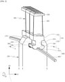
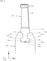
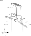
- FIGS. 2 and 3 illustrate a portion of a rotating unit in a steam turbine according to an example outside of the scope of the present invention.
- the steam turbine may include a casing (not shown) that forms the external appearance and frame thereof, a rotating unit that is rotatably installed in the casing, and a nozzle (not shown) that injects steam into the rotating unit.
- the rotating unit includes a rotatable rotor 200, which may have a disk shape, and a bucket 300 coupled to the rotor 200 to convert the energy of steam injected from the nozzle into mechanical work.
- the rotary shaft (not shown) of the rotor 200 passes through the center (not shown) of the rotor 200.
- the rotor 200 has a seating groove 210 and a dovetail groove 240, which are formed in the outer peripheral portion thereof, such that the rotor 200 is coupled with the bucket 300.
- the coupling is achieved by seating a platform 312 (to be described later) of the bucket 300 in the seating groove 210 and by engaging a dovetail protrusion 318 (to be described later) of the bucket 300 with the dovetail groove 240. Pressure welding (to be described later) completes the coupling.
- the seating groove 210 may be recessed from an outer peripheral surface of the rotor 200 toward the center of rotation of the rotor 200 in the radial direction of the rotor 200.
- the dovetail groove 240 may be further recessed from the seating groove 210 toward the center of rotation of the rotor 200 in the radial direction of the rotor 200.
- the dovetail groove 240 includes a first dovetail groove 220 that has a shape corresponding to a first dovetail protrusion 314 (to be described later) of the dovetail protrusion 318 and engages with the first dovetail protrusion 314, and a second dovetail groove 230 that has a shape corresponding to a second dovetail protrusion 316 (to be described later) of the dovetail protrusion 318 and engages with the second dovetail protrusion 316.
- the seating groove 210 and the dovetail groove 240 may extend in the rotational direction of the rotor 200 such that the bucket 300 is inserted into and is coupled to the rotor 200 in the rotational direction of the rotor 200.
- the axial direction of the rotor 200 will be referred to as a first direction D1
- the rotational direction of the rotor 200 will be referred to as a second direction D2
- the radial direction of the rotor 200 will be referred to as a third direction D3.
- the indicated axial or radial "direction" may be assumed to be either of opposite directions along a corresponding line
- the indicated rotational "direction” may be assumed to be either of opposite rotational directions.
- the root 310 includes a platform 312 formed at the blade root of the blade 320, and a dovetail protrusion 318 located opposite the blade 320 with respect to the platform 312.
- the blade root forms the base of the blade 320 opposite from the blade tip.
- the first direction length of the platform 312 may be shorter than the first direction length of the rotor such that the platform 312 is inserted into the seating groove 210 of the rotor
- the second direction length of the platform may be shorter than the second direction length of the cover 330 such that the cover 330 is pressure-welded to another cover 330 by overlapping therewith
- the third direction length of the platform may be longer than the third direction depth of the seating groove 210 such that the blade 320 protrudes outward of the seating groove 210.
- the dovetail protrusion 318 is engageable with the rotor 200, and may have a "T" shape for a reduction in cost of manufacture through shape simplification. That is, the dovetail protrusion 318 includes a first dovetail protrusion 314 that extends toward the center of rotation of the rotor 200 in the third direction D3 from the platform 312, and a second dovetail protrusion 316 that extends bidirectionally along the first direction D1 from the tip of the first dovetail protrusion 314.
- the first direction length of the first dovetail protrusion 314 may be shorter than the first direction length of the platform 312, the second direction length of the first dovetail protrusion 314 may be substantially equal to the second direction length of the platform 312, and the third direction length of the first dovetail protrusion 314 may be substantially equal to the third direction length of the platform 312.
- the first direction length of the second dovetail protrusion 316 may be longer than the first direction length of the platform 312 and the first direction length of the first dovetail protrusion 314, the second direction length of the second dovetail protrusion 316 may be substantially equal to the second direction length of the platform 312 and the second direction length of the first dovetail protrusion 314, and the third direction length of the second dovetail protrusion 316 may be substantially equal to the third direction length of the platform 312 and the third direction length of the first dovetail protrusion 314.
- the platform 312 and the dovetail protrusion 318 may extend in the second direction D2 such that the bucket 300 is inserted into and coupled to the rotor 200 in the second direction D2.
- the blade 320 may have an airfoil profile in which a blade back and a blade belly are located on opposite sides of the blade 320 along the second direction D2.
- the cover 330 is configured such that a cover 330 of a sample bucket 300 of the plurality of buckets 300 is pressure-welded to a cover 330 formed on a bucket 300 adjacent to the sample bucket 300.
- Each cover 330 is configured to have a second direction length that is longer than a reference length, where the reference length is the length of an arc obtained by dividing the circumference of a circle having a known radius by the number of buckets.
- the radius of the circle is set as the distance between the rotary shaft of the rotor 200 and the cover 330.
- the rotating unit may be configured such that the bucket 300 is twisted at a predetermined angle and is then coupled to the rotor 200 to suppress vibration and prevent a leakage of steam. That is, the root 310 of one of the plurality of buckets 300 is supported by the rotor 200 and the cover 330 of the bucket 300 is pressure-welded to the cover 330 of an adjacent bucket 300, thereby enabling the blade 320 of the bucket 300 to be twisted at a predetermined angle.
- the bucket 300 may be configured such that, when the root 310 is fixedly supported at the time when the cover 330 is pressure-welded to another cover 330, the blade 320 is twisted. That is, when the first dovetail protrusion 314 is pressure-welded in the first direction D1 by the first dovetail groove 220 and the second dovetail protrusion 316 is pressure-welded in the first direction D1 by the second dovetail groove 230, the blade 320 may be twisted by the pressure welding of the cover 330.
- the twisting of the bucket can affect the natural frequency of the rotating unit to reduce vibration, and it is possible to enhance the efficiency of the steam turbine by the tight contact between the cover 330 and another cover 330 to prevent a leakage of steam due to the gap therebetween.
- the twisting of the bucket 300 may be released during operation. That is, the root 310 is well supported by the rotor 200 when the rotational speed of the rotating unit is kept below a predetermined speed, to include a stopped state of the rotating unit, but the root 310 may not be well supported by the rotor 200 when the rotating unit exceeds the predetermined speed such that the dovetail groove 240 is splayed in the first direction D1 by centrifugal force.
- the rotating unit may further includes a bucket support means 400 for supporting the bucket 300 at a coupling portion between the rotor 200 and the bucket 300 and for supporting a twisted state of the bucket 300 based on the coupling between the rotor 200 and the bucket 300.
- the bucket support means 400 includes a keyway 410 recessed in a base surface 316a of the second dovetail protrusion 316, and a key 420 inserted into the keyway 410.
- the base surface 316a is provided to the bucket 300 at the coupling portion and faces a point of coupling between the rotor 200 and the bucket 300.
- the bucket support means 400 may be formed at the center of the base surface 316a of the second dovetail protrusion 316 of the dovetail protrusion 318 and the center of the base surface 230a of the second dovetail groove 230 of the dovetail groove 240 in order to prevent the bucket support means 400 from adversely affecting the rotational balance of the rotating unit.
- the key 420 is formed separately from the rotor 200 and the bucket 300 to more stably support the bucket 300 and prevent damage to the key 420.
- the key 420 may be made of a material having higher strength than the rotor 200 and the bucket 300. Therefore, it is possible to prevent damage to the key The 420.
- the key 420 may be made of a material having a higher coefficient of thermal expansion than the bucket 300.
- the key 420 is more strongly pressure-welded to the keyway 410 when the rotating unit is thermally expanded by heat generated during operation, it is possible to more stably support the twisting of the bucket 300.
- the key 420 may be configured such that the second direction length thereof differs from the second direction length of the keyway 410. That is, the keyway 410 and the key 420 extend in the second direction D2, in which case the keyway 410 formed in one of the plurality of buckets 300 may communicate with a keyway 410 formed in a bucket 300 adjacent to the bucket 300 and the second direction length of the key 420 may be longer than the second direction length of the keyway 410 such that the key 420 is engaged with at least two of the plurality of buckets 300.
- a plurality of keyways 410 simultaneously engaged with the same key 420 may be affected by one another through a single key 420, thereby causing the key 420 to provide a stronger reaction to the plurality of buckets 300 supported by the key 420. Therefore, it is possible to more stably support the twisted state of the plurality of buckets 300. Besides, it is possible to prevent the key 420 from rotating relative to the rotor 200 and the bucket 300 when the rotating unit rotates.
- the steam injected from the nozzle may be introduced into the bucket 300 in the first direction D1, and the steam introduced into the bucket 300 may pass through the bucket 300 while the direction of flow of the steam is changed by the bucket 300.
- impulsive force may act on the bucket 300 by the steam, so that the bucket 300 may convert the energy of steam into mechanical work while rotating in the second direction D2 together with the rotor 200.
- the rotating unit according to the present embodiment since the bucket 300 is twisted at the predetermined angle and then coupled to the rotor 200, the natural frequency of the rotating unit is changed to suppress vibration and prevent a leakage of steam between adjacent covers 330. Therefore, it is possible to enhance energy efficiency.
- the rotating unit further includes the bucket support means 400, the twisting of the bucket 300 may be maintained even during operation. That is, provided that the rotational speed of the rotating unit does not exceed the predetermined speed, the first dovetail protrusion 314 may be pressure-welded in the first direction D1 by the first dovetail groove 220 and the second dovetail protrusion 316 may be pressure-welded in the first direction D1 by the second dovetail groove 230 and the bucket support means 400.
- the keyway 410 and the key 420 have a uniform first direction length (width) in the present embodiment, they have a variable first direction length as in an embodiment illustrated in FIG. 4 . That is, the first direction length of the keyway 410 is reduced as the keyway 410 approaches the center of rotation of the rotor 200, or as the keyway 410 approaches the base surface 230a, in the third direction D3.
- the key 420 has a shape corresponding to the shape of the keyway 410 so as to be engaged to the keyway 410. That is, the first direction length of the key 420 is reduced as the key 420 approaches the center of rotation of the rotor 200, or as the key 420 approaches the base surface 316a, in the third direction D3. In this case, the effect of this embodiment may be substantially the same as that of the above embodiment. However, since the opening of the keyway 410 is relatively small in this case, it is possible to previously prevent the separation of the key 420 from the keyway 410 during operation.
- the key 420 may also be inserted into the rotor 200 as in an embodiment illustrated in FIG. 5 . That is, the bucket support means 400 may further include an auxiliary keyway 430 recessed to the center of rotation of the rotor 200 in the third direction D3 from the base surface 230a of the second dovetail groove 230.
- the key 420 may include a first insertion portion 422 that is inserted into the keyway 410, and a second insertion portion 424 that protruding toward the center of rotation of the rotor 200 in the third direction D3 from the first insertion portion 422 and is inserted into the auxiliary keyway 430.
- the auxiliary keyway 430 and the second insertion portion 424 may extend in the second direction D2.
- the effect of this embodiment may be substantially the same as that of the above embodiment.
- the bucket 300 is coupled to the rotor 200 and the key 420 in the state in which the position of the key 420 is guided by the auxiliary keyway 430 when the key 420 is assembled to the rotating unit, it is possible to easily assembly the rotating unit.
- the key 420 is simultaneously supported by the keyway 410 and the auxiliary keyway 430, it is possible to more effectively prevent the key 420 from rotating relative to the rotor 200 and the bucket 300 during operation and to more stably support the bucket 300.
- the keyway 410 and the first insertion portion 422 of the key 420 may be formed as in the embodiment of FIG. 4 and the auxiliary keyway 430 and the second insertion portion 424 of the key 420 may be formed similarly to the keyway 410 and the first insertion portion 422 of the key 420.
- the first direction length of the keyway 410 may be reduced as the keyway 410 approaches the center of rotation of the rotor 200 in the third direction D3.
- the first insertion portion 422 of the key 420 may have a shape corresponding to the shape of the keyway 410 so as to engage with the keyway 410. That is, the first direction length of the first insertion portion 422 of the key 420 may be reduced as the first insertion portion 422 approaches the center of rotation of the rotor 200 in the third direction D3.
- the first direction length of the auxiliary keyway 430 may be increased as the auxiliary keyway 430 approaches the center of rotation of the rotor 200 in the third direction D3.
- the second insertion portion 424 of the key 420 may have a shape corresponding to the shape of the auxiliary keyway 430 so as to engage with the auxiliary keyway 430. That is, the first direction length of the second insertion portion 424 of the key 420 may be increased as the second insertion portion 424 approaches the center of rotation of the rotor 200 in the third direction D3.
- the effect of this embodiment may be substantially the same as that of the above embodiment.
- the opening of the auxiliary keyway 430 is relatively small in this case, it is possible to previously prevent the separation of the key 420 from the keyway 410 and the auxiliary keyway 430 during operation.
- the movement of the bucket 300 in the third direction D3 is suppressed during operation by the second insertion portion 424 serving to prevent the separation of the key 420 from the auxiliary keyway 430 in the third direction D3, thereby reducing the force of the bucket 300 applied to the dovetail groove 240 of the rotor 200.
- the second insertion portion 424 serving to prevent the separation of the key 420 from the auxiliary keyway 430 in the third direction D3, thereby reducing the force of the bucket 300 applied to the dovetail groove 240 of the rotor 200.
- the rotating unit may also include a dovetail groove splaying prevention means as in an example illustrated in FIGS. 6 and 7 .
- the dovetail groove splaying prevention means prevents the splaying of the dovetail groove 240 during operation, to more effectively maintain the twisting of the bucket 300.
- the second dovetail protrusion 316 may include a second dovetail protrusion surface 316b that forms an acute angle with the first dovetail protrusion 314, and the second dovetail groove 230 may include a second dovetail groove surface 230b that forms a complementary angle to engage with the second dovetail protrusion surface 316b.
- the second dovetail protrusion surface 316b and the second dovetail groove surface 230b overlap in the first direction D1.
- the third direction distance between the second dovetail protrusion surface 316b and the center of rotation of the rotor 200 may increase with an increasing distance of the second dovetail protrusion surface 316b from the first dovetail protrusion 314 in the first direction D1, and the second dovetail groove surface 230b and the second dovetail protrusion surface 316b have corresponding and complementary shapes with respect to each other. That is, the third direction distance between the second dovetail groove surface 230b and the center of rotation of the rotor 200 may likewise increase with an increasing distance of the second dovetail groove surface 230b from the first dovetail protrusion 314 in the first direction D1.
- the second dovetail protrusion surface 316b prevents the second dovetail groove surface 230b from moving away from the bucket 300 in the first direction D1. As a result, it is possible to prevent the splaying of the dovetail groove 220/230 during operation.
- the root 310 of the bucket 300 is interference-fitted in the first direction D1 by the rotor 200 as well as the key 420. Therefore, it is possible to more securely support the root 310 and more effectively maintain the twisting of the bucket 300.
Landscapes
- Engineering & Computer Science (AREA)
- Mechanical Engineering (AREA)
- General Engineering & Computer Science (AREA)
- Turbine Rotor Nozzle Sealing (AREA)
Claims (9)
- Rotierende Einheit, die Folgendes umfasst:einen Rotor (200); undeine Schaufel (300), die mit dem Rotor (200) gekoppelt ist, um Fluid-Energie in mechanische Arbeit umzusetzen, wobei die gekoppelte Schaufel (300) vorab um einen vorgegebenen Winkel gedreht ist, wobei die Schaufel (300) eine Grundfläche aufweist, die einem Kopplungspunkt zwischen dem Rotor (200) und der Schaufel (300) zugewandt ist;wobei die rotierende Einheit ferner ein Schaufelträgermittel (400) umfasst, das zum Stützen eines gedrehten Zustands der Schaufel (300) auf der Grundlage der Kopplung zwischen dem Rotor (200) und der Schaufel (300) an dem Kopplungspunkt zwischen dem Rotor (200) und der Schaufel (300) vorgesehen ist, wobei das Schaufelträgermittel (400) eine Keilnut (410), die in der Grundfläche der Schaufel (300) vertieft ist, und einen Keil (420), der in die Keilnut (410) eingesetzt werden kann, umfasst, wobei der Keil (420) getrennt vom Rotor (200) und der Schaufel (300) gebildet ist und wobei sich die Keilnut (410) und der Keil (420) in einer Drehrichtung (D2) des Rotors (200) erstrecken und wobei die Keilnut (410) eine Breite aufweist, die verringert ist, je näher sich die Keilnut (410) am Drehzentrum des Rotors (200) befindet, und der Keil (420) eine Form aufweist, die der Form der Keilnut (410) entspricht, damit er sich mit der Keilnut (410) in Eingriff befindet, wenn er eingesetzt ist;wobei die Schaufel (300) eine von mehreren Schaufeln (300) ist, wobei jede Schaufel (300) Folgendes umfasst:- eine Wurzel (310), die mit dem Rotor (200) gekoppelt ist und durch den Rotor (200) und/oder das Schaufelträgermittel (400) getragen wird;- ein Blatt (320), das in einer radialen Richtung des Rotors (200) von der Wurzel (310) zu einer Blattspitze des Blatts (320) vorsteht; und- eine Abdeckung (330), die in der Drehrichtung des Rotors (200) von der Blattspitze zu einer Abdeckung (330) einer benachbarten Schaufel (300) der mehreren Schaufeln (300) vorsteht, wobei die benachbarten Abdeckungen (330) miteinander druckverschweißt sind, um den vorgegebenen Winkel der Drehung des Blatts (320) der Schaufel (300) zu arretieren; undwobei die Wurzel (310) eine Plattform (312), die an einer Blattwurzel (310) des Blatts (320) gebildet ist, und einen Schwalbenschwanzvorsprung (318), der sich von der Plattform (312) in Richtung eines Drehzentrums des Rotors (200) erstreckt, umfasst,wobei der Rotor (200) eine Aufnahmefuge (210), in der die Plattform (312) aufgenommen ist, und eine Schwalbenschwanzfuge (240), die sich mit dem Schwalbenschwanzvorsprung (318) der Wurzel (310) in Eingriff befindet, umfasst,wobei der Schwalbenschwanzvorsprung (318) einen ersten Schwalbenschwanzvorsprung (314) und einen zweiten Schwalbenschwanzvorsprung (316) aufweist,wobei die Schwalbenschwanzfuge (240) eine erste Schwalbenschwanzfuge (220) und eine zweite Schwalbenschwanzfuge (230) aufweist, undwobei eine Fläche, die dem Drehzentrum des Rotors (200) zugewandt ist, im zweiten Schwalbenschwanzvorsprung (316) eine Grundfläche (316a) des zweiten Schwalbenschwanzvorsprungs (316) ist und eine Fläche in der zweiten Schwalbenschwanzfuge (230), die der Grundfläche (316a) des zweiten Schwalbenschwanzvorsprungs (316) zugewandt ist, eine Grundfläche (230a) der zweiten Schwalbenschwanzfuge (230) ist, wobei das Schaufelträgermittel (400) zwischen der Grundfläche (316a) des zweiten Schwalbenschwanzvorsprungs (316) und der Grundfläche (230a) der zweiten Schwalbenschwanzfuge (230) gebildet ist und wobei die Grundfläche der Schaufel (300), in der die Keilnut (420) vertieft ist, die Grundfläche (316a) des zweiten Schwalbenschwanzvorsprungs (316) ist.
- Rotierende Einheit nach Anspruch 1, wobei der Keil (420) aus einem anderen Material als die Schaufel (300) hergestellt ist.
- Rotierende Einheit nach Anspruch 1 oder 2, wobei der Keil (420) aus einem Material mit einer höheren Festigkeit als die Schaufel (300) oder einem Material mit einer höheren Festigkeit und einem höheren Wärmeausdehnungskoeffizienten als die Schaufel (300) hergestellt ist.
- Rotierende Einheit nach einem der Ansprüche 1 bis 3,
wobei die Schaufel (300) eine von mehreren Schaufeln (300) ist, die Keilnut (410) von einer der mehreren Schaufeln (300) mit einer Keilnut (410) einer benachbarten Schaufel (300) in Verbindung steht und der Keil (420) in einer Drehrichtung des Rotors (200) eine Länge aufweist, die länger als die Keilnut (410) ist, derart, dass sich der Keil (420) mit mindestens zwei der mehreren Schaufeln (300) in Eingriff befindet. - Rotierende Einheit nach einem der Ansprüche 1 bis 4, wobei das Schaufelträgermittel (400) ferner eine Hilfskeilnut (430) umfasst, die in der Grundfläche (230a) der zweiten Schwalbenschwanzfuge (230) vertieft ist, und
wobei der Keil (420) einen ersten Einsetzabschnitt (422), der in die Keilnut (410) eingesetzt ist, und einen zweiten Einsetzabschnitt (424), der in die Hilfskeilnut (430) eingesetzt ist, während er vom ersten Einsetzabschnitt (422) vorsteht, umfasst. - Rotierende Einheit nach Anspruch 5, wobei die Hilfskeilnut (430) eine Breite aufweist, die vergrößert ist, je näher sich die Hilfskeilnut (430) am Drehzentrum des Rotors (200) befindet, und der zweite Einsetzabschnitt (424) des Keils (420) sich mit der Hilfskeilnut (430) in Eingriff befindet, wenn er eingesetzt ist.
- Rotierende Einheit nach einem der Ansprüche 1 bis 6, wobei der zweite Schwalbenschwanzvorsprung (316) eine zweite Schwalbenschwanzvorsprungsfläche (316b) aufweist, die sich vom ersten Schwalbenschwanzvorsprung (314) in einer axialen Richtung des Rotors (200) erstreckt,wobei die zweite Schwalbenschwanzfuge (230) eine zweite Schwalbenschwanzfugenfläche (230b) aufweist, die sich mit der zweiten Schwalbenschwanzvorsprungsfläche (316b) in Eingriff befindet, undwobei ein Abstand zwischen der zweiten Schwalbenschwanzvorsprungsfläche (316b) und dem Drehzentrum des Rotors (200) mit einem zunehmenden Abstand der zweiten Schwalbenschwanzvorsprungsfläche (316b) vom ersten Schwalbenschwanzvorsprung (314) zunimmt.
- Rotierende Einheit nach einem der Ansprüche 1 bis 7, wobei der Rotor (200) ferner Folgendes umfasst:
eine Rippe (250), die von einer Außenumfangsfläche (200) des Rotors vorsteht und sich in der radialen Richtung des Rotors (200) über einen Bereich der Aufnahmefuge (210) und der Schwalbenschwanzfuge (240) erstreckt. - Dampfturbine, die Folgendes umfasst:ein Gehäuse;die rotierende Einheit nach einem der Ansprüche 1 bis 8, die im Gehäuse drehbar vorgesehen ist; undeine Düse zum Einspritzen von Dampf in die rotierende Einheit.
Applications Claiming Priority (1)
| Application Number | Priority Date | Filing Date | Title |
|---|---|---|---|
| KR1020170042044A KR101892389B1 (ko) | 2017-03-31 | 2017-03-31 | 회전체 및 이를 포함하는 증기 터빈 |
Publications (2)
| Publication Number | Publication Date |
|---|---|
| EP3382154A1 EP3382154A1 (de) | 2018-10-03 |
| EP3382154B1 true EP3382154B1 (de) | 2022-02-16 |
Family
ID=61868208
Family Applications (1)
| Application Number | Title | Priority Date | Filing Date |
|---|---|---|---|
| EP18164952.6A Active EP3382154B1 (de) | 2017-03-31 | 2018-03-29 | Anti-aufdreh-kupplung für rotor-schaufel-baugruppe und entsprechende dampfturbine |
Country Status (3)
| Country | Link |
|---|---|
| US (1) | US10871076B2 (de) |
| EP (1) | EP3382154B1 (de) |
| KR (1) | KR101892389B1 (de) |
Families Citing this family (3)
| Publication number | Priority date | Publication date | Assignee | Title |
|---|---|---|---|---|
| US10641111B2 (en) * | 2018-08-31 | 2020-05-05 | Rolls-Royce Corporation | Turbine blade assembly with ceramic matrix composite components |
| KR102388988B1 (ko) * | 2020-08-25 | 2022-04-20 | 두산중공업 주식회사 | 로터 및 이를 포함하는 터보머신 |
| EP4481209B1 (de) * | 2023-06-19 | 2025-11-12 | Rolls-Royce plc | Halterung für komponenten |
Citations (3)
| Publication number | Priority date | Publication date | Assignee | Title |
|---|---|---|---|---|
| US5100292A (en) * | 1990-03-19 | 1992-03-31 | General Electric Company | Gas turbine engine blade |
| US5509784A (en) * | 1994-07-27 | 1996-04-23 | General Electric Co. | Turbine bucket and wheel assembly with integral bucket shroud |
| US20160186582A1 (en) * | 2014-12-26 | 2016-06-30 | Snecma | Turbomachine rotor with optimised bearing surfaces |
Family Cites Families (11)
| Publication number | Priority date | Publication date | Assignee | Title |
|---|---|---|---|---|
| US2809801A (en) | 1952-04-18 | 1957-10-15 | Ingersoll Rand Co | Turbine rotor construction |
| JPS63168201U (de) * | 1987-04-24 | 1988-11-01 | ||
| US7261518B2 (en) * | 2005-03-24 | 2007-08-28 | Siemens Demag Delaval Turbomachinery, Inc. | Locking arrangement for radial entry turbine blades |
| JP4673732B2 (ja) | 2005-12-01 | 2011-04-20 | 株式会社東芝 | タービン動翼および蒸気タービン |
| EP1803899A1 (de) | 2006-01-02 | 2007-07-04 | Siemens Aktiengesellschaft | Schlussbaugruppe für einen Schaufelkranz einer Strömungsmaschine |
| JP5372685B2 (ja) * | 2009-09-30 | 2013-12-18 | 株式会社日立製作所 | タービン動翼の固定構造 |
| US8651820B2 (en) * | 2010-07-14 | 2014-02-18 | General Electric Company | Dovetail connection for turbine rotating blade and rotor wheel |
| US8764402B2 (en) | 2011-06-09 | 2014-07-01 | General Electric Company | Turbomachine blade locking system |
| EP2669477B1 (de) | 2012-05-31 | 2017-04-05 | General Electric Technology GmbH | Deckplatte für Schaufeln |
| JP6296694B2 (ja) | 2013-04-22 | 2018-03-20 | 株式会社東芝 | タービン動翼及びタービン |
| JP6329471B2 (ja) | 2014-09-26 | 2018-05-23 | 新日本造機株式会社 | タービン |
-
2017
- 2017-03-31 KR KR1020170042044A patent/KR101892389B1/ko active Active
-
2018
- 2018-03-22 US US15/928,120 patent/US10871076B2/en active Active
- 2018-03-29 EP EP18164952.6A patent/EP3382154B1/de active Active
Patent Citations (3)
| Publication number | Priority date | Publication date | Assignee | Title |
|---|---|---|---|---|
| US5100292A (en) * | 1990-03-19 | 1992-03-31 | General Electric Company | Gas turbine engine blade |
| US5509784A (en) * | 1994-07-27 | 1996-04-23 | General Electric Co. | Turbine bucket and wheel assembly with integral bucket shroud |
| US20160186582A1 (en) * | 2014-12-26 | 2016-06-30 | Snecma | Turbomachine rotor with optimised bearing surfaces |
Also Published As
| Publication number | Publication date |
|---|---|
| US20180283188A1 (en) | 2018-10-04 |
| EP3382154A1 (de) | 2018-10-03 |
| US10871076B2 (en) | 2020-12-22 |
| KR101892389B1 (ko) | 2018-08-27 |
Similar Documents
| Publication | Publication Date | Title |
|---|---|---|
| US5100158A (en) | Compliant finer seal | |
| US5509784A (en) | Turbine bucket and wheel assembly with integral bucket shroud | |
| EP0297120B1 (de) | Dichtung zwischen den schaufeln eines turbomaschinenrotors | |
| EP1867837B1 (de) | Dämpfungssystem für Turbinenschaufeln | |
| US6884028B2 (en) | Turbomachinery blade retention system | |
| EP3382154B1 (de) | Anti-aufdreh-kupplung für rotor-schaufel-baugruppe und entsprechende dampfturbine | |
| KR102273496B1 (ko) | 터빈 버킷 클로져 조립체 및 그 조립 방법 | |
| US7618234B2 (en) | Hook ring segment for a compressor vane | |
| JP2005155620A (ja) | タービン用のシール組立体、シール組立体を含むバケット/タービン、並びにタービンの回転及び固定構成部品間の境界面をシールする方法 | |
| US11162378B2 (en) | Turbine apparatus | |
| KR101985093B1 (ko) | 블레이드 팁의 실링구조와 이를 포함하는 가스터빈 | |
| US7628581B2 (en) | Rotating machine | |
| JP6066948B2 (ja) | シュラウド、動翼体、及び回転機械 | |
| RU2651697C2 (ru) | Барабан ротора осевой турбомашины и турбомашина | |
| US6428279B1 (en) | Low windage loss, light weight closure bucket design and related method | |
| US9097129B2 (en) | Segmented seal with ship lap ends | |
| US11365646B2 (en) | Rotary machine and seal member | |
| JP7385992B2 (ja) | 回転体の動翼およびディスク | |
| CN100404795C (zh) | 涡轮机以及用于涡轮机的转子 | |
| US20220025819A1 (en) | Turbine apparatus | |
| KR102498006B1 (ko) | 원심력에 최적화된 접촉면을 갖는 회전자 | |
| JP7269029B2 (ja) | 動翼及び回転機械 | |
| US20140205460A1 (en) | Method and system for self-locking a closure bucket in a rotary machine | |
| CN113503362A (zh) | 用于转子的密封环和具有这种密封环的转子 | |
| KR101874242B1 (ko) | 터빈 회전체 및 이를 포함하는 증기 터빈 |
Legal Events
| Date | Code | Title | Description |
|---|---|---|---|
| PUAI | Public reference made under article 153(3) epc to a published international application that has entered the european phase |
Free format text: ORIGINAL CODE: 0009012 |
|
| STAA | Information on the status of an ep patent application or granted ep patent |
Free format text: STATUS: REQUEST FOR EXAMINATION WAS MADE |
|
| 17P | Request for examination filed |
Effective date: 20180329 |
|
| AK | Designated contracting states |
Kind code of ref document: A1 Designated state(s): AL AT BE BG CH CY CZ DE DK EE ES FI FR GB GR HR HU IE IS IT LI LT LU LV MC MK MT NL NO PL PT RO RS SE SI SK SM TR |
|
| AX | Request for extension of the european patent |
Extension state: BA ME |
|
| RBV | Designated contracting states (corrected) |
Designated state(s): AL AT BE BG CH CY CZ DE DK EE ES FI FR GB GR HR HU IE IS IT LI LT LU LV MC MK MT NL NO PL PT RO RS SE SI SK SM TR |
|
| STAA | Information on the status of an ep patent application or granted ep patent |
Free format text: STATUS: EXAMINATION IS IN PROGRESS |
|
| RIC1 | Information provided on ipc code assigned before grant |
Ipc: F01D 5/22 20060101ALN20190801BHEP Ipc: F01D 5/30 20060101ALI20190801BHEP Ipc: F01D 5/26 20060101AFI20190801BHEP Ipc: F01D 5/32 20060101ALI20190801BHEP |
|
| 17Q | First examination report despatched |
Effective date: 20190812 |
|
| RIC1 | Information provided on ipc code assigned before grant |
Ipc: F01D 5/22 20060101ALN20210503BHEP Ipc: F01D 5/32 20060101ALI20210503BHEP Ipc: F01D 5/30 20060101ALI20210503BHEP Ipc: F01D 5/26 20060101AFI20210503BHEP |
|
| RIC1 | Information provided on ipc code assigned before grant |
Ipc: F01D 5/22 20060101ALN20210628BHEP Ipc: F01D 5/32 20060101ALI20210628BHEP Ipc: F01D 5/30 20060101ALI20210628BHEP Ipc: F01D 5/26 20060101AFI20210628BHEP |
|
| RIC1 | Information provided on ipc code assigned before grant |
Ipc: F01D 5/22 20060101ALN20210819BHEP Ipc: F01D 5/32 20060101ALI20210819BHEP Ipc: F01D 5/30 20060101ALI20210819BHEP Ipc: F01D 5/26 20060101AFI20210819BHEP |
|
| GRAP | Despatch of communication of intention to grant a patent |
Free format text: ORIGINAL CODE: EPIDOSNIGR1 |
|
| STAA | Information on the status of an ep patent application or granted ep patent |
Free format text: STATUS: GRANT OF PATENT IS INTENDED |
|
| INTG | Intention to grant announced |
Effective date: 20211004 |
|
| GRAS | Grant fee paid |
Free format text: ORIGINAL CODE: EPIDOSNIGR3 |
|
| GRAA | (expected) grant |
Free format text: ORIGINAL CODE: 0009210 |
|
| STAA | Information on the status of an ep patent application or granted ep patent |
Free format text: STATUS: THE PATENT HAS BEEN GRANTED |
|
| AK | Designated contracting states |
Kind code of ref document: B1 Designated state(s): AL AT BE BG CH CY CZ DE DK EE ES FI FR GB GR HR HU IE IS IT LI LT LU LV MC MK MT NL NO PL PT RO RS SE SI SK SM TR |
|
| REG | Reference to a national code |
Ref country code: GB Ref legal event code: FG4D |
|
| REG | Reference to a national code |
Ref country code: CH Ref legal event code: EP |
|
| REG | Reference to a national code |
Ref country code: DE Ref legal event code: R096 Ref document number: 602018030802 Country of ref document: DE |
|
| REG | Reference to a national code |
Ref country code: AT Ref legal event code: REF Ref document number: 1469002 Country of ref document: AT Kind code of ref document: T Effective date: 20220315 |
|
| REG | Reference to a national code |
Ref country code: IE Ref legal event code: FG4D |
|
| REG | Reference to a national code |
Ref country code: LT Ref legal event code: MG9D |
|
| REG | Reference to a national code |
Ref country code: NL Ref legal event code: MP Effective date: 20220216 |
|
| REG | Reference to a national code |
Ref country code: AT Ref legal event code: MK05 Ref document number: 1469002 Country of ref document: AT Kind code of ref document: T Effective date: 20220216 |
|
| PG25 | Lapsed in a contracting state [announced via postgrant information from national office to epo] |
Ref country code: SE Free format text: LAPSE BECAUSE OF FAILURE TO SUBMIT A TRANSLATION OF THE DESCRIPTION OR TO PAY THE FEE WITHIN THE PRESCRIBED TIME-LIMIT Effective date: 20220216 Ref country code: RS Free format text: LAPSE BECAUSE OF FAILURE TO SUBMIT A TRANSLATION OF THE DESCRIPTION OR TO PAY THE FEE WITHIN THE PRESCRIBED TIME-LIMIT Effective date: 20220216 Ref country code: PT Free format text: LAPSE BECAUSE OF FAILURE TO SUBMIT A TRANSLATION OF THE DESCRIPTION OR TO PAY THE FEE WITHIN THE PRESCRIBED TIME-LIMIT Effective date: 20220616 Ref country code: NO Free format text: LAPSE BECAUSE OF FAILURE TO SUBMIT A TRANSLATION OF THE DESCRIPTION OR TO PAY THE FEE WITHIN THE PRESCRIBED TIME-LIMIT Effective date: 20220516 Ref country code: NL Free format text: LAPSE BECAUSE OF FAILURE TO SUBMIT A TRANSLATION OF THE DESCRIPTION OR TO PAY THE FEE WITHIN THE PRESCRIBED TIME-LIMIT Effective date: 20220216 Ref country code: LT Free format text: LAPSE BECAUSE OF FAILURE TO SUBMIT A TRANSLATION OF THE DESCRIPTION OR TO PAY THE FEE WITHIN THE PRESCRIBED TIME-LIMIT Effective date: 20220216 Ref country code: HR Free format text: LAPSE BECAUSE OF FAILURE TO SUBMIT A TRANSLATION OF THE DESCRIPTION OR TO PAY THE FEE WITHIN THE PRESCRIBED TIME-LIMIT Effective date: 20220216 Ref country code: ES Free format text: LAPSE BECAUSE OF FAILURE TO SUBMIT A TRANSLATION OF THE DESCRIPTION OR TO PAY THE FEE WITHIN THE PRESCRIBED TIME-LIMIT Effective date: 20220216 Ref country code: BG Free format text: LAPSE BECAUSE OF FAILURE TO SUBMIT A TRANSLATION OF THE DESCRIPTION OR TO PAY THE FEE WITHIN THE PRESCRIBED TIME-LIMIT Effective date: 20220516 |
|
| PG25 | Lapsed in a contracting state [announced via postgrant information from national office to epo] |
Ref country code: PL Free format text: LAPSE BECAUSE OF FAILURE TO SUBMIT A TRANSLATION OF THE DESCRIPTION OR TO PAY THE FEE WITHIN THE PRESCRIBED TIME-LIMIT Effective date: 20220216 Ref country code: LV Free format text: LAPSE BECAUSE OF FAILURE TO SUBMIT A TRANSLATION OF THE DESCRIPTION OR TO PAY THE FEE WITHIN THE PRESCRIBED TIME-LIMIT Effective date: 20220216 Ref country code: GR Free format text: LAPSE BECAUSE OF FAILURE TO SUBMIT A TRANSLATION OF THE DESCRIPTION OR TO PAY THE FEE WITHIN THE PRESCRIBED TIME-LIMIT Effective date: 20220517 Ref country code: FI Free format text: LAPSE BECAUSE OF FAILURE TO SUBMIT A TRANSLATION OF THE DESCRIPTION OR TO PAY THE FEE WITHIN THE PRESCRIBED TIME-LIMIT Effective date: 20220216 Ref country code: AT Free format text: LAPSE BECAUSE OF FAILURE TO SUBMIT A TRANSLATION OF THE DESCRIPTION OR TO PAY THE FEE WITHIN THE PRESCRIBED TIME-LIMIT Effective date: 20220216 |
|
| PG25 | Lapsed in a contracting state [announced via postgrant information from national office to epo] |
Ref country code: IS Free format text: LAPSE BECAUSE OF FAILURE TO SUBMIT A TRANSLATION OF THE DESCRIPTION OR TO PAY THE FEE WITHIN THE PRESCRIBED TIME-LIMIT Effective date: 20220617 |
|
| PG25 | Lapsed in a contracting state [announced via postgrant information from national office to epo] |
Ref country code: SM Free format text: LAPSE BECAUSE OF FAILURE TO SUBMIT A TRANSLATION OF THE DESCRIPTION OR TO PAY THE FEE WITHIN THE PRESCRIBED TIME-LIMIT Effective date: 20220216 Ref country code: SK Free format text: LAPSE BECAUSE OF FAILURE TO SUBMIT A TRANSLATION OF THE DESCRIPTION OR TO PAY THE FEE WITHIN THE PRESCRIBED TIME-LIMIT Effective date: 20220216 Ref country code: RO Free format text: LAPSE BECAUSE OF FAILURE TO SUBMIT A TRANSLATION OF THE DESCRIPTION OR TO PAY THE FEE WITHIN THE PRESCRIBED TIME-LIMIT Effective date: 20220216 Ref country code: EE Free format text: LAPSE BECAUSE OF FAILURE TO SUBMIT A TRANSLATION OF THE DESCRIPTION OR TO PAY THE FEE WITHIN THE PRESCRIBED TIME-LIMIT Effective date: 20220216 Ref country code: DK Free format text: LAPSE BECAUSE OF FAILURE TO SUBMIT A TRANSLATION OF THE DESCRIPTION OR TO PAY THE FEE WITHIN THE PRESCRIBED TIME-LIMIT Effective date: 20220216 |
|
| REG | Reference to a national code |
Ref country code: CH Ref legal event code: PL |
|
| REG | Reference to a national code |
Ref country code: DE Ref legal event code: R097 Ref document number: 602018030802 Country of ref document: DE |
|
| PG25 | Lapsed in a contracting state [announced via postgrant information from national office to epo] |
Ref country code: MC Free format text: LAPSE BECAUSE OF FAILURE TO SUBMIT A TRANSLATION OF THE DESCRIPTION OR TO PAY THE FEE WITHIN THE PRESCRIBED TIME-LIMIT Effective date: 20220216 Ref country code: AL Free format text: LAPSE BECAUSE OF FAILURE TO SUBMIT A TRANSLATION OF THE DESCRIPTION OR TO PAY THE FEE WITHIN THE PRESCRIBED TIME-LIMIT Effective date: 20220216 |
|
| REG | Reference to a national code |
Ref country code: BE Ref legal event code: MM Effective date: 20220331 |
|
| PLBE | No opposition filed within time limit |
Free format text: ORIGINAL CODE: 0009261 |
|
| STAA | Information on the status of an ep patent application or granted ep patent |
Free format text: STATUS: NO OPPOSITION FILED WITHIN TIME LIMIT |
|
| 26N | No opposition filed |
Effective date: 20221117 |
|
| GBPC | Gb: european patent ceased through non-payment of renewal fee |
Effective date: 20220516 |
|
| PG25 | Lapsed in a contracting state [announced via postgrant information from national office to epo] |
Ref country code: LU Free format text: LAPSE BECAUSE OF NON-PAYMENT OF DUE FEES Effective date: 20220329 Ref country code: LI Free format text: LAPSE BECAUSE OF NON-PAYMENT OF DUE FEES Effective date: 20220331 Ref country code: IE Free format text: LAPSE BECAUSE OF NON-PAYMENT OF DUE FEES Effective date: 20220329 Ref country code: FR Free format text: LAPSE BECAUSE OF NON-PAYMENT OF DUE FEES Effective date: 20220416 Ref country code: CH Free format text: LAPSE BECAUSE OF NON-PAYMENT OF DUE FEES Effective date: 20220331 |
|
| PG25 | Lapsed in a contracting state [announced via postgrant information from national office to epo] |
Ref country code: SI Free format text: LAPSE BECAUSE OF FAILURE TO SUBMIT A TRANSLATION OF THE DESCRIPTION OR TO PAY THE FEE WITHIN THE PRESCRIBED TIME-LIMIT Effective date: 20220216 Ref country code: BE Free format text: LAPSE BECAUSE OF NON-PAYMENT OF DUE FEES Effective date: 20220331 |
|
| PG25 | Lapsed in a contracting state [announced via postgrant information from national office to epo] |
Ref country code: GB Free format text: LAPSE BECAUSE OF NON-PAYMENT OF DUE FEES Effective date: 20220516 |
|
| PG25 | Lapsed in a contracting state [announced via postgrant information from national office to epo] |
Ref country code: IT Free format text: LAPSE BECAUSE OF FAILURE TO SUBMIT A TRANSLATION OF THE DESCRIPTION OR TO PAY THE FEE WITHIN THE PRESCRIBED TIME-LIMIT Effective date: 20220216 |
|
| PG25 | Lapsed in a contracting state [announced via postgrant information from national office to epo] |
Ref country code: HU Free format text: LAPSE BECAUSE OF FAILURE TO SUBMIT A TRANSLATION OF THE DESCRIPTION OR TO PAY THE FEE WITHIN THE PRESCRIBED TIME-LIMIT; INVALID AB INITIO Effective date: 20180329 |
|
| PG25 | Lapsed in a contracting state [announced via postgrant information from national office to epo] |
Ref country code: MK Free format text: LAPSE BECAUSE OF FAILURE TO SUBMIT A TRANSLATION OF THE DESCRIPTION OR TO PAY THE FEE WITHIN THE PRESCRIBED TIME-LIMIT Effective date: 20220216 Ref country code: CY Free format text: LAPSE BECAUSE OF FAILURE TO SUBMIT A TRANSLATION OF THE DESCRIPTION OR TO PAY THE FEE WITHIN THE PRESCRIBED TIME-LIMIT Effective date: 20220216 |
|
| PG25 | Lapsed in a contracting state [announced via postgrant information from national office to epo] |
Ref country code: MT Free format text: LAPSE BECAUSE OF FAILURE TO SUBMIT A TRANSLATION OF THE DESCRIPTION OR TO PAY THE FEE WITHIN THE PRESCRIBED TIME-LIMIT Effective date: 20220216 |
|
| PG25 | Lapsed in a contracting state [announced via postgrant information from national office to epo] |
Ref country code: TR Free format text: LAPSE BECAUSE OF FAILURE TO SUBMIT A TRANSLATION OF THE DESCRIPTION OR TO PAY THE FEE WITHIN THE PRESCRIBED TIME-LIMIT Effective date: 20220216 |
|
| PGFP | Annual fee paid to national office [announced via postgrant information from national office to epo] |
Ref country code: DE Payment date: 20260102 Year of fee payment: 9 |
|
| PGFP | Annual fee paid to national office [announced via postgrant information from national office to epo] |
Ref country code: CZ Payment date: 20260323 Year of fee payment: 9 |