EP3382163B1 - Système de lubrification de moteur à turbine à gaz, moteur à turbine à gaz comportant un système de pompe de suralimentation et procédé correspondant - Google Patents
Système de lubrification de moteur à turbine à gaz, moteur à turbine à gaz comportant un système de pompe de suralimentation et procédé correspondant Download PDFInfo
- Publication number
- EP3382163B1 EP3382163B1 EP18165527.5A EP18165527A EP3382163B1 EP 3382163 B1 EP3382163 B1 EP 3382163B1 EP 18165527 A EP18165527 A EP 18165527A EP 3382163 B1 EP3382163 B1 EP 3382163B1
- Authority
- EP
- European Patent Office
- Prior art keywords
- boost pump
- fluid flow
- fluid
- boost
- pump
- Prior art date
- Legal status (The legal status is an assumption and is not a legal conclusion. Google has not performed a legal analysis and makes no representation as to the accuracy of the status listed.)
- Active
Links
Images


Classifications
-
- F—MECHANICAL ENGINEERING; LIGHTING; HEATING; WEAPONS; BLASTING
- F01—MACHINES OR ENGINES IN GENERAL; ENGINE PLANTS IN GENERAL; STEAM ENGINES
- F01D—NON-POSITIVE DISPLACEMENT MACHINES OR ENGINES, e.g. STEAM TURBINES
- F01D25/00—Component parts, details, or accessories, not provided for in, or of interest apart from, other groups
- F01D25/16—Arrangement of bearings; Supporting or mounting bearings in casings
- F01D25/162—Bearing supports
- F01D25/164—Flexible supports; Vibration damping means associated with the bearing
-
- F—MECHANICAL ENGINEERING; LIGHTING; HEATING; WEAPONS; BLASTING
- F01—MACHINES OR ENGINES IN GENERAL; ENGINE PLANTS IN GENERAL; STEAM ENGINES
- F01D—NON-POSITIVE DISPLACEMENT MACHINES OR ENGINES, e.g. STEAM TURBINES
- F01D19/00—Starting of machines or engines; Regulating, controlling, or safety means in connection therewith
-
- F—MECHANICAL ENGINEERING; LIGHTING; HEATING; WEAPONS; BLASTING
- F01—MACHINES OR ENGINES IN GENERAL; ENGINE PLANTS IN GENERAL; STEAM ENGINES
- F01D—NON-POSITIVE DISPLACEMENT MACHINES OR ENGINES, e.g. STEAM TURBINES
- F01D25/00—Component parts, details, or accessories, not provided for in, or of interest apart from, other groups
- F01D25/18—Lubricating arrangements
- F01D25/20—Lubricating arrangements using lubrication pumps
-
- F—MECHANICAL ENGINEERING; LIGHTING; HEATING; WEAPONS; BLASTING
- F02—COMBUSTION ENGINES; HOT-GAS OR COMBUSTION-PRODUCT ENGINE PLANTS
- F02K—JET-PROPULSION PLANTS
- F02K3/00—Plants including a gas turbine driving a compressor or a ducted fan
- F02K3/02—Plants including a gas turbine driving a compressor or a ducted fan in which part of the working fluid by-passes the turbine and combustion chamber
- F02K3/04—Plants including a gas turbine driving a compressor or a ducted fan in which part of the working fluid by-passes the turbine and combustion chamber the plant including ducted fans, i.e. fans with high volume, low pressure outputs, for augmenting the jet thrust, e.g. of double-flow type
- F02K3/06—Plants including a gas turbine driving a compressor or a ducted fan in which part of the working fluid by-passes the turbine and combustion chamber the plant including ducted fans, i.e. fans with high volume, low pressure outputs, for augmenting the jet thrust, e.g. of double-flow type with front fan
-
- F—MECHANICAL ENGINEERING; LIGHTING; HEATING; WEAPONS; BLASTING
- F05—INDEXING SCHEMES RELATING TO ENGINES OR PUMPS IN VARIOUS SUBCLASSES OF CLASSES F01-F04
- F05D—INDEXING SCHEME FOR ASPECTS RELATING TO NON-POSITIVE-DISPLACEMENT MACHINES OR ENGINES, GAS-TURBINES OR JET-PROPULSION PLANTS
- F05D2220/00—Application
- F05D2220/30—Application in turbines
- F05D2220/32—Application in turbines in gas turbines
-
- F—MECHANICAL ENGINEERING; LIGHTING; HEATING; WEAPONS; BLASTING
- F05—INDEXING SCHEMES RELATING TO ENGINES OR PUMPS IN VARIOUS SUBCLASSES OF CLASSES F01-F04
- F05D—INDEXING SCHEME FOR ASPECTS RELATING TO NON-POSITIVE-DISPLACEMENT MACHINES OR ENGINES, GAS-TURBINES OR JET-PROPULSION PLANTS
- F05D2240/00—Components
- F05D2240/60—Shafts
-
- F—MECHANICAL ENGINEERING; LIGHTING; HEATING; WEAPONS; BLASTING
- F05—INDEXING SCHEMES RELATING TO ENGINES OR PUMPS IN VARIOUS SUBCLASSES OF CLASSES F01-F04
- F05D—INDEXING SCHEME FOR ASPECTS RELATING TO NON-POSITIVE-DISPLACEMENT MACHINES OR ENGINES, GAS-TURBINES OR JET-PROPULSION PLANTS
- F05D2260/00—Function
- F05D2260/96—Preventing, counteracting or reducing vibration or noise
-
- F—MECHANICAL ENGINEERING; LIGHTING; HEATING; WEAPONS; BLASTING
- F05—INDEXING SCHEMES RELATING TO ENGINES OR PUMPS IN VARIOUS SUBCLASSES OF CLASSES F01-F04
- F05D—INDEXING SCHEME FOR ASPECTS RELATING TO NON-POSITIVE-DISPLACEMENT MACHINES OR ENGINES, GAS-TURBINES OR JET-PROPULSION PLANTS
- F05D2260/00—Function
- F05D2260/98—Lubrication
Definitions
- Gas turbine engines are often configured to include a fan section, a low pressure compressor section, a high pressure compressor section, a combustor section, a low pressure turbine section, a high pressure turbine section, a low speed spool, and a high speed spool.
- the fan section may be configured to drive air along a bypass flow path, while the compressor section drives air along a core flow path for compression and communication into the combustor section then expansion through the turbine section.
- the low speed spool and the high speed spool are mounted for rotation about an engine central longitudinal axis relative to an engine static structure via several bearing systems.
- the low speed spool generally interconnects the fan section, the low pressure compressor section and the low pressure turbine section.
- the high speed spool generally interconnects the high pressure compressor section and the high pressure turbine section.
- the combustor section is disposed between the high pressure compressor section and the high pressure turbine section.
- JP S62 107206 A discloses a prior art jack up device for the shaft of a turbine generator.
- a lubrication system for a gas turbine engine having a plurality of components is provided as recited in claim 1.
- a gas turbine engine which the applicant expressly reserves the right to claim independently, is provided as recited in claim 3.
- a method of supplying a fluid to at least one fluid damped structure disposed within a bearing compartment of a gas turbine engine is provided as recited in claim 11.
- connections are set forth between elements in the following description and in the drawings (the contents of which are included in this disclosure by way of reference). It is noted that these connections are general and, unless specified otherwise, may be direct or indirect and that this specification is not intended to be limiting in this respect.
- a coupling between two or more entities may refer to a direct connection or an indirect connection.
- An indirect connection may incorporate one or more intervening entities.
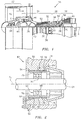
- a two-spool turbofan type gas turbine engine 20 is shown (e.g., see FIG. 1 ).
- This exemplary embodiment of a gas turbine engine includes a fan section 22, a compressor section 24, a combustor section 26, a turbine section 28, a main lubrication system, and a boost pump system in fluid communication with one or more fluid damped structures.
- the fan section 22 drives air along a bypass flow path B in a bypass duct, while the compressor section 24 drives air along a core flow path C for compression and communication into the combustor section 26 then expansion through the turbine section 28.
- the exemplary engine 20 shown in FIG. 1 includes a low speed spool 30 and a high speed spool 32 mounted for rotation about an engine central longitudinal axis A relative to an engine static structure 36 via several bearing systems 38. It should be understood that the location, number, and characteristics of bearing systems 38 may vary to suit the particular application.
- the low speed spool 30 generally includes an inner shaft 40 that interconnects a fan 42, a low pressure compressor 44 and a low pressure turbine 46.
- the inner shaft 40 is connected to the fan 42 through a speed change mechanism, which in exemplary gas turbine engine 20 is illustrated as a geared architecture 48 to drive the fan 42 at a lower speed than the low speed spool 30.
- the high speed spool 32 includes an outer shaft 50 that interconnects a high pressure compressor 52 and high pressure turbine 54.
- a combustor 56 is arranged in exemplary gas turbine 20 between the high pressure compressor 52 and the high pressure turbine 54.
- the inner shaft 40 and the outer shaft 50 are concentric and rotate via bearing systems 38 about the engine central longitudinal axis "A" which is collinear with their longitudinal axes.
- the core airflow is compressed by the low pressure compressor 44 then the high pressure compressor 52, mixed and burned with fuel in the combustor 56, then expanded over the high pressure turbine 54 and low pressure turbine 46.
- the turbines 46, 54 rotationally drive the respective low speed spool 30 and high speed spool 32 in response to the expansion.
- geared architecture 48 may be located aft of combustor section 26 or even aft of turbine section 28, and fan section 22 may be positioned forward or aft of the location of geared architecture 48.
- the gas turbine engine 20 diagrammatically depicted in FIG. 1 is one example of a high-bypass geared aircraft engine.
- the gas turbine engine 20 may have a bypass ratio that is greater than about six (6), with an example embodiment being greater than about ten (10)
- the geared architecture 48 may be an epicyclic gear train, such as a planetary gear system or other gear system, with a gear reduction ratio of greater than about 2.3
- the low pressure turbine 46 may have a pressure ratio that is greater than about five.
- the gas turbine engine 20 bypass ratio is greater than about ten (10:1)
- the fan diameter is significantly larger than that of the low pressure compressor 44
- the low pressure turbine 46 has a pressure ratio that is greater than about five 5:1.
- the low pressure turbine 46 pressure ratio is pressure measured prior to inlet of low pressure turbine 46 as related to the pressure at the outlet of the low pressure turbine 46 prior to an exhaust nozzle.
- the geared architecture 48 may be an epicycle gear train, such as a planetary gear system or other gear system, with a gear reduction ratio of greater than about 2.3:1. It should be understood, however, that the above parameters are only exemplary of one or more embodiments of a geared architecture engine and that the present disclosure is applicable to other gas turbine engines including direct drive turbofans.
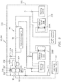
- FIG. 2 is a simplified diagrammatic cross-sectional view of a portion of a gas turbine engine showing a typical support structure 62 for a rotor shaft 61; e.g., a shaft section of a high speed spool.
- the support structure 62 includes a bearing 63 and its bearing housing 64, and an adjacent stator structure 66.
- the rotor shaft 61 is rotatable about an axis of rotation A r within a range of rotational velocities.
- the bearing 63 is represented in this particular embodiment as one having rolling elements such as balls 68 disposed between an inner race 70 and an outer race 72.
- the inner race 70 engages the rotor shaft 61.
- the bearing housing 64 is nonrotating and has an outer surface 74 and an inner surface 76.
- the bearing housing 64 supports the rotating components of the bearing 63 such as the inner race 70 and the balls 68 of the bearing 63.
- the outer race 72 engages the balls 68 and is engaged by the inner surface 76 of the bearing housing 64.
- the adjacent stator structure 66 of the support structure 62 includes a cylindrical surface 78 facing inwardly which is spaced radially from the outwardly facing cylindrical surface 74 of the bearing housing 64 thereby defining a portion of an annular damping chamber 80.
- the stator structure 66 includes structure configured to supply damping oil to the damping chamber 80; e.g., one or more inlet conduits 82.
- a pair of ring seals 84 are disposed between the bearing housing 64 and the stator structure 66.
- the ring seals 84 are spaced axially apart and extend circumferentially about the axis of the engine.
- Each ring seal 84 extends radially between and engages the bearing housing 64 and the stator structure 66 to define a portion of the damping chamber 80.
- the ring seals 84 may not be absolutely fluid tight and may include features configured to vent the damping chamber 80; e.g., passages (not shown) extending through the ring seals 84 that provide a fluid flow path between the damping chamber 80 and the exterior of the damping chamber 80.
- FIG. 2 is a non-limiting diagrammatic representation of a fluid damping structure, and the present disclosure is not limited thereto. In some embodiments, the present disclosure may be used with a plurality of different types/configurations of fluid damping structures within a gas turbine engine 20.
- the main lubrication system is configured to cycle a lubricant to and from one or more engine components (e.g., bearings, etc.), which lubricant is used to lubricate and/or cool various parts of the gas turbine engine 20.
- the main lubrication system 88 may include a lubricant storage tank 90 for storing a quantity of lubricant and may include a main supply pump 92 for drawing a supply of lubricant from the lubricant storage tank 90 and passing that lubricant to the one or more engine components.
- the main supply pump 92 includes at least one fluid inlet port 93 and at least one fluid outlet port 95.
- the main lubrication system 88 as may be used with the present disclosure is not limited to including any particular type of main supply pump 92.
- the main supply pump 92 is a positive displacement pump configured to produce lubricant output at parameters that vary as a function of the rotational speed of an engine spool.
- the main supply pump 92 is mechanically driven off of the high speed spool that connects the high pressure compressor section and the high pressure turbine section.
- the main lubrication system may include one or more heat exchangers 94 (e.g., a two-fluid heat exchanger such as an air/oil, or a fuel/oil, or an oil/oil type heat exchanger wherein a lubricating fluid is respectively cooled by air, fuel, or lubricant at a lower temperature).
- the main lubrication system 88 may include a plurality of components for controlling lubricant flow parameters (e.g., pressure, flow rate, etc.); e.g., one or more valves and one or more fluid metering devices disposed at various locations within the main lubrication system 88 to permit fluidic control of lubricant passing through the main lubrication system 88.
- the one or more valves may include valves configured to permit or prevent fluid flow (e.g., "shut off valves"), one or more valves configured to regulate flow (e.g., shuttle valves, reduction valves, bypass valves, etc.).
- the one or more fluid metering valves may include metering orifices (e.g., to control a fluid flow rate).
- the present disclosure is not limited to any particular type or configuration main lubrication system 88, and therefore is not limited to the use of particular components for controlling flow parameters within the main lubrication system 88.
- Non-limiting diagrammatic examples of main lubrication systems 88, including components for controlling flow parameters incorporated therein, are provided below.
- conduits configured to contain lubricant fluid flow.
- Conduit refers to any enclosed structure (e.g., piping) through which a fluid may be passed.
- gas turbine engine lubricants are known in the public and will not therefore be discussed further herein. The present disclosure is not limited to use with any particular gas turbine engine lubricant.
- Typical lubricants used within a gas turbine engine have a viscosity in the range of about 25 to 1.5 centistokes within the typical engine operating temperature range (1 centistoke is equal to 1 mm 2 / s ).
- the boost pump may be driven by a mechanical power source (“MPS") that is driven directly or indirectly by an engine spool shaft; e.g., by a driveshaft of an accessory gearbox that is driven directly or indirectly from an engine spool shaft.
- MPS mechanical power source
- both the boost pump and the main supply pump 92 may be driven by the same accessory gearbox driveshaft.
- the boost pump and the main supply pump 92 may be driven at different rotational speeds; e.g., the accessory gearbox, or other gearing may provide driveshafts that operate at different rotational speeds.
- Embodiments of the present disclosure that utilize a mechanically powered boost pump are not limited to any particular drive configuration.
- the present disclosure is not limited to a particular type of mechanically powered boost pump.
- Non-limiting examples of acceptable mechanically powered boost pumps include positive displacement type pumps, and centrifugal type pumps, and the like.
- the boost pump system 96 may include one or more components configured to permit or prevent fluid flow (e.g., "shut off valves") to the boost pump and/or to engine components in selective fluid communication with the boost pump, one or more components configured to regulate flow (e.g., bypass valves, metering orifices, etc.).
- shut off valves e.g., bypass valves, metering orifices, etc.
- the boost pump system 96 is configured such that the fluid flow to the fluid flow inlet port of the boost pump is provided from the main lubrication system 88 "downstream" of the fluid outlet port 95 of the main supply pump 92, but "upstream” of a lubrication recovery system that collects lubricant fluid that has passed through components such as bearings and gearboxes, etc.; i.e., the fluid flow that enters the boost pump is at a pressure and flow rate established by the main supply pump 92, subject to any losses attributable to piping and/or components (e.g., filters) disposed there between.
- piping and/or components e.g., filters
- the fluid flow from the main lubrication system 88 the boost pump would be accessed from a conduit in fluid communication with the fluid flow outlet port 95 of the main supply pump 92, and in relative close proximity to the fluid flow outlet port 95 of the main supply pump 92.
- the boost pump system is configured such that the fluid flow to the fluid flow inlet of the boost pump is accessed "upstream" of the fluid inlet port 93 of the main supply pump 92; e.g., at a point between the main supply pump 92 and the lubricant storage tank 90.
- the fluid flow that enters the boost pump is not at the fluid pressure exiting the fluid flow outlet port 95 of the main supply pump 92.
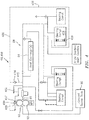
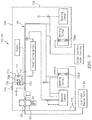
- the boost pump system 396 includes a boost pump 398 having at least one fluid inlet port 397 and at least one fluid exit port 399.
- the boost pump 398 is powered by a mechanical power source (an "MPS" such as an accessory gearbox driven directly or indirectly off an engine spool shaft) and may be configured to continuously operate; e.g., in an active state with the main supply pump 92.
- First conduits 302 are configured to tap lubricant from the main lubrication system 88 downstream of a filter 304 disposed in relative close proximity to the fluid flow exit port 95 of the main supply pump 92.
- the boost pump system 396 further includes second conduits 306 that supply lubricant to a fluid damped structure 359A utilized within a first bearing compartment 308, and third conduits 310 that supply lubricant to fluid damped structure 359B utilized within a second bearing compartment 312.
- the boost pump system 396 may include a bypass valve 314 disposed in a conduit 315 extending between the boost pump system 396 and a main lubrication system 88.
- the bypass valve 314 may be configured to open when lubricant within the boost pump system conduit 315 is at or above a predetermined pressure value; e.g., to allow some amount of the lubricant flow passing within the bypass conduit 315 back to the main lubrication system 88 and thereby control lubricant pressure within the boost pump system 396.
- the diagrammatic system shown in FIG. 3 depicts the bypass valve 314 and conduit 315 is a non-limiting diagrammatic example of how the bypass valve 314 may be disposed, and the present disclosure is not limited to this particular example.
- the boost pump system 396 may also include one or more fluid control components; e.g., metering components, shut-off valves, etc.
- the diagrammatic boost pump system 396 shown in FIG. 3 depicts a shut-off type valve 316 disposed within one of the third conduits 310.
- the present disclosure is not, however, limited to this particular embodiment. As indicated above, the present disclosure is not limited to use with any particular type of fluid damped structure.
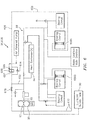
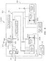
- the boost pump system 496 includes a boost pump 498 having at least one fluid inlet port 497 and at least one fluid exit port 499.
- the boost pump 498 is powered by a mechanical power source (e.g., an MPS such as an accessory gearbox and may be configured in an active state), and first conduits 402 are configured to tap lubricant from the main lubrication system 88 (e.g., as described above in the embodiment shown in FIG. 3 ).
- the boost pump system 496 further includes second conduits 406 that supply lubricant to fluid damped structure 459 utilized within a first bearing compartment 408. As can be seen in FIG.
- the boost pump system 496 may include a bypass valve 414 disposed in a conduit 415 extending between the boost pump system conduit and the main lubrication system 88 (e.g., as described above in the embodiment shown in FIG. 3 ).
- the boost pump system 496 may also include one or more fluid control components (e.g., a shut-off valve as shown in FIG. 3 ).
- the boost pump system 596 includes a boost pump 598 having at least one fluid inlet port 597 and at least one fluid exit port 599.
- the boost pump 598 is electrically powered and controlled by the Full Authority Digital Control ("FADEC") system of the gas turbine engine 20 (or other type controller).
- the boost pump system 696 includes a boost pump 698 having at least one fluid inlet port 697 and at least one fluid exit port 699.
- the boost pump 698 is pneumatically powered (and may be controlled by a FADEC or other controller).
- the present disclosure is not limited to any particular pneumatic source for powering the boost pump 698; e.g., such sources may include starter air bleed from an aircraft powered by the engine, engine bleed air, etc.
- the boost pump 598, 698 may be selectively controllable (e.g., by the FADEC or other controller) to an active state where the boost pump 598, 698 continuously operates, or in an inactive state where the boost pump 598, 698 is not operating.
- first conduits 502, 602 are configured to tap lubricant from the main lubrication system 88 (e.g., as described above in the embodiment shown in FIG.
- the boost pump 598, 698 is disposed in communication with the second conduits 506, 606 and third conduits 510, 610 to provide lubricant to the respective fluid damped structures 559A, 559B, 659A, 659B.
- the boost pump system 596, 696 may include a bypass valve 514, 614 disposed in a conduit extending around the boost pump 598, 698. In the boost pump embodiments shown in FIGS.
- the bypass valve 514, 614 is configured to selectively allow a bypass lubricant flow around the boost pump 598, 698 (e.g., when the boost pump 598, 698 is in an inactive state).
- the boost pump system 596, 696 may also include one or more fluid control components (e.g., a shut-off valve 516, 616).
- the boost pump system 796 includes a boost pump 798 having at least one fluid inlet port 797 and at least one fluid exit port 799.
- the boost pump 798 is electrically powered and controlled by the Full Authority Digital Control ("FADEC") system of the gas turbine engine (or other controller).
- the boost pump system 896 includes a boost pump 898 having at least one fluid inlet port 897 and at least one fluid exit port 899.
- the boost pump 898 is pneumatically powered (and may be controlled by a FADEC or other controller).
- the present disclosure is not limited to any particular pneumatic source for powering the boost pump 898; e.g., such sources may include starter air bleed from an aircraft powered by the engine, engine bleed air, etc.
- the boost pump 798, 898 may be selectively controllable (e.g., by the FADEC or other controller) to an active state where the boost pump 798, 898 continuously operates, or in an inactive state where the boost pump 798, 898 is not operating.
- a first conduit 702, 802 is configured to tap lubricant from the main lubrication system 88 (e.g., as described above in the embodiment shown in FIG.
- the boost pump 798, 898 is disposed in communication with the second conduits 706, 806 and third conduits 710, 810 to provide lubricant to the respective fluid damper structures 759A, 759B, 859A, 859B. As can be seen in FIGS.
- the boost pump system 996 includes a boost pump 998 having at least one fluid inlet port 997 and at least one fluid exit port 999.
- the boost pump 998 may be driven by a mechanical power source ("MPS") as described above, or may be independently powered (e.g., electrically, pneumatically, or hydraulically powered).
- a first conduit 902 is configured to tap lubricant from the main lubrication system 88 upstream of the main supply pump 92; e.g., at a point between the main supply pump 92 and the lubricant supply tank 90.
- the boost pump system 996 may include a filtering device 903 (e.g., a wash-flow screen) upstream of the boost pump 998 to catch debris or other contaminants within the fluid flow.
- a filtering device 903 e.g., a wash-flow screen
- the present disclosure is not limited to this particular filtering device, or a filtering device located in this particular location; e.g., a filtering device may be placed on a main lubricant system return line, etc.
- the fluid flow exit port 999 of the boost pump 998 is in fluid communication with second conduits 906 that supply lubricant to fluid damped structure 959 utilized within a bearing compartment 908.
- the boost pump system 996 may include a bypass valve 914 disposed in a conduit 915 extending between a second conduit section and the main lubrication system 88 (e.g., as described above in the embodiment shown in FIG. 3 ).
- the boost pump system 996 may also include one or more fluid control components (e.g., a shut-off valve as shown in FIG. 3 ).
- fluid provided to the fluid damped structure(s) by the boost pump system passes through the fluid damped structure(s) and is collected via a lubricant scavenge system and returned to the main lubrication system 88.
- Lubricant from the boost pump system is selectively combined with lubricant provided to the fluid damped structures from the main lubrication system 88; i.e., the boost pump system acts as an auxiliary source of pressurized lubricant to the fluid damped structures.
- the main supply pump 92 is configured to produce lubricant output at parameters that vary as a function of the rotational speed of a rotational component driving the main supply pump 92.
- the main supply pump 92 is mechanically driven off of the high speed spool that connects the high pressure compressor section and the high pressure turbine section. Because the main supply pump 92 is operatively linked to the high speed spool in these embodiments, the output parameters of the main supply pump 92 (e.g., lubricant fluid pressure and flow rate) vary as a function of the rotational speed of the high speed spool.
- the high speed spool is typically rotating in the range of 13,000 to 23,000 revolutions per minute ("rpms").
- rpms revolutions per minute
- a main supply pump sized to meet the engine's lubrication requirements in that operational range could theoretically meet the lubrication flow requirements of the engine.
- gas turbine engines also operate outside of the aforesaid operational range (13,000 to 23,000 rpms) under certain conditions (e.g., start-up, idle, etc.).
- the main supply pump must, therefore, be sized to satisfy the lubrication flow requirements under all anticipated engine operating conditions, or alternative means must be provided to satisfy the engine's lubrication flow requirements.
- Embodiments of the present disclosure leverage the work done by the main supply pump, using a boost pump to selectively provide a lubricant fluid flow at a pressure higher than that produced by the main supply pump to components (e.g., fluid damped structures) as necessary to meet the requirements of the aforesaid components.
- a boost pump to selectively provide a lubricant fluid flow at a pressure higher than that produced by the main supply pump to components (e.g., fluid damped structures) as necessary to meet the requirements of the aforesaid components.
- the boost pump system includes a boost pump that draws lubrication oil from the main lubrication system 88 at an elevated pressure downstream of the main supply pump 92.
- the boost pump draws lubrication oil from the main lubrication system 88 at an elevated pressure downstream of the main supply pump 92.
- the pressure of the lubrication oil is increased from P inlet to P exit (i.e., P exit > P inlet ).
- the increased pressure lubrication oil is subsequently passed to engine components (e.g., fluid damped structures disposed within bearing compartments).
- the operation of the boost pump may be terminated or the lubrication oil flow from the boost pump may be directed back to the main lubrication system and/or an oil scavenge system of the engine.
- some or all of the lubrication oil flow exiting the boost pump may be redirected by a bypass valve.
- the present disclosure also includes a method of supplying a fluid to at least one fluid damped structure disposed within a bearing compartment of a gas turbine engine using the structure described above.
- the method may include operating the main supply pump 92 of the gas turbine engine 20 to draw fluid lubricant into the MSP fluid flow inlet port 93 at a first pressure from a supply source 90, and to produce a supply fluid flow at a second pressure at the MSP fluid flow exit port 95, wherein the second pressure is greater than the first pressure, and operating the boost pump 398, 498, 598, 698, 798, 898, 998 to produce a boost supply fluid flow at a third pressure at the BP fluid flow exit port 399, 499, 599, 699, 799, 899, 999, wherein the third pressure is greater than the second pressure, and to produce the boost supply fluid flow to the at least one fluid damped structure 359A, 359B, 459, 559A, 559B, 659A, 659B, 759A, 759
- the method may also include driving the boost pump with a mechanical power source, wherein the boost pump is in an active state, and continuously producing boost supply fluid flow at the third pressure at the BP fluid flow exit port.
- the method may include driving the boost pump with an independent power source, and selectively controlling the boost pump to an active state where the boost pump continuously produces the boost supply fluid flow at the third pressure at the BP fluid flow exit port, or to an inactive state where the boost pump is not operating.
- the method may include using a bypass circuit with a bypass valve to selectively provide a fluid path for the supply fluid flow to bypass the boost pump when the boost pump is in the inactive state.
Landscapes
- Engineering & Computer Science (AREA)
- Mechanical Engineering (AREA)
- General Engineering & Computer Science (AREA)
- Rolling Contact Bearings (AREA)
Claims (15)
- Système de lubrification (88) pour un moteur à turbine à gaz (20) ayant une pluralité de composants, le système de lubrification comprenant :une source d'alimentation (90) d'un lubrifiant fluide ;une pompe d'alimentation principale (92), ayant au moins un orifice d'entrée d'écoulement de fluide (93) en communication fluidique avec la source d'alimentation (90) de lubrifiant fluide, et au moins un orifice de sortie d'écoulement de fluide (95) en communication fluidique avec la pluralité de composants de moteur ;dans lequel la pompe d'alimentation principale (92) est configurée pour recevoir un écoulement de lubrifiant fluide source depuis la source d'alimentation (90) à une première pression au niveau de l'au moins un orifice d'entrée d'écoulement de fluide (93), et configurée pour produire un écoulement de fluide d'alimentation à une deuxième pression au niveau de l'au moins un orifice de sortie d'écoulement de fluide (95), dans lequel la deuxième pression est supérieure à la première pression ; etun système de pompe de suralimentation (96 ; 396 ; 496 ; 596 ; 696 ; 796 ; 896) comportant une pompe de suralimentation (98 ; 398 ; 498 ; 598 ; 698 ; 798 ; 898), la pompe de suralimentation (98...898) comportant au moins un orifice d'entrée d'écoulement de fluide (97 ; 397 ; 497 ; 597 ; 697 ; 797 ; 897) en communication fluidique sélective avec l'au moins un orifice de sortie d'écoulement de fluide (95), et au moins un orifice de sortie d'écoulement de fluide (99 ; 399 ; 499 ; 599 ; 699 ; 799 ; 899) en communication fluidique sélective avec au moins l'un de la pluralité de composants de moteur ; etdans lequel la pompe de suralimentation (98...898) est configurée pour produire un écoulement de fluide d'alimentation de suralimentation à une troisième pression au niveau de l'au moins un orifice de sortie d'écoulement de fluide (99...899) de la pompe de suralimentation (98...898), dans lequel la troisième pression est supérieure à la deuxième pression ; caractérisé en ce quele système de pompe de suralimentation (96...896) est configuré de sorte que la pompe de suralimentation (98...898) reçoit sélectivement au moins une partie de l'écoulement de fluide d'alimentation depuis la pompe d'alimentation principale (92) au niveau de l'au moins un orifice d'entrée d'écoulement de fluide (97...897) de la pompe de suralimentation (98...898) à une pression et à un débit établis par la pompe d'alimentation principale (92) ; etl'écoulement de fluide d'alimentation de suralimentation depuis le système de pompe de suralimentation (96...896) est configuré pour être combiné sélectivement avec l'écoulement de fluide d'alimentation depuis la pompe d'alimentation principale (92) du système de lubrification (88) fourni à au moins l'un de la pluralité de composants de moteur.
- Système de lubrification selon la revendication 1, dans lequel la pompe de suralimentation (98 ; 398 ; 498) est entraînée par une source d'énergie mécanique (MPS).
- Moteur à turbine à gaz (20), comprenant :au moins un arbre (40, 50, 61) ;au moins un compartiment de palier (308 ; 408) disposé pour supporter l'arbre (40, 50, 61), le compartiment de palier (308 ; 408) comportant au moins un palier (63) et au moins une structure amortie par un fluide (359A, 359B ; 459 ; 559A, 559B ; 659A, 659B ; 759A, 759B ; 859A, 859B) ; etle système de lubrification (88) selon la revendication 1, dans lequel :la pluralité de composants de moteur comprend l'au moins un compartiment de palier (308 ; 408) ; etl'au moins un de la pluralité de composants de moteur comprend l'au moins une structure amortie par un fluide (359A...859B) de l'au moins un compartiment de palier (308 ; 408).
- Moteur à turbine à gaz selon la revendication 3, dans lequel la pompe de suralimentation (98 ; 398 ; 498) est entraînée par une source d'énergie mécanique (MPS) directement ou indirectement en communication avec l'au moins un arbre (40, 50, 61).
- Système de lubrification selon la revendication 2 ou moteur à turbine à gaz selon la revendication 4, dans lesquels la pompe de suralimentation (98 ; 398 ; 498) est configurée pour fonctionner en continu avec la pompe d'alimentation principale (92).
- Système de lubrification ou moteur à turbine à gaz selon la revendication 5, dans lesquels le système de pompe de suralimentation (96...896) comporte une soupape de dérivation (314 ; 414) et est configuré pour diriger sélectivement au moins une partie d'écoulement de fluide d'alimentation de suralimentation à travers la soupape de dérivation (314 ; 414) et hors du système de pompe de suralimentation (96...896) à une position en amont de l'au moins un de la pluralité de composants de moteur.
- Système de lubrification selon la revendication 1 ou moteur à turbine à gaz selon la revendication 3, dans lesquels la pompe de suralimentation (598 ; 698 ; 798 ; 898) est entraînée par une source d'alimentation indépendante, et dans lequel la pompe de suralimentation (598 ; 698 ; 798 ; 898) peut être commandée sélectivement jusqu'à un état actif où la pompe de suralimentation (598 ; 698 ; 798 ; 898) produit en continu l'écoulement de fluide d'alimentation de suralimentation à la troisième pression au niveau de l'au moins un orifice de sortie d'écoulement de fluide (599 ; 699 ; 799 ; 899) de la pompe de suralimentation (598 ; 698 ; 798 ; 898), ou jusqu'à un état inactif où la pompe de suralimentation (598 ; 698 ; 798 ; 898) ne fonctionne pas.
- Système de lubrification ou moteur à turbine à gaz selon la revendication 7, dans lesquels la pompe de suralimentation (598...898) est au moins l'une parmi une pompe à commande pneumatique, électrique ou hydraulique.
- Système de lubrification ou moteur à turbine à gaz selon la revendication 7 ou 8, dans lesquels le système de pompe de suralimentation (596 ; 696 ; 796 ; 896) comporte un circuit de dérivation comportant une soupape de dérivation (514 ; 614 ; 714), lequel circuit de dérivation est configuré pour fournir sélectivement un trajet de fluide pour que l'écoulement de fluide d'alimentation contourne la pompe de suralimentation lorsque la pompe de suralimentation (598...898) est dans l'état inactif.
- Moteur à turbine à gaz selon l'une quelconque des revendications 3 à 9, dans lequel l'au moins une structure amortie par un fluide (359A...859B) est disposée à l'intérieur du compartiment de palier (308 ; 408) et configurée pour permettre un mouvement radial de l'au moins un palier (63) à l'intérieur du compartiment de palier (308 ; 408).
- Procédé pour fournir un fluide à au moins une structure amortie par un fluide disposée à l'intérieur d'un compartiment de palier (308 ; 408) d'un moteur à turbine à gaz (20), dans lequel le moteur à turbine à gaz (20) comporte un arbre (40 ; 50 ; 61) et le compartiment de palier (308 ; 408) est disposé pour supporter l'arbre (40 ; 50 ; 61), le procédé comprenant :le fonctionnement d'une pompe d'alimentation principale (« MSP ») (92) du moteur à turbine à gaz (20), la pompe d'alimentation principale (92) comportant au moins un orifice d'entrée d'écoulement de fluide MSP (93) et au moins un orifice de sortie d'écoulement de fluide MSP (95), et l'aspiration d'un lubrifiant fluide dans l'au moins un orifice d'entrée d'écoulement de fluide MSP (93) à une première pression depuis une source d'alimentation (90), et pour produire un écoulement de fluide d'alimentation à une deuxième pression au niveau de l'au moins un orifice de sortie d'écoulement de fluide MSP (95), dans lequel la deuxième pression est supérieure à la première pression ;le fonctionnement d'une pompe de suralimentation (« BP ») (98 ; 398 ; 498 ; 598 ; 698 ; 798 ; 898), la pompe de suralimentation ayant au moins un orifice d'entrée d'écoulement de fluide BP (97 ; 397 ; 497 ; 597 ; 697 ; 797 ; 897) en communication fluidique sélective avec l'au moins un orifice de sortie d'écoulement de fluide MSP (95) et configuré pour recevoir au moins une partie de l'écoulement de fluide d'alimentation depuis la MSP (92) à une pression et à un débit établis par la MSP (92) et au moins un orifice de sortie d'écoulement de fluide BP (99...899) en communication fluidique avec l'au moins une structure amortie par un fluide (359A...859B) ;dans lequel la pompe de suralimentation est mise en fonctionnement pour produire un écoulement de fluide d'alimentation de suralimentation à une troisième pression au niveau de l'au moins un orifice de sortie d'écoulement de fluide BP (99 ; 399 ; 499 ; 599 ; 699 ; 799 ; 899), dans lequel la troisième pression est supérieure à la deuxième pression, et pour produire l'écoulement de fluide d'alimentation de suralimentation vers l'au moins une structure amortie par un fluide (359A...859B) ; etdans lequel l'écoulement de fluide d'alimentation de suralimentation depuis la BP (98...998) est combiné sélectivement avec l'écoulement de fluide d'alimentation depuis la MSP (92) fourni à l'au moins une structure amortie par un fluide (359A...859B).
- Procédé selon la revendication 11, dans lequel la pompe de suralimentation (98 ; 398 ; 498) est entraînée par une source d'énergie mécanique (MPS) directement ou indirectement en communication avec l'arbre (40 ; 50 ; 61), et la pompe de suralimentation (98 ; 398 ; 498) est dans un état actif, dans lequel la pompe de suralimentation (98 ; 398 ; 498) produit en continu l'écoulement de fluide d'alimentation de suralimentation à la troisième pression au niveau de l'au moins un orifice de sortie d'écoulement de fluide (99 ; 399 ; 499) de la pompe de suralimentation (98 ; 398 ; 498).
- Procédé selon la revendication 11, dans lequel la pompe de suralimentation (598 ; 698 ; 798 ; 898) est entraînée par une source d'alimentation indépendante ; et
la commande sélective de la pompe de suralimentation (598...898) jusqu'à un état actif où la pompe de suralimentation (598...898) produit en continu l'écoulement de fluide d'alimentation de suralimentation à la troisième pression au niveau de l'au moins un orifice de sortie d'écoulement de fluide (599 ; 699 ; 799 ; 899) de la pompe de suralimentation (598... 898), ou jusqu'à un état inactif où la pompe de suralimentation (598...898) ne fonctionne pas. - Procédé selon la revendication 13, dans lequel la pompe de suralimentation (598...898) est au moins l'une parmi une pompe à commande pneumatique, électrique ou hydraulique.
- Procédé selon la revendication 13 ou 14, comprenant en outre l'utilisation d'un circuit de dérivation ayant une soupape de dérivation (514 ; 614 ; 714) pour fournir sélectivement un trajet de fluide pour que l'écoulement de fluide d'alimentation contourne la pompe de suralimentation (598...898) lorsque la pompe de suralimentation (598...898) est dans l'état inactif.
Applications Claiming Priority (1)
| Application Number | Priority Date | Filing Date | Title |
|---|---|---|---|
| US15/475,736 US10711642B2 (en) | 2017-03-31 | 2017-03-31 | Gas turbine engine lubrication system and apparatus with boost pump system |
Publications (2)
| Publication Number | Publication Date |
|---|---|
| EP3382163A1 EP3382163A1 (fr) | 2018-10-03 |
| EP3382163B1 true EP3382163B1 (fr) | 2020-07-08 |
Family
ID=61899077
Family Applications (1)
| Application Number | Title | Priority Date | Filing Date |
|---|---|---|---|
| EP18165527.5A Active EP3382163B1 (fr) | 2017-03-31 | 2018-04-03 | Système de lubrification de moteur à turbine à gaz, moteur à turbine à gaz comportant un système de pompe de suralimentation et procédé correspondant |
Country Status (2)
| Country | Link |
|---|---|
| US (1) | US10711642B2 (fr) |
| EP (1) | EP3382163B1 (fr) |
Families Citing this family (15)
| Publication number | Priority date | Publication date | Assignee | Title |
|---|---|---|---|---|
| US20180340471A1 (en) * | 2015-11-03 | 2018-11-29 | Eaton Corporation | Pump bearing flow control |
| US10458278B2 (en) * | 2016-11-04 | 2019-10-29 | United Technologies Corporation | Apparatus and method for providing fluid to a bearing damper |
| US10830139B2 (en) | 2017-02-06 | 2020-11-10 | Raytheon Technologies Corporation | Fitting for multiwall tube |
| US10465828B2 (en) | 2017-02-06 | 2019-11-05 | United Technologies Corporation | Tube fitting |
| US10393303B2 (en) | 2017-02-06 | 2019-08-27 | United Technologies Corporation | Threaded fitting for tube |
| US10385710B2 (en) | 2017-02-06 | 2019-08-20 | United Technologies Corporation | Multiwall tube and fitting for bearing oil supply |
| US10711642B2 (en) * | 2017-03-31 | 2020-07-14 | Raytheon Technologies Corporation | Gas turbine engine lubrication system and apparatus with boost pump system |
| US10711644B2 (en) * | 2017-04-24 | 2020-07-14 | Raytheon Technologies Corporation | Method and system to ensure full oil tubes after gas turbine engine shutdown |
| US11162419B2 (en) * | 2018-02-12 | 2021-11-02 | General Electric Company | Method and structure for operating engine with bowed rotor condition |
| US11428163B2 (en) | 2018-12-18 | 2022-08-30 | Raytheon Technologies Corporation | Two tier lubrication system |
| US11236637B2 (en) * | 2018-12-21 | 2022-02-01 | Raytheon Technologies Corporation | Auxiliary lubrication system with flow management valve |
| EP4635853A3 (fr) * | 2021-06-11 | 2025-11-05 | RTX Corporation | Système de circulation d'huile pour moteur électrique hybride |
| US11732646B2 (en) * | 2021-07-06 | 2023-08-22 | Pratt & Whitney Canada Corp. | Lubrication system for a turbine engine |
| US11719128B2 (en) * | 2021-07-06 | 2023-08-08 | Pratt & Whitney Canada Corp. | Lubrication system with anti-priming feature |
| US20250109709A1 (en) * | 2023-10-03 | 2025-04-03 | Rtx Corporation | Electronically driven lubrication system on gas turbine engines |
Family Cites Families (40)
| Publication number | Priority date | Publication date | Assignee | Title |
|---|---|---|---|---|
| NL132683C (fr) * | 1966-10-13 | |||
| CH622061A5 (fr) | 1977-06-24 | 1981-03-13 | Bbc Brown Boveri & Cie | |
| JPS62107206A (ja) | 1985-11-05 | 1987-05-18 | Hitachi Ltd | タ−ビン発電機軸のジヤツキアツプ装置 |
| US4947639A (en) | 1988-05-12 | 1990-08-14 | United Technologies Corporation | Apparatus and method for supporting a rotating shaft in a rotary machine |
| US4983051A (en) | 1988-05-12 | 1991-01-08 | United Technologies Corporation | Apparatus for supporting a rotating shaft in a rotary machine |
| US5110257A (en) * | 1988-05-12 | 1992-05-05 | United Technologies Corporation | Apparatus for supporting a rotating shaft in a rotary machine |
| US4926641A (en) * | 1989-01-11 | 1990-05-22 | Keller Robert A | Turbocharger lubrication system |
| US5911678A (en) | 1997-07-11 | 1999-06-15 | Rolls-Royce Plc | Gas turbine engine starting |
| GB2388634A (en) * | 2002-05-15 | 2003-11-19 | Dana Automotive Ltd | Engine lubrication system having dual/auxiliary pump operation |
| GB0318400D0 (en) * | 2003-08-06 | 2003-09-10 | Rolls Royce Plc | A fluid system |
| US7692347B2 (en) | 2004-10-12 | 2010-04-06 | Nissan Motor Co., Ltd. | Vibration damping for a rotating shaft |
| US8490752B2 (en) * | 2006-10-24 | 2013-07-23 | United Technologies Corporation | Accurate fluid volume measurement for thermally expanding fluids |
| US8020665B2 (en) * | 2006-11-22 | 2011-09-20 | United Technologies Corporation | Lubrication system with extended emergency operability |
| DE602007010805D1 (de) * | 2007-12-21 | 2011-01-05 | Techspace Aero Sa | Rückführventil in einem Flugzeugmotor |
| US8511055B2 (en) | 2009-05-22 | 2013-08-20 | United Technologies Corporation | Apparatus and method for providing damper liquid in a gas turbine |
| US8230974B2 (en) | 2009-05-22 | 2012-07-31 | United Technologies Corporation | Windmill and zero gravity lubrication system for a gas turbine engine |
| US8051869B2 (en) * | 2009-05-22 | 2011-11-08 | United Technologies Corporation | Gravity operated valve |
| US8381878B2 (en) * | 2009-11-12 | 2013-02-26 | United Technologies Corporation | Oil capture and bypass system |
| US20120241258A1 (en) * | 2011-03-23 | 2012-09-27 | Pradip Radhakrishnan Subramaniam | Lubricant supply system and method for controlling gearbox lubrication |
| US8833086B2 (en) * | 2012-05-31 | 2014-09-16 | United Technologies Corporation | Lubrication arrangement for a gas turbine engine gear assembly |
| US20140090930A1 (en) * | 2012-09-28 | 2014-04-03 | United Technologies Corporation | Multiple reservoir lubrication system |
| US10107197B2 (en) * | 2012-11-30 | 2018-10-23 | United Technologies Corporation | Lubrication system for gas turbine engines |
| WO2014133836A1 (fr) * | 2013-02-28 | 2014-09-04 | United Technologies Corporation | Filtre à débris autonettoyant pour système d'engrenage d'entraînement de ventilateur |
| EP3044438B1 (fr) * | 2013-09-13 | 2018-07-04 | United Technologies Corporation | Systeme de surveillance de pompe auxiliaire d'un systeme de lubrification d'engrenage pour turbosoufflante |
| EP3090147B1 (fr) * | 2013-12-05 | 2021-04-28 | Raytheon Technologies Corporation | Système de contrôle de pompe auxiliaire et procédé de contrôle |
| US10066507B1 (en) * | 2015-02-10 | 2018-09-04 | United Technologies Corporation | Turbine engine lubrication system with wash flow filter |
| US20160245117A1 (en) * | 2015-02-24 | 2016-08-25 | United Technologies Corporation | In-line deaerator device for windmill-auxiliary oil system for fan drive gear system |
| US9494048B1 (en) | 2015-05-12 | 2016-11-15 | United Technologies Corporation | Active system for bearing oil damper supply and vibration control |
| US10145276B2 (en) * | 2015-06-23 | 2018-12-04 | United Technologies Corporation | Lubricant valve monitoring method and assembly |
| US10041489B2 (en) * | 2015-10-22 | 2018-08-07 | United Technologies Corporation | Auxiliary pump and gas turbine engine oil circuit monitoring system |
| US10267233B2 (en) * | 2015-10-23 | 2019-04-23 | United Technologies Corporation | Method and apparatus for monitoring lubrication pump operation during windmilling |
| US10161408B2 (en) * | 2015-10-29 | 2018-12-25 | United Technologies Corporation | Manhattan dual FDGS aux pump design |
| US20170362959A1 (en) * | 2016-06-20 | 2017-12-21 | United Technologies Corporation | Lubrication system with multiple lubrication circuits |
| US10544717B2 (en) * | 2016-09-07 | 2020-01-28 | Pratt & Whitney Canada Corp. | Shared oil system arrangement for an engine component and a generator |
| US10513949B2 (en) * | 2016-09-09 | 2019-12-24 | United Technologies Corporation | Auxiliary journal oil supply system |
| US10458278B2 (en) * | 2016-11-04 | 2019-10-29 | United Technologies Corporation | Apparatus and method for providing fluid to a bearing damper |
| JP6746511B2 (ja) * | 2017-01-31 | 2020-08-26 | 株式会社東芝 | 蒸気タービン弁駆動装置 |
| US10711642B2 (en) * | 2017-03-31 | 2020-07-14 | Raytheon Technologies Corporation | Gas turbine engine lubrication system and apparatus with boost pump system |
| US10711644B2 (en) * | 2017-04-24 | 2020-07-14 | Raytheon Technologies Corporation | Method and system to ensure full oil tubes after gas turbine engine shutdown |
| US10851941B2 (en) * | 2017-12-04 | 2020-12-01 | Rolls-Royce Corporation | Lubrication and scavenge system |
-
2017
- 2017-03-31 US US15/475,736 patent/US10711642B2/en active Active
-
2018
- 2018-04-03 EP EP18165527.5A patent/EP3382163B1/fr active Active
Non-Patent Citations (1)
| Title |
|---|
| None * |
Also Published As
| Publication number | Publication date |
|---|---|
| US20180283211A1 (en) | 2018-10-04 |
| US10711642B2 (en) | 2020-07-14 |
| EP3382163A1 (fr) | 2018-10-03 |
Similar Documents
| Publication | Publication Date | Title |
|---|---|---|
| EP3382163B1 (fr) | Système de lubrification de moteur à turbine à gaz, moteur à turbine à gaz comportant un système de pompe de suralimentation et procédé correspondant | |
| US11846237B2 (en) | Gas turbine engine with intercooled cooling air and dual towershaft accessory gearbox | |
| EP3354881B1 (fr) | Boîte d'engrenages d'accessoires de moteur à turbine à gaz à deux arbres d'entraînement et ensemble générateur de démarreur | |
| EP2855882B1 (fr) | Dispositif de lubrification pour un engrenage de turbine à gaz | |
| US9062611B2 (en) | Split accessory drive system | |
| EP3336334B1 (fr) | Transmission à entraînement par traction pour boîte de vitesses d'accessoire de moteur à turbine à gaz | |
| EP2971662B1 (fr) | Circulation d'un lubrifiant à travers un composant de moteur de turbine comportant des pompes parallèles | |
| EP3020953B1 (fr) | Moteur à turbine à gaz | |
| EP3388650B1 (fr) | Entraînement de boîtier d'accessoire à arbre de transmission haute et basse pression | |
| EP3699413B1 (fr) | Filtres de tube radial de collecteur de système d'engrenage d'entraînement de ventilateur | |
| WO2015060912A2 (fr) | Pompe de moulinet à deux directions pour turboréacteur à engrenages | |
| EP4215737B1 (fr) | Extraction de puissance à double bobine avec boîte de vitesses à superposition | |
| WO2015047885A1 (fr) | Commande d'écoulement de lubrifiant dans une boîte d'engrenages épicycloîdaux | |
| EP2959129A2 (fr) | Étage auxiliaire de pompe d'alimentation en lubrifiant formé d'un seul tenant avec un étage principal de pompe à lubrifiant | |
| US20180202367A1 (en) | Gas turbine engine dual towershaft accessory gearbox assembly with a transmission | |
| US10590852B2 (en) | Gas turbine engine dual towershaft accessory gearbox assembly with a transmission | |
| US20250361834A1 (en) | Turbine engine and lubricant reservoir for planetary gearbox | |
| EP4517074A1 (fr) | Système de lubrification d'engrenage d'entraînement de ventilateur planté à entraînement par arbre de tour | |
| US12553380B2 (en) | Constant speed accessory gearbox for turbine engine |
Legal Events
| Date | Code | Title | Description |
|---|---|---|---|
| PUAI | Public reference made under article 153(3) epc to a published international application that has entered the european phase |
Free format text: ORIGINAL CODE: 0009012 |
|
| STAA | Information on the status of an ep patent application or granted ep patent |
Free format text: STATUS: THE APPLICATION HAS BEEN PUBLISHED |
|
| AK | Designated contracting states |
Kind code of ref document: A1 Designated state(s): AL AT BE BG CH CY CZ DE DK EE ES FI FR GB GR HR HU IE IS IT LI LT LU LV MC MK MT NL NO PL PT RO RS SE SI SK SM TR |
|
| AX | Request for extension of the european patent |
Extension state: BA ME |
|
| STAA | Information on the status of an ep patent application or granted ep patent |
Free format text: STATUS: REQUEST FOR EXAMINATION WAS MADE |
|
| 17P | Request for examination filed |
Effective date: 20190402 |
|
| RBV | Designated contracting states (corrected) |
Designated state(s): AL AT BE BG CH CY CZ DE DK EE ES FI FR GB GR HR HU IE IS IT LI LT LU LV MC MK MT NL NO PL PT RO RS SE SI SK SM TR |
|
| GRAP | Despatch of communication of intention to grant a patent |
Free format text: ORIGINAL CODE: EPIDOSNIGR1 |
|
| STAA | Information on the status of an ep patent application or granted ep patent |
Free format text: STATUS: GRANT OF PATENT IS INTENDED |
|
| INTG | Intention to grant announced |
Effective date: 20200128 |
|
| GRAS | Grant fee paid |
Free format text: ORIGINAL CODE: EPIDOSNIGR3 |
|
| GRAA | (expected) grant |
Free format text: ORIGINAL CODE: 0009210 |
|
| STAA | Information on the status of an ep patent application or granted ep patent |
Free format text: STATUS: THE PATENT HAS BEEN GRANTED |
|
| AK | Designated contracting states |
Kind code of ref document: B1 Designated state(s): AL AT BE BG CH CY CZ DE DK EE ES FI FR GB GR HR HU IE IS IT LI LT LU LV MC MK MT NL NO PL PT RO RS SE SI SK SM TR |
|
| REG | Reference to a national code |
Ref country code: CH Ref legal event code: EP Ref country code: AT Ref legal event code: REF Ref document number: 1288676 Country of ref document: AT Kind code of ref document: T Effective date: 20200715 |
|
| REG | Reference to a national code |
Ref country code: DE Ref legal event code: R096 Ref document number: 602018005785 Country of ref document: DE |
|
| REG | Reference to a national code |
Ref country code: IE Ref legal event code: FG4D |
|
| REG | Reference to a national code |
Ref country code: LT Ref legal event code: MG4D |
|
| REG | Reference to a national code |
Ref country code: AT Ref legal event code: MK05 Ref document number: 1288676 Country of ref document: AT Kind code of ref document: T Effective date: 20200708 |
|
| REG | Reference to a national code |
Ref country code: NL Ref legal event code: MP Effective date: 20200708 |
|
| PG25 | Lapsed in a contracting state [announced via postgrant information from national office to epo] |
Ref country code: PT Free format text: LAPSE BECAUSE OF FAILURE TO SUBMIT A TRANSLATION OF THE DESCRIPTION OR TO PAY THE FEE WITHIN THE PRESCRIBED TIME-LIMIT Effective date: 20201109 Ref country code: LT Free format text: LAPSE BECAUSE OF FAILURE TO SUBMIT A TRANSLATION OF THE DESCRIPTION OR TO PAY THE FEE WITHIN THE PRESCRIBED TIME-LIMIT Effective date: 20200708 Ref country code: HR Free format text: LAPSE BECAUSE OF FAILURE TO SUBMIT A TRANSLATION OF THE DESCRIPTION OR TO PAY THE FEE WITHIN THE PRESCRIBED TIME-LIMIT Effective date: 20200708 Ref country code: AT Free format text: LAPSE BECAUSE OF FAILURE TO SUBMIT A TRANSLATION OF THE DESCRIPTION OR TO PAY THE FEE WITHIN THE PRESCRIBED TIME-LIMIT Effective date: 20200708 Ref country code: NO Free format text: LAPSE BECAUSE OF FAILURE TO SUBMIT A TRANSLATION OF THE DESCRIPTION OR TO PAY THE FEE WITHIN THE PRESCRIBED TIME-LIMIT Effective date: 20201008 Ref country code: GR Free format text: LAPSE BECAUSE OF FAILURE TO SUBMIT A TRANSLATION OF THE DESCRIPTION OR TO PAY THE FEE WITHIN THE PRESCRIBED TIME-LIMIT Effective date: 20201009 Ref country code: ES Free format text: LAPSE BECAUSE OF FAILURE TO SUBMIT A TRANSLATION OF THE DESCRIPTION OR TO PAY THE FEE WITHIN THE PRESCRIBED TIME-LIMIT Effective date: 20200708 Ref country code: BG Free format text: LAPSE BECAUSE OF FAILURE TO SUBMIT A TRANSLATION OF THE DESCRIPTION OR TO PAY THE FEE WITHIN THE PRESCRIBED TIME-LIMIT Effective date: 20201008 Ref country code: FI Free format text: LAPSE BECAUSE OF FAILURE TO SUBMIT A TRANSLATION OF THE DESCRIPTION OR TO PAY THE FEE WITHIN THE PRESCRIBED TIME-LIMIT Effective date: 20200708 Ref country code: SE Free format text: LAPSE BECAUSE OF FAILURE TO SUBMIT A TRANSLATION OF THE DESCRIPTION OR TO PAY THE FEE WITHIN THE PRESCRIBED TIME-LIMIT Effective date: 20200708 |
|
| PG25 | Lapsed in a contracting state [announced via postgrant information from national office to epo] |
Ref country code: LV Free format text: LAPSE BECAUSE OF FAILURE TO SUBMIT A TRANSLATION OF THE DESCRIPTION OR TO PAY THE FEE WITHIN THE PRESCRIBED TIME-LIMIT Effective date: 20200708 Ref country code: PL Free format text: LAPSE BECAUSE OF FAILURE TO SUBMIT A TRANSLATION OF THE DESCRIPTION OR TO PAY THE FEE WITHIN THE PRESCRIBED TIME-LIMIT Effective date: 20200708 Ref country code: RS Free format text: LAPSE BECAUSE OF FAILURE TO SUBMIT A TRANSLATION OF THE DESCRIPTION OR TO PAY THE FEE WITHIN THE PRESCRIBED TIME-LIMIT Effective date: 20200708 Ref country code: IS Free format text: LAPSE BECAUSE OF FAILURE TO SUBMIT A TRANSLATION OF THE DESCRIPTION OR TO PAY THE FEE WITHIN THE PRESCRIBED TIME-LIMIT Effective date: 20201108 |
|
| RAP2 | Party data changed (patent owner data changed or rights of a patent transferred) |
Owner name: RAYTHEON TECHNOLOGIES CORPORATION |
|
| PG25 | Lapsed in a contracting state [announced via postgrant information from national office to epo] |
Ref country code: NL Free format text: LAPSE BECAUSE OF FAILURE TO SUBMIT A TRANSLATION OF THE DESCRIPTION OR TO PAY THE FEE WITHIN THE PRESCRIBED TIME-LIMIT Effective date: 20200708 |
|
| REG | Reference to a national code |
Ref country code: DE Ref legal event code: R097 Ref document number: 602018005785 Country of ref document: DE |
|
| PG25 | Lapsed in a contracting state [announced via postgrant information from national office to epo] |
Ref country code: RO Free format text: LAPSE BECAUSE OF FAILURE TO SUBMIT A TRANSLATION OF THE DESCRIPTION OR TO PAY THE FEE WITHIN THE PRESCRIBED TIME-LIMIT Effective date: 20200708 Ref country code: CZ Free format text: LAPSE BECAUSE OF FAILURE TO SUBMIT A TRANSLATION OF THE DESCRIPTION OR TO PAY THE FEE WITHIN THE PRESCRIBED TIME-LIMIT Effective date: 20200708 Ref country code: DK Free format text: LAPSE BECAUSE OF FAILURE TO SUBMIT A TRANSLATION OF THE DESCRIPTION OR TO PAY THE FEE WITHIN THE PRESCRIBED TIME-LIMIT Effective date: 20200708 Ref country code: EE Free format text: LAPSE BECAUSE OF FAILURE TO SUBMIT A TRANSLATION OF THE DESCRIPTION OR TO PAY THE FEE WITHIN THE PRESCRIBED TIME-LIMIT Effective date: 20200708 Ref country code: SM Free format text: LAPSE BECAUSE OF FAILURE TO SUBMIT A TRANSLATION OF THE DESCRIPTION OR TO PAY THE FEE WITHIN THE PRESCRIBED TIME-LIMIT Effective date: 20200708 Ref country code: IT Free format text: LAPSE BECAUSE OF FAILURE TO SUBMIT A TRANSLATION OF THE DESCRIPTION OR TO PAY THE FEE WITHIN THE PRESCRIBED TIME-LIMIT Effective date: 20200708 |
|
| PLBE | No opposition filed within time limit |
Free format text: ORIGINAL CODE: 0009261 |
|
| STAA | Information on the status of an ep patent application or granted ep patent |
Free format text: STATUS: NO OPPOSITION FILED WITHIN TIME LIMIT |
|
| PG25 | Lapsed in a contracting state [announced via postgrant information from national office to epo] |
Ref country code: AL Free format text: LAPSE BECAUSE OF FAILURE TO SUBMIT A TRANSLATION OF THE DESCRIPTION OR TO PAY THE FEE WITHIN THE PRESCRIBED TIME-LIMIT Effective date: 20200708 |
|
| 26N | No opposition filed |
Effective date: 20210409 |
|
| PG25 | Lapsed in a contracting state [announced via postgrant information from national office to epo] |
Ref country code: SK Free format text: LAPSE BECAUSE OF FAILURE TO SUBMIT A TRANSLATION OF THE DESCRIPTION OR TO PAY THE FEE WITHIN THE PRESCRIBED TIME-LIMIT Effective date: 20200708 |
|
| PG25 | Lapsed in a contracting state [announced via postgrant information from national office to epo] |
Ref country code: SI Free format text: LAPSE BECAUSE OF FAILURE TO SUBMIT A TRANSLATION OF THE DESCRIPTION OR TO PAY THE FEE WITHIN THE PRESCRIBED TIME-LIMIT Effective date: 20200708 |
|
| PG25 | Lapsed in a contracting state [announced via postgrant information from national office to epo] |
Ref country code: MC Free format text: LAPSE BECAUSE OF FAILURE TO SUBMIT A TRANSLATION OF THE DESCRIPTION OR TO PAY THE FEE WITHIN THE PRESCRIBED TIME-LIMIT Effective date: 20200708 |
|
| PG25 | Lapsed in a contracting state [announced via postgrant information from national office to epo] |
Ref country code: LU Free format text: LAPSE BECAUSE OF NON-PAYMENT OF DUE FEES Effective date: 20210403 |
|
| REG | Reference to a national code |
Ref country code: BE Ref legal event code: MM Effective date: 20210430 |
|
| PG25 | Lapsed in a contracting state [announced via postgrant information from national office to epo] |
Ref country code: CH Free format text: LAPSE BECAUSE OF NON-PAYMENT OF DUE FEES Effective date: 20210430 Ref country code: LI Free format text: LAPSE BECAUSE OF NON-PAYMENT OF DUE FEES Effective date: 20210430 |
|
| PG25 | Lapsed in a contracting state [announced via postgrant information from national office to epo] |
Ref country code: IE Free format text: LAPSE BECAUSE OF NON-PAYMENT OF DUE FEES Effective date: 20210403 |
|
| PG25 | Lapsed in a contracting state [announced via postgrant information from national office to epo] |
Ref country code: IS Free format text: LAPSE BECAUSE OF FAILURE TO SUBMIT A TRANSLATION OF THE DESCRIPTION OR TO PAY THE FEE WITHIN THE PRESCRIBED TIME-LIMIT Effective date: 20201108 |
|
| PG25 | Lapsed in a contracting state [announced via postgrant information from national office to epo] |
Ref country code: BE Free format text: LAPSE BECAUSE OF NON-PAYMENT OF DUE FEES Effective date: 20210430 |
|
| P01 | Opt-out of the competence of the unified patent court (upc) registered |
Effective date: 20230521 |
|
| PG25 | Lapsed in a contracting state [announced via postgrant information from national office to epo] |
Ref country code: CY Free format text: LAPSE BECAUSE OF FAILURE TO SUBMIT A TRANSLATION OF THE DESCRIPTION OR TO PAY THE FEE WITHIN THE PRESCRIBED TIME-LIMIT Effective date: 20200708 |
|
| PG25 | Lapsed in a contracting state [announced via postgrant information from national office to epo] |
Ref country code: HU Free format text: LAPSE BECAUSE OF FAILURE TO SUBMIT A TRANSLATION OF THE DESCRIPTION OR TO PAY THE FEE WITHIN THE PRESCRIBED TIME-LIMIT; INVALID AB INITIO Effective date: 20180403 |
|
| PG25 | Lapsed in a contracting state [announced via postgrant information from national office to epo] |
Ref country code: MK Free format text: LAPSE BECAUSE OF FAILURE TO SUBMIT A TRANSLATION OF THE DESCRIPTION OR TO PAY THE FEE WITHIN THE PRESCRIBED TIME-LIMIT Effective date: 20200708 |
|
| PG25 | Lapsed in a contracting state [announced via postgrant information from national office to epo] |
Ref country code: MT Free format text: LAPSE BECAUSE OF FAILURE TO SUBMIT A TRANSLATION OF THE DESCRIPTION OR TO PAY THE FEE WITHIN THE PRESCRIBED TIME-LIMIT Effective date: 20200708 |
|
| PGFP | Annual fee paid to national office [announced via postgrant information from national office to epo] |
Ref country code: DE Payment date: 20250319 Year of fee payment: 8 |
|
| REG | Reference to a national code |
Ref country code: DE Ref legal event code: R081 Ref document number: 602018005785 Country of ref document: DE Owner name: RTX CORPORATION (N.D.GES.D. STAATES DELAWARE),, US Free format text: FORMER OWNER: UNITED TECHNOLOGIES CORPORATION, FARMINGTON, CONN., US |
|
| PG25 | Lapsed in a contracting state [announced via postgrant information from national office to epo] |
Ref country code: TR Free format text: LAPSE BECAUSE OF FAILURE TO SUBMIT A TRANSLATION OF THE DESCRIPTION OR TO PAY THE FEE WITHIN THE PRESCRIBED TIME-LIMIT Effective date: 20200708 |
|
| PGFP | Annual fee paid to national office [announced via postgrant information from national office to epo] |
Ref country code: GB Payment date: 20260319 Year of fee payment: 9 |
|
| PGFP | Annual fee paid to national office [announced via postgrant information from national office to epo] |
Ref country code: FR Payment date: 20260319 Year of fee payment: 9 |