EP3382200B1 - Ensemble grue à plate-forme pour une éolienne - Google Patents
Ensemble grue à plate-forme pour une éolienne Download PDFInfo
- Publication number
- EP3382200B1 EP3382200B1 EP17382156.2A EP17382156A EP3382200B1 EP 3382200 B1 EP3382200 B1 EP 3382200B1 EP 17382156 A EP17382156 A EP 17382156A EP 3382200 B1 EP3382200 B1 EP 3382200B1
- Authority
- EP
- European Patent Office
- Prior art keywords
- hub
- wind turbine
- hoist
- articulating arm
- arm
- Prior art date
- Legal status (The legal status is an assumption and is not a legal conclusion. Google has not performed a legal analysis and makes no representation as to the accuracy of the status listed.)
- Active
Links
Images






Classifications
-
- F—MECHANICAL ENGINEERING; LIGHTING; HEATING; WEAPONS; BLASTING
- F03—MACHINES OR ENGINES FOR LIQUIDS; WIND, SPRING, OR WEIGHT MOTORS; PRODUCING MECHANICAL POWER OR A REACTIVE PROPULSIVE THRUST, NOT OTHERWISE PROVIDED FOR
- F03D—WIND MOTORS
- F03D13/00—Assembly, mounting or commissioning of wind motors; Arrangements specially adapted for transporting wind motor components
- F03D13/10—Assembly of wind motors; Arrangements for erecting wind motors
-
- B—PERFORMING OPERATIONS; TRANSPORTING
- B66—HOISTING; LIFTING; HAULING
- B66C—CRANES; LOAD-ENGAGING ELEMENTS OR DEVICES FOR CRANES, CAPSTANS, WINCHES, OR TACKLES
- B66C2700/00—Cranes
- B66C2700/03—Cranes with arms or jibs; Multiple cranes
- B66C2700/0392—Movement of the crane arm; Coupling of the crane arm with the counterweights; Safety devices for the movement of the arm
-
- F—MECHANICAL ENGINEERING; LIGHTING; HEATING; WEAPONS; BLASTING
- F05—INDEXING SCHEMES RELATING TO ENGINES OR PUMPS IN VARIOUS SUBCLASSES OF CLASSES F01-F04
- F05B—INDEXING SCHEME RELATING TO WIND, SPRING, WEIGHT, INERTIA OR LIKE MOTORS, TO MACHINES OR ENGINES FOR LIQUIDS COVERED BY SUBCLASSES F03B, F03D AND F03G
- F05B2230/00—Manufacture
- F05B2230/60—Assembly methods
- F05B2230/61—Assembly methods using auxiliary equipment for lifting or holding
-
- F—MECHANICAL ENGINEERING; LIGHTING; HEATING; WEAPONS; BLASTING
- F05—INDEXING SCHEMES RELATING TO ENGINES OR PUMPS IN VARIOUS SUBCLASSES OF CLASSES F01-F04
- F05B—INDEXING SCHEME RELATING TO WIND, SPRING, WEIGHT, INERTIA OR LIKE MOTORS, TO MACHINES OR ENGINES FOR LIQUIDS COVERED BY SUBCLASSES F03B, F03D AND F03G
- F05B2240/00—Components
- F05B2240/20—Rotors
- F05B2240/21—Rotors for wind turbines
- F05B2240/221—Rotors for wind turbines with horizontal axis
- F05B2240/2211—Rotors for wind turbines with horizontal axis of the multibladed, low speed, e.g. "American farm" type
-
- F—MECHANICAL ENGINEERING; LIGHTING; HEATING; WEAPONS; BLASTING
- F05—INDEXING SCHEMES RELATING TO ENGINES OR PUMPS IN VARIOUS SUBCLASSES OF CLASSES F01-F04
- F05B—INDEXING SCHEME RELATING TO WIND, SPRING, WEIGHT, INERTIA OR LIKE MOTORS, TO MACHINES OR ENGINES FOR LIQUIDS COVERED BY SUBCLASSES F03B, F03D AND F03G
- F05B2240/00—Components
- F05B2240/90—Mounting on supporting structures or systems
- F05B2240/91—Mounting on supporting structures or systems on a stationary structure
- F05B2240/912—Mounting on supporting structures or systems on a stationary structure on a tower
-
- F—MECHANICAL ENGINEERING; LIGHTING; HEATING; WEAPONS; BLASTING
- F05—INDEXING SCHEMES RELATING TO ENGINES OR PUMPS IN VARIOUS SUBCLASSES OF CLASSES F01-F04
- F05B—INDEXING SCHEME RELATING TO WIND, SPRING, WEIGHT, INERTIA OR LIKE MOTORS, TO MACHINES OR ENGINES FOR LIQUIDS COVERED BY SUBCLASSES F03B, F03D AND F03G
- F05B2240/00—Components
- F05B2240/90—Mounting on supporting structures or systems
- F05B2240/91—Mounting on supporting structures or systems on a stationary structure
- F05B2240/916—Mounting on supporting structures or systems on a stationary structure with provision for hoisting onto the structure
-
- Y—GENERAL TAGGING OF NEW TECHNOLOGICAL DEVELOPMENTS; GENERAL TAGGING OF CROSS-SECTIONAL TECHNOLOGIES SPANNING OVER SEVERAL SECTIONS OF THE IPC; TECHNICAL SUBJECTS COVERED BY FORMER USPC CROSS-REFERENCE ART COLLECTIONS [XRACs] AND DIGESTS
- Y02—TECHNOLOGIES OR APPLICATIONS FOR MITIGATION OR ADAPTATION AGAINST CLIMATE CHANGE
- Y02E—REDUCTION OF GREENHOUSE GAS [GHG] EMISSIONS, RELATED TO ENERGY GENERATION, TRANSMISSION OR DISTRIBUTION
- Y02E10/00—Energy generation through renewable energy sources
- Y02E10/70—Wind energy
- Y02E10/72—Wind turbines with rotation axis in wind direction
-
- Y—GENERAL TAGGING OF NEW TECHNOLOGICAL DEVELOPMENTS; GENERAL TAGGING OF CROSS-SECTIONAL TECHNOLOGIES SPANNING OVER SEVERAL SECTIONS OF THE IPC; TECHNICAL SUBJECTS COVERED BY FORMER USPC CROSS-REFERENCE ART COLLECTIONS [XRACs] AND DIGESTS
- Y02—TECHNOLOGIES OR APPLICATIONS FOR MITIGATION OR ADAPTATION AGAINST CLIMATE CHANGE
- Y02E—REDUCTION OF GREENHOUSE GAS [GHG] EMISSIONS, RELATED TO ENERGY GENERATION, TRANSMISSION OR DISTRIBUTION
- Y02E10/00—Energy generation through renewable energy sources
- Y02E10/70—Wind energy
- Y02E10/728—Onshore wind turbines
-
- Y—GENERAL TAGGING OF NEW TECHNOLOGICAL DEVELOPMENTS; GENERAL TAGGING OF CROSS-SECTIONAL TECHNOLOGIES SPANNING OVER SEVERAL SECTIONS OF THE IPC; TECHNICAL SUBJECTS COVERED BY FORMER USPC CROSS-REFERENCE ART COLLECTIONS [XRACs] AND DIGESTS
- Y02—TECHNOLOGIES OR APPLICATIONS FOR MITIGATION OR ADAPTATION AGAINST CLIMATE CHANGE
- Y02P—CLIMATE CHANGE MITIGATION TECHNOLOGIES IN THE PRODUCTION OR PROCESSING OF GOODS
- Y02P70/00—Climate change mitigation technologies in the production process for final industrial or consumer products
- Y02P70/50—Manufacturing or production processes characterised by the final manufactured product
Definitions
- the present disclosure relates generally to wind turbines, and more particularly to a hub crane assembly for a wind turbine.
- Wind power is considered one of the cleanest, most environmentally friendly energy sources presently available, and wind turbines have gained increased attention in this regard.
- a modern wind turbine typically includes a tower, a generator, a gearbox, a nacelle, and one or more rotor blades.
- the nacelle includes a rotor coupled to the gearbox and to the generator.
- the rotor and the gearbox are mounted on a bedplate support frame located within the nacelle. More specifically, in many wind turbines, the gearbox is mounted to the bedplate via one or more torque supports or arms.
- the rotor blades capture kinetic energy of wind using known airfoil principles.
- the rotor blades transmit the kinetic energy in the form of rotational energy so as to turn a shaft coupling the rotor blades to a gearbox, or if a gearbox is not used, directly to the generator.
- the generator then converts the mechanical energy to electrical energy that may be deployed to a utility grid.
- an adjustable hub crane assembly for a wind turbine that lifts and lowers various wind turbine components from the ground to an uptower location would be desired in the art. More specifically, a hub crane assembly having an adjustable working radius that allowed the crane to move wind turbine components forward and backwards, thereby changing the distance to the hub, would be advantageous
- the present disclosure is directed to a hub crane assembly for a wind turbine.
- the hub crane assembly includes an adjustable articulating arm mountable at a first height on a hub of the wind turbine at a hinge point, a first hoist mountable at a second height of the wind turbine, the second height being greater than the first height, and a support component secured to the first hoist and a first attachment point of the articulating arm.
- the first hoist is configured to rotate the articulating arm about the hinge point via the support component such that, as the articulating arm rotates, a clearance distance between the wind turbine and the articulating arm changes.
- the hub crane assembly may include a second hoist secured to the articulating arm at an opposing, second attachment point.
- the second hoist is configured to lift or lower a load from a support surface to the hub.
- the articulating arm may include a first arm portion and a second arm portion. More specifically, in certain embodiments, the first and second arm portions may be secured together at a fixed attachment location.
- the fixed attachment location may include the second arm portion of the articulating arm secured within a slot defined in the first arm portion.
- the second arm portion of the articulating arm may be mounted to the hub via a mounting plate at the hinge point.
- the hub crane assembly may include an anchoring point configured to secure the first hoist to the hub of the wind turbine. More particularly, the anchoring point may include a swivel bolt.
- the articulating arm may be mountable to a front location of the hub, whereas the first hoist may be mountable to a top location of at least one of the hub or a nacelle of the wind turbine.
- the support component may include a strap, a sling, or similar.
- the present disclosure is directed to a method for lifting or lowering a wind turbine component between a support surface and a hub of a wind turbine.
- the method includes securing an adjustable articulating arm at a first height on the hub of the wind turbine. Further, the method includes securing a first hoist at a second height of the wind turbine, the second height being greater than the first height.
- the method includes connecting a support component to the first hoist and a first attachment point of the articulating arm.
- the method includes securing a second hoist to a second attachment point of the articulating arm and securing a load to the second hoist via at least one strap.
- the method includes lifting or lowering, via coordinated hoist operation of the first and second hoists, the articulating arm and the load.
- the first hoist rotates the articulating arm about a hinge point such that a clearance distance between the load and the wind turbine changes.
- the method may further include securing the adjustable articulating arm at the first height on the hub via a mounting plate from within the hub. It should be understood that the method may further include any additional steps and/or features as described herein.
- the present disclosure is directed to a wind turbine.
- the wind turbine includes a tower mounted to a support surface, a nacelle mounted atop the tower, a rotor mounted to the nacelle and having a rotatable hub with one or more rotor blades mounted thereto, and a hub crane assembly.
- the hub crane assembly includes an adjustable articulating arm mountable at a first height on a hub of the wind turbine at a hinge point, a first hoist mountable at a second height of the wind turbine, the second height being greater than the first height, and a support component secured to the first hoist and a first attachment point of the articulating arm.
- the first hoist is configured to rotate the articulating arm about the hinge point via the support component such that, as the articulating arm rotates, a clearance distance between the wind turbine and the articulating arm changes.
- the wind turbine may further include any additional features as described herein.
- the present disclosure is directed to a hub crane assembly for a wind turbine.
- the hub crane assembly includes an adjustable articulating arm, first and second hoists, and a support component secured to the first hoist and a first attachment point of the articulating arm.
- the first hoist is configured to rotate the articulating arm about the hinge point via the support component such that, as the articulating arm rotates, a clearance distance between the wind turbine and the articulating arm changes.
- the second hoist is configured with a load that is lifted and/or lowered from a support surface to the hub. Accordingly, the clearance distance is at a maximum as the load is lifted and is decreased when the load reaches the hub such than an operator can easily bring the load within the hub when it reaches the appropriate height.
- the hub crane assembly can change the working radius (i.e. the clearance distance) such that it is possible to move the components forward and backwards during lifting and/or lowering thereof.
- the distance can be increased when desired (i.e. to maintain distance from the tower during lifting/lowering) or decreased as needed (i.e. when the components need to be brought within the hub).
- large cranes can be eliminated during certain lifting and/or lowering procedures.
- the hub crane assembly can be easily installed from within the hub, thereby eliminating dangerous installation procedures atop the wind turbine tower for operators.
- FIG. 1 illustrates a perspective view of one embodiment of a wind turbine 10 according to the present disclosure.
- the wind turbine 10 generally includes a tower 12 extending from a support surface 14, a nacelle 16 mounted on the tower 12, and a rotor 18 coupled to the nacelle 16.
- the rotor 18 includes a rotatable hub 20 and at least one rotor blade 22 coupled to and extending outwardly from the hub 20.
- the rotor 18 includes three rotor blades 22.
- the rotor 18 may include more or less than three rotor blades 22.
- Each rotor blade 22 may be spaced about the hub 20 to facilitate rotating the rotor 18 to enable kinetic energy to be transferred from the wind into usable mechanical energy, and subsequently, electrical energy.
- the hub 20 may be rotatably coupled to an electric generator 24 ( FIG. 2 ) positioned within the nacelle 16 to permit electrical energy to be produced.
- the wind turbine 10 may also include a wind turbine controller 26 centralized within the nacelle 16. However, in other embodiments, the controller 26 may be located within any other component of the wind turbine 10 or at a location outside the wind turbine 10. Further, the controller 26 may be communicatively coupled to any number of the components of the wind turbine 10 in order to control the components. As such, the controller 26 may include a computer or other suitable processing unit. Thus, in several embodiments, the controller 26 may include suitable computer-readable instructions that, when implemented, configure the controller 26 to perform various different functions, such as receiving, transmitting and/or executing wind turbine control signals.
- the generator 24 may be coupled to the rotor 18 for producing electrical power from the rotational energy generated by the rotor 18.
- the rotor 18 may include a rotor shaft 34 coupled to the hub 20 for rotation therewith.
- the rotor shaft 34 may, in turn, be rotatably coupled to a generator shaft 36 of the generator 24 through a gearbox 38.
- the gearbox 38 is connected to a bedplate support frame 48 by one or more torque supports 50.
- the rotor shaft 34 provides a low speed, high torque input to the gearbox 38 in response to rotation of the rotor blades 22 and the hub 20.
- the gearbox 38 then converts the low speed, high torque input to a high speed, low torque output to drive the generator shaft 36 and, thus, the generator 24.
- Each rotor blade 22 may also include a pitch adjustment mechanism 32 configured to rotate each rotor blade 22 about its pitch axis 28, depending on the wind speed and/or wind direction. As such, pitching the blades 22 directly affects the power output of the generator 24. More specifically, each pitch adjustment mechanism 32 may include a pitch drive motor 40 (e.g., any suitable electric, hydraulic, or pneumatic motor), a pitch drive gearbox 42, and a pitch drive pinion 44. In such embodiments, the pitch drive motor 40 may be coupled to the pitch drive gearbox 42 so that the pitch drive motor 40 imparts mechanical force to the pitch drive gearbox 42. Similarly, the pitch drive gearbox 42 may be coupled to the pitch drive pinion 44 for rotation therewith.
- a pitch drive motor 40 e.g., any suitable electric, hydraulic, or pneumatic motor
- the pitch drive motor 40 may be coupled to the pitch drive gearbox 42 so that the pitch drive motor 40 imparts mechanical force to the pitch drive gearbox 42.
- the pitch drive gearbox 42 may be coupled to the pitch drive pinion 44 for
- the pitch drive pinion 44 may, in turn, be in rotational engagement with a pitch bearing 46 coupled between the hub 20 and a corresponding rotor blade 22 such that rotation of the pitch drive pinion 44 causes rotation of the pitch bearing 46.
- rotation of the pitch drive motor 40 drives the pitch drive gearbox 42 and the pitch drive pinion 44, thereby rotating the pitch bearing 46 and the rotor blade 22 about the pitch axis 28.
- the wind turbine 10 may include one or more yaw drive mechanisms 66 communicatively coupled to the controller 26, with each yaw drive mechanism(s) 66 being configured to change the angle of the nacelle 16 relative to the wind (e.g., by engaging a yaw bearing 68 of the wind turbine 10).
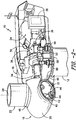
- the hub crane assembly 52 includes an adjustable articulating arm 54, a first hoist 64, a support component 65, and an optional anchoring point 66.
- the articulating arm 54 is mounted on the hub 20 of the wind turbine 10 via a hinge point 57.
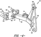
- the articulating arm 54 may include a first arm portion 55 and a second arm portion 56. More specifically, as shown, the first and second arm portions 55, 56 may be secured together at a fixed attachment location 61. For example, as shown in FIG.
- the fixed attachment location 61 may include the second arm portion 56 of the articulating arm 54 being secured within a slot 67 defined in the first arm portion 55.
- an end of the second arm portion 56 may fit within the slot 67 of the first arm portion 55 and secured therein, e.g. via mechanical fasteners, adhesives, welding, or similar.
- the first and second arm portions 55, 56 may be secured together without the use of the slot 67.
- the articulating arm 54 may also include a handle 73 (e.g. mounted to the second arm portion 56) such that an operator can easily lift and move the articulating arm 54.
- the articulating arm 54 may be mounted on the hub 20 of the wind turbine 10 at a first height H 1 , whereas the first hoist 64 is mounted at a second height H 2 of the wind turbine 10. Further, as shown in the illustrated embodiment, the second height H 2 is greater than the first height H 1 .
- the articulating arm 54 may be mountable to a front location of the hub 20, whereas the first hoist 64 may be mountable to a top location of at least one of the hub 20 or the nacelle 16 of the wind turbine 10. As such, the articulating arm 54 may be easily mounted to the front location from within the hub 20 such that an operator is not required to leave the hub 20.
- the adjustable articulating arm 54 may be mounted to the hub 20 via a mounting plate 60. More specifically, as shown, the second arm portion 56 of the articulating arm 54 may be mounted to the hub 20 via the mounting plate 60 at the hinge point 57.
- the mounting plate 60 may include a plurality of bolt holes and corresponding bolts 62 that can be secured via a plurality of nuts (not shown) from inside the hub 20.
- the mounting plate 60 may include the hinge point 57.
- the second arm portion 56 of the articulating arm 54 may be secured to the mounting plate 60 at the hinge point 57 via a pin 69.
- the support component 65 is secured to the first hoist 64 and a first attachment point 58 of the articulating arm 54. More specifically, as shown, the support component 65 may include a strap, a sling, or similar.
- the anchoring point 66 is configured to secure the first hoist 64 to the hub 20 of the wind turbine 10. More particularly, in certain embodiments, the anchoring point 66 may include a swivel bolt or any other suitable fastener so as to further secure the first hoist 64 to the hub 20.
- the hub crane assembly 52 may also include a second hoist 68 secured to the articulating arm 54 at an opposing, second attachment point 59 of the first arm portion 55.
- the second hoist 68 is configured to lift or lower a load 70 from a support surface (e.g. support surface 14) to the hub 20.
- the first and second hoists 55, 56 described herein may include any suitable hoist apparatus now known or later developed that is capable of hoisting (i.e. lifting or lowering) a load.
- the present disclosure is not limited to any particular hoist configuration.
- the first and second hoists 55, 56 may be controller manually, e.g. via an operator, or automatically, e.g. via a controller.
- the first hoist 64 is configured to rotate the articulating arm 54 about the hinge point 57 via the support component 65 such that, as the articulating arm 54 rotates, a clearance distance (e.g. as illustrated by distances 72 and 74) between the wind turbine 10 and the articulating arm 54 (and also the load 70) changes.
- a clearance distance e.g. as illustrated by distances 72 and 74
- FIG. 12 a flow diagram of one embodiment of a method 100 for lifting or lowering a wind turbine component between a support surface (e.g. support surface 14) and a hub 20 of a wind turbine 10 using the hub crane assembly 52 of the present disclosure is illustrated.
- the method 100 includes securing the adjustable articulating arm 54 at the first height H 1 on the hub 20 of the wind turbine 10. More specifically, as shown in FIGS. 5 and 6 , the articulating arm 54 may be installed in a first position closest to the hub 20. This position allows an operator to easily install the mounting plate 60 as described above and secure the articulating arm 54 thereto without having to leave the inside of the hub 20.
- the method 100 includes securing a first hoist 64 at a second height H 2 of the wind turbine 10, wherein the second height H 2 is greater than the first height H 1 .
- the first hoist 64 can also be installed from inside the hub 20 to a location atop the hub 20.
- the method 100 includes connecting a support component 65 to the first hoist 64 and a first attachment point 58 of the articulating arm 54.
- the support component 65 may be routed from the first hoist 64 mounted atop the hub 20 to the articulating arm 54 and secured to the first attachment point 58.
- the method 100 includes securing a second hoist 68 to a second attachment point 59 of the articulating arm 54.
- an operator may also secure the second hoist 68 to the second attachment point 59 from inside of the hub 20.
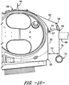
- the method 100 includes securing a load 70 to the second hoist 65 via at least one support line 76 ( FIGS 10 and 11 ).
- the method 100 includes lifting or lowering, via coordinated hoist operation of the first and second hoists 64, 68, the articulating arm 54 and the load 70. Accordingly, as the load 70 is lifted or lowered via the second hoist 68, the first hoist 64 rotates the articulating arm 54 about the hinge point 57 such that the clearance distance 72, 74 between the load 70 and the wind turbine 10 (e.g. the tower 12) changes.
- the second hoist 68 is suspended outside of the hub 20 and the articulating arm 54 extends outward from the hub 20 at its maximum length. (See e.g., FIGS. 8-10 ; distance 72).
- the clearance distance 72 is maximized via the adjustable articulating arm 54 so as to prevent collisions between the load 70 and the tower 12 of the wind turbine 10.
- the articulating arm 54 continues to rotate upwards towards the first hoist 54 until the load 70 has reached an opening 30 of the hub 20. At this time, an operator can easily retrieve the load 70 from the support line 76 and bring the load within the hub 20.
- the load 70 described herein may include any suitable wind turbine components, such as, for example, the pitch drive mechanism 32 and/or any other components.
- Reference Character Component 10 Wind Turbine 12 Tower 14 Support Surface 16 Nacelle 18 Rotor 20 Hub 22 Rotor Blades 24 Generator 26 Controller 28 Pitch Axis 30 Opening 32 Pitch Drive Mechanism 34 Rotor Shaft 36 Generator Shaft 38 Gearbox 40 Pitch Drive Motor 42 Pitch Drive Gearbox 44 Pitch Drive Pinion 46 Pitch Bearing 48 Bedplate Support Frame 50 Torque Supports 52 Hub Crane Assembly 54 Articulating Arm 55 First Arm Portion 56 Second Arm Portion 57 Hinge Point 58 First Attachment Point 59 Second Attachment Point 60 Mounting Plate 61 Fixed Attachment Location 62 Bolts 63 Bolt Holes 64 First Hoist 65 Support Component 66 Anchoring Point 67 Slot 69 Pin 68 Second Hoist 69 Pin 70 Load 73 Handle 72 First Distance 74 Second Distance 76 Support Line 100 Method 102 Method Step 104 Method Step 106 Method Step 108 Method Step 110 Method Step 112 Method Step
Landscapes
- Engineering & Computer Science (AREA)
- Mechanical Engineering (AREA)
- Life Sciences & Earth Sciences (AREA)
- Sustainable Development (AREA)
- Sustainable Energy (AREA)
- Chemical & Material Sciences (AREA)
- Combustion & Propulsion (AREA)
- General Engineering & Computer Science (AREA)
- Wind Motors (AREA)
- Civil Engineering (AREA)
- Structural Engineering (AREA)
Claims (15)
- Ensemble grue (52) pour moyeu d'une éolienne (10), comprenant :un bras articulé réglable (54), montable à une première hauteur sur le moyeu de l'éolienne (10) en un point d'articulation (57) ;un premier palan (64) montable à une seconde hauteur de l'éolienne (10), la seconde hauteur étant supérieure à la première hauteur ; etun élément de soutien (65), fixé au premier palan (64) et en un premier point de fixation du bras articulé (54),dans lequel le premier palan (64) est conçu pour faire tourner le bras d'articulation (54) autour du point d'articulation (57) par le biais du élément de soutien (65) de sorte que, lorsque le bras d'articulation (54) tourne, la distance de dégagement varie entre l'éolienne (10) et le bras articulé (54).
- Ensemble grue (52) pour moyeu selon la revendication 1, comprenant en outre un second palan (68) fixé au bras d'articulation (54) en un second point de fixation opposé (59), le second palan (68) étant conçu pour lever ou pour abaisser une charge (70) d'une surface de soutien (14) au moyeu (20).
- Ensemble grue (52) pour moyeu selon la revendication 1 ou 2, dans lequel le bras d'articulation (54) comprend une première partie de bras (55) et une seconde partie de bras (56), les première et seconde parties de bras (55, 56) étant fixées ensemble à un emplacement fixe de fixation (61).
- Ensemble grue (52) pour moyeu selon la revendication 3, dans lequel la seconde partie de bras (56) du bras articulé (54) de l'emplacement fixe de fixation (61) est fixée dans une fente (67) définie dans la première partie de bras (55).
- Ensemble grue (52) pour moyeu selon la revendication 3, dans lequel la seconde partie de bras (56) du bras articulé (54) est montée sur le moyeu (20) par le biais d'une plaque de montage (60) au niveau du point d'articulation (57).
- Ensemble grue (52) pour moyeu selon l'une quelconque des revendications précédentes, comprenant en outre un point d'ancrage (66) conçu pour fixer le premier palan (64) à le moyeu (20) de l'éolienne (10).
- Ensemble grue (52) pour moyeu selon la revendication 6, dans lequel le point d'ancrage (66) comprend un boulon pivotant.
- Ensemble grue (52) pour moyeu selon l'une quelconque des revendications précédentes, dans lequel le bras d'articulation (54) est montable sur un emplacement avant du moyeu (20).
- Ensemble grue (52) pour moyeu selon l'une quelconque des revendications précédentes, dans lequel le premier palan (64) peut être monté à un emplacement supérieur du moyeu (20) et/ou d'une nacelle (16) de l'éolienne (10).
- Ensemble grue (52) pour moyeu selon l'une quelconque des revendications précédentes, dans lequel l'élément de soutien (65) comprend une sangle et/ou une élingue.
- Procédé (100) d'élévation ou d'abaissement d'un élément d'éolienne (10) entre une surface de soutien (14) et un moyeu (20) d'une éolienne (10), utilisant un ensemble grue pour moyeu selon l'une quelconque des revendications 1 à 10, le procédé (100) comprenant :la fixation d'un bras articulé réglable (54) à une première hauteur sur le moyeu (20) de l'éolienne (10) ;la fixation d'un premier palan (64) à une seconde hauteur de l'éolienne (10), la seconde hauteur étant supérieure à la première hauteur ;la liaison d'un élément de soutien (65) au premier palan (64) et à un premier point de fixation (58) du bras articulé (54) ;la fixation d'un second palan (68) à un second point de fixation (59) du bras articulé (54) ;la fixation d'une charge (70) au second palan (68) par le biais d'au moins une sangle ; etle levage ou l'abaissement, par le biais d'une opération de levage coordonnée des premier et second palans (68), du bras articulé (54) et de la charge (70),et lorsque la charge (70) est soulevée ou abaissée par le second palan (68), le premier palan (64) fait tourner le bras articulé (54) autour d'un point d'articulation (57) de sorte qu'une distance de dégagement varie entre la charge (70) et l'éolienne (10).
- Procédé (100) selon la revendication 11, comprenant en outre la fixation du bras articulé réglable (54) à la première hauteur sur le moyeu par le biais d'une plaque de montage (60) à partir de l'intérieur du moyeu (20).
- Éolienne (10), comprenant :une tour (12) montée sur une surface de soutien (14) ;une nacelle (16) montée au sommet de la tour (12) ;un rotor (18) monté sur la nacelle (16), le rotor (18) comprenant un moyeu (20) sur lequel sont montées une ou plusieurs pales de rotor (22) ; etun ensemble grue pour moyeu (52) selon la revendication 1.
- Éolienne (10) selon la revendication 13, comprenant en outre un second palan (68) fixé au bras articulé (54) en un second point de fixation opposé (59), le second palan (68) étant conçu pour lever ou pour abaisser une charge (70) d'une surface de soutien (14) au moyeu (20).
- Éolienne (10) selon la revendication 13 ou 14, dans laquelle le bras articulé (54) comprend une première partie de bras (55) et une seconde partie de bras (56), les première et seconde parties de bras (55, 56) étant fixées ensemble en un emplacement fixe de fixation (61), la seconde partie de bras (56) du bras articulé (54) étant montée sur le moyeu par le biais d'une plaque de montage (60) au niveau du point d'articulation (57).
Priority Applications (4)
| Application Number | Priority Date | Filing Date | Title |
|---|---|---|---|
| ES17382156T ES2876008T3 (es) | 2017-03-29 | 2017-03-29 | Conjunto de grúa de buje para una turbina eólica |
| DK17382156.2T DK3382200T3 (da) | 2017-03-29 | 2017-03-29 | Navkrananordning til en vindmølle |
| EP17382156.2A EP3382200B1 (fr) | 2017-03-29 | 2017-03-29 | Ensemble grue à plate-forme pour une éolienne |
| US15/967,782 US10801473B2 (en) | 2017-03-29 | 2018-05-01 | Hub crane assembly for a wind turbine |
Applications Claiming Priority (1)
| Application Number | Priority Date | Filing Date | Title |
|---|---|---|---|
| EP17382156.2A EP3382200B1 (fr) | 2017-03-29 | 2017-03-29 | Ensemble grue à plate-forme pour une éolienne |
Publications (2)
| Publication Number | Publication Date |
|---|---|
| EP3382200A1 EP3382200A1 (fr) | 2018-10-03 |
| EP3382200B1 true EP3382200B1 (fr) | 2020-12-30 |
Family
ID=58501419
Family Applications (1)
| Application Number | Title | Priority Date | Filing Date |
|---|---|---|---|
| EP17382156.2A Active EP3382200B1 (fr) | 2017-03-29 | 2017-03-29 | Ensemble grue à plate-forme pour une éolienne |
Country Status (4)
| Country | Link |
|---|---|
| US (1) | US10801473B2 (fr) |
| EP (1) | EP3382200B1 (fr) |
| DK (1) | DK3382200T3 (fr) |
| ES (1) | ES2876008T3 (fr) |
Families Citing this family (3)
| Publication number | Priority date | Publication date | Assignee | Title |
|---|---|---|---|---|
| CN109139394B (zh) * | 2018-10-31 | 2021-02-26 | 北京金风科创风电设备有限公司 | 风力发电机组的轮毂、叶轮以及变桨控制部件的安装方法 |
| EP4048887A1 (fr) * | 2019-10-22 | 2022-08-31 | LiftWerx Holdings Inc. | Système de levage pour une pale de rotor d'une éolienne |
| US11946454B2 (en) * | 2021-11-24 | 2024-04-02 | Ge Infrastructure Technology Llc | Mounting tool for fastener assembly and disassembly within wind turbine hubs |
Family Cites Families (46)
| Publication number | Priority date | Publication date | Assignee | Title |
|---|---|---|---|---|
| AT401674B (de) | 1994-09-26 | 1996-11-25 | Hehenberger Gerald Dipl Ing | Windkraftanlage |
| DE10224439C5 (de) | 2002-06-01 | 2009-12-31 | Aloys Wobben | Verfahren zur Montage/Demontage von Komponenten einer Windenergieanlage |
| DE10303555B4 (de) | 2003-01-29 | 2007-01-25 | Aloys Wobben | Verfahren zur kranlosen Montage eines Rotorblattes einer Windenergieanlage |
| DE102004056340B4 (de) | 2004-11-22 | 2010-11-18 | Repower Systems Ag | Vorrichtung und Verfahren zur Montage und/oder Demontage eines Bauteils einer Windkraftanlage |
| WO2008069818A1 (fr) | 2006-12-08 | 2008-06-12 | General Electric Company | Grue à plate-forme mobile pour pièces d'éolienne |
| ES2322000B1 (es) | 2006-12-14 | 2010-03-11 | GAMESA INNOVATION & TECHNOLOGY, S.L. | Un metodo para montar el rotor de un aerogenerador. |
| CN101631954B (zh) | 2007-01-24 | 2012-10-03 | 维斯塔斯风力系统有限公司 | 将风轮机部件如风轮机轮毂从运输位置移动到在机舱、主轴或轮毂之中或之上的装配位置的方法,处理装置,风轮机轮毂及其使用 |
| CN201343379Y (zh) | 2008-02-04 | 2009-11-11 | 大连华锐股份有限公司 | 用于大型风电设备维修的起重机 |
| US8104631B2 (en) * | 2008-07-24 | 2012-01-31 | General Electric Company | Portable crane system for wind turbine components |
| US20100139062A1 (en) | 2009-02-25 | 2010-06-10 | General Electric Company | Lowering and raising a single wind turbine rotor blade from six-o'clock position |
| DK2226502T3 (da) | 2009-03-03 | 2013-03-25 | Siemens Ag | Fremgangsmåde og indretning til installering af en vindmølle |
| US20100254813A1 (en) | 2009-04-02 | 2010-10-07 | Frontier Pro Services | Winch servicing of wind turbines |
| KR101054919B1 (ko) | 2009-04-03 | 2011-08-05 | 주식회사 디엠에스 | 풍력 발전기 |
| US8118552B2 (en) | 2009-10-06 | 2012-02-21 | General Electric Company | Apparatus and method for manipulating a component of a wind turbine |
| CN101929443A (zh) | 2009-10-26 | 2010-12-29 | 华锐风电科技(集团)股份有限公司 | 风电机组叶片自更换装置及其工作方法 |
| CA2784625A1 (fr) | 2009-11-30 | 2011-06-03 | Clipper Windpower, Inc. | Appareil d'abaissement d'une pale d'eolienne |
| WO2011082710A1 (fr) | 2010-01-07 | 2011-07-14 | Vestas Wind Systems A/S | Procédé pour soulever un composant d'éolienne vers une partie supérieure d'une tour d'éolienne |
| DK2369174T3 (da) | 2010-03-09 | 2013-03-11 | Lm Glasfiber As | En fremgangsmåde til kranfri montering eller afmontering af en vindmøllevinge på et vindenergianlæg |
| GB2483677B (en) | 2010-09-15 | 2014-04-16 | Vestas Wind Sys As | An apparatus for and method of mounting wind turbine blades on a wind turbine tower |
| US8789274B2 (en) | 2010-09-23 | 2014-07-29 | Northern Power Systems, Inc. | Method and system for servicing a horizontal-axis wind power unit |
| ES2564260T3 (es) | 2010-11-18 | 2016-03-21 | Vestas Wind Systems A/S | Método para manipular sin grúa una pala de turbina eólica por medio de un buje de turbina |
| US20110206510A1 (en) | 2010-12-20 | 2011-08-25 | Reinhard Langen | Modular rotor blade and method for mounting a wind turbine |
| US8807923B2 (en) | 2011-02-07 | 2014-08-19 | Vestas Wind Systems A/S | Access apparatus for a wind turbine and method of using same |
| KR101235358B1 (ko) | 2011-02-22 | 2013-02-20 | 주식회사 디엠에스 | 풍력 발전기 |
| DK2686550T3 (en) | 2011-03-17 | 2016-10-24 | Vestas Wind Sys As | An apparatus for gaining access to the nacelle of a wind turbine and associated methods |
| KR101362936B1 (ko) | 2012-01-17 | 2014-02-14 | 삼성중공업 주식회사 | 풍력발전기의 블레이드 이동 장치, 이를 이용한 피치 베어링 수리 방법 및 이를 구비한 풍력 발전기 |
| US9446446B2 (en) | 2012-06-04 | 2016-09-20 | Acciona Windpower, S.A. | System and method for assembling and disassembling components from a wind power turbine |
| EP2724020B1 (fr) | 2012-07-31 | 2015-04-08 | Mitsubishi Heavy Industries, Ltd. | Système de rail pour une éolienne |
| JP5714178B2 (ja) | 2012-07-31 | 2015-05-07 | 三菱重工業株式会社 | クレーン装置 |
| CN104781181B (zh) | 2012-08-30 | 2019-03-19 | 疾风有限公司 | 用于组装结构的装置和方法 |
| US9745953B2 (en) | 2012-10-23 | 2017-08-29 | General Electric Company | Method and system for replacing a single wind turbine blade |
| CN202880704U (zh) | 2012-11-14 | 2013-04-17 | 神华集团有限责任公司 | 用于风电机的轮毂的起吊工具 |
| SG11201504911YA (en) | 2012-12-20 | 2015-07-30 | High Wind N V | Device and method for placing components of a structure |
| CN203079518U (zh) | 2013-01-16 | 2013-07-24 | 江苏新誉重工科技有限公司 | 风力发电机组风轮内部大部件起吊装置 |
| US9651020B2 (en) * | 2013-09-24 | 2017-05-16 | General Electric Company | Portable crane for use in wind turbines |
| JP2015075037A (ja) | 2013-10-09 | 2015-04-20 | 三菱重工業株式会社 | 風車用のブレード着脱方法及びブレード着脱装置 |
| US10260483B2 (en) | 2013-12-10 | 2019-04-16 | Pp Energy Aps | Fixation device for servicing wind turbine components |
| JP6290647B2 (ja) * | 2014-02-19 | 2018-03-07 | 三菱重工業株式会社 | 風力発電機用のメンテナンス装置及びメンテナンス方法 |
| US9638163B2 (en) | 2014-02-20 | 2017-05-02 | General Electric Company | Methods and systems for removing and/or installing wind turbine rotor blades |
| US9964095B2 (en) | 2014-04-21 | 2018-05-08 | General Electric Company | Method and system for servicing wind turbine rotor |
| JP2017515048A (ja) | 2014-04-30 | 2017-06-08 | ウィンドケア インディア プライベート リミテッドWindcare India Pvt Ltd | 風力タービンブレードの解体および再取り付け方法およびシステム |
| DK178406B1 (en) | 2014-06-12 | 2016-02-08 | Envision Energy Denmark Aps | Lifting device for rotor assembly and method thereof |
| ES2556997B1 (es) | 2014-07-07 | 2016-12-12 | Gamesa Innovation & Technology, S.L. | Método y dispositivo de sustitución de pala en aerogeneradores |
| US9850880B2 (en) | 2014-11-20 | 2017-12-26 | General Electric Company | System for servicing wind turbine rotor |
| CN105984818A (zh) | 2015-03-02 | 2016-10-05 | 上海电气风电设备有限公司 | 一种新型的风电机组轮毂内起吊装置 |
| CN204675721U (zh) | 2015-03-02 | 2015-09-30 | 上海电气风电设备有限公司 | 一种新型的风电机组轮毂内起吊装置 |
-
2017
- 2017-03-29 ES ES17382156T patent/ES2876008T3/es active Active
- 2017-03-29 EP EP17382156.2A patent/EP3382200B1/fr active Active
- 2017-03-29 DK DK17382156.2T patent/DK3382200T3/da active
-
2018
- 2018-05-01 US US15/967,782 patent/US10801473B2/en active Active
Non-Patent Citations (1)
| Title |
|---|
| None * |
Also Published As
| Publication number | Publication date |
|---|---|
| EP3382200A1 (fr) | 2018-10-03 |
| US20180297822A1 (en) | 2018-10-18 |
| US10801473B2 (en) | 2020-10-13 |
| DK3382200T3 (da) | 2021-03-29 |
| ES2876008T3 (es) | 2021-11-11 |
Similar Documents
| Publication | Publication Date | Title |
|---|---|---|
| EP3001029B1 (fr) | Systèmes de contrepoids pour une éolienne et procédés | |
| US9651020B2 (en) | Portable crane for use in wind turbines | |
| EP3431751B1 (fr) | Système et procédé pour suspendre une pale de rotor d'une tour supérieure d'éolienne | |
| US10443572B2 (en) | System and method for removing or installing a main shaft of a wind turbine | |
| EP3502465B1 (fr) | Accessoires de levage pour éoliennes, kits et procédés | |
| US10801473B2 (en) | Hub crane assembly for a wind turbine | |
| US12078147B2 (en) | Blade lifting assembly for mounting a blade to or unmounting a blade from a rotor hub of a wind turbine | |
| US11965479B2 (en) | System and method for repairing a gearbox of a wind turbine uptower | |
| US10641042B2 (en) | External ladder assembly for wind turbine nacelle | |
| US9803739B2 (en) | Gearbox adjustment system | |
| US11353007B2 (en) | Method of mounting a nacelle of a wind turbine and assembling set of parts of a wind turbine | |
| US10570888B2 (en) | Working platform within a nacelle of a wind turbine | |
| US12281636B2 (en) | Method of servicing or installing a component of a wind turbine using a crane | |
| CN211971517U (zh) | 一种能调整风电叶片空中姿态的吊具 | |
| US11686291B2 (en) | Method of mounting blades to a rotor hub of a wind turbine | |
| EP3364023B1 (fr) | Système et procédé pour retirer ou installer un arbre principal d'une éolienne | |
| EP3615794B1 (fr) | Appareil et procédé pour retirer ou installer une unité de palier dans un châssis de nacelle d'éolienne avec un support de palier réglable |
Legal Events
| Date | Code | Title | Description |
|---|---|---|---|
| PUAI | Public reference made under article 153(3) epc to a published international application that has entered the european phase |
Free format text: ORIGINAL CODE: 0009012 |
|
| STAA | Information on the status of an ep patent application or granted ep patent |
Free format text: STATUS: REQUEST FOR EXAMINATION WAS MADE |
|
| 17P | Request for examination filed |
Effective date: 20170329 |
|
| AK | Designated contracting states |
Kind code of ref document: A1 Designated state(s): AL AT BE BG CH CY CZ DE DK EE ES FI FR GB GR HR HU IE IS IT LI LT LU LV MC MK MT NL NO PL PT RO RS SE SI SK SM TR |
|
| AX | Request for extension of the european patent |
Extension state: BA ME |
|
| RBV | Designated contracting states (corrected) |
Designated state(s): AL AT BE BG CH CY CZ DE DK EE ES FI FR GB GR HR HU IE IS IT LI LT LU LV MC MK MT NL NO PL PT RO RS SE SI SK SM TR |
|
| GRAP | Despatch of communication of intention to grant a patent |
Free format text: ORIGINAL CODE: EPIDOSNIGR1 |
|
| STAA | Information on the status of an ep patent application or granted ep patent |
Free format text: STATUS: GRANT OF PATENT IS INTENDED |
|
| INTG | Intention to grant announced |
Effective date: 20200603 |
|
| GRAS | Grant fee paid |
Free format text: ORIGINAL CODE: EPIDOSNIGR3 |
|
| GRAJ | Information related to disapproval of communication of intention to grant by the applicant or resumption of examination proceedings by the epo deleted |
Free format text: ORIGINAL CODE: EPIDOSDIGR1 |
|
| GRAL | Information related to payment of fee for publishing/printing deleted |
Free format text: ORIGINAL CODE: EPIDOSDIGR3 |
|
| STAA | Information on the status of an ep patent application or granted ep patent |
Free format text: STATUS: REQUEST FOR EXAMINATION WAS MADE |
|
| INTC | Intention to grant announced (deleted) | ||
| GRAJ | Information related to disapproval of communication of intention to grant by the applicant or resumption of examination proceedings by the epo deleted |
Free format text: ORIGINAL CODE: EPIDOSDIGR1 |
|
| GRAL | Information related to payment of fee for publishing/printing deleted |
Free format text: ORIGINAL CODE: EPIDOSDIGR3 |
|
| GRAP | Despatch of communication of intention to grant a patent |
Free format text: ORIGINAL CODE: EPIDOSNIGR1 |
|
| STAA | Information on the status of an ep patent application or granted ep patent |
Free format text: STATUS: GRANT OF PATENT IS INTENDED |
|
| GRAA | (expected) grant |
Free format text: ORIGINAL CODE: 0009210 |
|
| STAA | Information on the status of an ep patent application or granted ep patent |
Free format text: STATUS: THE PATENT HAS BEEN GRANTED |
|
| INTG | Intention to grant announced |
Effective date: 20201113 |
|
| AK | Designated contracting states |
Kind code of ref document: B1 Designated state(s): AL AT BE BG CH CY CZ DE DK EE ES FI FR GB GR HR HU IE IS IT LI LT LU LV MC MK MT NL NO PL PT RO RS SE SI SK SM TR |
|
| REG | Reference to a national code |
Ref country code: GB Ref legal event code: FG4D |
|
| REG | Reference to a national code |
Ref country code: AT Ref legal event code: REF Ref document number: 1350176 Country of ref document: AT Kind code of ref document: T Effective date: 20210115 |
|
| REG | Reference to a national code |
Ref country code: DE Ref legal event code: R096 Ref document number: 602017030394 Country of ref document: DE |
|
| REG | Reference to a national code |
Ref country code: IE Ref legal event code: FG4D |
|
| REG | Reference to a national code |
Ref country code: DK Ref legal event code: T3 Effective date: 20210325 |
|
| PG25 | Lapsed in a contracting state [announced via postgrant information from national office to epo] |
Ref country code: RS Free format text: LAPSE BECAUSE OF FAILURE TO SUBMIT A TRANSLATION OF THE DESCRIPTION OR TO PAY THE FEE WITHIN THE PRESCRIBED TIME-LIMIT Effective date: 20201230 Ref country code: NO Free format text: LAPSE BECAUSE OF FAILURE TO SUBMIT A TRANSLATION OF THE DESCRIPTION OR TO PAY THE FEE WITHIN THE PRESCRIBED TIME-LIMIT Effective date: 20210330 Ref country code: GR Free format text: LAPSE BECAUSE OF FAILURE TO SUBMIT A TRANSLATION OF THE DESCRIPTION OR TO PAY THE FEE WITHIN THE PRESCRIBED TIME-LIMIT Effective date: 20210331 Ref country code: FI Free format text: LAPSE BECAUSE OF FAILURE TO SUBMIT A TRANSLATION OF THE DESCRIPTION OR TO PAY THE FEE WITHIN THE PRESCRIBED TIME-LIMIT Effective date: 20201230 |
|
| REG | Reference to a national code |
Ref country code: AT Ref legal event code: MK05 Ref document number: 1350176 Country of ref document: AT Kind code of ref document: T Effective date: 20201230 |
|
| PG25 | Lapsed in a contracting state [announced via postgrant information from national office to epo] |
Ref country code: SE Free format text: LAPSE BECAUSE OF FAILURE TO SUBMIT A TRANSLATION OF THE DESCRIPTION OR TO PAY THE FEE WITHIN THE PRESCRIBED TIME-LIMIT Effective date: 20201230 Ref country code: BG Free format text: LAPSE BECAUSE OF FAILURE TO SUBMIT A TRANSLATION OF THE DESCRIPTION OR TO PAY THE FEE WITHIN THE PRESCRIBED TIME-LIMIT Effective date: 20210330 Ref country code: LV Free format text: LAPSE BECAUSE OF FAILURE TO SUBMIT A TRANSLATION OF THE DESCRIPTION OR TO PAY THE FEE WITHIN THE PRESCRIBED TIME-LIMIT Effective date: 20201230 |
|
| REG | Reference to a national code |
Ref country code: NL Ref legal event code: MP Effective date: 20201230 |
|
| PG25 | Lapsed in a contracting state [announced via postgrant information from national office to epo] |
Ref country code: HR Free format text: LAPSE BECAUSE OF FAILURE TO SUBMIT A TRANSLATION OF THE DESCRIPTION OR TO PAY THE FEE WITHIN THE PRESCRIBED TIME-LIMIT Effective date: 20201230 |
|
| REG | Reference to a national code |
Ref country code: LT Ref legal event code: MG9D |
|
| PG25 | Lapsed in a contracting state [announced via postgrant information from national office to epo] |
Ref country code: SK Free format text: LAPSE BECAUSE OF FAILURE TO SUBMIT A TRANSLATION OF THE DESCRIPTION OR TO PAY THE FEE WITHIN THE PRESCRIBED TIME-LIMIT Effective date: 20201230 Ref country code: PT Free format text: LAPSE BECAUSE OF FAILURE TO SUBMIT A TRANSLATION OF THE DESCRIPTION OR TO PAY THE FEE WITHIN THE PRESCRIBED TIME-LIMIT Effective date: 20210430 Ref country code: RO Free format text: LAPSE BECAUSE OF FAILURE TO SUBMIT A TRANSLATION OF THE DESCRIPTION OR TO PAY THE FEE WITHIN THE PRESCRIBED TIME-LIMIT Effective date: 20201230 Ref country code: CZ Free format text: LAPSE BECAUSE OF FAILURE TO SUBMIT A TRANSLATION OF THE DESCRIPTION OR TO PAY THE FEE WITHIN THE PRESCRIBED TIME-LIMIT Effective date: 20201230 Ref country code: EE Free format text: LAPSE BECAUSE OF FAILURE TO SUBMIT A TRANSLATION OF THE DESCRIPTION OR TO PAY THE FEE WITHIN THE PRESCRIBED TIME-LIMIT Effective date: 20201230 Ref country code: LT Free format text: LAPSE BECAUSE OF FAILURE TO SUBMIT A TRANSLATION OF THE DESCRIPTION OR TO PAY THE FEE WITHIN THE PRESCRIBED TIME-LIMIT Effective date: 20201230 |
|
| PG25 | Lapsed in a contracting state [announced via postgrant information from national office to epo] |
Ref country code: PL Free format text: LAPSE BECAUSE OF FAILURE TO SUBMIT A TRANSLATION OF THE DESCRIPTION OR TO PAY THE FEE WITHIN THE PRESCRIBED TIME-LIMIT Effective date: 20201230 Ref country code: AT Free format text: LAPSE BECAUSE OF FAILURE TO SUBMIT A TRANSLATION OF THE DESCRIPTION OR TO PAY THE FEE WITHIN THE PRESCRIBED TIME-LIMIT Effective date: 20201230 |
|
| PG25 | Lapsed in a contracting state [announced via postgrant information from national office to epo] |
Ref country code: IS Free format text: LAPSE BECAUSE OF FAILURE TO SUBMIT A TRANSLATION OF THE DESCRIPTION OR TO PAY THE FEE WITHIN THE PRESCRIBED TIME-LIMIT Effective date: 20210430 |
|
| REG | Reference to a national code |
Ref country code: DE Ref legal event code: R097 Ref document number: 602017030394 Country of ref document: DE |
|
| PG25 | Lapsed in a contracting state [announced via postgrant information from national office to epo] |
Ref country code: MC Free format text: LAPSE BECAUSE OF FAILURE TO SUBMIT A TRANSLATION OF THE DESCRIPTION OR TO PAY THE FEE WITHIN THE PRESCRIBED TIME-LIMIT Effective date: 20201230 Ref country code: IT Free format text: LAPSE BECAUSE OF FAILURE TO SUBMIT A TRANSLATION OF THE DESCRIPTION OR TO PAY THE FEE WITHIN THE PRESCRIBED TIME-LIMIT Effective date: 20201230 Ref country code: AL Free format text: LAPSE BECAUSE OF FAILURE TO SUBMIT A TRANSLATION OF THE DESCRIPTION OR TO PAY THE FEE WITHIN THE PRESCRIBED TIME-LIMIT Effective date: 20201230 |
|
| REG | Reference to a national code |
Ref country code: CH Ref legal event code: PL |
|
| PLBE | No opposition filed within time limit |
Free format text: ORIGINAL CODE: 0009261 |
|
| STAA | Information on the status of an ep patent application or granted ep patent |
Free format text: STATUS: NO OPPOSITION FILED WITHIN TIME LIMIT |
|
| REG | Reference to a national code |
Ref country code: ES Ref legal event code: FG2A Ref document number: 2876008 Country of ref document: ES Kind code of ref document: T3 Effective date: 20211111 |
|
| GBPC | Gb: european patent ceased through non-payment of renewal fee |
Effective date: 20210330 |
|
| 26N | No opposition filed |
Effective date: 20211001 |
|
| REG | Reference to a national code |
Ref country code: BE Ref legal event code: MM Effective date: 20210331 |
|
| PG25 | Lapsed in a contracting state [announced via postgrant information from national office to epo] |
Ref country code: FR Free format text: LAPSE BECAUSE OF NON-PAYMENT OF DUE FEES Effective date: 20210331 Ref country code: GB Free format text: LAPSE BECAUSE OF NON-PAYMENT OF DUE FEES Effective date: 20210330 Ref country code: IE Free format text: LAPSE BECAUSE OF NON-PAYMENT OF DUE FEES Effective date: 20210329 Ref country code: LU Free format text: LAPSE BECAUSE OF NON-PAYMENT OF DUE FEES Effective date: 20210329 Ref country code: LI Free format text: LAPSE BECAUSE OF NON-PAYMENT OF DUE FEES Effective date: 20210331 Ref country code: CH Free format text: LAPSE BECAUSE OF NON-PAYMENT OF DUE FEES Effective date: 20210331 |
|
| PG25 | Lapsed in a contracting state [announced via postgrant information from national office to epo] |
Ref country code: SI Free format text: LAPSE BECAUSE OF FAILURE TO SUBMIT A TRANSLATION OF THE DESCRIPTION OR TO PAY THE FEE WITHIN THE PRESCRIBED TIME-LIMIT Effective date: 20201230 |
|
| PG25 | Lapsed in a contracting state [announced via postgrant information from national office to epo] |
Ref country code: IS Free format text: LAPSE BECAUSE OF FAILURE TO SUBMIT A TRANSLATION OF THE DESCRIPTION OR TO PAY THE FEE WITHIN THE PRESCRIBED TIME-LIMIT Effective date: 20210430 |
|
| PG25 | Lapsed in a contracting state [announced via postgrant information from national office to epo] |
Ref country code: BE Free format text: LAPSE BECAUSE OF NON-PAYMENT OF DUE FEES Effective date: 20210331 |
|
| PG25 | Lapsed in a contracting state [announced via postgrant information from national office to epo] |
Ref country code: NL Free format text: LAPSE BECAUSE OF NON-PAYMENT OF DUE FEES Effective date: 20201230 Ref country code: CY Free format text: LAPSE BECAUSE OF FAILURE TO SUBMIT A TRANSLATION OF THE DESCRIPTION OR TO PAY THE FEE WITHIN THE PRESCRIBED TIME-LIMIT Effective date: 20201230 |
|
| P01 | Opt-out of the competence of the unified patent court (upc) registered |
Effective date: 20230530 |
|
| PG25 | Lapsed in a contracting state [announced via postgrant information from national office to epo] |
Ref country code: SM Free format text: LAPSE BECAUSE OF FAILURE TO SUBMIT A TRANSLATION OF THE DESCRIPTION OR TO PAY THE FEE WITHIN THE PRESCRIBED TIME-LIMIT Effective date: 20201230 Ref country code: HU Free format text: LAPSE BECAUSE OF FAILURE TO SUBMIT A TRANSLATION OF THE DESCRIPTION OR TO PAY THE FEE WITHIN THE PRESCRIBED TIME-LIMIT; INVALID AB INITIO Effective date: 20170329 |
|
| REG | Reference to a national code |
Ref country code: DE Ref legal event code: R081 Ref document number: 602017030394 Country of ref document: DE Owner name: GENERAL ELECTRIC RENOVABLES ESPANA, S.L., ES Free format text: FORMER OWNER: GENERAL ELECTRIC CO., SCHENECTADY, N.Y., US Ref country code: DE Ref legal event code: R082 Ref document number: 602017030394 Country of ref document: DE Representative=s name: ZIMMERMANN & PARTNER PATENTANWAELTE MBB, DE |
|
| REG | Reference to a national code |
Ref country code: DE Ref legal event code: R082 Ref document number: 602017030394 Country of ref document: DE Representative=s name: ZIMMERMANN & PARTNER PATENTANWAELTE MBB, DE |
|
| PG25 | Lapsed in a contracting state [announced via postgrant information from national office to epo] |
Ref country code: MK Free format text: LAPSE BECAUSE OF FAILURE TO SUBMIT A TRANSLATION OF THE DESCRIPTION OR TO PAY THE FEE WITHIN THE PRESCRIBED TIME-LIMIT Effective date: 20201230 |
|
| REG | Reference to a national code |
Ref country code: ES Ref legal event code: PC2A Owner name: GENERAL ELECTRIC RENOVABLES ESPANA S.L. Effective date: 20240809 |
|
| PG25 | Lapsed in a contracting state [announced via postgrant information from national office to epo] |
Ref country code: MT Free format text: LAPSE BECAUSE OF FAILURE TO SUBMIT A TRANSLATION OF THE DESCRIPTION OR TO PAY THE FEE WITHIN THE PRESCRIBED TIME-LIMIT Effective date: 20201230 |
|
| PGFP | Annual fee paid to national office [announced via postgrant information from national office to epo] |
Ref country code: ES Payment date: 20250401 Year of fee payment: 9 |
|
| PG25 | Lapsed in a contracting state [announced via postgrant information from national office to epo] |
Ref country code: TR Free format text: LAPSE BECAUSE OF FAILURE TO SUBMIT A TRANSLATION OF THE DESCRIPTION OR TO PAY THE FEE WITHIN THE PRESCRIBED TIME-LIMIT Effective date: 20201230 |
|
| PGFP | Annual fee paid to national office [announced via postgrant information from national office to epo] |
Ref country code: DE Payment date: 20260219 Year of fee payment: 10 Ref country code: DK Payment date: 20260219 Year of fee payment: 10 |