EP3382247B1 - Tube de guidage de soupape d'eau comportant un anneau de soudure intégré et soupape d'eau l'incorporant - Google Patents
Tube de guidage de soupape d'eau comportant un anneau de soudure intégré et soupape d'eau l'incorporant Download PDFInfo
- Publication number
- EP3382247B1 EP3382247B1 EP18164928.6A EP18164928A EP3382247B1 EP 3382247 B1 EP3382247 B1 EP 3382247B1 EP 18164928 A EP18164928 A EP 18164928A EP 3382247 B1 EP3382247 B1 EP 3382247B1
- Authority
- EP
- European Patent Office
- Prior art keywords
- housing
- guide tube
- water valve
- diaphragm
- flow path
- Prior art date
- Legal status (The legal status is an assumption and is not a legal conclusion. Google has not performed a legal analysis and makes no representation as to the accuracy of the status listed.)
- Active
Links
Images



Classifications
-
- F—MECHANICAL ENGINEERING; LIGHTING; HEATING; WEAPONS; BLASTING
- F16—ENGINEERING ELEMENTS AND UNITS; GENERAL MEASURES FOR PRODUCING AND MAINTAINING EFFECTIVE FUNCTIONING OF MACHINES OR INSTALLATIONS; THERMAL INSULATION IN GENERAL
- F16K—VALVES; TAPS; COCKS; ACTUATING-FLOATS; DEVICES FOR VENTING OR AERATING
- F16K7/00—Diaphragm valves or cut-off apparatus, e.g. with a member deformed, but not moved bodily, to close the passage ; Pinch valves
- F16K7/12—Diaphragm valves or cut-off apparatus, e.g. with a member deformed, but not moved bodily, to close the passage ; Pinch valves with flat, dished, or bowl-shaped diaphragm
-
- F—MECHANICAL ENGINEERING; LIGHTING; HEATING; WEAPONS; BLASTING
- F16—ENGINEERING ELEMENTS AND UNITS; GENERAL MEASURES FOR PRODUCING AND MAINTAINING EFFECTIVE FUNCTIONING OF MACHINES OR INSTALLATIONS; THERMAL INSULATION IN GENERAL
- F16K—VALVES; TAPS; COCKS; ACTUATING-FLOATS; DEVICES FOR VENTING OR AERATING
- F16K27/00—Construction of housing; Use of materials therefor
- F16K27/10—Welded housings
- F16K27/102—Welded housings for lift-valves
-
- B—PERFORMING OPERATIONS; TRANSPORTING
- B23—MACHINE TOOLS; METAL-WORKING NOT OTHERWISE PROVIDED FOR
- B23K—SOLDERING OR UNSOLDERING; WELDING; CLADDING OR PLATING BY SOLDERING OR WELDING; CUTTING BY APPLYING HEAT LOCALLY, e.g. FLAME CUTTING; WORKING BY LASER BEAM
- B23K26/00—Working by laser beam, e.g. welding, cutting or boring
- B23K26/20—Bonding
- B23K26/21—Bonding by welding
-
- B—PERFORMING OPERATIONS; TRANSPORTING
- B29—WORKING OF PLASTICS; WORKING OF SUBSTANCES IN A PLASTIC STATE IN GENERAL
- B29C—SHAPING OR JOINING OF PLASTICS; SHAPING OF MATERIAL IN A PLASTIC STATE, NOT OTHERWISE PROVIDED FOR; AFTER-TREATMENT OF THE SHAPED PRODUCTS, e.g. REPAIRING
- B29C65/00—Joining or sealing of preformed parts, e.g. welding of plastics materials; Apparatus therefor
- B29C65/02—Joining or sealing of preformed parts, e.g. welding of plastics materials; Apparatus therefor by heating, with or without pressure
- B29C65/14—Joining or sealing of preformed parts, e.g. welding of plastics materials; Apparatus therefor by heating, with or without pressure using wave energy, i.e. electromagnetic radiation, or particle radiation
- B29C65/16—Laser beams
- B29C65/1629—Laser beams characterised by the way of heating the interface
- B29C65/1635—Laser beams characterised by the way of heating the interface at least passing through one of the parts to be joined, i.e. laser transmission welding
-
- B—PERFORMING OPERATIONS; TRANSPORTING
- B29—WORKING OF PLASTICS; WORKING OF SUBSTANCES IN A PLASTIC STATE IN GENERAL
- B29C—SHAPING OR JOINING OF PLASTICS; SHAPING OF MATERIAL IN A PLASTIC STATE, NOT OTHERWISE PROVIDED FOR; AFTER-TREATMENT OF THE SHAPED PRODUCTS, e.g. REPAIRING
- B29C66/00—General aspects of processes or apparatus for joining preformed parts
- B29C66/01—General aspects dealing with the joint area or with the area to be joined
- B29C66/05—Particular design of joint configurations
- B29C66/10—Particular design of joint configurations particular design of the joint cross-sections
- B29C66/11—Joint cross-sections comprising a single joint-segment, i.e. one of the parts to be joined comprising a single joint-segment in the joint cross-section
- B29C66/112—Single lapped joints
-
- B—PERFORMING OPERATIONS; TRANSPORTING
- B29—WORKING OF PLASTICS; WORKING OF SUBSTANCES IN A PLASTIC STATE IN GENERAL
- B29C—SHAPING OR JOINING OF PLASTICS; SHAPING OF MATERIAL IN A PLASTIC STATE, NOT OTHERWISE PROVIDED FOR; AFTER-TREATMENT OF THE SHAPED PRODUCTS, e.g. REPAIRING
- B29C66/00—General aspects of processes or apparatus for joining preformed parts
- B29C66/01—General aspects dealing with the joint area or with the area to be joined
- B29C66/05—Particular design of joint configurations
- B29C66/10—Particular design of joint configurations particular design of the joint cross-sections
- B29C66/11—Joint cross-sections comprising a single joint-segment, i.e. one of the parts to be joined comprising a single joint-segment in the joint cross-section
- B29C66/114—Single butt joints
-
- B—PERFORMING OPERATIONS; TRANSPORTING
- B29—WORKING OF PLASTICS; WORKING OF SUBSTANCES IN A PLASTIC STATE IN GENERAL
- B29C—SHAPING OR JOINING OF PLASTICS; SHAPING OF MATERIAL IN A PLASTIC STATE, NOT OTHERWISE PROVIDED FOR; AFTER-TREATMENT OF THE SHAPED PRODUCTS, e.g. REPAIRING
- B29C66/00—General aspects of processes or apparatus for joining preformed parts
- B29C66/01—General aspects dealing with the joint area or with the area to be joined
- B29C66/05—Particular design of joint configurations
- B29C66/10—Particular design of joint configurations particular design of the joint cross-sections
- B29C66/13—Single flanged joints; Fin-type joints; Single hem joints; Edge joints; Interpenetrating fingered joints; Other specific particular designs of joint cross-sections not provided for in groups B29C66/11 - B29C66/12
- B29C66/131—Single flanged joints, i.e. one of the parts to be joined being rigid and flanged in the joint area
-
- B—PERFORMING OPERATIONS; TRANSPORTING
- B29—WORKING OF PLASTICS; WORKING OF SUBSTANCES IN A PLASTIC STATE IN GENERAL
- B29C—SHAPING OR JOINING OF PLASTICS; SHAPING OF MATERIAL IN A PLASTIC STATE, NOT OTHERWISE PROVIDED FOR; AFTER-TREATMENT OF THE SHAPED PRODUCTS, e.g. REPAIRING
- B29C66/00—General aspects of processes or apparatus for joining preformed parts
- B29C66/01—General aspects dealing with the joint area or with the area to be joined
- B29C66/05—Particular design of joint configurations
- B29C66/20—Particular design of joint configurations particular design of the joint lines, e.g. of the weld lines
- B29C66/24—Particular design of joint configurations particular design of the joint lines, e.g. of the weld lines said joint lines being closed or non-straight
- B29C66/242—Particular design of joint configurations particular design of the joint lines, e.g. of the weld lines said joint lines being closed or non-straight said joint lines being closed, i.e. forming closed contours
- B29C66/2422—Particular design of joint configurations particular design of the joint lines, e.g. of the weld lines said joint lines being closed or non-straight said joint lines being closed, i.e. forming closed contours being circular, oval or elliptical
- B29C66/24221—Particular design of joint configurations particular design of the joint lines, e.g. of the weld lines said joint lines being closed or non-straight said joint lines being closed, i.e. forming closed contours being circular, oval or elliptical being circular
-
- B—PERFORMING OPERATIONS; TRANSPORTING
- B29—WORKING OF PLASTICS; WORKING OF SUBSTANCES IN A PLASTIC STATE IN GENERAL
- B29C—SHAPING OR JOINING OF PLASTICS; SHAPING OF MATERIAL IN A PLASTIC STATE, NOT OTHERWISE PROVIDED FOR; AFTER-TREATMENT OF THE SHAPED PRODUCTS, e.g. REPAIRING
- B29C66/00—General aspects of processes or apparatus for joining preformed parts
- B29C66/50—General aspects of joining tubular articles; General aspects of joining long products, i.e. bars or profiled elements; General aspects of joining single elements to tubular articles, hollow articles or bars; General aspects of joining several hollow-preforms to form hollow or tubular articles
- B29C66/51—Joining tubular articles, profiled elements or bars; Joining single elements to tubular articles, hollow articles or bars; Joining several hollow-preforms to form hollow or tubular articles
- B29C66/53—Joining single elements to tubular articles, hollow articles or bars
- B29C66/534—Joining single elements to open ends of tubular or hollow articles or to the ends of bars
- B29C66/5342—Joining single elements to open ends of tubular or hollow articles or to the ends of bars a substantially flat extra element being placed between and clamped by the joined single elements and the end of said tubular or hollow articles
- B29C66/53421—Joining single elements to open ends of tubular or hollow articles or to the ends of bars a substantially flat extra element being placed between and clamped by the joined single elements and the end of said tubular or hollow articles said substantially flat extra element being flexible, e.g. a membrane
-
- B—PERFORMING OPERATIONS; TRANSPORTING
- B29—WORKING OF PLASTICS; WORKING OF SUBSTANCES IN A PLASTIC STATE IN GENERAL
- B29C—SHAPING OR JOINING OF PLASTICS; SHAPING OF MATERIAL IN A PLASTIC STATE, NOT OTHERWISE PROVIDED FOR; AFTER-TREATMENT OF THE SHAPED PRODUCTS, e.g. REPAIRING
- B29C66/00—General aspects of processes or apparatus for joining preformed parts
- B29C66/50—General aspects of joining tubular articles; General aspects of joining long products, i.e. bars or profiled elements; General aspects of joining single elements to tubular articles, hollow articles or bars; General aspects of joining several hollow-preforms to form hollow or tubular articles
- B29C66/51—Joining tubular articles, profiled elements or bars; Joining single elements to tubular articles, hollow articles or bars; Joining several hollow-preforms to form hollow or tubular articles
- B29C66/53—Joining single elements to tubular articles, hollow articles or bars
- B29C66/534—Joining single elements to open ends of tubular or hollow articles or to the ends of bars
- B29C66/5344—Joining single elements to open ends of tubular or hollow articles or to the ends of bars said single elements being substantially annular, i.e. of finite length, e.g. joining flanges to tube ends
-
- B—PERFORMING OPERATIONS; TRANSPORTING
- B29—WORKING OF PLASTICS; WORKING OF SUBSTANCES IN A PLASTIC STATE IN GENERAL
- B29C—SHAPING OR JOINING OF PLASTICS; SHAPING OF MATERIAL IN A PLASTIC STATE, NOT OTHERWISE PROVIDED FOR; AFTER-TREATMENT OF THE SHAPED PRODUCTS, e.g. REPAIRING
- B29C66/00—General aspects of processes or apparatus for joining preformed parts
- B29C66/50—General aspects of joining tubular articles; General aspects of joining long products, i.e. bars or profiled elements; General aspects of joining single elements to tubular articles, hollow articles or bars; General aspects of joining several hollow-preforms to form hollow or tubular articles
- B29C66/51—Joining tubular articles, profiled elements or bars; Joining single elements to tubular articles, hollow articles or bars; Joining several hollow-preforms to form hollow or tubular articles
- B29C66/54—Joining several hollow-preforms, e.g. half-shells, to form hollow articles, e.g. for making balls, containers; Joining several hollow-preforms, e.g. half-cylinders, to form tubular articles
- B29C66/541—Joining several hollow-preforms, e.g. half-shells, to form hollow articles, e.g. for making balls, containers; Joining several hollow-preforms, e.g. half-cylinders, to form tubular articles a substantially flat extra element being placed between and clamped by the joined hollow-preforms
- B29C66/5412—Joining several hollow-preforms, e.g. half-shells, to form hollow articles, e.g. for making balls, containers; Joining several hollow-preforms, e.g. half-cylinders, to form tubular articles a substantially flat extra element being placed between and clamped by the joined hollow-preforms said substantially flat extra element being flexible, e.g. a membrane
-
- B—PERFORMING OPERATIONS; TRANSPORTING
- B29—WORKING OF PLASTICS; WORKING OF SUBSTANCES IN A PLASTIC STATE IN GENERAL
- B29C—SHAPING OR JOINING OF PLASTICS; SHAPING OF MATERIAL IN A PLASTIC STATE, NOT OTHERWISE PROVIDED FOR; AFTER-TREATMENT OF THE SHAPED PRODUCTS, e.g. REPAIRING
- B29C66/00—General aspects of processes or apparatus for joining preformed parts
- B29C66/50—General aspects of joining tubular articles; General aspects of joining long products, i.e. bars or profiled elements; General aspects of joining single elements to tubular articles, hollow articles or bars; General aspects of joining several hollow-preforms to form hollow or tubular articles
- B29C66/51—Joining tubular articles, profiled elements or bars; Joining single elements to tubular articles, hollow articles or bars; Joining several hollow-preforms to form hollow or tubular articles
- B29C66/54—Joining several hollow-preforms, e.g. half-shells, to form hollow articles, e.g. for making balls, containers; Joining several hollow-preforms, e.g. half-cylinders, to form tubular articles
- B29C66/543—Joining several hollow-preforms, e.g. half-shells, to form hollow articles, e.g. for making balls, containers; Joining several hollow-preforms, e.g. half-cylinders, to form tubular articles joining more than two hollow-preforms to form said hollow articles
-
- B—PERFORMING OPERATIONS; TRANSPORTING
- B29—WORKING OF PLASTICS; WORKING OF SUBSTANCES IN A PLASTIC STATE IN GENERAL
- B29C—SHAPING OR JOINING OF PLASTICS; SHAPING OF MATERIAL IN A PLASTIC STATE, NOT OTHERWISE PROVIDED FOR; AFTER-TREATMENT OF THE SHAPED PRODUCTS, e.g. REPAIRING
- B29C66/00—General aspects of processes or apparatus for joining preformed parts
- B29C66/70—General aspects of processes or apparatus for joining preformed parts characterised by the composition, physical properties or the structure of the material of the parts to be joined; Joining with non-plastics material
- B29C66/73—General aspects of processes or apparatus for joining preformed parts characterised by the composition, physical properties or the structure of the material of the parts to be joined; Joining with non-plastics material characterised by the intensive physical properties of the material of the parts to be joined, by the optical properties of the material of the parts to be joined, by the extensive physical properties of the parts to be joined, by the state of the material of the parts to be joined or by the material of the parts to be joined being a thermoplastic or a thermoset
- B29C66/739—General aspects of processes or apparatus for joining preformed parts characterised by the composition, physical properties or the structure of the material of the parts to be joined; Joining with non-plastics material characterised by the intensive physical properties of the material of the parts to be joined, by the optical properties of the material of the parts to be joined, by the extensive physical properties of the parts to be joined, by the state of the material of the parts to be joined or by the material of the parts to be joined being a thermoplastic or a thermoset characterised by the material of the parts to be joined being a thermoplastic or a thermoset
- B29C66/7392—General aspects of processes or apparatus for joining preformed parts characterised by the composition, physical properties or the structure of the material of the parts to be joined; Joining with non-plastics material characterised by the intensive physical properties of the material of the parts to be joined, by the optical properties of the material of the parts to be joined, by the extensive physical properties of the parts to be joined, by the state of the material of the parts to be joined or by the material of the parts to be joined being a thermoplastic or a thermoset characterised by the material of the parts to be joined being a thermoplastic or a thermoset characterised by the material of at least one of the parts being a thermoplastic
- B29C66/73921—General aspects of processes or apparatus for joining preformed parts characterised by the composition, physical properties or the structure of the material of the parts to be joined; Joining with non-plastics material characterised by the intensive physical properties of the material of the parts to be joined, by the optical properties of the material of the parts to be joined, by the extensive physical properties of the parts to be joined, by the state of the material of the parts to be joined or by the material of the parts to be joined being a thermoplastic or a thermoset characterised by the material of the parts to be joined being a thermoplastic or a thermoset characterised by the material of at least one of the parts being a thermoplastic characterised by the materials of both parts being thermoplastics
-
- F—MECHANICAL ENGINEERING; LIGHTING; HEATING; WEAPONS; BLASTING
- F16—ENGINEERING ELEMENTS AND UNITS; GENERAL MEASURES FOR PRODUCING AND MAINTAINING EFFECTIVE FUNCTIONING OF MACHINES OR INSTALLATIONS; THERMAL INSULATION IN GENERAL
- F16K—VALVES; TAPS; COCKS; ACTUATING-FLOATS; DEVICES FOR VENTING OR AERATING
- F16K27/00—Construction of housing; Use of materials therefor
- F16K27/02—Construction of housing; Use of materials therefor of lift valves
- F16K27/0236—Diaphragm cut-off apparatus
-
- F—MECHANICAL ENGINEERING; LIGHTING; HEATING; WEAPONS; BLASTING
- F16—ENGINEERING ELEMENTS AND UNITS; GENERAL MEASURES FOR PRODUCING AND MAINTAINING EFFECTIVE FUNCTIONING OF MACHINES OR INSTALLATIONS; THERMAL INSULATION IN GENERAL
- F16K—VALVES; TAPS; COCKS; ACTUATING-FLOATS; DEVICES FOR VENTING OR AERATING
- F16K31/00—Actuating devices; Operating means; Releasing devices
- F16K31/02—Actuating devices; Operating means; Releasing devices electric; magnetic
- F16K31/06—Actuating devices; Operating means; Releasing devices electric; magnetic using a magnet, e.g. diaphragm valves, cutting off by means of a liquid
- F16K31/0644—One-way valve
- F16K31/0672—One-way valve the valve member being a diaphragm
-
- F—MECHANICAL ENGINEERING; LIGHTING; HEATING; WEAPONS; BLASTING
- F16—ENGINEERING ELEMENTS AND UNITS; GENERAL MEASURES FOR PRODUCING AND MAINTAINING EFFECTIVE FUNCTIONING OF MACHINES OR INSTALLATIONS; THERMAL INSULATION IN GENERAL
- F16K—VALVES; TAPS; COCKS; ACTUATING-FLOATS; DEVICES FOR VENTING OR AERATING
- F16K31/00—Actuating devices; Operating means; Releasing devices
- F16K31/12—Actuating devices; Operating means; Releasing devices actuated by fluid
- F16K31/36—Actuating devices; Operating means; Releasing devices actuated by fluid in which fluid from the circuit is constantly supplied to the fluid motor
- F16K31/40—Actuating devices; Operating means; Releasing devices actuated by fluid in which fluid from the circuit is constantly supplied to the fluid motor with electrically-actuated member in the discharge of the motor
- F16K31/402—Actuating devices; Operating means; Releasing devices actuated by fluid in which fluid from the circuit is constantly supplied to the fluid motor with electrically-actuated member in the discharge of the motor acting on a diaphragm
- F16K31/404—Actuating devices; Operating means; Releasing devices actuated by fluid in which fluid from the circuit is constantly supplied to the fluid motor with electrically-actuated member in the discharge of the motor acting on a diaphragm the discharge being effected through the diaphragm and being blockable by an electrically-actuated member making contact with the diaphragm
-
- F—MECHANICAL ENGINEERING; LIGHTING; HEATING; WEAPONS; BLASTING
- F16—ENGINEERING ELEMENTS AND UNITS; GENERAL MEASURES FOR PRODUCING AND MAINTAINING EFFECTIVE FUNCTIONING OF MACHINES OR INSTALLATIONS; THERMAL INSULATION IN GENERAL
- F16K—VALVES; TAPS; COCKS; ACTUATING-FLOATS; DEVICES FOR VENTING OR AERATING
- F16K31/00—Actuating devices; Operating means; Releasing devices
- F16K31/12—Actuating devices; Operating means; Releasing devices actuated by fluid
- F16K31/42—Actuating devices; Operating means; Releasing devices actuated by fluid by means of electrically-actuated members in the supply or discharge conduits of the fluid motor
-
- F—MECHANICAL ENGINEERING; LIGHTING; HEATING; WEAPONS; BLASTING
- F16—ENGINEERING ELEMENTS AND UNITS; GENERAL MEASURES FOR PRODUCING AND MAINTAINING EFFECTIVE FUNCTIONING OF MACHINES OR INSTALLATIONS; THERMAL INSULATION IN GENERAL
- F16K—VALVES; TAPS; COCKS; ACTUATING-FLOATS; DEVICES FOR VENTING OR AERATING
- F16K7/00—Diaphragm valves or cut-off apparatus, e.g. with a member deformed, but not moved bodily, to close the passage ; Pinch valves
- F16K7/12—Diaphragm valves or cut-off apparatus, e.g. with a member deformed, but not moved bodily, to close the passage ; Pinch valves with flat, dished, or bowl-shaped diaphragm
- F16K7/14—Diaphragm valves or cut-off apparatus, e.g. with a member deformed, but not moved bodily, to close the passage ; Pinch valves with flat, dished, or bowl-shaped diaphragm arranged to be deformed against a flat seat
- F16K7/17—Diaphragm valves or cut-off apparatus, e.g. with a member deformed, but not moved bodily, to close the passage ; Pinch valves with flat, dished, or bowl-shaped diaphragm arranged to be deformed against a flat seat the diaphragm being actuated by fluid pressure
-
- B—PERFORMING OPERATIONS; TRANSPORTING
- B29—WORKING OF PLASTICS; WORKING OF SUBSTANCES IN A PLASTIC STATE IN GENERAL
- B29C—SHAPING OR JOINING OF PLASTICS; SHAPING OF MATERIAL IN A PLASTIC STATE, NOT OTHERWISE PROVIDED FOR; AFTER-TREATMENT OF THE SHAPED PRODUCTS, e.g. REPAIRING
- B29C65/00—Joining or sealing of preformed parts, e.g. welding of plastics materials; Apparatus therefor
- B29C65/02—Joining or sealing of preformed parts, e.g. welding of plastics materials; Apparatus therefor by heating, with or without pressure
- B29C65/06—Joining or sealing of preformed parts, e.g. welding of plastics materials; Apparatus therefor by heating, with or without pressure using friction, e.g. spin welding
- B29C65/0672—Spin welding
-
- B—PERFORMING OPERATIONS; TRANSPORTING
- B29—WORKING OF PLASTICS; WORKING OF SUBSTANCES IN A PLASTIC STATE IN GENERAL
- B29C—SHAPING OR JOINING OF PLASTICS; SHAPING OF MATERIAL IN A PLASTIC STATE, NOT OTHERWISE PROVIDED FOR; AFTER-TREATMENT OF THE SHAPED PRODUCTS, e.g. REPAIRING
- B29C65/00—Joining or sealing of preformed parts, e.g. welding of plastics materials; Apparatus therefor
- B29C65/02—Joining or sealing of preformed parts, e.g. welding of plastics materials; Apparatus therefor by heating, with or without pressure
- B29C65/08—Joining or sealing of preformed parts, e.g. welding of plastics materials; Apparatus therefor by heating, with or without pressure using ultrasonic vibrations
-
- B—PERFORMING OPERATIONS; TRANSPORTING
- B29—WORKING OF PLASTICS; WORKING OF SUBSTANCES IN A PLASTIC STATE IN GENERAL
- B29C—SHAPING OR JOINING OF PLASTICS; SHAPING OF MATERIAL IN A PLASTIC STATE, NOT OTHERWISE PROVIDED FOR; AFTER-TREATMENT OF THE SHAPED PRODUCTS, e.g. REPAIRING
- B29C65/00—Joining or sealing of preformed parts, e.g. welding of plastics materials; Apparatus therefor
- B29C65/02—Joining or sealing of preformed parts, e.g. welding of plastics materials; Apparatus therefor by heating, with or without pressure
- B29C65/14—Joining or sealing of preformed parts, e.g. welding of plastics materials; Apparatus therefor by heating, with or without pressure using wave energy, i.e. electromagnetic radiation, or particle radiation
- B29C65/16—Laser beams
- B29C65/1629—Laser beams characterised by the way of heating the interface
- B29C65/1632—Laser beams characterised by the way of heating the interface direct heating the surfaces to be joined
-
- B—PERFORMING OPERATIONS; TRANSPORTING
- B29—WORKING OF PLASTICS; WORKING OF SUBSTANCES IN A PLASTIC STATE IN GENERAL
- B29C—SHAPING OR JOINING OF PLASTICS; SHAPING OF MATERIAL IN A PLASTIC STATE, NOT OTHERWISE PROVIDED FOR; AFTER-TREATMENT OF THE SHAPED PRODUCTS, e.g. REPAIRING
- B29C65/00—Joining or sealing of preformed parts, e.g. welding of plastics materials; Apparatus therefor
- B29C65/02—Joining or sealing of preformed parts, e.g. welding of plastics materials; Apparatus therefor by heating, with or without pressure
- B29C65/14—Joining or sealing of preformed parts, e.g. welding of plastics materials; Apparatus therefor by heating, with or without pressure using wave energy, i.e. electromagnetic radiation, or particle radiation
- B29C65/16—Laser beams
- B29C65/1629—Laser beams characterised by the way of heating the interface
- B29C65/1648—Laser beams characterised by the way of heating the interface radiating the edges of the parts to be joined
-
- B—PERFORMING OPERATIONS; TRANSPORTING
- B29—WORKING OF PLASTICS; WORKING OF SUBSTANCES IN A PLASTIC STATE IN GENERAL
- B29C—SHAPING OR JOINING OF PLASTICS; SHAPING OF MATERIAL IN A PLASTIC STATE, NOT OTHERWISE PROVIDED FOR; AFTER-TREATMENT OF THE SHAPED PRODUCTS, e.g. REPAIRING
- B29C65/00—Joining or sealing of preformed parts, e.g. welding of plastics materials; Apparatus therefor
- B29C65/02—Joining or sealing of preformed parts, e.g. welding of plastics materials; Apparatus therefor by heating, with or without pressure
- B29C65/14—Joining or sealing of preformed parts, e.g. welding of plastics materials; Apparatus therefor by heating, with or without pressure using wave energy, i.e. electromagnetic radiation, or particle radiation
- B29C65/16—Laser beams
- B29C65/1677—Laser beams making use of an absorber or impact modifier
-
- B—PERFORMING OPERATIONS; TRANSPORTING
- B29—WORKING OF PLASTICS; WORKING OF SUBSTANCES IN A PLASTIC STATE IN GENERAL
- B29C—SHAPING OR JOINING OF PLASTICS; SHAPING OF MATERIAL IN A PLASTIC STATE, NOT OTHERWISE PROVIDED FOR; AFTER-TREATMENT OF THE SHAPED PRODUCTS, e.g. REPAIRING
- B29C65/00—Joining or sealing of preformed parts, e.g. welding of plastics materials; Apparatus therefor
- B29C65/56—Joining or sealing of preformed parts, e.g. welding of plastics materials; Apparatus therefor using mechanical means or mechanical connections, e.g. form-fits
- B29C65/561—Joining or sealing of preformed parts, e.g. welding of plastics materials; Apparatus therefor using mechanical means or mechanical connections, e.g. form-fits using screw-threads being integral at least to one of the parts to be joined
-
- B—PERFORMING OPERATIONS; TRANSPORTING
- B29—WORKING OF PLASTICS; WORKING OF SUBSTANCES IN A PLASTIC STATE IN GENERAL
- B29C—SHAPING OR JOINING OF PLASTICS; SHAPING OF MATERIAL IN A PLASTIC STATE, NOT OTHERWISE PROVIDED FOR; AFTER-TREATMENT OF THE SHAPED PRODUCTS, e.g. REPAIRING
- B29C66/00—General aspects of processes or apparatus for joining preformed parts
- B29C66/01—General aspects dealing with the joint area or with the area to be joined
- B29C66/05—Particular design of joint configurations
- B29C66/10—Particular design of joint configurations particular design of the joint cross-sections
- B29C66/12—Joint cross-sections combining only two joint-segments; Tongue and groove joints; Tenon and mortise joints; Stepped joint cross-sections
- B29C66/124—Tongue and groove joints
- B29C66/1244—Tongue and groove joints characterised by the male part, i.e. the part comprising the tongue
- B29C66/12449—Tongue and groove joints characterised by the male part, i.e. the part comprising the tongue being asymmetric
-
- B—PERFORMING OPERATIONS; TRANSPORTING
- B29—WORKING OF PLASTICS; WORKING OF SUBSTANCES IN A PLASTIC STATE IN GENERAL
- B29C—SHAPING OR JOINING OF PLASTICS; SHAPING OF MATERIAL IN A PLASTIC STATE, NOT OTHERWISE PROVIDED FOR; AFTER-TREATMENT OF THE SHAPED PRODUCTS, e.g. REPAIRING
- B29C66/00—General aspects of processes or apparatus for joining preformed parts
- B29C66/01—General aspects dealing with the joint area or with the area to be joined
- B29C66/05—Particular design of joint configurations
- B29C66/10—Particular design of joint configurations particular design of the joint cross-sections
- B29C66/12—Joint cross-sections combining only two joint-segments; Tongue and groove joints; Tenon and mortise joints; Stepped joint cross-sections
- B29C66/124—Tongue and groove joints
- B29C66/1246—Tongue and groove joints characterised by the female part, i.e. the part comprising the groove
- B29C66/12469—Tongue and groove joints characterised by the female part, i.e. the part comprising the groove being asymmetric
-
- B—PERFORMING OPERATIONS; TRANSPORTING
- B29—WORKING OF PLASTICS; WORKING OF SUBSTANCES IN A PLASTIC STATE IN GENERAL
- B29C—SHAPING OR JOINING OF PLASTICS; SHAPING OF MATERIAL IN A PLASTIC STATE, NOT OTHERWISE PROVIDED FOR; AFTER-TREATMENT OF THE SHAPED PRODUCTS, e.g. REPAIRING
- B29C66/00—General aspects of processes or apparatus for joining preformed parts
- B29C66/90—Measuring or controlling the joining process
- B29C66/92—Measuring or controlling the joining process by measuring or controlling the pressure, the force, the mechanical power or the displacement of the joining tools
- B29C66/929—Measuring or controlling the joining process by measuring or controlling the pressure, the force, the mechanical power or the displacement of the joining tools characterized by specific pressure, force, mechanical power or displacement values or ranges
-
- B—PERFORMING OPERATIONS; TRANSPORTING
- B29—WORKING OF PLASTICS; WORKING OF SUBSTANCES IN A PLASTIC STATE IN GENERAL
- B29L—INDEXING SCHEME ASSOCIATED WITH SUBCLASS B29C, RELATING TO PARTICULAR ARTICLES
- B29L2031/00—Other particular articles
- B29L2031/748—Machines or parts thereof not otherwise provided for
- B29L2031/7506—Valves
Definitions
- This invention generally relates to valves, particularly to solenoid actuated valves utilized in a fluid flow path, and more particularly to water valves.
- Contemporary water valves are utilized in a variety of applications, including but not limited to controlling water flow in appliances such as ice makers, humidifiers, etc. Such water valves may be solenoid actuated and are typically an assembly of components.
- the contemporary water valve includes an operator body, i.e. a housing, having an inlet and an outlet and a flow path through the housing between the inlet and the outlet.
- a valve member assembly is interposed between the inlet and the outlet along the flow path to open the flow path so that water may flow through the housing from the inlet to the outlet, and close the flow path to prevent water from flowing through the housing from the inlet to the outlet.
- the valve member assembly may take on a variety of forms.
- One example is a flexible diaphragm with an insert attached thereto.
- a guide tube is attached to the housing of the valve.
- the guide tube includes a tube having a closed end which contains and guides the armature.
- a spring is also included within the guide tube and biases the armature into contact with the valve member assembly.
- a solenoid coil is attached to the exterior of the guide tube, and provides the electromagnetic force necessary to move the armature within the guide tube.
- An extension of the guide tube extends in a generally cantilevered manner from a base of the guide tube.
- the guide tube may be installed on the housing via spin welding. This method involves holding the valve housing in a fixed orientation and rotating a spin ring which is placed over the guide tube at a fixed speed and number of rotations while also pushing the guide tube and spin ring into the housing at a pressure of 45-91 Kg (100-200 pounds) typically.
- the housing, guide tube, and spin ring are made of plastic and they have a specific geometry that promotes melting of the material and allows for travel of expelled melted material. While this method has proven effective, it is not without its drawbacks.
- this method of spin welding requires a dedicated spin ring in addition to the housing and guide tube.
- the spin ring forms a portion of the outer periphery of the valve in the region of the spin weld, driving up part size.
- This spin ring also drives up part count and cost of a water valve including the same.
- the weld interface features must have tight tolerances to accurately and precisely control the amount of dimensional changes as a result of the melting of the material. Because the parts are typically molded plastic components, such tightly controlled tolerances of the weld features must be built in to the tooling for molding the parts, which drives up tooling cost and complexity.
- Another method of joining a guide tube to a housing relies on a threaded connection.
- the guide tube and housing each include molded-in threaded features which mate with one another.
- This method thus also requires tight tooling tolerances to ensure the threads have the appropriate pitch and threading geometry, and also the use of twisting cores in the tool. As is the case with the above methods, this also drives up tooling cost and complexity. Further, with this method it is possible to over turn the guide tube when the threading the same onto the housing. This can twist the diaphragm mounted within the housing, causing herniation of the diaphragm and ultimately a failure of the water valve prematurely.
- US 2013/0302545 discloses a solenoid valve comprising a valve sleeve which is formed as a laser-beam-absorbent workpiece part and which is inserted in a receiving bush being formed as a laser-beam-transparent workpiece part. Valve sleeve and receiving bush are connected to each other by laser-beam welding.
- the invention provides a water valve having a reduced part count and size over prior designs.
- An embodiment of a water valve according to this aspect includes a housing having an inlet and an outlet and a flow path extending through the housing between the inlet and the outlet.
- the water valve also includes a valve member assembly situated within the flow path and operable to selective open and close the flow path.
- the water valve also includes a guide tube mounted to the housing, and a solenoid actuator mounted to the guide tube.
- the guide tube includes a first mating surface arranged perpendicularly relative to a longitudinal axis of the guide tube.
- the housing includes a second mating surface arranged perpendicularly to a longitudinal axis of the housing. The first and second axially facing mating surfaces abut one another in a pre-bonded configuration of the water valve.
- the guide tube and housing form a joint at the outer periphery of the water valve in a post-bonded configuration.
- the guide tube is made of an optically clear material and the housing is made of an energy absorbent material.
- the guide tube includes a base and an extension extending from the base.
- the base extends between an upper and a lower surface.
- the first mating surface is provided by the lower surface.
- the housing includes an opening.
- the guide tube is received within the opening.
- the second mating surface circumscribes the opening.
- the extension extends from the upper surface of the base, and wherein an annular ring extends from the lower surface.
- the valve member assembly includes a diaphragm and a pilot element.
- the pilot element is mounted to the diaphragm.
- the annular ring radially and axially abuts a peripheral portion of the diaphragm.
- the base defines a diameter of the guide tube, and wherein the extension defines a height of the guide tube, wherein the diameter is at least half of the height.
- a plurality of reinforcing ribs extend from the upper surface of the base and reinforce the extension.
- the guide tube is laser welded directly to the housing.
- the invention provides a water valve having a reduced cost and effort in its manufacture.
- An embodiment of a water valve according to this aspect includes a housing having an inlet and an outlet and a flow path extending through the housing between the inlet and the outlet.
- a valve member assembly is situated within the flow path and operable to selective open and close the flow path.
- a guide tube is mounted to the housing, and solenoid actuator is mounted to the guide tube.
- the guide tube is laser welded directly to the housing to form a joint between the guide tube and the housing at an outer periphery of the housing.
- the guide tube is made of an optically clear material and the housing is made of an energy absorbent material.
- the water valve has a pre-bonded configuration valve in which a first mating surface of the guide tube axially abuts a second mating surface of the housing.
- the joint is formed at the outer periphery of the housing in a post-bonded configuration of the water valve.
- the invention provides a method for manufacturing a water valve.
- An embodiment of a method according to this aspect includes providing a housing having an inlet and an outlet and a flow path extending through the housing between the inlet and the outlet. The method also includes situating a valve member assembly within the flow path. The method also includes installing a guide tube to the housing by laser welding the guide tube directly to the housing. The method also includes mounting a solenoid actuator to the guide tube.
- the step of providing the housing includes providing an axially facing mating surface on an upper periphery of the housing.
- the step of providing the housing includes forming the housing using an energy absorbent material.
- the step of situating the valve member assembly within the flow path includes situating a diaphragm and a pilot element mounted to the diaphragm in an internal cavity of the housing.
- the step of installing the guide tube includes abutting an axially facing first mating surface formed on the guide tube with an axially facing second mating surface of the housing to form an interface, wherein a joint is formed at the interface after laser welding.
- the step of installing includes providing the guide tube formed with an optically clear material and providing the housing formed with an energy absorbent material.
- the step of installing includes directing a laser beam of a laser welder through the optically clear material of the guide tube and into the energy absorbent material of the housing.
- the step of installing includes forming the joint such that the joint is at an outer periphery of the water valve.
- the water valve overcomes existing problems in the art by utilizing laser welding to join a guide tube of the water valve to a housing of the water valve.
- an additional spin ring or the like is not required, unlike those prior designs above which utilize spin welding.
- axially facing mating surfaces are employed by the housing and the guide tube.
- axial and its derivatives means in the direction of a longitudinal axis of the water valve.
- radial means normal to the longitudinal axis.
- pre-bonded means prior to laser welding.
- post-bonded means after laser welding.
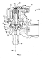
- Water about 20 includes a housing 22 having an inlet 24 and an outlet 26.
- a flow path extends between inlet 24 and outlet 26.
- a valve member assembly (see FIG. 3 ) is situated within the flow path and operable to open and close the same to allow or prevent fluid flow between inlet 24 and outlet 26 through water valve 20.
- Water valve 20 also includes a guide tube 30 which is laser welded to housing 22.
- Guide tube 30 is used to contain and armature 32 (See FIG. 2 ) which is biased within an internal bore of guide to 30 by a spring 34 (See FIG. 2 ).
- Spring 34 biases armature 32 against valve member assembly 28 to maintain water valve 20 in a closed position, i.e. position in which fluid flow between inlet 24 and outlet 26 is prevented.
- Water valve 20 also includes a solenoid actuator 36 attached to guide tube 30.
- Solenoid actuator 36 includes contacts 38 for an electrical connection. Current applied to solenoid actuator 36 via the electrical connection 38 causes armature 32 two move within guide tube 30 against the biasing force of spring 34 two transition water valve 20 from the closed position to an open position in which water is permitted to flow between inlet 24 and outlet 26.
- guide to 30 is laser welded to housing 22 to form a weld joint 44 on an exterior of water valve 20 at shown. Also as briefly introduced above, this use of laser welding advantageously allows for the omission of a spin ring unlike prior designs which utilize spin welding, and provides for enhanced perpendicularly and height tolerancing of guide to 30 relative to housing 22.
- housing 22 is threaded in the region of inlet 24 to allow for a threaded connection of an inlet supply line of water.
- Outlet 26 includes a hose barb style connection for connection of an outlet supply line for receiving a flow of water passing through water valve 20.
- housing 22 includes a single mounting boss 40 mounting for mounting water valve 20 in its operational environment.
- guide tube 30 includes a circular base 50 with an extension 52 depending upwardly from base 50. More specifically, base 50 extends between lower and upper surfaces 58, 60. Extension 52 extends upwardly from upper surface 60. An annular ring 54 extends downwardly from lower surface 58. As we described in greater detail below, lower surface 58 defines a first mating surface used to mate with a second mating surface 70 formed on housing 22. Each mating surface 58, 70 is an axially facing mating surface in that it is arranged in a plane which is perpendicular to a longitudinal axis 46 (See FIG. 1 ) of water vavle 20. With momentary reference to FIG. 1 , this longitudinal axis 46 extends through outlet 26 as well as the length of guide tube 30.
- a plurality of support ribs 62 are also formed on the upper surface 60 of base 50 and support guide tube 52 in its cantilevered extension. The number, shape, and extension of these ribs 62 may vary depending on the length of extension 52 and other factors. Additionally, a plurality of mounting tabs 64 extend from upper surface 60 of base 50. Mounting tabs 64 are used to hold solenoid actuator 36 against guide tube 30. In particular, mounting tabs 64 snap into corresponding slots 66 formed in the outer cage of solenoid actuator 36.
- valve member assembly 28 includes a flexible diaphragm 80 with a pilot member 82 mounted thereto.
- diaphragm 80 is movable within an internal chamber 72 of housing 22 to open and close water valve 20.
- Armature 32 acts against pilot member 82 to apply a downward force against thereto to seat diaphragm 80 against a valve seat 86 within internal cavity 72 of housing 22, as described below.
- solenoid actuator 36 is energized to move armature 32 upwardly within guide to 30, armature 32 no longer exerts a downward force against pilot member 82 (as well as diaphragm 80 via their connection) thereby exposing a pilot passageway 102 (see FIG. 3 ).
- water valve 20 is shown in a cross-section in the closed position.
- Amateur 32 is biased by spring 34 against pilot member 82 such that diaphragm 80 seemingly contacts valve seat 86.
- diaphragm 80 separates internal cavity 72 into an inlet cavity 90 and an outlet cavity 92 situated respectively on either side of diaphragm 80.
- water entering inlet 24 may proceed into inlet cavity 90.
- This water may then pass through diaphragm 80 by way of a plurality of passageways 94 formed through diaphragm 80.
- a passageway 96 (See FIG. 2 ) is formed through pilot member 82.
- water entering inlet 24 is in fluid communication with both inlet chamber 90 and outlet chamber 92.
- pilot number 82 moves upwardly with diaphragm 80 when transitioning from the closed position to the open position.
- mating surfaces 58 and 70 are axially abut. Additionally, an axial abutment surface 110 and a radial abutment surface 112 are brought into contact with diaphragm 80 to locate the same. A laser welding operation is then applied at the interface of mating surfaces 58, 70 to form a weld joint 44 at the exterior of water valve 20. As a result, a region of overlap W between mating surfaces 58, 70 is fused and becomes a contiguous material after welding.
- mating surface 70 may remain partially intact with the remainder thereof being fused with base 50 as described above.
- guide tube 30 out of an optically clear material.
- optically clear means a material which is optically clear to a laser, regardless of whether the same is clear to the human eye. Such material advantageously allows minimal to no diffusion of laser light which passes therethrough.
- housing 22 of an energy absorbent material such that the same is optimized for energy absorption during the laser welding process. This allows for the abrupt softening of the material in the region of second mating surface 70 of housing 22. Heat is then transferred to guide tube 30 in this region to melt a portion thereof and fuse these components together into the contiguous material described above.
- housing 22 could be natural in color or natural with colorant added. Further, housing 22 could also be natural in color with a carbon black material added. It will be recognized that all of the examples above have the advantage of providing an energy absorbing material which absorbs the laser energy as it passes through the optically clear material of guide tube 30.
- laser welding may be applied in a top-down manner such that the laser used in the laser welding process must first pass through guide tube 30 before reaching housing 22.
- laser welding could be performed in the radial direction in which the laser contacts base 30 and housing 22 simultaneously at the interface thereof.
- housing 22 is first provided by way of molding. However, it is also possible to form housing by way of additive manufacturing, or more traditional machining methods. Valve member assembly 28 is then situated within an internal cavity 72 of housing 22. Guide tube 30 is then situated against housing 22 such that the above described radial and axial abutment of annular ring 54 and diaphragm 80 is achieved, as well as the axial abutment of mating services 58, 70. Guide tube 30 is then laser welded to housing 22 to form weld joint 44 which is exposed on an exterior of water about 20. A solenoid actuator is then mounted to guide tube 30 as discussed above.
- a spin ring is not employed. Further, complex geometry on the housing and/or the guide to is not necessary to achieve the weld herein. Instead, simple flat surfaces which meet with one another are utilized. As a result, a highly efficient, low part count, low cost water valve is provided.
Landscapes
- Engineering & Computer Science (AREA)
- Mechanical Engineering (AREA)
- General Engineering & Computer Science (AREA)
- Physics & Mathematics (AREA)
- Optics & Photonics (AREA)
- Fluid Mechanics (AREA)
- Health & Medical Sciences (AREA)
- Electromagnetism (AREA)
- Toxicology (AREA)
- Plasma & Fusion (AREA)
- Magnetically Actuated Valves (AREA)
- Fluid-Driven Valves (AREA)
Claims (9)
- Une vanne d'eau (20), la vanne d'eau (20) comprenant:un boîtier (22) ayant une entrée (24) et une sortie (26) et un chemin d'écoulement s'étendant à travers le boîtier (22) entre l'entrée (24) et la sortie (26);un ensemble d'éléments de vanne (28) situé dans le chemin d'écoulement et opérable pour ouvrir et fermer sélectivement le chemin d'écoulement;un tube de guidage (30), le tube de guidage (30) étant monté sur le boîtier (22);un actionneur à solénoïde (36) monté sur le tube de guidage (30);dans lequel le tube de guidage (30) comprend une première surface d'accouplement (58) orientée axialement, disposée perpendiculairement à un axe longitudinal (46) du tube de guidage (30) et dans lequel le boîtier comprend une deuxième surface d'accouplement (70) orientée axialement, disposée perpendiculairement à un axe longitudinal du boîtier;dans lequel les première et deuxième surfaces d'accouplement (58, 70) orientées axialement sont en butée l'une contre l'autre dans une configuration pré-collée de la vanne d'eau (20);caractérisé en ce que le tube de guidage (30) et le boîtier (22) forment un joint (44) à la périphérie extérieure de la vanne d'eau (20) par une opération de soudage au laser à une interface des première et deuxième surfaces d'accouplement (58, 70) orientées axialement.
- La vanne d'eau selon la revendication 1, dans laquelle le tube de guidage (30) est constitué d'un matériau optiquement clair et le boîtier (22) est constitué d'un matériau absorbant l'énergie.
- La vanne d'eau selon la revendication 1, dans laquelle le tube de guidage (30) comprend une base (50) et une extension (52) s'étendant à partir de la base (50), la base (50) s'étendant entre une surface supérieure et une surface inférieure (58, 60), dans lequel la première surface d'accouplement (58) est fournie par la surface inférieure (58).
- La vanne d'eau selon la revendication 3, dans lequel le boîtier (20) comprend une ouverture, le tube de guidage (30) étant reçu dans l'ouverture, et dans lequel la deuxième surface d'accouplement (70) entoure l'ouverture, et/ou
dans lequel la base (50) définit un diamètre du tube de guidage (30), et dans lequel l'extension (52) définit une hauteur du tube de guidage (30), dans lequel le diamètre est au moins la moitié de la hauteur, et/ou
dans lequel une pluralité de nervures de renforcement (62) s'étendent à partir de la surface supérieure de la base et renforcent l'extension (52). - La vanne d'eau selon la revendication 3, dans lequel l'extension (52) s'étend à partir de la surface supérieure (60) de la base (50), et dans lequel une bague annulaire (54) s'étend à partir de la surface inférieure (58),
en particulier dans lequel l'ensemble d'éléments de vanne (28) comprend une membrane (80) et un élément pilote (82), l'élément pilote (82) étant monté sur la membrane (80), dans lequel la bague annulaire (54) est en butée radialement et axialement contre une partie périphérique de la membrane (80). - Procédé de fabrication d'une vanne d'eau (20), le procédé comprenant les étapes consistant à:fournir un boîtier (22) ayant une entrée (24) et une sortie (26) et un chemin d'écoulement s'étendant à travers le boîtier (22) entre l'entrée (24) et la sortie (26);placer un ensemble d'éléments de vanne (28) dans le chemin d'écoulement;installer un tube de guidage (30) sur le boîtier (22) en soudant au laser le tube de guidage (30) directement sur le boîtier (22); etmonter un actionneur à solénoïde (36) sur le tube de guidage;caractérisé en ce que l'étape d'installation du tube de guidage (30) comprend la mise en butée d'une première surface d'accouplement (58) orientée axialement, formée sur le tube de guidage (30), avec une deuxième surface d'accouplement (70) orientée axialement du boîtier (22) pour former une interface, dans lequel un joint (44) est formé à l'interface après le soudage au laser.
- Procédé selon la revendication 6, dans lequel l'étape de fourniture du boîtier (22) comprend la fourniture d'une surface d'accouplement (70) orientée axialement sur une périphérie supérieure du boîtier (22),
en particulier dans lequel l'étape de fourniture du boîtier (22) comprend la formation du boîtier (22) en utilisant un matériau absorbant l'énergie,
en particulier dans lequel l'étape de placement de l'ensemble d'éléments de vanne (28) dans le chemin d'écoulement comprend le placement d'une membrane (80) et d'un élément pilote (82) monté sur la membrane (80) dans une cavité interne (72) du boîtier (22). - Procédé selon la revendication 6, dans lequel l'étape d'installation comprend la fourniture du tube de guidage (30) formé avec un matériau optiquement clair et la fourniture du boîtier (22) formé avec un matériau absorbant l'énergie,
en particulier dans lequel l'étape d'installation comprend la direction d'un faisceau laser d'un soudeur laser à travers le matériau optiquement clair du tube de guidage (30) et dans le matériau absorbant l'énergie du boîtier (22). - Procédé selon la revendication 6, dans lequel l'étape d'installation comprend la formation du joint (44) de telle sorte que le joint (44) se trouve à une périphérie extérieure de la vanne d'eau (20).
Applications Claiming Priority (1)
| Application Number | Priority Date | Filing Date | Title |
|---|---|---|---|
| US15/474,605 US11112025B2 (en) | 2017-03-30 | 2017-03-30 | Water valve guide tube with integrated weld ring and water valve incorporating same |
Publications (3)
| Publication Number | Publication Date |
|---|---|
| EP3382247A1 EP3382247A1 (fr) | 2018-10-03 |
| EP3382247B1 true EP3382247B1 (fr) | 2020-12-16 |
| EP3382247B8 EP3382247B8 (fr) | 2021-03-24 |
Family
ID=61837677
Family Applications (1)
| Application Number | Title | Priority Date | Filing Date |
|---|---|---|---|
| EP18164928.6A Active EP3382247B8 (fr) | 2017-03-30 | 2018-03-29 | Tube de guidage de soupape d'eau comportant un anneau de soudure intégré et soupape d'eau l'incorporant |
Country Status (5)
| Country | Link |
|---|---|
| US (1) | US11112025B2 (fr) |
| EP (1) | EP3382247B8 (fr) |
| KR (1) | KR20180111654A (fr) |
| CN (1) | CN108692086B (fr) |
| DE (1) | DE202018106323U1 (fr) |
Families Citing this family (20)
| Publication number | Priority date | Publication date | Assignee | Title |
|---|---|---|---|---|
| JP6914044B2 (ja) * | 2017-01-31 | 2021-08-04 | 株式会社キッツエスシーティー | ダイヤフラムバルブ |
| US20180313463A1 (en) * | 2017-04-26 | 2018-11-01 | Robertshaw Controls Company | Pilot operated valve with extended insert |
| US20200173572A1 (en) * | 2018-11-30 | 2020-06-04 | Johnson Controls Technology Company | Unique bracket coupling for rotary valve |
| EP3671073A1 (fr) | 2018-12-20 | 2020-06-24 | Danfoss A/S | Soupape d'expansion électrique |
| EP3671070A1 (fr) | 2018-12-20 | 2020-06-24 | Danfoss A/S | Vanne, en particulier vanne d'expansion |
| EP3672030A1 (fr) * | 2018-12-20 | 2020-06-24 | Danfoss A/S | Soupape, en particulier une soupape d'expansion |
| US11015498B2 (en) | 2019-01-11 | 2021-05-25 | Dayco Ip Holdings, Llc | Crankcase ventilation system with a flow control device for on board diagnostics |
| EP3951226B1 (fr) * | 2019-03-29 | 2025-04-23 | Fujikoki Corporation | Électrovanne |
| JP7082375B2 (ja) * | 2019-07-18 | 2022-06-08 | 株式会社不二工機 | 流路切換弁 |
| US12202446B2 (en) * | 2019-09-12 | 2025-01-21 | A. Raymond Et Cie | Flow control valve and system for cleaning a vehicle surface |
| US11692724B2 (en) | 2020-04-30 | 2023-07-04 | Johnson Controls Tyco IP Holdings LLP | Smart actuator with fault detection and resolution |
| KR102417555B1 (ko) * | 2020-11-06 | 2022-07-06 | 현대자동차주식회사 | 워셔액 공급 밸브 |
| US20230023051A1 (en) * | 2021-07-26 | 2023-01-26 | Ken Bergbauer | Acetal (POM) Water Valve |
| IT202100025658A1 (it) * | 2021-10-07 | 2023-04-07 | Bitron Spa | Elemento tubolare per valvole elettromagnetiche e relativa valvola elettromagnetica. |
| US11920689B2 (en) * | 2022-01-11 | 2024-03-05 | Samsung Electronics Co., Ltd. | Loose type pneumatic valve and loose type pneumatic valve module including the same |
| KR102623687B1 (ko) * | 2022-07-15 | 2024-01-11 | 우성알앤디주식회사 | 전자 급수 밸브의 결합 구조 |
| US12366869B2 (en) | 2023-03-13 | 2025-07-22 | Robertshaw Controls Company | Pressure sensing valve |
| EP4502442A1 (fr) * | 2023-08-04 | 2025-02-05 | Yuan Mei Corp. | Structure de pipeline anti-blocage avec soupape |
| US12492758B2 (en) * | 2023-08-04 | 2025-12-09 | Yuan Mei Corp. | Anti-blockage pipeline structure with valve |
| EP4575285A1 (fr) * | 2023-12-21 | 2025-06-25 | Yuan Mei Corp. | Structure de conduite avec vanne |
Family Cites Families (101)
| Publication number | Priority date | Publication date | Assignee | Title |
|---|---|---|---|---|
| US2160117A (en) | 1937-01-11 | 1939-05-30 | Nicostat Products Inc | Fluid control valve |
| US2228588A (en) | 1938-10-21 | 1941-01-14 | William A Ray | Fuel control valve |
| US2215954A (en) | 1939-05-26 | 1940-09-24 | Nicolstat Products Co | Fluid flow control device |
| US2398452A (en) | 1942-03-17 | 1946-04-16 | Penn Electric Switch Co | Three-way solenoid valve |
| US2549188A (en) | 1945-11-10 | 1951-04-17 | Raymond C Forsnas | Fluid flow control valve |
| US2430107A (en) | 1945-12-22 | 1947-11-04 | Cronrath Paul | Trundle truck |
| US2956770A (en) | 1956-03-09 | 1960-10-18 | American Radiator & Standard | Valve |
| US3090592A (en) | 1959-05-18 | 1963-05-21 | White Rodgers Company | Stepped-opening diaphragm gas valve |
| US3082359A (en) | 1960-01-26 | 1963-03-19 | Peter Paul Electronics Company | Solenoid and valve assembly |
| US3263693A (en) | 1964-12-31 | 1966-08-02 | Honeywell Inc | Pilot control valve and method of making same |
| US3410301A (en) | 1966-09-22 | 1968-11-12 | Richdel | Solenoid or timer operated pilot valve for main valve control |
| FR1513478A (fr) | 1967-01-02 | 1968-02-16 | Perfectionnements aux électro-vannes commandant le circuit d'un fluide | |
| US3603559A (en) | 1969-02-14 | 1971-09-07 | Cornelius Co | Solenoid-actuated valve mechanism with lever-type operating means |
| US3639870A (en) | 1970-07-10 | 1972-02-01 | Reginald B G Benson | Electromagnetic devices |
| US3818398A (en) | 1971-11-30 | 1974-06-18 | Sporlan Valve Co | Electromagnet coil assembly |
| US4088975A (en) | 1972-01-03 | 1978-05-09 | Lang Gregor L | Alternating current solenoids |
| JPS52122921A (en) | 1976-04-08 | 1977-10-15 | Matsushita Electric Industrial Co Ltd | Fluid control equipment |
| JPS595152Y2 (ja) | 1978-07-25 | 1984-02-16 | アイシン精機株式会社 | 集積型バルブセツト装置 |
| US4268009A (en) | 1979-06-06 | 1981-05-19 | Peter Paul Electronics | Solenoid valve |
| US4376447A (en) * | 1979-08-20 | 1983-03-15 | Umc Industries, Inc. | Hot water valve |
| US4443775A (en) | 1981-01-31 | 1984-04-17 | Shoketsu Kinzoku Kogyo Kabushiki Kaisha | Solenoid actuator |
| DE3108693A1 (de) | 1981-03-07 | 1982-09-23 | Walter Ing.(grad.) 7758 Meersburg Holzer | Elektromagnetventil, insbesondere fuer hausgeraete |
| US4441521A (en) | 1981-05-13 | 1984-04-10 | Eaton Corporation | Appliance control valve assembly with opposite magnetic polarity solenoid coils |
| US4418888A (en) | 1981-06-08 | 1983-12-06 | Perfection Corporation | Angle cock valve |
| US4534537A (en) | 1981-07-13 | 1985-08-13 | Eaton Corporation | Pilot operated valve assembly |
| US4387878A (en) | 1981-07-13 | 1983-06-14 | Eaton Corporation | Pilot operated valve assembly |
| JPS5828077A (ja) | 1981-08-07 | 1983-02-18 | Aisin Seiki Co Ltd | 調圧バルブ装置 |
| US4483672A (en) | 1983-01-19 | 1984-11-20 | Essex Group, Inc. | Gas burner control system |
| US4500067A (en) | 1983-02-07 | 1985-02-19 | Eaton Corporation | Pilot operated low flow valve |
| US4635494A (en) | 1983-10-03 | 1987-01-13 | Conklin Emmett D | Infinitely variable transmission and control apparatus therefor |
| US4502661A (en) | 1983-11-04 | 1985-03-05 | Eaton Corporation | Electrically actuated valve assembly |
| JPH0632536Y2 (ja) | 1987-02-10 | 1994-08-24 | 株式会社ユニシアジェックス | 電磁弁 |
| DE3739048C2 (de) | 1987-11-17 | 2001-08-09 | Buerkert Gmbh | Mehrwegeventil |
| US4981155A (en) | 1988-09-30 | 1991-01-01 | Eaton Corporation | Electrically operated valve assembly |
| US4884782A (en) | 1989-04-14 | 1989-12-05 | Siemens-Bendix Automotive Electronics L.P. | Means for separably attaching solenoid to valve |
| US4958774A (en) | 1989-06-21 | 1990-09-25 | General Motors Corporation | Fuel injection |
| US5090441A (en) | 1991-01-16 | 1992-02-25 | Emerson Electric Co. | Anti-clog valve |
| US5145145A (en) | 1991-03-11 | 1992-09-08 | Eaton Corporation | Pilot operated electrically actuated value assembly |
| DE4112463A1 (de) | 1991-04-12 | 1992-10-15 | Mannesmann Ag | Ventilanordnung fuer druckmedien |
| US5140876A (en) | 1992-03-02 | 1992-08-25 | Fields Walter G | Variable-fulcrum pliers |
| US5269333A (en) | 1993-04-22 | 1993-12-14 | Emerson Electric Co. | Anti-clog water valve |
| DE4326838C2 (de) | 1993-08-10 | 1996-01-11 | Interelektrik Ges M B H & Co K | Bistabiles Magnetventil |
| US5599033A (en) | 1993-08-30 | 1997-02-04 | Tri Industries, Inc. | Convertible trailer and jogging stroller for two children |
| WO1995014874A1 (fr) | 1993-11-24 | 1995-06-01 | Goyen Controls Co. Pty. Limited | Membrane prenant spontanement une position dans une soupape |
| US5403230A (en) | 1993-12-20 | 1995-04-04 | Capriglione, Sr.; Anthony | Shellfish claw cutter |
| JPH07198058A (ja) | 1993-12-28 | 1995-08-01 | Nakagawa Electric Ind Co Ltd | パイロット電磁弁 |
| US5435519A (en) | 1994-03-31 | 1995-07-25 | Stemens Electric Limited | EGR system having fast-acting EGR valve |
| DE4425540C2 (de) | 1994-07-19 | 2003-05-22 | Buerkert Werke Gmbh & Co | Modulares Ventil für strömende Medien |
| US5709370A (en) | 1995-04-10 | 1998-01-20 | Kah, Jr.; Carl L. C. | Magnetically actuated valve |
| US6076550A (en) | 1995-09-08 | 2000-06-20 | Toto Ltd. | Solenoid and solenoid valve |
| DE19534285A1 (de) | 1995-09-15 | 1997-03-20 | Bosch Gmbh Robert | Elektromagnetisch betätigbares pneumatisches Wegeventil |
| US5674002A (en) | 1995-11-27 | 1997-10-07 | Powell; Talmadge Wayne | Hammers with optimal claw shape and method for development of optimally designed hammers, crowbars, and levers |
| CN1153876A (zh) | 1996-01-05 | 1997-07-09 | 基步驰贸易公司 | 阀装置 |
| DE19622626A1 (de) * | 1996-06-05 | 1997-12-11 | Interelektrik Ges M B H & Co K | Magnetventil |
| US5954311A (en) | 1996-07-19 | 1999-09-21 | Nu-Valve Pty Ltd | Low power pilot valve actuated by transverse or perpendicular action |
| US5808534A (en) | 1996-07-30 | 1998-09-15 | Laffey; James | Solenoid frame and method of manufacture |
| US5941502A (en) | 1996-10-31 | 1999-08-24 | Cooper; Robert J. | Electric valve assembly and method of making same |
| CA2262944A1 (fr) | 1997-06-20 | 2000-08-24 | Gilbert A. Hice | Systeme et methode de levier pour les pieds |
| US5921009A (en) | 1997-06-20 | 1999-07-13 | Pivotal Image, Inc. | Foot leverage system and method |
| JPH11294619A (ja) | 1998-04-06 | 1999-10-29 | Techno Excel Co Ltd | 常開形パイロット式電磁弁 |
| US6014917A (en) | 1998-07-01 | 2000-01-18 | B!G Ventures, L.L.C. | Self-adjusting and/or self-locking pliers |
| DE19832826C2 (de) | 1998-07-21 | 2000-08-17 | Bosch Gmbh Robert | Montageverfahren für Kraftstoff-Einspritzventil und Vorsteuerventil sowie Kraftstoff-Einspritzventil |
| DE19846841C2 (de) | 1998-10-12 | 2002-06-20 | I E M Ind Entwicklung Medizint | Elektromagnetisches Ventil |
| JP3749026B2 (ja) | 1998-11-27 | 2006-02-22 | 三菱電機株式会社 | ソレノイドバルブの固定装置 |
| US6149124A (en) | 1999-05-03 | 2000-11-21 | Husco International, Inc. | Pilot solenoid control valve with pressure responsive diaphragm |
| DE19958913A1 (de) | 1999-12-07 | 2001-06-28 | Bosch Gmbh Robert | Elektromagnetisch betätigbares Ventil |
| US6318213B1 (en) | 2000-01-07 | 2001-11-20 | Ralph Dann Hendrix | Roofers shingle removal tool |
| JP3662159B2 (ja) | 2000-02-16 | 2005-06-22 | 株式会社テージーケー | ソレノイド駆動パイロット弁 |
| JP2001235051A (ja) | 2000-02-23 | 2001-08-31 | Techno Excel Co Ltd | 電磁式給水弁 |
| US6374814B1 (en) | 2000-09-28 | 2002-04-23 | Siemens Canada Limited | Electric exhaust gas recirculation valve with integral position sensor and method of making |
| US7226393B2 (en) | 2001-01-19 | 2007-06-05 | Nautilus, Inc. | Exercise bicycle |
| US6591797B2 (en) | 2001-03-23 | 2003-07-15 | William W. Entzminger | Variable fulcrum rocker arm |
| US6439214B1 (en) * | 2001-08-14 | 2002-08-27 | Siemens Automotive Inc. | Linear solenoid automotive emission control valve |
| US6684901B1 (en) | 2001-08-23 | 2004-02-03 | Deltrol Controls | Modular liquid dispensing valve |
| US6820621B2 (en) | 2002-03-22 | 2004-11-23 | Imp Inc. | Lateral surgical positioner unit |
| EP1350999B1 (fr) | 2002-03-28 | 2006-08-02 | Fluid Automation Systems S.A. | Vanne électromagnétique |
| JP4090845B2 (ja) | 2002-10-31 | 2008-05-28 | シナノケンシ株式会社 | ソレノイド |
| US6870454B1 (en) | 2003-09-08 | 2005-03-22 | Com Dev Ltd. | Linear switch actuator |
| US7309303B1 (en) | 2004-01-14 | 2007-12-18 | Richard Proctor | Exercising and physiotherapy system |
| US7111444B1 (en) | 2004-02-20 | 2006-09-26 | Morris Larry D | Lawn tractor lift |
| JP4366297B2 (ja) * | 2004-11-30 | 2009-11-18 | 株式会社ケーヒン | 燃料電池用電磁弁 |
| DE102005049123A1 (de) | 2005-04-13 | 2006-10-19 | Continental Teves Ag & Co. Ohg | Elektromagnetventil |
| US7226034B2 (en) | 2005-09-27 | 2007-06-05 | Emerson Electric Co. | Solenoid valve actuator |
| US7341236B2 (en) | 2006-03-07 | 2008-03-11 | Husco International, Inc. | Pilot operated valve with a pressure balanced poppet |
| EP2069667B1 (fr) | 2006-09-26 | 2016-02-17 | Fluid Automation Systems S.A. | Soupape à champignon |
| ES1064806Y (es) | 2007-01-31 | 2007-08-01 | Orkli S Coop Ltda | Valvula electromagnetica auxiliar para una servovalvula de gas |
| WO2009006684A1 (fr) | 2007-07-11 | 2009-01-15 | Microflow International Pty Limited | Soupape |
| DE202007012652U1 (de) | 2007-09-10 | 2007-11-22 | Bürkert Werke GmbH & Co. KG | Magnetventil |
| US8267375B1 (en) | 2007-10-01 | 2012-09-18 | Numatics, Incorporated | Cartridge valve and manifold assembly |
| KR100964254B1 (ko) | 2008-03-06 | 2010-06-16 | 우성전기공업 주식회사 | 전자석 급수밸브 |
| TW200938756A (en) | 2008-03-14 | 2009-09-16 | Delta Electronics Inc | Solenoid valve |
| US20100019179A1 (en) | 2008-07-24 | 2010-01-28 | Robertshaw Controls Company | Solenoid for a Pilot Operated Water Valve Having Reduced Copper and Increased Thermal Efficiency |
| JP4725813B2 (ja) | 2008-10-07 | 2011-07-13 | 株式会社デンソー | 樹脂成形品 |
| DE102009058165A1 (de) | 2009-12-15 | 2011-06-16 | Svm Schultz Verwaltungs-Gmbh & Co. Kg | Magnetantrieb |
| US20120153199A1 (en) | 2010-12-20 | 2012-06-21 | Robertshaw Controls Company | Solenoid for a Direct Acting Valve Having Stepped Guide Tube |
| US10544874B2 (en) | 2011-01-04 | 2020-01-28 | Robertshaw Controls Company | Coil capture apparatus and pilot operated water valve incorporating same |
| DE102011010181A1 (de) | 2011-02-02 | 2012-08-02 | Pierburg Gmbh | Werkstückteil, insbesondere für Gehäuseanordnungen sowie Verfahren zum Verbinden mittels Laserstrahlen von Werkstückteilen |
| JP6059509B2 (ja) | 2011-12-12 | 2017-01-11 | Ckd株式会社 | 流体制御弁 |
| JP6021551B2 (ja) * | 2012-09-26 | 2016-11-09 | 株式会社不二工機 | 電磁弁 |
| JP2014177051A (ja) | 2013-03-15 | 2014-09-25 | Denso Corp | 溶着体のレーザー溶着方法 |
| JP6565403B2 (ja) | 2015-07-15 | 2019-08-28 | 浜名湖電装株式会社 | 樹脂成形品の製造方法 |
-
2017
- 2017-03-30 US US15/474,605 patent/US11112025B2/en active Active
-
2018
- 2018-03-29 CN CN201810273602.2A patent/CN108692086B/zh active Active
- 2018-03-29 DE DE202018106323.5U patent/DE202018106323U1/de active Active
- 2018-03-29 KR KR1020180036743A patent/KR20180111654A/ko not_active Ceased
- 2018-03-29 EP EP18164928.6A patent/EP3382247B8/fr active Active
Non-Patent Citations (1)
| Title |
|---|
| None * |
Also Published As
| Publication number | Publication date |
|---|---|
| EP3382247A1 (fr) | 2018-10-03 |
| US20180283572A1 (en) | 2018-10-04 |
| KR20180111654A (ko) | 2018-10-11 |
| EP3382247B8 (fr) | 2021-03-24 |
| CN108692086B (zh) | 2022-04-29 |
| US11112025B2 (en) | 2021-09-07 |
| CN108692086A (zh) | 2018-10-23 |
| DE202018106323U1 (de) | 2018-11-21 |
Similar Documents
| Publication | Publication Date | Title |
|---|---|---|
| EP3382247B1 (fr) | Tube de guidage de soupape d'eau comportant un anneau de soudure intégré et soupape d'eau l'incorporant | |
| EP3608566B1 (fr) | Élément de diaphragme et soupape à diaphragme doté d'un élément de diaphragme | |
| EP2713085B1 (fr) | Vanne à solénoïde | |
| EP3315835A1 (fr) | Soupape électrique et son procédé d'assemblage | |
| JP7722741B2 (ja) | 電動弁 | |
| US20170114916A1 (en) | Solenoid valve device | |
| EP2568481B1 (fr) | Unité de commande électromagnétique et procédé de production de celle-ci | |
| JP2015510276A (ja) | 相互結合部を備えた磁束コレクタ及びこれを含む電磁弁アセンブリの製造方法 | |
| JP6308685B2 (ja) | 通電閉型電磁弁の製造方法及び通電閉型電磁弁 | |
| EP3117980A1 (fr) | Produit moulé en plastique et son procédé de fabrication | |
| US9772045B2 (en) | Valve cartridge | |
| JP6542447B1 (ja) | 樹脂パイプと樹脂部材との接合方法および接合構造 | |
| JP2017082815A (ja) | 電磁弁装置とその製造方法 | |
| JP6940155B2 (ja) | ダイヤフラム部材を用いるダイヤフラム弁 | |
| KR20030063187A (ko) | 솔레노이드 작동식 가변 유출 압력 제어 밸브 및 그 내의자동 입구 차단부 제공 방법 | |
| US7222642B2 (en) | Enhanced water valve tube stop | |
| JP3930478B2 (ja) | 管継手 | |
| CN114667422B (zh) | 动力元件以及使用了该动力元件的膨胀阀 | |
| CN114667423B (zh) | 动力元件以及使用了该动力元件的膨胀阀 | |
| CN112576797B (zh) | 一种电动阀 | |
| CN111237525A (zh) | 电子膨胀阀及其组装方法 | |
| JP5075555B2 (ja) | 弁装置用の合成樹脂ハウジング | |
| CN216692371U (zh) | 一种电磁阀 | |
| JP6446172B2 (ja) | 電磁弁 | |
| EP4119826A1 (fr) | Électrovanne |
Legal Events
| Date | Code | Title | Description |
|---|---|---|---|
| REG | Reference to a national code |
Ref country code: DE Ref legal event code: R138 Ref document number: 202018106323 Country of ref document: DE Free format text: GERMAN DOCUMENT NUMBER IS 602018010752 |
|
| PUAI | Public reference made under article 153(3) epc to a published international application that has entered the european phase |
Free format text: ORIGINAL CODE: 0009012 |
|
| STAA | Information on the status of an ep patent application or granted ep patent |
Free format text: STATUS: THE APPLICATION HAS BEEN PUBLISHED |
|
| AK | Designated contracting states |
Kind code of ref document: A1 Designated state(s): AL AT BE BG CH CY CZ DE DK EE ES FI FR GB GR HR HU IE IS IT LI LT LU LV MC MK MT NL NO PL PT RO RS SE SI SK SM TR |
|
| AX | Request for extension of the european patent |
Extension state: BA ME |
|
| STAA | Information on the status of an ep patent application or granted ep patent |
Free format text: STATUS: REQUEST FOR EXAMINATION WAS MADE |
|
| 17P | Request for examination filed |
Effective date: 20190403 |
|
| RBV | Designated contracting states (corrected) |
Designated state(s): AL AT BE BG CH CY CZ DE DK EE ES FI FR GB GR HR HU IE IS IT LI LT LU LV MC MK MT NL NO PL PT RO RS SE SI SK SM TR |
|
| STAA | Information on the status of an ep patent application or granted ep patent |
Free format text: STATUS: EXAMINATION IS IN PROGRESS |
|
| 17Q | First examination report despatched |
Effective date: 20190702 |
|
| GRAP | Despatch of communication of intention to grant a patent |
Free format text: ORIGINAL CODE: EPIDOSNIGR1 |
|
| STAA | Information on the status of an ep patent application or granted ep patent |
Free format text: STATUS: GRANT OF PATENT IS INTENDED |
|
| INTG | Intention to grant announced |
Effective date: 20200715 |
|
| RAP1 | Party data changed (applicant data changed or rights of an application transferred) |
Owner name: ROBERTSHAW CONTROL COMPANY |
|
| GRAS | Grant fee paid |
Free format text: ORIGINAL CODE: EPIDOSNIGR3 |
|
| GRAA | (expected) grant |
Free format text: ORIGINAL CODE: 0009210 |
|
| STAA | Information on the status of an ep patent application or granted ep patent |
Free format text: STATUS: THE PATENT HAS BEEN GRANTED |
|
| AK | Designated contracting states |
Kind code of ref document: B1 Designated state(s): AL AT BE BG CH CY CZ DE DK EE ES FI FR GB GR HR HU IE IS IT LI LT LU LV MC MK MT NL NO PL PT RO RS SE SI SK SM TR |
|
| REG | Reference to a national code |
Ref country code: GB Ref legal event code: FG4D |
|
| REG | Reference to a national code |
Ref country code: IE Ref legal event code: FG4D |
|
| REG | Reference to a national code |
Ref country code: DE Ref legal event code: R096 Ref document number: 602018010752 Country of ref document: DE |
|
| REG | Reference to a national code |
Ref country code: AT Ref legal event code: REF Ref document number: 1345906 Country of ref document: AT Kind code of ref document: T Effective date: 20210115 |
|
| GRAT | Correction requested after decision to grant or after decision to maintain patent in amended form |
Free format text: ORIGINAL CODE: EPIDOSNCDEC |
|
| REG | Reference to a national code |
Ref country code: CH Ref legal event code: PK Free format text: BERICHTIGUNG B8 |
|
| RAP2 | Party data changed (patent owner data changed or rights of a patent transferred) |
Owner name: ROBERTSHAW CONTROLS COMPANY |
|
| PG25 | Lapsed in a contracting state [announced via postgrant information from national office to epo] |
Ref country code: RS Free format text: LAPSE BECAUSE OF FAILURE TO SUBMIT A TRANSLATION OF THE DESCRIPTION OR TO PAY THE FEE WITHIN THE PRESCRIBED TIME-LIMIT Effective date: 20201216 Ref country code: FI Free format text: LAPSE BECAUSE OF FAILURE TO SUBMIT A TRANSLATION OF THE DESCRIPTION OR TO PAY THE FEE WITHIN THE PRESCRIBED TIME-LIMIT Effective date: 20201216 Ref country code: NO Free format text: LAPSE BECAUSE OF FAILURE TO SUBMIT A TRANSLATION OF THE DESCRIPTION OR TO PAY THE FEE WITHIN THE PRESCRIBED TIME-LIMIT Effective date: 20210316 Ref country code: GR Free format text: LAPSE BECAUSE OF FAILURE TO SUBMIT A TRANSLATION OF THE DESCRIPTION OR TO PAY THE FEE WITHIN THE PRESCRIBED TIME-LIMIT Effective date: 20210317 |
|
| REG | Reference to a national code |
Ref country code: AT Ref legal event code: MK05 Ref document number: 1345906 Country of ref document: AT Kind code of ref document: T Effective date: 20201216 |
|
| REG | Reference to a national code |
Ref country code: NL Ref legal event code: MP Effective date: 20201216 |
|
| PG25 | Lapsed in a contracting state [announced via postgrant information from national office to epo] |
Ref country code: BG Free format text: LAPSE BECAUSE OF FAILURE TO SUBMIT A TRANSLATION OF THE DESCRIPTION OR TO PAY THE FEE WITHIN THE PRESCRIBED TIME-LIMIT Effective date: 20210316 Ref country code: LV Free format text: LAPSE BECAUSE OF FAILURE TO SUBMIT A TRANSLATION OF THE DESCRIPTION OR TO PAY THE FEE WITHIN THE PRESCRIBED TIME-LIMIT Effective date: 20201216 Ref country code: SE Free format text: LAPSE BECAUSE OF FAILURE TO SUBMIT A TRANSLATION OF THE DESCRIPTION OR TO PAY THE FEE WITHIN THE PRESCRIBED TIME-LIMIT Effective date: 20201216 |
|
| PG25 | Lapsed in a contracting state [announced via postgrant information from national office to epo] |
Ref country code: HR Free format text: LAPSE BECAUSE OF FAILURE TO SUBMIT A TRANSLATION OF THE DESCRIPTION OR TO PAY THE FEE WITHIN THE PRESCRIBED TIME-LIMIT Effective date: 20201216 Ref country code: NL Free format text: LAPSE BECAUSE OF FAILURE TO SUBMIT A TRANSLATION OF THE DESCRIPTION OR TO PAY THE FEE WITHIN THE PRESCRIBED TIME-LIMIT Effective date: 20201216 |
|
| REG | Reference to a national code |
Ref country code: LT Ref legal event code: MG9D |
|
| PG25 | Lapsed in a contracting state [announced via postgrant information from national office to epo] |
Ref country code: SM Free format text: LAPSE BECAUSE OF FAILURE TO SUBMIT A TRANSLATION OF THE DESCRIPTION OR TO PAY THE FEE WITHIN THE PRESCRIBED TIME-LIMIT Effective date: 20201216 Ref country code: EE Free format text: LAPSE BECAUSE OF FAILURE TO SUBMIT A TRANSLATION OF THE DESCRIPTION OR TO PAY THE FEE WITHIN THE PRESCRIBED TIME-LIMIT Effective date: 20201216 Ref country code: CZ Free format text: LAPSE BECAUSE OF FAILURE TO SUBMIT A TRANSLATION OF THE DESCRIPTION OR TO PAY THE FEE WITHIN THE PRESCRIBED TIME-LIMIT Effective date: 20201216 Ref country code: RO Free format text: LAPSE BECAUSE OF FAILURE TO SUBMIT A TRANSLATION OF THE DESCRIPTION OR TO PAY THE FEE WITHIN THE PRESCRIBED TIME-LIMIT Effective date: 20201216 Ref country code: SK Free format text: LAPSE BECAUSE OF FAILURE TO SUBMIT A TRANSLATION OF THE DESCRIPTION OR TO PAY THE FEE WITHIN THE PRESCRIBED TIME-LIMIT Effective date: 20201216 Ref country code: PT Free format text: LAPSE BECAUSE OF FAILURE TO SUBMIT A TRANSLATION OF THE DESCRIPTION OR TO PAY THE FEE WITHIN THE PRESCRIBED TIME-LIMIT Effective date: 20210416 Ref country code: LT Free format text: LAPSE BECAUSE OF FAILURE TO SUBMIT A TRANSLATION OF THE DESCRIPTION OR TO PAY THE FEE WITHIN THE PRESCRIBED TIME-LIMIT Effective date: 20201216 |
|
| PG25 | Lapsed in a contracting state [announced via postgrant information from national office to epo] |
Ref country code: AT Free format text: LAPSE BECAUSE OF FAILURE TO SUBMIT A TRANSLATION OF THE DESCRIPTION OR TO PAY THE FEE WITHIN THE PRESCRIBED TIME-LIMIT Effective date: 20201216 Ref country code: PL Free format text: LAPSE BECAUSE OF FAILURE TO SUBMIT A TRANSLATION OF THE DESCRIPTION OR TO PAY THE FEE WITHIN THE PRESCRIBED TIME-LIMIT Effective date: 20201216 |
|
| REG | Reference to a national code |
Ref country code: DE Ref legal event code: R097 Ref document number: 602018010752 Country of ref document: DE |
|
| PG25 | Lapsed in a contracting state [announced via postgrant information from national office to epo] |
Ref country code: IS Free format text: LAPSE BECAUSE OF FAILURE TO SUBMIT A TRANSLATION OF THE DESCRIPTION OR TO PAY THE FEE WITHIN THE PRESCRIBED TIME-LIMIT Effective date: 20210416 |
|
| PLBE | No opposition filed within time limit |
Free format text: ORIGINAL CODE: 0009261 |
|
| STAA | Information on the status of an ep patent application or granted ep patent |
Free format text: STATUS: NO OPPOSITION FILED WITHIN TIME LIMIT |
|
| PG25 | Lapsed in a contracting state [announced via postgrant information from national office to epo] |
Ref country code: MC Free format text: LAPSE BECAUSE OF FAILURE TO SUBMIT A TRANSLATION OF THE DESCRIPTION OR TO PAY THE FEE WITHIN THE PRESCRIBED TIME-LIMIT Effective date: 20201216 Ref country code: AL Free format text: LAPSE BECAUSE OF FAILURE TO SUBMIT A TRANSLATION OF THE DESCRIPTION OR TO PAY THE FEE WITHIN THE PRESCRIBED TIME-LIMIT Effective date: 20201216 |
|
| REG | Reference to a national code |
Ref country code: CH Ref legal event code: PL |
|
| 26N | No opposition filed |
Effective date: 20210917 |
|
| PG25 | Lapsed in a contracting state [announced via postgrant information from national office to epo] |
Ref country code: DK Free format text: LAPSE BECAUSE OF FAILURE TO SUBMIT A TRANSLATION OF THE DESCRIPTION OR TO PAY THE FEE WITHIN THE PRESCRIBED TIME-LIMIT Effective date: 20201216 |
|
| REG | Reference to a national code |
Ref country code: BE Ref legal event code: MM Effective date: 20210331 |
|
| PG25 | Lapsed in a contracting state [announced via postgrant information from national office to epo] |
Ref country code: FR Free format text: LAPSE BECAUSE OF NON-PAYMENT OF DUE FEES Effective date: 20210331 Ref country code: ES Free format text: LAPSE BECAUSE OF FAILURE TO SUBMIT A TRANSLATION OF THE DESCRIPTION OR TO PAY THE FEE WITHIN THE PRESCRIBED TIME-LIMIT Effective date: 20201216 Ref country code: CH Free format text: LAPSE BECAUSE OF NON-PAYMENT OF DUE FEES Effective date: 20210331 Ref country code: LU Free format text: LAPSE BECAUSE OF NON-PAYMENT OF DUE FEES Effective date: 20210329 Ref country code: LI Free format text: LAPSE BECAUSE OF NON-PAYMENT OF DUE FEES Effective date: 20210331 Ref country code: IE Free format text: LAPSE BECAUSE OF NON-PAYMENT OF DUE FEES Effective date: 20210329 |
|
| PG25 | Lapsed in a contracting state [announced via postgrant information from national office to epo] |
Ref country code: SI Free format text: LAPSE BECAUSE OF FAILURE TO SUBMIT A TRANSLATION OF THE DESCRIPTION OR TO PAY THE FEE WITHIN THE PRESCRIBED TIME-LIMIT Effective date: 20201216 |
|
| PG25 | Lapsed in a contracting state [announced via postgrant information from national office to epo] |
Ref country code: IS Free format text: LAPSE BECAUSE OF FAILURE TO SUBMIT A TRANSLATION OF THE DESCRIPTION OR TO PAY THE FEE WITHIN THE PRESCRIBED TIME-LIMIT Effective date: 20210416 |
|
| PG25 | Lapsed in a contracting state [announced via postgrant information from national office to epo] |
Ref country code: BE Free format text: LAPSE BECAUSE OF NON-PAYMENT OF DUE FEES Effective date: 20210331 |
|
| PG25 | Lapsed in a contracting state [announced via postgrant information from national office to epo] |
Ref country code: CY Free format text: LAPSE BECAUSE OF FAILURE TO SUBMIT A TRANSLATION OF THE DESCRIPTION OR TO PAY THE FEE WITHIN THE PRESCRIBED TIME-LIMIT Effective date: 20201216 |
|
| PG25 | Lapsed in a contracting state [announced via postgrant information from national office to epo] |
Ref country code: HU Free format text: LAPSE BECAUSE OF FAILURE TO SUBMIT A TRANSLATION OF THE DESCRIPTION OR TO PAY THE FEE WITHIN THE PRESCRIBED TIME-LIMIT; INVALID AB INITIO Effective date: 20180329 |
|
| PG25 | Lapsed in a contracting state [announced via postgrant information from national office to epo] |
Ref country code: MK Free format text: LAPSE BECAUSE OF FAILURE TO SUBMIT A TRANSLATION OF THE DESCRIPTION OR TO PAY THE FEE WITHIN THE PRESCRIBED TIME-LIMIT Effective date: 20201216 |
|
| PG25 | Lapsed in a contracting state [announced via postgrant information from national office to epo] |
Ref country code: MT Free format text: LAPSE BECAUSE OF FAILURE TO SUBMIT A TRANSLATION OF THE DESCRIPTION OR TO PAY THE FEE WITHIN THE PRESCRIBED TIME-LIMIT Effective date: 20201216 |
|
| PG25 | Lapsed in a contracting state [announced via postgrant information from national office to epo] |
Ref country code: TR Free format text: LAPSE BECAUSE OF FAILURE TO SUBMIT A TRANSLATION OF THE DESCRIPTION OR TO PAY THE FEE WITHIN THE PRESCRIBED TIME-LIMIT Effective date: 20201216 |
|
| PGFP | Annual fee paid to national office [announced via postgrant information from national office to epo] |
Ref country code: GB Payment date: 20260106 Year of fee payment: 9 |
|
| PGFP | Annual fee paid to national office [announced via postgrant information from national office to epo] |
Ref country code: DE Payment date: 20260102 Year of fee payment: 9 |
|
| PGFP | Annual fee paid to national office [announced via postgrant information from national office to epo] |
Ref country code: IT Payment date: 20260220 Year of fee payment: 9 |