EP3382251A2 - Tuyau fluidique pourvu d'un bourrelet d'épaississement entourant - Google Patents
Tuyau fluidique pourvu d'un bourrelet d'épaississement entourant Download PDFInfo
- Publication number
- EP3382251A2 EP3382251A2 EP18162695.3A EP18162695A EP3382251A2 EP 3382251 A2 EP3382251 A2 EP 3382251A2 EP 18162695 A EP18162695 A EP 18162695A EP 3382251 A2 EP3382251 A2 EP 3382251A2
- Authority
- EP
- European Patent Office
- Prior art keywords
- fluid
- tube
- fluid tube
- circumferential thickening
- hose
- Prior art date
- Legal status (The legal status is an assumption and is not a legal conclusion. Google has not performed a legal analysis and makes no representation as to the accuracy of the status listed.)
- Granted
Links
Images


Classifications
-
- F—MECHANICAL ENGINEERING; LIGHTING; HEATING; WEAPONS; BLASTING
- F16—ENGINEERING ELEMENTS AND UNITS; GENERAL MEASURES FOR PRODUCING AND MAINTAINING EFFECTIVE FUNCTIONING OF MACHINES OR INSTALLATIONS; THERMAL INSULATION IN GENERAL
- F16L—PIPES; JOINTS OR FITTINGS FOR PIPES; SUPPORTS FOR PIPES, CABLES OR PROTECTIVE TUBING; MEANS FOR THERMAL INSULATION IN GENERAL
- F16L11/00—Hoses, i.e. flexible pipes
- F16L11/04—Hoses, i.e. flexible pipes made of rubber or flexible plastics
- F16L11/11—Hoses, i.e. flexible pipes made of rubber or flexible plastics with corrugated wall
- F16L11/111—Hoses, i.e. flexible pipes made of rubber or flexible plastics with corrugated wall with homogeneous wall
-
- F—MECHANICAL ENGINEERING; LIGHTING; HEATING; WEAPONS; BLASTING
- F01—MACHINES OR ENGINES IN GENERAL; ENGINE PLANTS IN GENERAL; STEAM ENGINES
- F01N—GAS-FLOW SILENCERS OR EXHAUST APPARATUS FOR MACHINES OR ENGINES IN GENERAL; GAS-FLOW SILENCERS OR EXHAUST APPARATUS FOR INTERNAL-COMBUSTION ENGINES
- F01N13/00—Exhaust or silencing apparatus characterised by constructional features
- F01N13/08—Other arrangements or adaptations of exhaust conduits
-
- F—MECHANICAL ENGINEERING; LIGHTING; HEATING; WEAPONS; BLASTING
- F01—MACHINES OR ENGINES IN GENERAL; ENGINE PLANTS IN GENERAL; STEAM ENGINES
- F01N—GAS-FLOW SILENCERS OR EXHAUST APPARATUS FOR MACHINES OR ENGINES IN GENERAL; GAS-FLOW SILENCERS OR EXHAUST APPARATUS FOR INTERNAL-COMBUSTION ENGINES
- F01N13/00—Exhaust or silencing apparatus characterised by constructional features
- F01N13/16—Selection of particular materials
-
- F—MECHANICAL ENGINEERING; LIGHTING; HEATING; WEAPONS; BLASTING
- F16—ENGINEERING ELEMENTS AND UNITS; GENERAL MEASURES FOR PRODUCING AND MAINTAINING EFFECTIVE FUNCTIONING OF MACHINES OR INSTALLATIONS; THERMAL INSULATION IN GENERAL
- F16L—PIPES; JOINTS OR FITTINGS FOR PIPES; SUPPORTS FOR PIPES, CABLES OR PROTECTIVE TUBING; MEANS FOR THERMAL INSULATION IN GENERAL
- F16L11/00—Hoses, i.e. flexible pipes
- F16L11/04—Hoses, i.e. flexible pipes made of rubber or flexible plastics
- F16L11/12—Hoses, i.e. flexible pipes made of rubber or flexible plastics with arrangements for particular purposes, e.g. specially profiled, with protecting layer, heated, electrically conducting
- F16L11/121—Hoses, i.e. flexible pipes made of rubber or flexible plastics with arrangements for particular purposes, e.g. specially profiled, with protecting layer, heated, electrically conducting specially profiled cross sections
-
- F—MECHANICAL ENGINEERING; LIGHTING; HEATING; WEAPONS; BLASTING
- F01—MACHINES OR ENGINES IN GENERAL; ENGINE PLANTS IN GENERAL; STEAM ENGINES
- F01N—GAS-FLOW SILENCERS OR EXHAUST APPARATUS FOR MACHINES OR ENGINES IN GENERAL; GAS-FLOW SILENCERS OR EXHAUST APPARATUS FOR INTERNAL-COMBUSTION ENGINES
- F01N2470/00—Structure or shape of exhaust gas passages, pipes or tubes
- F01N2470/12—Tubes being corrugated
-
- F—MECHANICAL ENGINEERING; LIGHTING; HEATING; WEAPONS; BLASTING
- F01—MACHINES OR ENGINES IN GENERAL; ENGINE PLANTS IN GENERAL; STEAM ENGINES
- F01N—GAS-FLOW SILENCERS OR EXHAUST APPARATUS FOR MACHINES OR ENGINES IN GENERAL; GAS-FLOW SILENCERS OR EXHAUST APPARATUS FOR INTERNAL-COMBUSTION ENGINES
- F01N2530/00—Selection of materials for tubes, chambers or housings
- F01N2530/22—Flexible elastomeric material
-
- F—MECHANICAL ENGINEERING; LIGHTING; HEATING; WEAPONS; BLASTING
- F02—COMBUSTION ENGINES; HOT-GAS OR COMBUSTION-PRODUCT ENGINE PLANTS
- F02M—SUPPLYING COMBUSTION ENGINES IN GENERAL WITH COMBUSTIBLE MIXTURES OR CONSTITUENTS THEREOF
- F02M35/00—Combustion-air cleaners, air intakes, intake silencers, or induction systems specially adapted for, or arranged on, internal-combustion engines
- F02M35/10—Air intakes; Induction systems
- F02M35/10091—Air intakes; Induction systems characterised by details of intake ducts: shapes; connections; arrangements
-
- F—MECHANICAL ENGINEERING; LIGHTING; HEATING; WEAPONS; BLASTING
- F02—COMBUSTION ENGINES; HOT-GAS OR COMBUSTION-PRODUCT ENGINE PLANTS
- F02M—SUPPLYING COMBUSTION ENGINES IN GENERAL WITH COMBUSTIBLE MIXTURES OR CONSTITUENTS THEREOF
- F02M35/00—Combustion-air cleaners, air intakes, intake silencers, or induction systems specially adapted for, or arranged on, internal-combustion engines
- F02M35/10—Air intakes; Induction systems
- F02M35/10091—Air intakes; Induction systems characterised by details of intake ducts: shapes; connections; arrangements
- F02M35/10137—Flexible ducts, e.g. bellows or hoses
-
- F—MECHANICAL ENGINEERING; LIGHTING; HEATING; WEAPONS; BLASTING
- F02—COMBUSTION ENGINES; HOT-GAS OR COMBUSTION-PRODUCT ENGINE PLANTS
- F02M—SUPPLYING COMBUSTION ENGINES IN GENERAL WITH COMBUSTIBLE MIXTURES OR CONSTITUENTS THEREOF
- F02M35/00—Combustion-air cleaners, air intakes, intake silencers, or induction systems specially adapted for, or arranged on, internal-combustion engines
- F02M35/10—Air intakes; Induction systems
- F02M35/10314—Materials for intake systems
- F02M35/10321—Plastics; Composites; Rubbers
Definitions
- the present invention relates to a fluid hose for conducting a fluid with a circumferential thickening bead, in particular a charge air line for conducting charge air or an exhaust gas recirculation line for conducting exhaust gas with a circumferential thickening bead.
- a plurality of fluid hoses are used to supply gases such as e.g. Air, or to transport liquids.
- gases such as e.g. Air
- fluids at high temperatures and high pressure are conducted through the respective fluid hoses.
- the charge air line or exhaust gas recirculation line for example, a temperature of more than 230 ° C and a pressure of more than 4 bar withstand. Used in a motor vehicle fluid hoses must thus withstand high pressure and high temperatures, withstand high dynamic loads, have a long life, and be inexpensive and reproducible to produce.
- the object is achieved by a one-piece fluid hose for conducting a fluid, with a hose wall, which has at least one circumferential thickening bead in order to increase a tensile rigidity of the fluid hose.
- the fluid tube has one or more circumferential thickening beads, which increase the tensile stiffness of the fluid tube.
- the circumferential thickening bead formed on an inside and / or outside of the hose wall of the fluid hose according to the present disclosure stabilizes the fluid hose in the event of pressure fluctuations and can prevent the fluid hose from collapsing when a negative pressure occurs in the fluid hose.
- the circumferential thickening bead is in this case formed as an increase or thickening of the hose wall of the fluid hose, whereby the thickness of the hose wall at the location at which the circumferential thickening bead is arranged, is increased.
- a peripheral thickening bead formed on an inner side of the hose wall of the fluid hose can furthermore be designed to guide fluid conducted in the fluid hose particularly advantageously, in particular with a reduced flow resistance.
- the at least one circumferential thickening bead may comprise a single circumferential thickening bead or a plurality of circumferential thickening beads.
- the hose wall is formed integrally with the circumferential thickening bead, which ensures that the circumferential thickening bead does not come off the hose wall.
- the encircling thickening bead is formed annularly or helix-shaped.
- a helix-shaped thickening bead extends over an extended area of the hose wall and can thereby ensure a particularly uniform stabilization of the hose wall in the extended area.
- An annular circumferential thickening bead ensures effective local stabilization of the hose wall. If a large number of annular bulging thickening beads next to each other on the hose wall arranged, a particularly effective stabilization over an extended area of the hose wall can be ensured.
- the hose wall is integrally molded from a plastic or polymer, in particular from an elastomer, thermoplastic elastomer (TPE) and / or thermoplastic elastomer vulcanizate (TPE-V).
- TPE thermoplastic elastomer
- TPE-V thermoplastic elastomer vulcanizate
- a plastic, in particular elastomer, thermoplastic elastomer and / or thermoplastic elastomer vulcanizate ensures a particularly effective elastically deformable hose wall, which also ensures effective resistance to passing through the fluid hose fluid.
- the encircling thickening bead is formed on an inner side of the hose wall and protrudes into an inner space of the fluid hose, and / or the encircling thickening bead is formed on an outer side of the hose wall and directed outwards.
- a circumferential thickening bead arranged either on the inside or on the outside of the hose wall ensures a particularly effective surface stabilization of the fluid hose.
- a circumferential thickening bead can also be arranged both on the inside and on the outside of the hose wall of the fluid hose.
- the circumferential thickening bead extends from a first longitudinal end of the fluid hose to an opposite second longitudinal end of the fluid hose and the circumferential thickening bead runs around the hose wall in particular several times.
- the technical advantage is achieved that a circumferential thickening bead extending from the first to the second longitudinal end of the fluid tube ensures a particularly effective strain stabilization over an extended area of the fluid tube.
- the hose wall on a plurality of circumferential thickening beads which are each formed annularly, wherein the annular formed thickening thickening beads spaced from each other on the hose wall, in particular on an inner side of the hose wall, are formed.
- the technical advantage is achieved that a plurality of spaced apart arranged on the hose wall circumferential thickening bulges ensure a particularly effective Dehnstabilmaschine the fluid tube.
- the distance between the individual annularly formed circumferential thickening beads can be constant in order to allow as uniform a stretching stabilization of the fluid tube over an extended region of the fluid tube.
- the distance between the individual annularly formed circumferential thickening bulges may be different, at least in sections, in order to ensure a particularly effective strain stabilization of the fluid tube in certain regions of the fluid tube in which greater mechanical loads may occur.
- the fluid tube has a longitudinal axis which extends from a first longitudinal end of the fluid tube to an opposite second longitudinal end of the fluid tube, wherein the annularly formed circumferential thickening beads are each arranged in a plane, wherein the respective planes orthogonal and / or oblique are arranged to the longitudinal axis.
- the technical advantage is achieved, for example, that the stretch-stabilizing properties of the fluid tube can be effectively controlled by the angle formed by the respective planes of the encircling thickening beads with the longitudinal axis of the fluid tube.
- the angle between the longitudinal axis of the fluid tube and the respective plane is approximately 90 °.
- the angle between the longitudinal axis of the fluid tube and the respective plane of the encircling thickening bead can be, for example, between 25 ° and 90 °.
- the hose wall on a single circumferential thickening bead which is formed in a helix-shaped, and wherein the helical-shaped trained circumferential thickening bead is formed several times circumferentially on the hose wall, in particular on an inner side of the hose wall.
- the technical advantage is achieved, for example, that a single helix-shaped circumferential thickening bead which circulates around the hose wall several times, ensures a particularly effective extensional stabilization of the fluid hose.
- the helix of the helix-shaped circumferential thickening bead may have a constant pitch or the helix may have different pitches at least in sections, in order to provide different extensional stabilizations of the fluid hose at least in certain areas.
- the at least one circumferential thickening bead has a rounded and / or angular cross-section.
- the technical advantage is achieved that, for example, the flow behavior of the fluid in the fluid tube can be advantageously controlled by a rounded and / or angular cross-section of the at least one circumferential thickening bead, since the fluid can generally flow past with a lower flow resistance on a rounded surface than with an edged surface.
- the fluid tube has a fluid inlet opening and a fluid outlet opening, wherein fluid can be conducted in the fluid tube from the fluid inlet opening to the fluid outlet opening in a fluid flow direction, wherein the circumferential thickening bead is formed on an inner side of the tube wall, wherein the circumferential thickening bead a first side which faces the fluid inlet opening, wherein the circumferential thickening bead has a second side facing the fluid outlet opening, wherein the first side is inclined with respect to the inside at a first inclination angle, the second side being inclined at a second inclination angle with respect to the inside , and wherein the first inclination angle is greater than the second inclination angle.
- the technical advantage is achieved that a particularly advantageous control of the flow behavior of the fluid in the fluid tube is made possible by the choice of the size of the angle of inclination between the first side, or second side, and the inside of the tube wall.
- the second inclination angle of the second side of the circumferential thickening bead is less than the first inclination angle of the first side.
- the fluid side of the first side facing away from the second side opposite the inside is steeper than the first side to ensure an effective flow around the circumferential thickening bead by the fluid.
- the fluid hose is designed as a dimensionally stable molding hose, wherein the molding hose in particular has a two-dimensional or three-dimensional curved course.
- a molded tube is particularly advantageous in a confined space situation, e.g. in an engine compartment of a motor vehicle, can be laid.
- the two-dimensional or three-dimensional curvature of the molded tube can be adapted to the geometric restrictions in the installation space.
- the molding tube may be at least partially elastic, whereby the molding tube can be partially bent during installation to ensure effective installation, the mold tube after installation, however, back deformed back into the original shape of the molding tube, so that the molding tube effective dimensional stability having.
- the fluid tube has at least one strength carrier, wherein the strength carrier in particular comprises aromatic or aliphatic polyamide fibers, polyoxadiazole fibers, polyester fibers, aramid fibers or mixtures thereof.
- the strength carrier in particular comprises aromatic or aliphatic polyamide fibers, polyoxadiazole fibers, polyester fibers, aramid fibers or mixtures thereof.
- the technical advantage is achieved that the at least one strength member ensures a particularly effective stabilization of the fluid tube, so that the fluid can be passed through the fluid tube under high pressure.
- the fluid hose has at least one intermediate layer, which in each case rests against the at least one strength carrier, and wherein the intermediate layer comprises in particular silicone rubber.
- the technical advantage is achieved, for example, that the at least one intermediate layer is particularly advantageously applied to the at least one reinforcing member, whereby the respective reinforcing member is prevented from mechanical damage, such as, for example. Abrasion, can be protected.
- the fluid tube has an inner barrier layer adapted to reduce diffusion of the fluid through the barrier layer, the barrier layer being adjacent an inner side of the tube wall, and wherein the circumferential thickening bead is formed on the barrier layer, and wherein the barrier layer especially fluororubber (FKM), a thermoplastic elastomer (TPE) and / or a thermoplastic elastomer vulcanizate (TPE-V).
- FKM fluororubber
- TPE thermoplastic elastomer
- TPE-V thermoplastic elastomer vulcanizate
- the technical advantage is achieved that a barrier layer effectively limits a diffusion of fluid, so that an effective fluidic conduction of the fluid through the fluid tube is ensured.
- the fluid tube has an outer layer, the outer layer in particular comprising chlorinated polyethylene, chlorosulfonated polyethylene, acrylonitrile-butadiene, polyvinyl chloride, chloroprene, epichlorohydrin, epichlorohydrin-ethylene oxide, ethylene-propylene or mixtures thereof.
- the technical advantage is achieved that the outer layer ensures a particularly effective protection of the fluid tube.
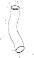
- Fig. 1 shows a perspective view of a fluid tube 100.
- the fluid tube 100 includes in particular a charge air line for conducting charge air or an exhaust gas recirculation line for the return of exhaust gas.
- the fluid hose 100 in the engine compartment of the motor vehicle temperatures of more than 230 ° C and a pressure of can withstand more than 4 bar.
- the fluid hose 100 must withstand high dynamic loads, have a long service life and be inexpensive and reproducible to produce.
- the fluid tube 100 is in this case formed as a dimensionally stable form of hose, which in particular has a two-dimensional or three-dimensional curved course, whereby the molding tube can be particularly advantageously installed in a confined space situation of an engine compartment of a motor vehicle.
- a tube blank is bent into the desired shape of the molding tube.
- the tube blank e.g. by vulcanization, fixed in the desired shape, so that a dimensionally stable molded tube is obtained.
- the dimensionally stable molding tube has a certain flexibility, but the molding tube returns to a bending or twisting of the molding tube back to its original shape.
- the fluid tube 100 has a tube wall 101 with an inner side 103, wherein the inner side 103 faces an inner space 105 of the fluid tube 100.
- the fluid tube 100 has a first longitudinal end 107 with a fluid inlet opening 109 and has a second longitudinal end 111 with a fluid outlet opening 113. Thus, fluid flow through the fluid inlet opening 109 into the interior 105 and exit from the interior 105 through the fluid outlet opening 113 again.
- the fluid tube 100 may further comprise at least one strength carrier, wherein the strength carrier in particular comprises aromatic or aliphatic polyamide fibers, polyoxadiazole fibers, polyester fibers, aramid fibers or mixtures thereof.
- the fluid tube 100 may in particular comprise at least one intermediate layer, which in each case rests against the at least one strength carrier, the intermediate layer in particular comprising silicone rubber.
- the fluid tube 100 may further include, in particular, an inner barrier layer configured to reduce diffusion of the fluid through the barrier layer, the barrier layer being adjacent to the inner surface 103 of the tubing wall 101, and wherein the barrier layer is particularly fluororubber (FKM), a thermoplastic elastomer (US Pat. TPE) and / or a thermoplastic elastomer vulcanizate (TPE-V).
- FKM fluororubber
- TPE thermoplastic elastomer
- TPE-V thermoplastic elastomer vulcanizate
- the fluid tube 100 may further comprise in particular an outer layer, the outer layer in particular comprising chlorinated polyethylene, chlorosulfonated polyethylene, acrylonitrile-butadiene, polyvinyl chloride, chloroprene, epichlorohydrin, epichlorohydrin-ethylene oxide, ethylene-propylene or mixtures thereof.
- fluid hoses 100 in particular charge air lines and / or exhaust gas recirculation lines
- the use of certain engines of motor vehicles can lead to strong pressure fluctuations in the fluid hoses 100 in certain operating situations.
- a negative pressure may temporarily occur in the fluid tube 100, as a result of which the fluid tube 100 may possibly temporarily collapse and a temporary system failure may occur.
- At least one encircling thickening bead 115 is arranged on the tube wall 101 of the fluid tube 100.
- the in Fig. 1 Circumferential thickening bead 115 which is shown only schematically, hereby in particular circumscribes the inside 103 at least in sections.
- a circumferential thickening bead 115 can also be arranged on an outer side 117 of the hose wall 101.
- the hose wall 101 of the fluid hose 100 is stabilized by the at least one encircling thickening bead 115, in particular an optimization of the geometry of the inner side 103 is made possible without additional components, such as e.g. a stabilizing spring in which fluid hose 100 must be received.
- the circumferential thickening bead 115 By the circumferential thickening bead 115, the area moment of inertia of the inside 103 is increased and the tensile rigidity of the fluid tube 100 is increased, whereby the negative pressure resistance of the fluid tube 100 is increased.
- the tube wall 101 is formed integrally with the circumferential thickening bead 115, which ensures that the circumferential thickening bead 115 does not come off the tube wall 101.
- the remaining blank construction remains unchanged and can thus be used for further applications. Except for the arrangement of the circumferential thickening bead 115 on the fluid tube 100, a method for producing the fluid tube 100, or the molding tube, also remains unchanged.
- the at least one encircling thickening bead 115 also allows a high buckling stability of the fluid hose 100, even with small pipe diameters, and the flow behavior of the fluid in the fluid hose 100 can be optimized by a suitable embodiment of the circumferential thickening bead 115.
- an increase in the negative pressure resistance is achieved in charge air lines and / or in exhaust gas recirculation lines.
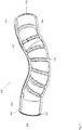
- Fig. 2 shows a perspective view of a fluid tube 100 with a circumferential thickening bead 115 on an inner side 103 according to a first embodiment, wherein the fluid tube 100 is in particular designed as a charge air line and / or as an exhaust gas recirculation line.
- a hose wall 101 of the fluid tube 100 is shown transparent and is an inner space 105 of the fluid tube 100 facing inside 103 of the hose wall 101, however, shown as a surface.
- the fluid tube 100 has a first longitudinal end 107 with a fluid inlet opening 109 and has a second longitudinal end 111 with a fluid outlet opening 113.
- a circumferential thickening bead 115 is arranged, which in this case surrounds the inner side 103 at least in sections. In the in Fig. 2 selected view, only an inner surface of the circumferential thickening bead 115 is visible. In the in Fig. 2 In the illustrated embodiment, the fluid tube 100 has a single circumferential thickening bead 115, which runs around the inside 103 in a helix-shaped manner.
- the tube wall 101 is formed integrally with the circumferential thickening bead 115, which ensures that the circumferential thickening bead 115 does not come off the tube wall 101.
- the helix-shaped thickening bead 115 extends over an extended area of the hose wall 101 and can thereby ensure a particularly uniform stabilization of the hose wall 101 over a large area.
- the helix of the helically formed circumferential thickening bead 115 may have a constant pitch, or the thickening bead 115 may have different pitches at least in sections, in order to provide different extensional stabilizations of the fluid hose 100 at least in certain areas.
- FIGS. 3A, 3B and 3C 11 show schematic views of fluid hoses 100 with circumferential thickening beads 115 according to further embodiments.
- the in the Figs. 3A, 3B, and 3C Fluid hoses 100 shown schematically each have a hose wall 101 with an inner side 103 and an outer side 117.
- the respective fluid hoses 100 each have a first longitudinal end 107 with a fluid inlet opening 109 and each have a second longitudinal end 111 with a fluid outlet opening 113.
- the hose wall 101 has a circumferential thickening bead 115, which is formed on the inner side 103 of the hose wall 101, and projects into the inner space 105 of the fluid hose 100.
- the hose wall 101 has a circumferential thickening bead 115, which is formed on an outer side 117 of the hose wall 101, and directed to the outside.
- the hose wall 101 on circumferential thickening beads 115 which is formed on an outer side 117 of the hose wall 101, and are directed to the outside, and the hose wall 101 in addition circumferential thickening beads 115 which on an inner side 103 of the hose wall 101st are shaped and protrude into an inner space 105 of the fluid tube 100.
- FIGS. 4A, 4B 11 show schematic views of fluid hoses 100 with circumferential thickening beads 115 according to further embodiments.
- the in the Figs. 4A and 4B arranged the Schlauchwandung 101 encircling thickening beads 115 are disposed on an inner side 103 of the hose wall 101 and project into an inner space 105 of the fluid tube 100.
- a longitudinal axis 119 of the fluid tube 100 extends from a first longitudinal end 107 of the fluid tube 100 to an opposite second longitudinal end 111 of Fluid tube 100.
- the thickening bulges 115 encircling the hose wall 101 are arranged in a plane 121, wherein the plane 121 is arranged orthogonal to the longitudinal axis 119.
- the thickening bulges 115 encircling the hose wall 101 are arranged in a plane 121, wherein the plane 121 is arranged at an angle to the longitudinal axis 119.
- FIGS. 5A, 5B show various views of cross sections of circumferential thickening beads 115 in fluid tubes 100.
- the in the Figs. 5A and 5B arranged the Schlauchwandung 101 circumferential thickening beads 115 are disposed on an inner side 103 of the hose wall 101 and project into an inner space 105 of the Fluid hose 100.
- the fluid tube 100 has at a first longitudinal end 107 a fluid inlet opening 109 and has at a second longitudinal end 111 a fluid outlet opening 113.
- fluid can effectively effectively flow from the fluid inlet 109 through the interior 105 of the fluid tube 100 to the fluid outlet 113.
- the circumferential thickening bead 115 has a polygonal, in particular square, cross-section, or an angular, in particular triangular, cross-section.
- the cross section of the circumferential thickening bead 115 may further comprise any square cross section, such as a pentagonal or hexagonal cross section.
- the circumferential thickening bead 115 has a rounded cross-section.
- the circumferential thickening bead 115 in this case has a first side 123, which faces the fluid inlet opening 109, and has a second side 125, which faces the fluid outlet opening 113.
- the first side 123 is inclined with respect to the inside 103 of the fluid tube 100 at a first angle of inclination 127.
- the second side 125 is inclined relative to the inside 103 of the fluid tube 100 at a second angle of inclination 129.
- the first angle of inclination 127 is greater than the second angle of inclination 129.
Landscapes
- Engineering & Computer Science (AREA)
- General Engineering & Computer Science (AREA)
- Mechanical Engineering (AREA)
- Chemical & Material Sciences (AREA)
- Combustion & Propulsion (AREA)
- Rigid Pipes And Flexible Pipes (AREA)
Applications Claiming Priority (1)
| Application Number | Priority Date | Filing Date | Title |
|---|---|---|---|
| DE102017106876.7A DE102017106876A1 (de) | 2017-03-30 | 2017-03-30 | Fluidschlauch mit einem umlaufenden Verdickungswulst |
Publications (3)
| Publication Number | Publication Date |
|---|---|
| EP3382251A2 true EP3382251A2 (fr) | 2018-10-03 |
| EP3382251A3 EP3382251A3 (fr) | 2018-10-17 |
| EP3382251B1 EP3382251B1 (fr) | 2020-07-01 |
Family
ID=61768059
Family Applications (1)
| Application Number | Title | Priority Date | Filing Date |
|---|---|---|---|
| EP18162695.3A Active EP3382251B1 (fr) | 2017-03-30 | 2018-03-20 | Tuyau fluidique pourvu d'un bourrelet d'épaississement entourant |
Country Status (2)
| Country | Link |
|---|---|
| EP (1) | EP3382251B1 (fr) |
| DE (1) | DE102017106876A1 (fr) |
Cited By (1)
| Publication number | Priority date | Publication date | Assignee | Title |
|---|---|---|---|---|
| EP3473429A1 (fr) * | 2017-10-20 | 2019-04-24 | Veritas Ag | Conduite de fluide destinée à conduire un fluide |
Family Cites Families (3)
| Publication number | Priority date | Publication date | Assignee | Title |
|---|---|---|---|---|
| DE1808271A1 (de) * | 1968-09-10 | 1970-04-02 | Yukio Nishikawa | Kunstharzfolien oder Schlaeuche |
| DE3906027A1 (de) * | 1989-02-27 | 1990-08-30 | Fresenius Ag | Schlauch zur fuehrung von medizinischen fluessigkeiten |
| FR2878603B1 (fr) * | 2004-12-01 | 2007-02-23 | Avon Polymeres France Sas Soc | Conduit d'admission d'air |
-
2017
- 2017-03-30 DE DE102017106876.7A patent/DE102017106876A1/de not_active Withdrawn
-
2018
- 2018-03-20 EP EP18162695.3A patent/EP3382251B1/fr active Active
Non-Patent Citations (1)
| Title |
|---|
| None |
Cited By (1)
| Publication number | Priority date | Publication date | Assignee | Title |
|---|---|---|---|---|
| EP3473429A1 (fr) * | 2017-10-20 | 2019-04-24 | Veritas Ag | Conduite de fluide destinée à conduire un fluide |
Also Published As
| Publication number | Publication date |
|---|---|
| EP3382251B1 (fr) | 2020-07-01 |
| EP3382251A3 (fr) | 2018-10-17 |
| DE102017106876A1 (de) | 2018-10-04 |
Similar Documents
| Publication | Publication Date | Title |
|---|---|---|
| EP2357330B1 (fr) | Circuit refrigerant avec amortisseur de bruit pour un corps tubulaire formant un espace creux | |
| EP1878961B1 (fr) | Tuyau flexible | |
| DE19707518C1 (de) | Wellrohr | |
| DE60131057T2 (de) | Faltenbalg mit wendelartiger Struktur | |
| DE102005046367B4 (de) | Hochdruckbeständiger, schwingungsdämpfender Schlauch und Verfahren zur Herstellung desselben | |
| DE10334775A1 (de) | Schlauch mit metallischem Wellrohr | |
| DE202010001667U1 (de) | Flexibles Rohr | |
| EP3473429B1 (fr) | Conduite de fluide destinée à conduire un fluide | |
| EP3382251B1 (fr) | Tuyau fluidique pourvu d'un bourrelet d'épaississement entourant | |
| DE102015012505A1 (de) | Dichtungsanordnung für eine Anschlussvorrichtung und Anschlussvorrichtung für eine Klimaanlage | |
| DE102014118279A1 (de) | Flexibler Turboladerluftkanal mit Einschnürringen | |
| DE102007050655A1 (de) | Wellenschlauch | |
| EP3922893B1 (fr) | Demi-coquille de tube pourvu de cliquet et de joint d'étanchéité | |
| EP4417856B1 (fr) | Dispositif de découplage et de contrôle des vibrations | |
| WO2014060135A1 (fr) | Conduite de fluide à protubérances radiales et/ou à creux radiaux | |
| EP1398554A1 (fr) | Tuyau flexible et son procédé de fabrication | |
| JP2006283843A (ja) | 高耐圧振動吸収ホース及びその製造方法 | |
| DE202007016256U1 (de) | Flexibles Leitungselement für eine Abgasanlage | |
| WO2017137203A1 (fr) | Système de sortie de gaz d'échappement pour un véhicule automobile, véhicule automobile doté d'un tel système de sortie de gaz d'échappement et procédé de production d'un système de sortie de gaz d'échappement | |
| DE102018131717A1 (de) | Dichtungsanordnung, Dichtmuffe und deren Verwendung | |
| DE102019117640A1 (de) | Rohrbauteil | |
| DE102011012376A1 (de) | Rohr-Schlauch-Anordnung | |
| DE19812611C2 (de) | Entkopplungselement in Rohrleitungen | |
| DE102012216097B4 (de) | Entkoppelelement | |
| DE102008019577A1 (de) | Einteiliges HT-LALU Rohr |
Legal Events
| Date | Code | Title | Description |
|---|---|---|---|
| PUAI | Public reference made under article 153(3) epc to a published international application that has entered the european phase |
Free format text: ORIGINAL CODE: 0009012 |
|
| STAA | Information on the status of an ep patent application or granted ep patent |
Free format text: STATUS: THE APPLICATION HAS BEEN PUBLISHED |
|
| PUAL | Search report despatched |
Free format text: ORIGINAL CODE: 0009013 |
|
| AK | Designated contracting states |
Kind code of ref document: A2 Designated state(s): AL AT BE BG CH CY CZ DE DK EE ES FI FR GB GR HR HU IE IS IT LI LT LU LV MC MK MT NL NO PL PT RO RS SE SI SK SM TR |
|
| AX | Request for extension of the european patent |
Extension state: BA ME |
|
| AK | Designated contracting states |
Kind code of ref document: A3 Designated state(s): AL AT BE BG CH CY CZ DE DK EE ES FI FR GB GR HR HU IE IS IT LI LT LU LV MC MK MT NL NO PL PT RO RS SE SI SK SM TR |
|
| AX | Request for extension of the european patent |
Extension state: BA ME |
|
| RIC1 | Information provided on ipc code assigned before grant |
Ipc: F02M 35/10 20060101ALN20180907BHEP Ipc: F16L 11/12 20060101ALI20180907BHEP Ipc: F16L 11/11 20060101AFI20180907BHEP |
|
| STAA | Information on the status of an ep patent application or granted ep patent |
Free format text: STATUS: REQUEST FOR EXAMINATION WAS MADE |
|
| 17P | Request for examination filed |
Effective date: 20190329 |
|
| RBV | Designated contracting states (corrected) |
Designated state(s): AL AT BE BG CH CY CZ DE DK EE ES FI FR GB GR HR HU IE IS IT LI LT LU LV MC MK MT NL NO PL PT RO RS SE SI SK SM TR |
|
| RIC1 | Information provided on ipc code assigned before grant |
Ipc: F16L 11/11 20060101AFI20191217BHEP Ipc: F01N 13/08 20100101ALI20191217BHEP Ipc: F01N 13/16 20100101ALI20191217BHEP Ipc: F02M 35/10 20060101ALN20191217BHEP Ipc: F16L 11/12 20060101ALI20191217BHEP |
|
| GRAP | Despatch of communication of intention to grant a patent |
Free format text: ORIGINAL CODE: EPIDOSNIGR1 |
|
| STAA | Information on the status of an ep patent application or granted ep patent |
Free format text: STATUS: GRANT OF PATENT IS INTENDED |
|
| RIC1 | Information provided on ipc code assigned before grant |
Ipc: F01N 13/16 20100101ALI20200107BHEP Ipc: F02M 35/10 20060101ALN20200107BHEP Ipc: F16L 11/11 20060101AFI20200107BHEP Ipc: F16L 11/12 20060101ALI20200107BHEP Ipc: F01N 13/08 20100101ALI20200107BHEP |
|
| INTG | Intention to grant announced |
Effective date: 20200128 |
|
| GRAS | Grant fee paid |
Free format text: ORIGINAL CODE: EPIDOSNIGR3 |
|
| GRAA | (expected) grant |
Free format text: ORIGINAL CODE: 0009210 |
|
| STAA | Information on the status of an ep patent application or granted ep patent |
Free format text: STATUS: THE PATENT HAS BEEN GRANTED |
|
| AK | Designated contracting states |
Kind code of ref document: B1 Designated state(s): AL AT BE BG CH CY CZ DE DK EE ES FI FR GB GR HR HU IE IS IT LI LT LU LV MC MK MT NL NO PL PT RO RS SE SI SK SM TR |
|
| REG | Reference to a national code |
Ref country code: CH Ref legal event code: EP Ref country code: AT Ref legal event code: REF Ref document number: 1286505 Country of ref document: AT Kind code of ref document: T Effective date: 20200715 |
|
| REG | Reference to a national code |
Ref country code: IE Ref legal event code: FG4D Free format text: LANGUAGE OF EP DOCUMENT: GERMAN |
|
| REG | Reference to a national code |
Ref country code: DE Ref legal event code: R096 Ref document number: 502018001768 Country of ref document: DE |
|
| REG | Reference to a national code |
Ref country code: LT Ref legal event code: MG4D |
|
| PG25 | Lapsed in a contracting state [announced via postgrant information from national office to epo] |
Ref country code: BG Free format text: LAPSE BECAUSE OF FAILURE TO SUBMIT A TRANSLATION OF THE DESCRIPTION OR TO PAY THE FEE WITHIN THE PRESCRIBED TIME-LIMIT Effective date: 20201001 |
|
| REG | Reference to a national code |
Ref country code: NL Ref legal event code: MP Effective date: 20200701 |
|
| PG25 | Lapsed in a contracting state [announced via postgrant information from national office to epo] |
Ref country code: LT Free format text: LAPSE BECAUSE OF FAILURE TO SUBMIT A TRANSLATION OF THE DESCRIPTION OR TO PAY THE FEE WITHIN THE PRESCRIBED TIME-LIMIT Effective date: 20200701 Ref country code: CZ Free format text: LAPSE BECAUSE OF FAILURE TO SUBMIT A TRANSLATION OF THE DESCRIPTION OR TO PAY THE FEE WITHIN THE PRESCRIBED TIME-LIMIT Effective date: 20200701 Ref country code: PT Free format text: LAPSE BECAUSE OF FAILURE TO SUBMIT A TRANSLATION OF THE DESCRIPTION OR TO PAY THE FEE WITHIN THE PRESCRIBED TIME-LIMIT Effective date: 20201102 Ref country code: ES Free format text: LAPSE BECAUSE OF FAILURE TO SUBMIT A TRANSLATION OF THE DESCRIPTION OR TO PAY THE FEE WITHIN THE PRESCRIBED TIME-LIMIT Effective date: 20200701 Ref country code: GR Free format text: LAPSE BECAUSE OF FAILURE TO SUBMIT A TRANSLATION OF THE DESCRIPTION OR TO PAY THE FEE WITHIN THE PRESCRIBED TIME-LIMIT Effective date: 20201002 Ref country code: NO Free format text: LAPSE BECAUSE OF FAILURE TO SUBMIT A TRANSLATION OF THE DESCRIPTION OR TO PAY THE FEE WITHIN THE PRESCRIBED TIME-LIMIT Effective date: 20201001 Ref country code: SE Free format text: LAPSE BECAUSE OF FAILURE TO SUBMIT A TRANSLATION OF THE DESCRIPTION OR TO PAY THE FEE WITHIN THE PRESCRIBED TIME-LIMIT Effective date: 20200701 Ref country code: HR Free format text: LAPSE BECAUSE OF FAILURE TO SUBMIT A TRANSLATION OF THE DESCRIPTION OR TO PAY THE FEE WITHIN THE PRESCRIBED TIME-LIMIT Effective date: 20200701 Ref country code: FI Free format text: LAPSE BECAUSE OF FAILURE TO SUBMIT A TRANSLATION OF THE DESCRIPTION OR TO PAY THE FEE WITHIN THE PRESCRIBED TIME-LIMIT Effective date: 20200701 |
|
| PG25 | Lapsed in a contracting state [announced via postgrant information from national office to epo] |
Ref country code: RS Free format text: LAPSE BECAUSE OF FAILURE TO SUBMIT A TRANSLATION OF THE DESCRIPTION OR TO PAY THE FEE WITHIN THE PRESCRIBED TIME-LIMIT Effective date: 20200701 Ref country code: LV Free format text: LAPSE BECAUSE OF FAILURE TO SUBMIT A TRANSLATION OF THE DESCRIPTION OR TO PAY THE FEE WITHIN THE PRESCRIBED TIME-LIMIT Effective date: 20200701 Ref country code: PL Free format text: LAPSE BECAUSE OF FAILURE TO SUBMIT A TRANSLATION OF THE DESCRIPTION OR TO PAY THE FEE WITHIN THE PRESCRIBED TIME-LIMIT Effective date: 20200701 Ref country code: IS Free format text: LAPSE BECAUSE OF FAILURE TO SUBMIT A TRANSLATION OF THE DESCRIPTION OR TO PAY THE FEE WITHIN THE PRESCRIBED TIME-LIMIT Effective date: 20201101 |
|
| PG25 | Lapsed in a contracting state [announced via postgrant information from national office to epo] |
Ref country code: NL Free format text: LAPSE BECAUSE OF FAILURE TO SUBMIT A TRANSLATION OF THE DESCRIPTION OR TO PAY THE FEE WITHIN THE PRESCRIBED TIME-LIMIT Effective date: 20200701 |
|
| REG | Reference to a national code |
Ref country code: DE Ref legal event code: R097 Ref document number: 502018001768 Country of ref document: DE |
|
| PG25 | Lapsed in a contracting state [announced via postgrant information from national office to epo] |
Ref country code: SM Free format text: LAPSE BECAUSE OF FAILURE TO SUBMIT A TRANSLATION OF THE DESCRIPTION OR TO PAY THE FEE WITHIN THE PRESCRIBED TIME-LIMIT Effective date: 20200701 Ref country code: DK Free format text: LAPSE BECAUSE OF FAILURE TO SUBMIT A TRANSLATION OF THE DESCRIPTION OR TO PAY THE FEE WITHIN THE PRESCRIBED TIME-LIMIT Effective date: 20200701 Ref country code: RO Free format text: LAPSE BECAUSE OF FAILURE TO SUBMIT A TRANSLATION OF THE DESCRIPTION OR TO PAY THE FEE WITHIN THE PRESCRIBED TIME-LIMIT Effective date: 20200701 Ref country code: EE Free format text: LAPSE BECAUSE OF FAILURE TO SUBMIT A TRANSLATION OF THE DESCRIPTION OR TO PAY THE FEE WITHIN THE PRESCRIBED TIME-LIMIT Effective date: 20200701 |
|
| PLBE | No opposition filed within time limit |
Free format text: ORIGINAL CODE: 0009261 |
|
| STAA | Information on the status of an ep patent application or granted ep patent |
Free format text: STATUS: NO OPPOSITION FILED WITHIN TIME LIMIT |
|
| PG25 | Lapsed in a contracting state [announced via postgrant information from national office to epo] |
Ref country code: AL Free format text: LAPSE BECAUSE OF FAILURE TO SUBMIT A TRANSLATION OF THE DESCRIPTION OR TO PAY THE FEE WITHIN THE PRESCRIBED TIME-LIMIT Effective date: 20200701 |
|
| 26N | No opposition filed |
Effective date: 20210406 |
|
| PG25 | Lapsed in a contracting state [announced via postgrant information from national office to epo] |
Ref country code: SK Free format text: LAPSE BECAUSE OF FAILURE TO SUBMIT A TRANSLATION OF THE DESCRIPTION OR TO PAY THE FEE WITHIN THE PRESCRIBED TIME-LIMIT Effective date: 20200701 |
|
| PG25 | Lapsed in a contracting state [announced via postgrant information from national office to epo] |
Ref country code: SI Free format text: LAPSE BECAUSE OF FAILURE TO SUBMIT A TRANSLATION OF THE DESCRIPTION OR TO PAY THE FEE WITHIN THE PRESCRIBED TIME-LIMIT Effective date: 20200701 |
|
| PG25 | Lapsed in a contracting state [announced via postgrant information from national office to epo] |
Ref country code: MC Free format text: LAPSE BECAUSE OF FAILURE TO SUBMIT A TRANSLATION OF THE DESCRIPTION OR TO PAY THE FEE WITHIN THE PRESCRIBED TIME-LIMIT Effective date: 20200701 |
|
| REG | Reference to a national code |
Ref country code: CH Ref legal event code: PL |
|
| REG | Reference to a national code |
Ref country code: BE Ref legal event code: MM Effective date: 20210331 |
|
| PG25 | Lapsed in a contracting state [announced via postgrant information from national office to epo] |
Ref country code: CH Free format text: LAPSE BECAUSE OF NON-PAYMENT OF DUE FEES Effective date: 20210331 Ref country code: IE Free format text: LAPSE BECAUSE OF NON-PAYMENT OF DUE FEES Effective date: 20210320 Ref country code: LI Free format text: LAPSE BECAUSE OF NON-PAYMENT OF DUE FEES Effective date: 20210331 Ref country code: LU Free format text: LAPSE BECAUSE OF NON-PAYMENT OF DUE FEES Effective date: 20210320 |
|
| REG | Reference to a national code |
Ref country code: DE Ref legal event code: R082 Ref document number: 502018001768 Country of ref document: DE |
|
| PG25 | Lapsed in a contracting state [announced via postgrant information from national office to epo] |
Ref country code: BE Free format text: LAPSE BECAUSE OF NON-PAYMENT OF DUE FEES Effective date: 20210331 |
|
| GBPC | Gb: european patent ceased through non-payment of renewal fee |
Effective date: 20220320 |
|
| PG25 | Lapsed in a contracting state [announced via postgrant information from national office to epo] |
Ref country code: GB Free format text: LAPSE BECAUSE OF NON-PAYMENT OF DUE FEES Effective date: 20220320 |
|
| P01 | Opt-out of the competence of the unified patent court (upc) registered |
Effective date: 20230515 |
|
| PG25 | Lapsed in a contracting state [announced via postgrant information from national office to epo] |
Ref country code: CY Free format text: LAPSE BECAUSE OF FAILURE TO SUBMIT A TRANSLATION OF THE DESCRIPTION OR TO PAY THE FEE WITHIN THE PRESCRIBED TIME-LIMIT Effective date: 20200701 |
|
| PG25 | Lapsed in a contracting state [announced via postgrant information from national office to epo] |
Ref country code: HU Free format text: LAPSE BECAUSE OF FAILURE TO SUBMIT A TRANSLATION OF THE DESCRIPTION OR TO PAY THE FEE WITHIN THE PRESCRIBED TIME-LIMIT; INVALID AB INITIO Effective date: 20180320 |
|
| PG25 | Lapsed in a contracting state [announced via postgrant information from national office to epo] |
Ref country code: MK Free format text: LAPSE BECAUSE OF FAILURE TO SUBMIT A TRANSLATION OF THE DESCRIPTION OR TO PAY THE FEE WITHIN THE PRESCRIBED TIME-LIMIT Effective date: 20200701 |
|
| REG | Reference to a national code |
Ref country code: AT Ref legal event code: MM01 Ref document number: 1286505 Country of ref document: AT Kind code of ref document: T Effective date: 20230320 |
|
| PG25 | Lapsed in a contracting state [announced via postgrant information from national office to epo] |
Ref country code: AT Free format text: LAPSE BECAUSE OF NON-PAYMENT OF DUE FEES Effective date: 20230320 |
|
| PG25 | Lapsed in a contracting state [announced via postgrant information from national office to epo] |
Ref country code: AT Free format text: LAPSE BECAUSE OF NON-PAYMENT OF DUE FEES Effective date: 20230320 |
|
| PG25 | Lapsed in a contracting state [announced via postgrant information from national office to epo] |
Ref country code: MT Free format text: LAPSE BECAUSE OF FAILURE TO SUBMIT A TRANSLATION OF THE DESCRIPTION OR TO PAY THE FEE WITHIN THE PRESCRIBED TIME-LIMIT Effective date: 20200701 |
|
| PGFP | Annual fee paid to national office [announced via postgrant information from national office to epo] |
Ref country code: DE Payment date: 20250319 Year of fee payment: 8 |
|
| PGFP | Annual fee paid to national office [announced via postgrant information from national office to epo] |
Ref country code: FR Payment date: 20250324 Year of fee payment: 8 |
|
| PGFP | Annual fee paid to national office [announced via postgrant information from national office to epo] |
Ref country code: IT Payment date: 20250331 Year of fee payment: 8 |
|
| PG25 | Lapsed in a contracting state [announced via postgrant information from national office to epo] |
Ref country code: TR Free format text: LAPSE BECAUSE OF FAILURE TO SUBMIT A TRANSLATION OF THE DESCRIPTION OR TO PAY THE FEE WITHIN THE PRESCRIBED TIME-LIMIT Effective date: 20200701 |
|
| PGFP | Annual fee paid to national office [announced via postgrant information from national office to epo] |
Ref country code: AT Payment date: 20260410 Year of fee payment: 5 |